
SDS 5359-21 - Hammer MILWAUKEE - Free user manual and instructions
Find the device manual for free SDS 5359-21 MILWAUKEE in PDF.

| Brand | Milwaukee |
| Model | SDS 5359-21 |
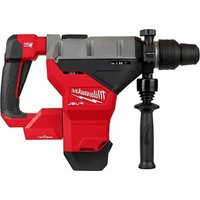
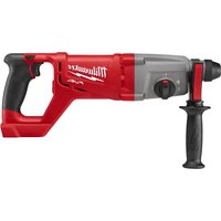
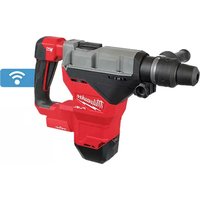
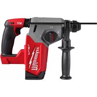
| Product Type | Rotary Hammer Drill |
| Power Supply | 120 V AC, 10 A, 60 Hz |
| Power | 1200 W (estimated) |
| No-load Speed | 0 - 1500 rpm |
| No-load Impact Rate | 0 - 5500 blows/min |
| Operating Modes | Drilling, rotary hammer, hammer only |
| Chuck Type | SDS-plus |
| Drilling Capacity (Concrete) | Up to 25 mm (1") (estimated) |
| Side Handle | Yes, adjustable |
| Depth Gauge | Yes, adjustable |
| Anti-vibration System | Yes |
| Variable Speed | Yes, by trigger |
| Forward/Reverse | Yes, switch |
| Torque Limiter | Yes, built-in non-adjustable |
| Weight | Approximately 6.8 kg (15 lb) |
| Length | Approximately 40 cm |
| Width | Approximately 8 cm |
| Height | Approximately 25 cm |
| Housing Material | Reinforced plastic |
| Maintenance | Clean with damp cloth and mild soap; do not immerse |
| Warranty | 5 years |
| Safety Standards | ANSI Z87.1, OSHA, Double insulation (on some models) |
Frequently Asked Questions - SDS 5359-21 MILWAUKEE
User questions about SDS 5359-21 MILWAUKEE
0 question about this device. Answer the ones you know or ask your own.
Ask a new question about this device
Download the instructions for your Hammer in PDF format for free! Find your manual SDS 5359-21 - MILWAUKEE and take your electronic device back in hand. On this page are published all the documents necessary for the use of your device. SDS 5359-21 by MILWAUKEE.
USER MANUAL SDS 5359-21 MILWAUKEE
WARNING To reduce the risk of injury, user must read and understand operator's manual.
⚠ WARNING Read all safety warnings, instructions, illustrations and specifica-
tions provided with this power tool. Failure to follow all instructions listed below may result in electric shock, fire and/or serious injury. Save all warnings and instructions for future reference. The term "power tool" in the warnings refers to your mains-operated (corded) power tool or battery-operated (cordless) power tool.
WORK AREA SAFETY
- Keep work area clean and well lit. Cluttered or dark areas invite accidents.
- Do not operate power tools in explosive atmospheres, such as in the presence of flammable liquids, gases or dust. Power tools create sparks which may ignite the dust or fumes.
- Keep children and bystanders away while operating a power tool. Distractions can cause you to lose control.
ELECTRICAL SAFETY
- Power tool plugs must match the outlet. Never modify the plug in any way. Do not use any adapter plugs with earthed (grounded) power tools. Unmodified plugs and matching outlets will reduce risk of electric shock.
- Avoid body contact with earthed or grounded surfaces, such as pipes, radiators, ranges and refrigerators. There is an increased risk of electric shock if your body is earthed or grounded.
- Do not expose power tools to rain or wet conditions. Water entering a power tool will increase the risk of electric shock.
- Do not abuse the cord. Never use the cord for carrying, pulling or unplugging the power tool. Keep cord away from heat, oil, sharp edges or moving parts. Damaged or entangled cords increase the risk of electric shock.
- When operating a power tool outdoors, use an extension cord suitable for outdoor use. Use of a cord suitable for outdoor use reduces the risk of electric shock.
- If operating a power tool in a damp location is unavoidable, use a ground fault circuit interrupter (GFCI) protected supply. Use of an GFCI reduces the risk of electric shock.
PERSONAL SAFETY
- Stay alert, watch what you are doing and use common sense when operating a power tool. Do not use a power tool while you are tired or under the influence of drugs, alcohol or medication. A moment of inattention while operating power tools may result in serious personal injury.
- Use personal protective equipment. Always wear eye protection. Protective equipment such as a dust mask, non-skid safety shoes, hard hat or hearing protection used for appropriate conditions will reduce personal injuries.
- Prevent unintentional starting. Ensure the switch is in the off-position before connecting to power source and/or battery pack, picking up or carrying the tool. Carrying power tools with your finger on the switch or energizing power tools that have the switch on invites accidents.
- Remove any adjusting key or wrench before turning the power tool on. A wrench or a key left attached to a rotating part of the power tool may result in personal injury.
- Do not overreach. Keep proper footing and balance at all times. This enables better control of the power tool in unexpected situations.
- Dress properly. Do not wear loose clothing or jewelry. Keep your hair and clothing away from moving parts. Loose clothes, jewelry or long hair can be caught in moving parts.
- If devices are provided for the connection of dust extraction and collection facilities, ensure these are connected and properly used. Use of dust collection can reduce dust-related hazards.
- Do not let familiarity gained from frequent use of tools allow you to become complacent and ignore tool safety principles. A careless action can cause severe injury within a fraction of a second.
POWER TOOL USE AND CARE
- Do not force the power tool. Use the correct power tool for your application. The correct power tool will do the job better and safer at the rate for which it was designed.
- Do not use the power tool if the switch does not turn it on and off. Any power tool that cannot be controlled with the switch is dangerous and must be repaired.
- Disconnect the plug from the power source and/or remove the battery pack, if detachable, from the power tool before making any adjustments, changing accessories, or storing power tools. Such preventive safety measures reduce the risk of starting the power tool accidentally.
- Store idle power tools out of the reach of children and do not allow persons unfamiliar with the power tool or these instructions to operate the power tool. Power tools are dangerous in the hands of untrained users.
- Maintain power tools and accessories. Check for misalignment or binding of moving parts, breakage of parts and any other condition that may affect the power tool's operation. If damaged, have the power tool repaired before use. Many accidents are caused by poorly maintained power tools.
- Keep cutting tools sharp and clean. Properly maintained cutting tools with sharp cutting edges are less likely to bind and are easier to control.
- Use the power tool, accessories and tool bits etc. in accordance with these instructions, taking into account the working conditions and the work to be performed. Use of the power tool for operations different from those intended could result in a hazardous situation.
- Keep handles and grasping surfaces dry, clean and free from oil and grease. Slippery handles and grasping surfaces do not allow for safe handling and control of the tool in unexpected situations.
SERVICE
- Have your power tool serviced by a qualified repair person using only identical replacement parts. This will ensure that the safety of the power tool is maintained.
SPECIFIC SAFETY RULES FOR ROTARY HAMMER
- Wear ear protectors. Exposure to noise can cause hearing loss.
- Use auxiliary handle(s), if supplied with the tool. Loss of control can cause personal injury.
- Hold power tool by insulated gripping surfaces, when performing an operation where the cutting accessory may contact hidden wiring or its own cord. Cutting accessory contacting a “live” wire may make exposed metal parts of the power tool “live” and could give the operator an electric shock.
- Keep hands away from all cutting edges and moving parts.
- Cut embedded rebar only if this operation does not affect the integrity of the building. If in doubt, consult a structural engineer. Tool operator fully responsible for adverse structural effects.
WARNING To reduce the risk of injury, when working in dusty situations, wear appropriate respiratory protection or use an OSHA compliant dust extraction solution.
• Always use common sense and be cautious when using tools. It is not possible to anticipate every situation that could result in a dangerous outcome. Do not use this tool if you do not understand these operating instructions or you feel the work is beyond your capability; contact Milwaukee Tool or a trained professional for additional information or training.
- Maintain labels and nameplates. These carry important information. If unreadable or missing, contact a MILWAUKEE service facility for a free replacement.
•WARNING Some dust created by power sanding, sawing, grinding, drilling, and other construction activities contains chemicals known to cause cancer, birth defects or other reproductive harm. Some examples of these chemicals are:
- lead from lead-based paint
• crystalline silica from bricks and cement and other masonry products, and
• arsenic and chromium from chemically-treated lumber. Your risk from these exposures varies, depending on how often you do this type of work. To reduce your exposure to these chemicals: work in a well ventilated area, and work with approved safety equipment, such as those dust masks that are specially designed to filter out microscopic particles.
SPECIFICATIONS
| Cat. No. | 5268-21 |
| Volts | 120 AC |
| Amps | 8 |
| No Load RPM | 0 - 1500 |
| BPM | 0 - 5500 |
| Type | SDS Plus |
| Capacities | |
| Twist bit | 1-1/8" |
| Core Bit | 3" |
SYMBOLGY
| Double Insulated | |
| Volts | |
| ~ | Alternating Current |
| A | Amps |
| n0XXXX min-1 | No Load Revolutions per Minute (RPM) |
| BPM | Blows per Minute Under Load (BPM) |
| MAVS | Anti-Vibration System |
| Read Operator's Manual | |
| cULus | UL Listing for Canada and U.S. |
| NOM | Approval Mark for Mexico |
FUNCTIONAL DESCRIPTION
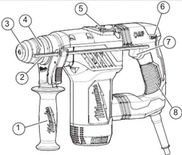
- Side handle
- Depth gauge rod
- Bit holder
-
Bit release collar
-
Mode selector knob
- Control switch
- Trigger
- Handle
EXTENSION CORDS
Grounded tools require a three wire extension cord. Double insulated tools can use either a two or three wire extension cord. As the distance from the supply outlet increases, you must use a heavier gauge extension cord. Using extension cords with inadequately sized wire causes a serious drop in voltage, resulting in loss of power and possible tool damage. Refer to the table shown to determine the required minimum wire size.
The smaller the gauge number of the wire, the greater the capacity of the cord. For example, a 14 gauge cord can carry a higher current than a 16 gauge cord. When using more than one extension cord to make up the total length, be sure each cord contains at least the minimum wire size required. If you are using one extension cord for more than one tool, add the nameplate amperes and use the sum to determine the required minimum wire size.
Guidelines for Using Extension Cords
- If you are using an extension cord outdoors, be sure it is marked with the suffix "W-A" ("W" in Canada) to indicate that it is acceptable for outdoor use.
- Be sure your extension cord is properly wired and in good electrical condition. Always replace a damaged extension cord or have it repaired by a qualified person before using it.
- Protect your extension cords from sharp objects, excessive heat and damp or wet areas.
| Recommended Minimum Wire Gauge For Extension Cords* | |||||
| Nameplate Amps | Extension Cord Length | ||||
| 25' | 50' | 75' | 100' | 150' | |
| 0 - 2.0 | 18 | 18 | 18 | 18 | 16 |
| 2.1 - 3.4 | 18 | 18 | 18 | 16 | 14 |
| 3.5 - 5.0 | 18 | 18 | 16 | 14 | 12 |
| 5.1 - 7.0 | 18 | 16 | 14 | 12 | 12 |
| 7.1 - 12.0 | 16 | 14 | 12 | 10 | -- |
| 12.1 - 16.0 | 14 | 12 | 10 | -- | -- |
| 16.1 - 20.0 | 12 | 10 | -- | -- | -- |
* Based on limiting the line voltage drop to five volts at 150% of the rated amperes.
GROUNDING
AWARNING Improperly connecting the grounding wire can result in the risk of electric shock. Check with a qualified electrician if you are in doubt as to whether the outlet is properly grounded. Do not modify the plug provided with the tool. Never remove the grounding prong from the plug. Do not use the tool if the cord or plug is damaged. If damaged, have it repaired by a MILWAUKEE service facility before use. If the plug will not fit the outlet, have proper outlet installed by a qualified electrician.
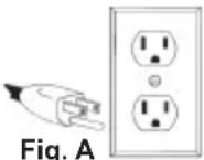
Grounded Tools (Three-Prong Plugs)
Tools marked “Grounding Required” have a three wire cord and three prong grounding plug. The plug must be connected to a properly grounded outlet (See Figure A). If the tool should electrically malfunction or break down, grounding provides a low resistance path to carry electricity away from the user, reducing the risk of electric shock.
The grounding prong in the plug is connected through the green wire inside the cord to the grounding system in the tool. The green wire in the cord must be the only wire connected to the tool's grounding system and must never be attached to an electrically "live" terminal.
Your tool must be plugged into an appropriate outlet, properly installed and grounded in accordance with all codes and ordinances. The plug and outlet should look like those in Figure A.
Double Insulated Tools (Two-Prong Plugs)
Tools marked "Double Insulated" do not require grounding. They have a special double insulation system which satisfies OSHA requirements and complies with the applicable standards of Underwriters Laboratories, Inc., the Canadian Standard Association and the National Electrical Code. Double Insulated tools may be used in either of the 120 volt outlets shown in Figures B and C.
ASSEMBLY
WARNING To reduce the risk of injury, always unplug tool before changing or removing accessories. Only use accessories specifically recommended for this tool. Others may be hazardous.
Always use a side handle when using this tool. Always brace or hold securely.
Adjusting the Side Handle Position
- Loosen the side handle by unscrewing the side handle grip until the side handle rotates freely.
- Rotate the side handle to the desired position.
- Tighten the side handle grip securely.
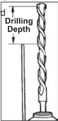
Setting the Depth Gauge
- Press in the clamping lever.
- Slide the depth gauge rod backward or forward until it is set for the desired depth.
NOTE: The drilling depth is the distance between the tip of the bit and the tip of the depth gauge rod. - Release the clamping lever.
WARNING To reduce the risk of injury, do not grasp the bit while the chuck is rotating or while the bit is falling from the chuck.
Installing Bits and Chisels
NOTE: Only use accessories with SDS or SDS Plus shanks.
Be sure that the shank of the bit is clean. Dirt particles may cause the bit to line up improperly. Do not use bits larger than the maximum recommended capacity of the drill because gear damage or motor overloading may result. For best performance, be sure that the bit is properly sharpened and the shank is lightly greased before use. Use caution when handling hot bits and chisels.
- Unplug tool.
- Insert the bit or chisel into the nose of the tool.
- Push bit into tool until it locks.
- Check to see that the bit is locked by tugging on it.
- To remove bits and chisels, pull back on the bit release collar and remove bit.
OPERATION
AWARNING To reduce the risk of injury, always unplug tool before attaching or
removing accessories or making adjustments. Use only specifically recommended accessories. Others may be hazardous.
Always wear proper eye protection marked to comply with ANSI Z87.1.
When working in dusty situations, wear appropriate respiratory protection or use an OSHA compliant dust extraction solution.
Keep hands and cord away from the bit and all moving parts.
Always use a side handle when using this tool. Always brace or hold securely.
Cut embedded rebar only if this operation does not affect the integrity of the building. If in doubt, consult a structural engineer. Tool operator fully responsible for adverse structural effects.
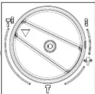
Selecting Action
MILWAUKEE Rotary Hammers have three settings: rotation only, rotary hammer, and hammer only. Always allow the motor to come to a complete stop before changing the mode selection to avoid dam-
age to the tool.
-
For rotation only, turn the selector lever so the arrow on the lever points to the twist drill symbol.
-
For rotary hammering, turn the selector lever so the arrow points to the hammer and twist drill symbol.
-
For hammering only, turn the selector lever so the ar mer symbol.
natural_image
Pure mechanical diagram of a circular component with internal lines and arrows, no text or symbols present- To freely rotate the bit to the desired angle hammering only, turn the selector lever to the symbol. Then, follow step 3.
NOTE: To engage the hammering mechanism, maintain pressure on the bit. When pressure on the bit is released, the hammering action will stop.
Starting and Stopping
- To start the tool, grasp the handle(s) firmly and pull the trigger.
- To stop the tool, release the trigger. Make sure the tool comes to a complete stop before laying the tool down.
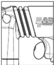
⚠ WARNING Applying greater pressure does not increase the tool's effectiveness.
If the applied working pressure is too high, the shock absorber will be pushed together making the vibrations to the handle noticeably stronger.
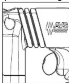
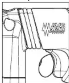
Operator Force
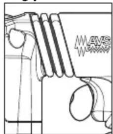
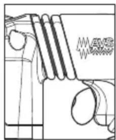
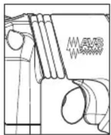
The Anti-Vibration System provides the operator with comfort without sacrificing power or performance. Ideal operator force compresses the bellows slightly and allows the tool to work aggressively while the handle remains steady.
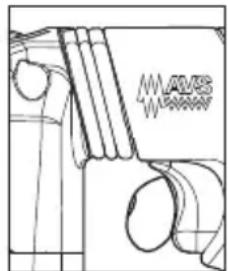
Excessive force compresses the bellows significantly and reduces vibration dampening. Users will be able to feel the difference and should adjust the force to the handle accordingly.
natural_image
Pure technical line drawing of a mechanical component without any text, numbers, or symbolsToo Little force
natural_image
Pure mechanical diagram showing a lever and gear assembly without any text or symbolsCorrect Too much force force
natural_image
Technical line drawing of a mechanical component with no visible text or symbolsUsing the Control Switch
Always allow the motor to come to a complete stop before using the control switch to avoid damage to the tool.
For forward (clockwise) rotation, push in the control switch from the right side of the tool. Check the direction of rotation before use.
For reverse (counterclockwise) rotation, push in the control switch from the left side of the tool. Check direction of rotation before use.
Operating
Position the tool, grasp the handles firmly and pull the trigger. Always hold the tool securely using both handles to maintain control. This tool has been designed to achieve top performance with only moderate pressure. Let the tool do the work.
If the speed begins to drop off when drilling large or deep holes, pull the bit partially out of the hole while the tool is running to help clear dust. Do not use water to settle the dust since it will clog the bit flutes and tend to make the bit bind in the hole. If the bit should bind, a built-in, non-adjustable slip clutch prevents the bit from turning. If this occurs, stop the tool, free the bit and begin again.
Cold Starting
If this tool is stored for a long period of time or at cold temperatures, it may not hammer initially because the lubrication has become stiff. To warm up the tool:
- Insert and lock a bit or chisel into the tool.
fo2. Pull the trigger and apply force to the bit or chisel against a concrete or wood surface for a few seconds. Release the trigger
- Repeat until the tool starts hammering. The colder the tool is, the longer it will take to warm up.
Using Rotary Percussion Core Bits
Core Bits are useful for drilling large or long holes in concrete. MILWAUKEE Heavy-Duty Core Bits have heat-treated steel bodies with durable carbide tips. These core bits are specially designed for fast, accurate drilling with combined hammering and rotary action.
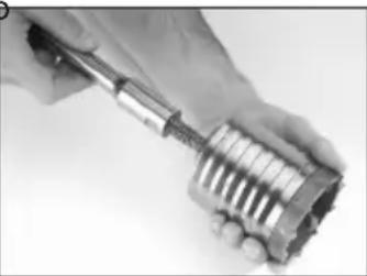
- Clean and lubricate the threads on the adapter and core bit to make later removal easier. Thread the adapter shank to the rear of the core bit.
- Push the guide plate onto the pointed end of the center pin. Insert the center pin and guide plate assembly into the core bit. Be sure the small end of the center pin is securely placed into the hole in the center of the core bit.
For LHS systems, screw the threaded end of the centering bit into the core bit.
NOTE: If using an extension, first thread the adapter shank to the extension. Then thread the core bit to the extension.
- Insert the adapter into the nose of the tool as described in "Installing Bits and Chisels". Set the knob to the "hammering with rotation" setting.
- Press the centering bit firmly against your center mark, hold the tool firmly and pull the trigger.
NOTE: If the 48-20-5099 threaded stud is used, or a center pin and guide plate are not available, use a template or notched board to start the hole.
- Start the tool. After drilling to about the depth of the core bit teeth, remove the center pin and guide plate from the core system). Resume drilling
- To change the core bit, hold the tool upwards, pointing it away from your body, and run it briefly in forward to loosen the core bit from the adapter.
NOTE: To make deeper holes, remove the core bit, break and remove the core, then resume drilling. When drilling long or deep holes, after each inch of penetration pull the bit partially out of the hole while the tool is running, to help clear dust from the bit flutes. Dust can clog the bit flutes and can make the bit bind in the hole. If this occurs, stop the tool, free the bit and begin again.
natural_image
Close-up of a hand holding a mechanical tool with threaded shafts (no visible text or symbols)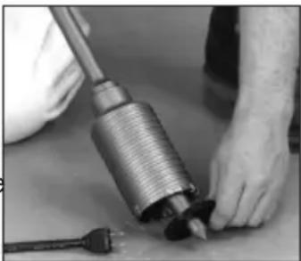
natural_image
Close-up of hands using a mechanical tool to adjust or install a component (no visible text or symbols)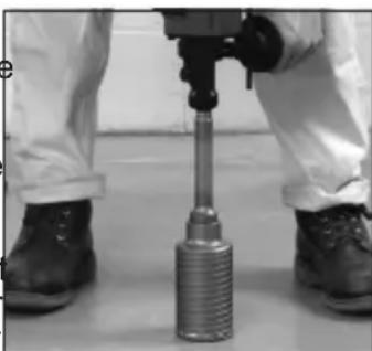
natural_image
Close-up of a person operating a mechanical tool with a cylindrical component (no visible text or symbols)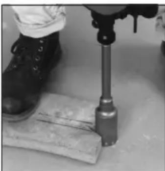
natural_image
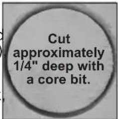
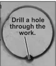
Close-up of a person using a mechanical tool on a wooden surface, no visible text or symbolsDrilling Large Diameter Holes with Core Bits When drilling holes with large diameter core bits, dust may build up in the cut and can cause the tool to stall, bind, or cut slowly. By creating an opening for the dust to escape, drilling time, bit stress, and tool stress can be reduced.
- Start the cut as normal.
- Once the bit is firmly established in the cut (about 1/4" deep) remove the bit from the cut.
- Remove the bit from the tool.
- Install a standard fluted bit approximately 7/8" in diameter, onto the tool.
-
Drill a perpendicular hole through the kerf of the large hole.
-
Depending on the location of the work, the hole should either break through the other side of the hole/floor or extend 4"-5" past the end of the workpiece (such as into the dirt below a concrete slab).
- If dust builds up in the hole, vacuum it out and continue drilling.
-
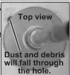
If drilling through a wall, the hole for dust should be drilled on the lowest part of the large hole kerf as the dust will fall there when drilling and can be evacuated more easily.
-
Reinstall the core bit and continue drilling. Dust and debris will fall through the hole and optimize the cutting ability of the bit.
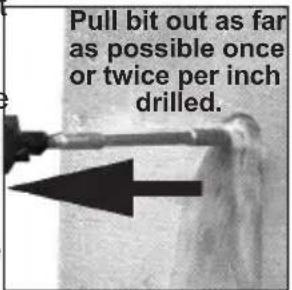
NOTE: If unable to drill a hole in the kerf, pull back on the bit with the hammer running. This will remove some of the dust and debris from the cut. Repeat this for every inch of drilling. If necessary, vacuum dust and debris from the cut and surrounding area.
-
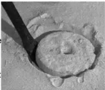
For core bits, once the maximum core bit depth is drilled, the core must be broken and removed.
-
Install a chisel bit.
- Place the chisel into the hole kerf.
- Chisel down into the kerf at several points until the core is loose or broken.
- Remove the core and vacuum/remove any remaining dust and debris.
• Install the core bit and continue the cut.

natural_image
Close-up of a circular, textured object with a dark rod inserted, resting on sandy ground (no visible text or symbols)Chiseling and Chipping
MILWAUKEE Rotary Hammers may be used for chipping and chiseling.
When chiseling, hold the tool at an angle to the workpiece. Work from a corner or close to the edge of the workpiece, breaking off one small area at a time rather than attempting too large an area. A variety of accessories are available.
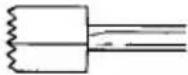 | Bushing ToolsUsed to surface concrete. |
 | Mortar Cutting Chisels (Seam Tools)For removing old mortar for tuck pointing or caulking. |
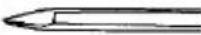 | Bull PointsFor demolition work and starting holes in concrete slabs. |
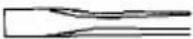 | Flat ChiselsFor edging, chipping or channeling. |
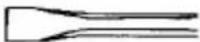 | Scaling ChiselsFor removing weld spatter or scale and cutting straight lines. |
 | Slotting ChiselFor slotting and cutting between drilled holes in concrete and masonry. |
MAINTENANCE
WARNING To reduce the risk of injury, always unplug the tool before performing any maintenance. Never disassemble the tool. Contact a MILWAUKEE service facility for ALL repairs.
Maintaining Tools
Keep your tool in good repair by adopting a regular maintenance program. Inspect your tool for issues such as undue noise, misalignment or binding of moving parts, breakage of parts, or any other condition that may affect the tool operation. Return the tool to a MILWAUKEE service facility for repair. After six months to one year, depending on use, return the tool to a MILWAUKEE service facility for inspection.
⚠ WARNING To reduce the risk of personal injury, electric shock and damage, never immerse your tool in liquid or allow a liquid to flow inside it.
Cleaning
Clean dust and debris from any vents. Keep tool clean, dry and free of oil or grease. Use only mild soap and a damp cloth to clean, since certain cleaning agents and solvents are harmful to plastics and other insulated parts. Some of these include gasoline, turpentine, lacquer thinner, paint thinner, chlorinated cleaning solvents, ammonia and household detergents containing ammonia. Never use flammable or combustible solvents around tools.
Repairs
For repairs, return the tool to the nearest authorized service center.
ACCESSORIES
WARNING Use only recommended accessories. Others may be hazardous.
For a complete listing of accessories, go online to www.milwaukeeetool.com or contact a distributor.
1-800-SAWDUST (1.800.729.3878)
Monday-Friday, 7:00 AM - 6:30 PM CST
or visit www.milwaukeeetool.com
Contact Corporate After Sales Service Technical Support with technical, service/repair, or warranty questions.
Email: metproductsupport@milwaukeeetool.com
Become a Heavy Duty Club Member at www.milwaukeeetool.com to receive important notifications regarding your tool purchases.
SERVICE - CANADA
Milwaukee Tool (Canada) Ltd 1.800.268.4015
Monday-Friday, 7:00 AM - 4:30 PM CST
or visit www.milwaukeetool.ca
LIMITED WARRANTY USA & CANADA
Every MILWAUKEE power tool* (see exceptions below) is warranted to the original purchaser only to be free from defects in material and workmanship. Subject to certain exceptions, MILWAUKEE will repair or replace any part on an electric power tool which, after examination, is determined by MILWAUKEE to be defective in material or workmanship for a period of five (5) years** after the date of purchase unless otherwise noted. Return of the power tool to a MILWAUKEE factory Service Center location or MILWAUKEE Authorized Service Station, freight prepaid and insured, is required. A copy of the proof of purchase should be included with the return product. This warranty does not apply to damage that MILWAUKEE determines to be from repairs made or attempted by anyone other than MILWAUKEE authorized personnel, misuse, alterations, abuse, normal wear and tear, lack of maintenance, or accidents.
Normal Wear: Many power tools need periodic parts replacement and service to achieve best performance. This warranty does not cover repair when normal use has exhausted the life of a part including, but not limited to, chucks, brushes, cords, saw shoes, blade clamps, o-rings, seals, bumpers, driver blades, pistons, strikers, lifters, and bumper cover washers.
*This warranty does not cover Air Nailers & Staplers; Airless Paint Sprayer; Cordless Battery Packs; Gasoline Driven Portable Power Generators; Hand Tools; Hoist – Electric, Lever & Hand Chain; M12™ Heated Gear; Reconditioned Product; and Test & Measurement Products. There are separate and distinct warranties available for these products.
**The warranty period for Job Site Radios, M12™ Power Port, M18™ Power Source, Jobsite Fan and Trade Titan™ Industrial Work Carts is one (1) year from the date of purchase. The warranty period for the M18 FUEL™ 1" D-Handle High Torque Impact Wrenches, Drain Cleaning Cables, AIRSNAKE™ Drain Cleaning Air Gun Accessories, REDLITHIUM™ USB Laser Levels and TRAPSNAKE™ 25' Auger w/ CABLE DRIVE™ is two (2) years from the date of purchase. The warranty period for the M18™ Compact Heat Gun, 8 Gallon Dust Extractor, M18™ Framing Nailers, M18 FUEL™ 1/2" Ext. Anvil Controlled Torque Impact Wrench w/ ONE-KEY™, M18 FUEL™ 1" High Torque Impact Wrench w/ ONE-KEY™, M18 FUEL™ 2 Gal. Compact Quiet Compressor, M12™ Laser Levels, 165' Laser Detector, M12™ 23GA Pin Nailer, M18 FUEL™ 1/4" Blind Rivet Tool w/ ONE-KEY™, M12 FUEL™ Low Speed Tire Buffer, M18 FUEL™ Random Orbital Polishers, and the M18™ Utility Fencing Stapler is three (3) years from the date of purchase. The warranty period for the LED in the LED Work Light and the LED Upgrade Bulb for the Work Light is the lifetime of the product subject to the limitations above. If during normal use the LED or LED Bulb fails, the part will be replaced free of charge.
Warranty Registration is not necessary to obtain the applicable warranty on a MILWAUKEE power tool product. The manufacturing date of the product will be used to determine the warranty period if no proof of purchase is provided at the time warranty service is requested. ACCEPTANCE OF THE EXCLUSIVE REPAIR AND REPLACEMENT REMEDIES DESCRIBED HEREIN IS A CONDITION OF THE CONTRACT FOR THE PURCHASE OF EVERY MILWAUKEE PRODUCT. IF YOU DO NOT AGREE TO THIS CONDITION, YOU SHOULD NOT PURCHASE THE PRODUCT. IN NO EVENT SHALL MILWAUKEE BE LIABLE FOR ANY INCIDENTAL, SPECIAL, CONSEQUENTIAL OR PUNITIVE DAMAGES, OR FOR ANY COSTS, ATTORNEY FEES, EXPENSES, LOSSES OR DELAYS ALLEGED TO BE AS A CONSEQUENCE OF ANY DAMAGE TO, FAILURE OF, OR DEFECT IN ANY PRODUCT INCLUDING, BUT NOT LIMITED TO, ANY CLAIMS FOR LOSS OF PROFITS. SOME STATES DO NOT ALLOW THE EX-
CLUSION OR LIMITATION OF INCIDENTAL OR CONSEQUENTIAL DAMAGES, SO THE ABOVE LIMITATION OR EXCLUSION MAY NOT APPLY TO YOU. THIS WARRANTY IS EXCLUSIVE AND IN LIEU OF ALL OTHER EXPRESS WARRANTIES, WRITTEN OR ORAL. TO THE EXTENT PERMITTED BY LAW, MILWAUKEE DISCLAIMS ANY IMPLIED WARRANTIES, INCLUDING WITHOUT LIMITATION ANY IMPLIED WARRANTY OF MERCHANTABILITY OR FITNESS FOR A PARTICULAR USE OR PURPOSE; TO THE EXTENT SUCH DISCLAIMER IS NOT PERMITTED BY LAW, SUCH IMPLIED WARRANTIES ARE LIMITED TO THE DURATION OF THE APPLICABLE EXPRESS WARRANTY AS DESCRIBED ABOVE. SOME STATES DO NOT ALLOW LIMITATIONS ON HOW LONG AN IMPLIED WARRANTY LASTS, SO THE ABOVE LIMITATION MAY NOT APPLY TO YOU, THIS WARRANTY GIVES YOU SPECIFIC LEGAL RIGHTS, AND YOU MAY ALSO HAVE OTHER RIGHTS WHICH VARY FROM STATE TO STATE.
This warranty applies to product sold in the U.S.A. and Canada only. Please consult the 'Service Center Search' in the Parts & Service section of MILWAUKEE's website www.milwaukeeetool.com or call 1.800.SAWDUST (1.800.729.3878) to locate your nearest service facility for warranty and non-warranty service on a Milwaukee electric power tool.
RÈGLES DE SÉCURITÉ GÉNÉRALES RELATIVES AUX OUTILS ELECTRIQUES
AVERTISSEMENT
Porte-embout SDS Plus
Capacities
Forets heli 28 mm (1-1/8")
Trépan carottier 76 mm (3")
CORDONS DE RALLONGE
natural_image
Pure mechanical diagram of a circular component with internal forces and arrows, no text or symbols presentDémarrage et arrêt
natural_image
Technical line drawing of a mechanical component with springs and flanges (no text or symbols)Trop peu de force
natural_image
Pure technical line drawing of mechanical components without any text, numbers, or symbolsCorrect
natural_image
Technical line drawing of a mechanical component with no visible text or symbolsTrop de force
natural_image
Close-up of a hand holding a mechanical tool with threaded shaft and threaded end (no visible text or symbols)natural_image
Close-up of hands using a mechanical tool to adjust or install a component (no visible text or symbols)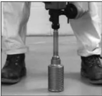
natural_image
Close-up of a mechanical tool with threaded shaft and base, held in hands (no visible text or symbols)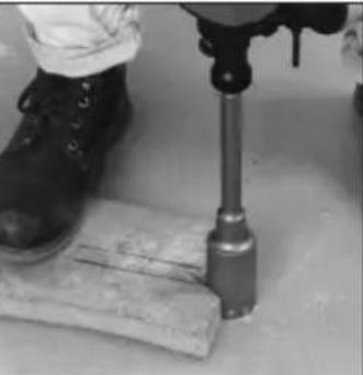
natural_image
Close-up of a person using a mechanical tool on a wooden surface, no visible text or symbolsnatural_image
Close-up of a circular stone or mineral sample with a dark tool inserted, no visible text or symbolsMilwaukee Tool (Canada) Ltd 1.800.268.4015
Monday-Friday, 7:00 AM - 4:30 PM CST www.milwaukeetool.ca
GARANTIE LIMITÉE- AUX ÉTATS-UNIS ET AU CANADA
natural_image
Pure technical line drawing of mechanical components without any text, numbers, or symbolsInsuficiente
natural_image
Pure technical line drawing of mechanical components without any text, numbers, or symbolsCorrecto
natural_image
Technical line drawing of a mechanical component with no visible text or symbolsDemasiado
natural_image
Close-up of a hand holding a mechanical tool with threaded shaft (no visible text or symbols)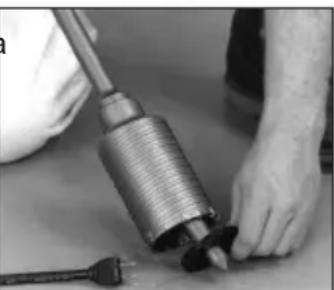
natural_image
Close-up of hands assembling a mechanical component with a coiled spring and plug (no visible text or symbols)natural_image
Close-up of a pipe with an arrow pointing left, against a textured wall (no text or symbols)natural_image
Close-up of a circular stone object with a wooden spoon inserted into it, resting on sandy ground (no visible text or symbols)Cincelar y triturar
Lunes a Viernes (9am a 6pm)
13135 West Lisbon Road
Brookfield, WI 53005 USA

- ⚠ WARNING Read all safety warnings, instructions, illustrations and specifica-
- WORK AREA SAFETY
- ELECTRICAL SAFETY
- PERSONAL SAFETY
- POWER TOOL USE AND CARE
- SERVICE
- SPECIFIC SAFETY RULES FOR ROTARY HAMMER
- EXTENSION CORDS
- GROUNDING
- Grounded Tools (Three-Prong Plugs)
- Double Insulated Tools (Two-Prong Plugs)
- ASSEMBLY
- Adjusting the Side Handle Position
- Setting the Depth Gauge
- Installing Bits and Chisels
- OPERATION
- Selecting Action
- Starting and Stopping
- ⚠ WARNING Applying greater pressure does not increase the tool's effectiveness.
- Operator Force
- Using the Control Switch
- Operating
- Cold Starting
- Using Rotary Percussion Core Bits
- Chiseling and Chipping
- MAINTENANCE
- Maintaining Tools
- Cleaning
- Repairs
- ACCESSORIES
- 1-800-SAWDUST (1.800.729.3878)
- SERVICE - CANADA
- Milwaukee Tool (Canada) Ltd 1.800.268.4015
- LIMITED WARRANTY USA & CANADA
- RÈGLES DE SÉCURITÉ GÉNÉRALES RELATIVES AUX OUTILS ELECTRIQUES
- AVERTISSEMENT
- CORDONS DE RALLONGE
- Démarrage et arrêt
- GARANTIE LIMITÉE- AUX ÉTATS-UNIS ET AU CANADA
- Cincelar y triturar
Brand : MILWAUKEE
Model : SDS 5359-21
Category : Hammer