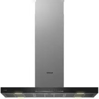
ADA 908 S - Basket Arçelik - Free user manual and instructions
Find the device manual for free ADA 908 S Arçelik in PDF.


| Brand | Arçelik |
| Model | ADA 908 S |
| Product type | Range hood |
| Use | External evacuation or internal recirculation (with optional charcoal filter) |
| Width | 90 cm (estimated based on model) |
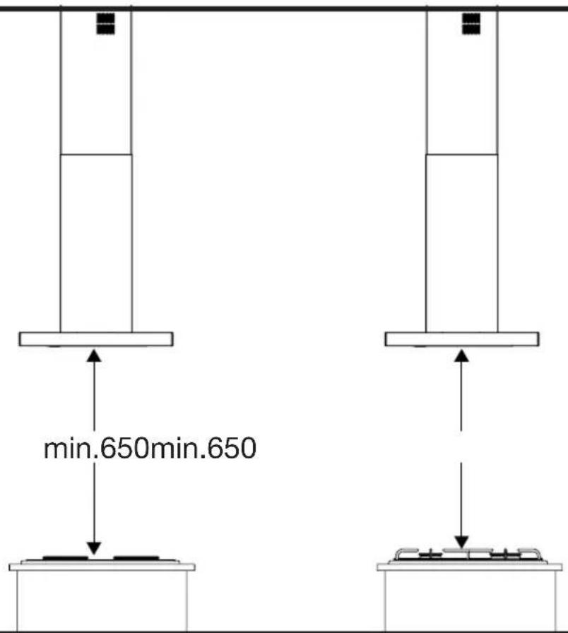
| Minimum height between hood and hob | 650 mm (gas and electric) |
| Recommended height | 650 to 750 mm |
| Air outlet diameter | 120 mm or 150 mm (adapter supplied) |
| Installation type | Ceiling (suspension) - requires support frame |
| Lighting | Integrated lighting |
| Oil filter (aluminium) | Dishwasher-safe or hand-washable |
| Charcoal filter | Optional, to be replaced every 4 months |
| Power supply | 220-240 V, 50 Hz |
| Controls type | Mechanical (buttons) |
| Approximate weight | 20 kg |
| Material | Stainless steel |
| Safety | Professional installation required, minimum distance, disconnect before maintenance |
| Repairability | Arçelik authorized service |
| Spare parts | Filters, bulbs, duct adapter |
Frequently Asked Questions - ADA 908 S Arçelik
User questions about ADA 908 S Arçelik
0 question about this device. Answer the ones you know or ask your own.
Ask a new question about this device
Download the instructions for your Basket in PDF format for free! Find your manual ADA 908 S - Arçelik and take your electronic device back in hand. On this page are published all the documents necessary for the use of your device. ADA 908 S by Arçelik.
USER MANUAL ADA 908 S Arçelik
Montaj Talimatları Installation Instructions Installationsanleitung Instructions d'installation Installatie instructies

natural_image
Icon of a crossed wrench and screwdriver (no text or symbols)TR / EN / DE / FR / NL
1
2
natural_image
Technical diagram of a mechanical assembly with a cylindrical component and internal structure, labeled '4a' on the left (no text or symbols within the diagram itself)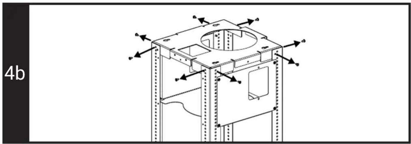
natural_image
Technical line drawing of a mechanical housing or enclosure with mounting holes and internal components, no text or symbols present.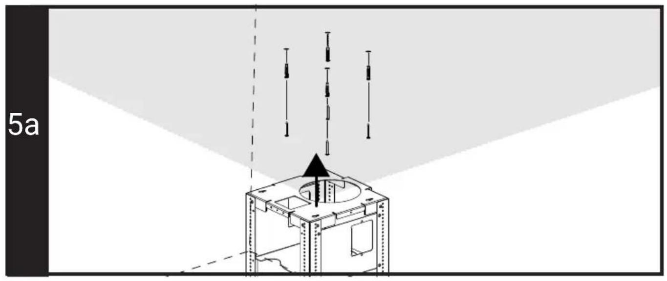
natural_image
Technical diagram of a mechanical lifting or mounting structure with a vertical frame and an upward arrow indicating motion (no text or symbols)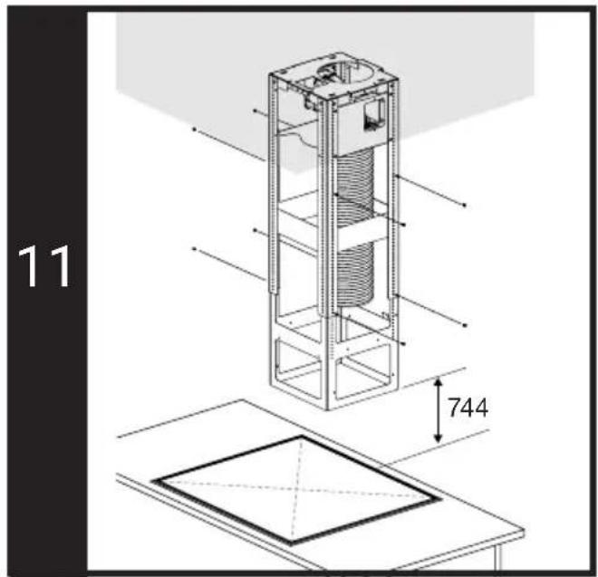
natural_image
Technical line drawing of a vertical cylindrical device with internal components and an upward arrow indicator (no text or symbols)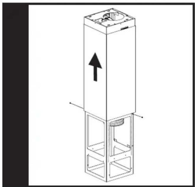
natural_image
Technical line drawing of a vertical cylindrical device with an upward arrow indicating direction (no text or symbols present)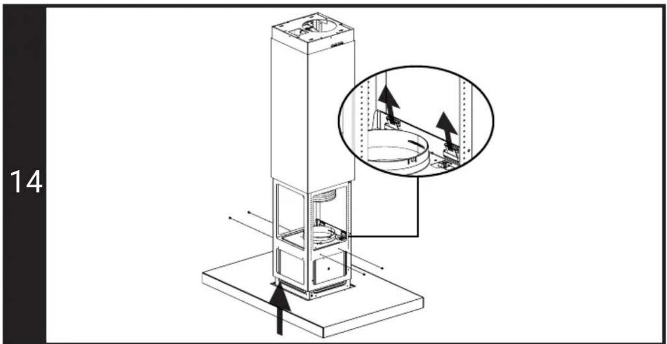
natural_image
Two isometric diagrams of a vertical industrial or storage unit with internal components and directional arrows, no text or symbols present.18
natural_image
Isometric line drawing of a vertical cylindrical structure with an upward arrow and internal components, mounted on a base (no text or symbols)19
20
EN - Safety Instructions
- The appliance shall be installed by a qualified person in accordance with the regulations in force to keep the warranty applicable. The manufacturer shall not be held responsible for damages arising from procedures carried out by unauthorized persons which will also void the warranty.
- It is customer's responsibility to prepare the location the appliance shall be placed on and to have the electrical installation prepared. Before calling Authorized Service, make sure the electrical infrastructure is suitable. If it is not, call a qualified electrician and fitter to have the required arrangements made.
- The rules specified in the local electrical installation standards shall be followed during the product installation.
- Before installing the appliance, remove all materials and documents in it and check for any damage on the appliance. Do not have it installed if the appliance is damaged.
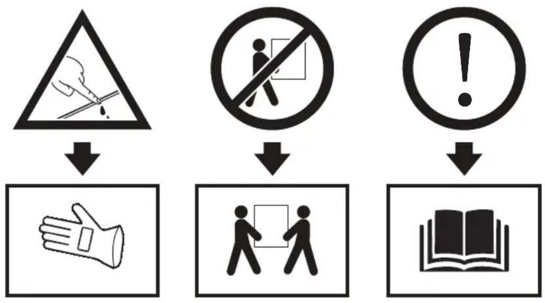
- The product is heavy, carry the product with at least two people.
- Disconnect electrical connections in the area of installation before starting the installation.
- Failing to install the screws and securing equipment in accordance with the guide may cause electrical danger.
- The parts of product may have sharp surfaces. Use protective gloves for installation.
- There may be a risk of fall if the product is not fixed enough. Make sure all fixings are securely fastened.
- Dimensions given in installation diagrams are in mm.
- The air to be expelled from the hood should not be fed into a flue used by other appliances burning gas or other fuels. (not applicable for appliances that discharge air back into the room).
- Legislation regarding the evacuation of air must be complied with.
- If the aluminium (oil) filters are not cleaned and maintained regularly and the carbon filter is not replaced even if its life is over (approximately 4 months), there is a possibility of fire.
Installation of the appliance
Installation can be made in 2 different ways according to the flue type of your product. You can determine the installation method suitable for your house and observe the following installation steps.
1- Installation with flue - the aspirated air is transferred to the outdoor through a flue; 2- Installation with a carbon filter where aspirated air will be transferred to the indoor by passing through a carbon filter
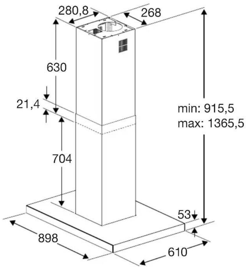
Product dimensions and safety measurements (Figure 1-2)
- Pay attention to the product dimensions. Consider its suitability with your furniture. (Figure 1) - Height between the bottom surface of your hood and the top surface of the hob should be no less than 650mm for gas ovens and 650mm for electrical ovens. (Figure 2) The maximum performance of the product can be achieved by leaving a height of 650 - 750mm between the hob and the hood. A gap of more than 750mm is not suitable for the performance of the product.
The inspection and preparation of the ceiling for the installation
- The ceiling on which the appliance will be installed, should be capable of bearing the appliance in a flat position.
- There should be no water, electricity and gas connections around the holes to be drilled in the ceiling to be installed.
Electrical connection of the appliance
- This appliance has a two-mark power cables and must be connected to the mains through an electrical switch with a gap of at least 3 mm between the bipolar contact terminals. Have the electrical connection done by a qualified electrician.
- Disconnect the appliance from the electric connection before starting any work on the electrical installation. Risk of electric shock.
- The appliance may only be connected to the mains electricity connection by an authorized and qualified person. The manufacturer shall not be held responsible for any damages that may occur as a result of operations performed by unauthorized persons.
• Install your appliance in a way that the electrical connection (power outlet, plug) can be easily reached after installation.
- If your product has plug, do not make electrical connections by disconnecting the plug during installation. Connections made by cutting off render the product warranty void and pose a danger to user safety.
1- Installation with flue - the aspirated air is transferred to the outdoor through a flue; Installation of hood carrier frames
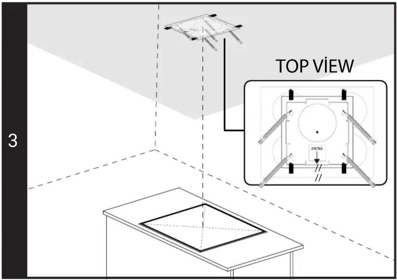
- Determine the centre point of your hob. Identify and mark the centre point of the trace drop on the ceiling at the exact alignment of the centre point. (You can make precise marking with the help of laser meter)
- Place the centre point of your supplied template installation paper at the point you marked on the ceiling. Tape the provided template to the ceiling by placing the part marked "Front" on the front side of your hob and in parallel with the alignment of your hob. Mark the screw fixing holes located on the template to the ceiling with a pencil, as shown in Figure 3.
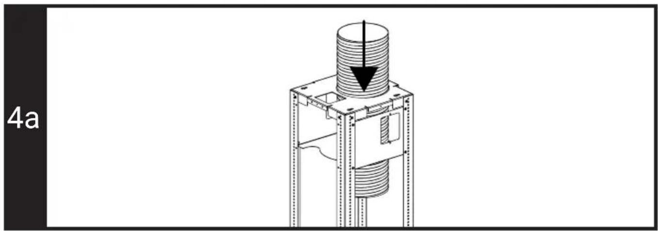
- Insert the flue outlet pipe previously inserted in the ventilation hole on the ceiling, through the hole on the frame from the top as shown in Figure 4a.
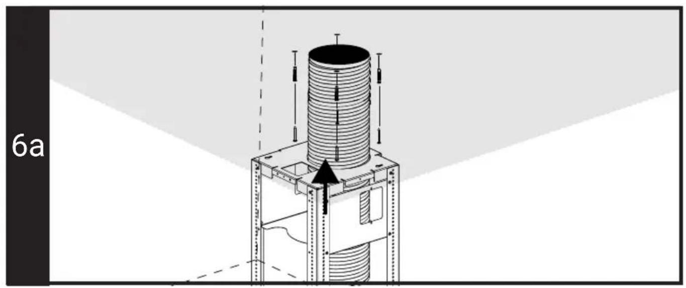
- Fix the dowels to the ceiling by drilling the 4 points you have marked. Drive 4 screws into the dowels so that the head is not fully seated. (Figure 5a-6a)
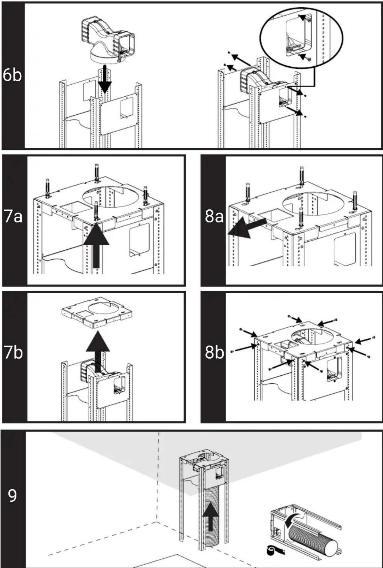
- Insert the upper carrier frame into the partially tightened screws through the large holes (Figure 7a). As shown in Figure 8a, pull the carrier frame forward to make it go through the small channel, screw it and fix by completely tightening on the dowels.
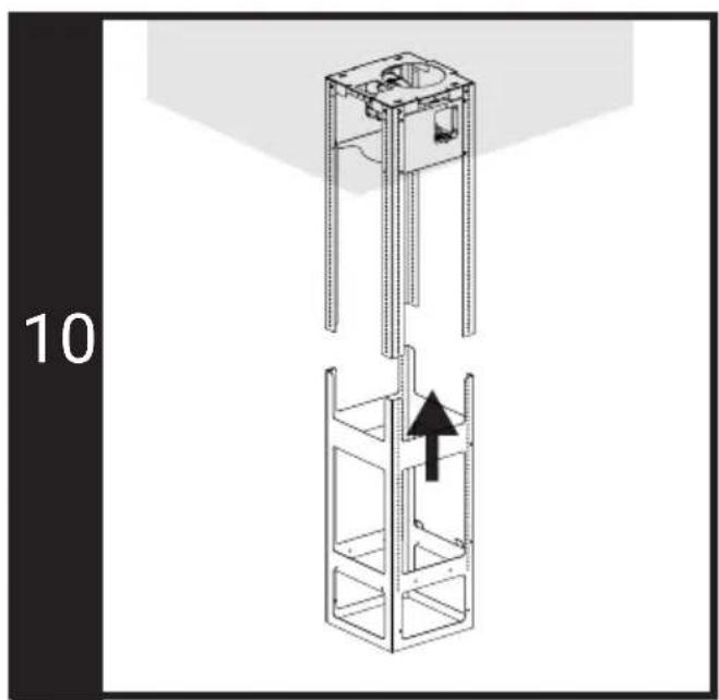
- Place the lower carrier frame on the upper carrier frame (Figure 10).
-
Align it so that there is at least 744 mm between the lowest surface of the bottom support frame and the top surface of your hob. Use 8 screws to fix through the holes where the lower and upper carrier frames correspond to each other. (Figure 11)
-
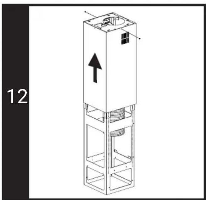
Insert the upper flue sheet in the lower part of the frame and fix it temporarily with 2 screws as shown in Figure 12.
- Insert the lower flue sheet in the lower part of the frame. Temporarily drive 2 screws into the holes on the frame from the bottom of the flue so that it does not fall (Figure 13).
- Insert the hood into the frame and insert the tabs into the slots on the frame as shown in Figure 14. Fix the hood to the frame with 4 screws.
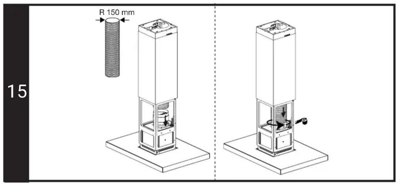
- Place the cover that prevents reverse air flow on the flue outlet as shown in Figure 15.
- If the diameter of your flue outlet pipe is 150 mm, place the flue outlet pipe on the cover (Figure 15).
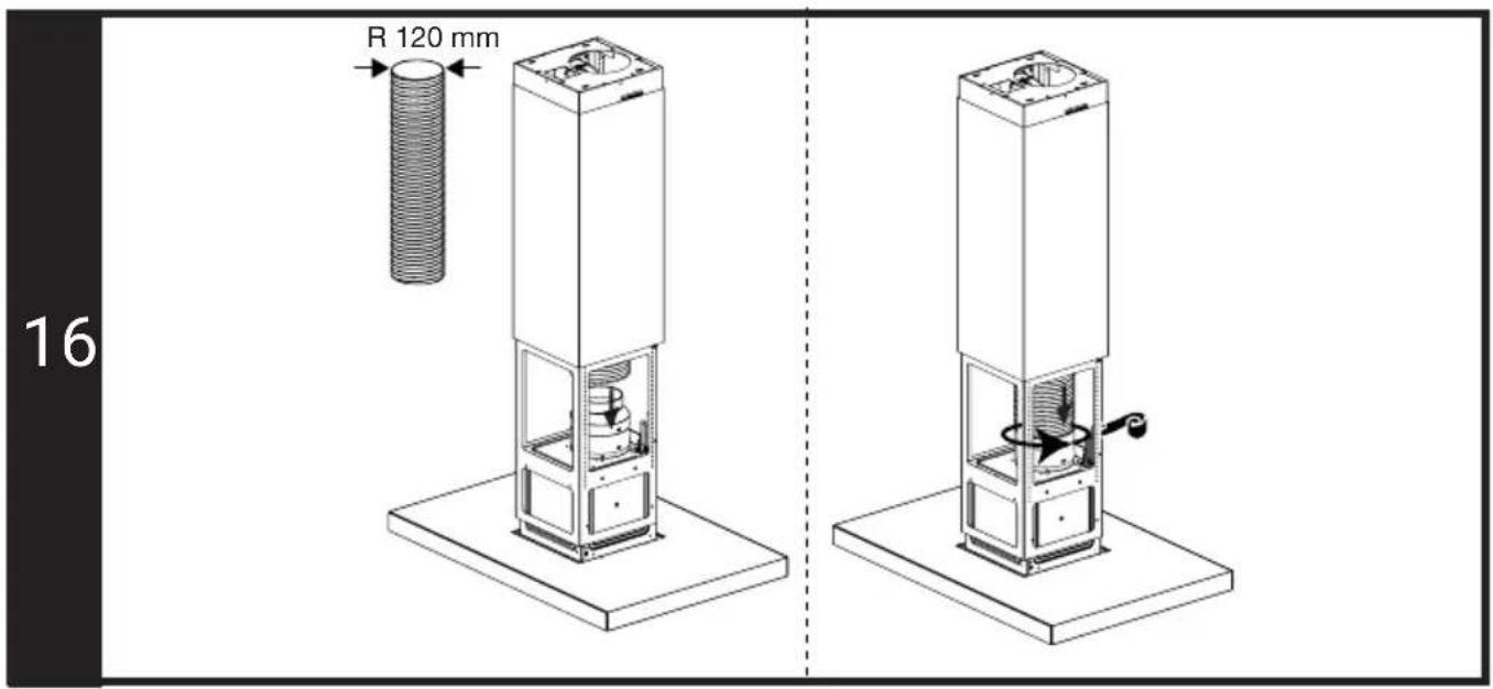
- If the diameter of your flue outlet pipe is 120 mm, mount the flue outlet pipe after placing the flue connection adapter on the cover. (Figure 16)
• Insulate the joints appropriately. - Remove the 2 screws holding the lower flue sheet temporarily and lower it into the hood body.
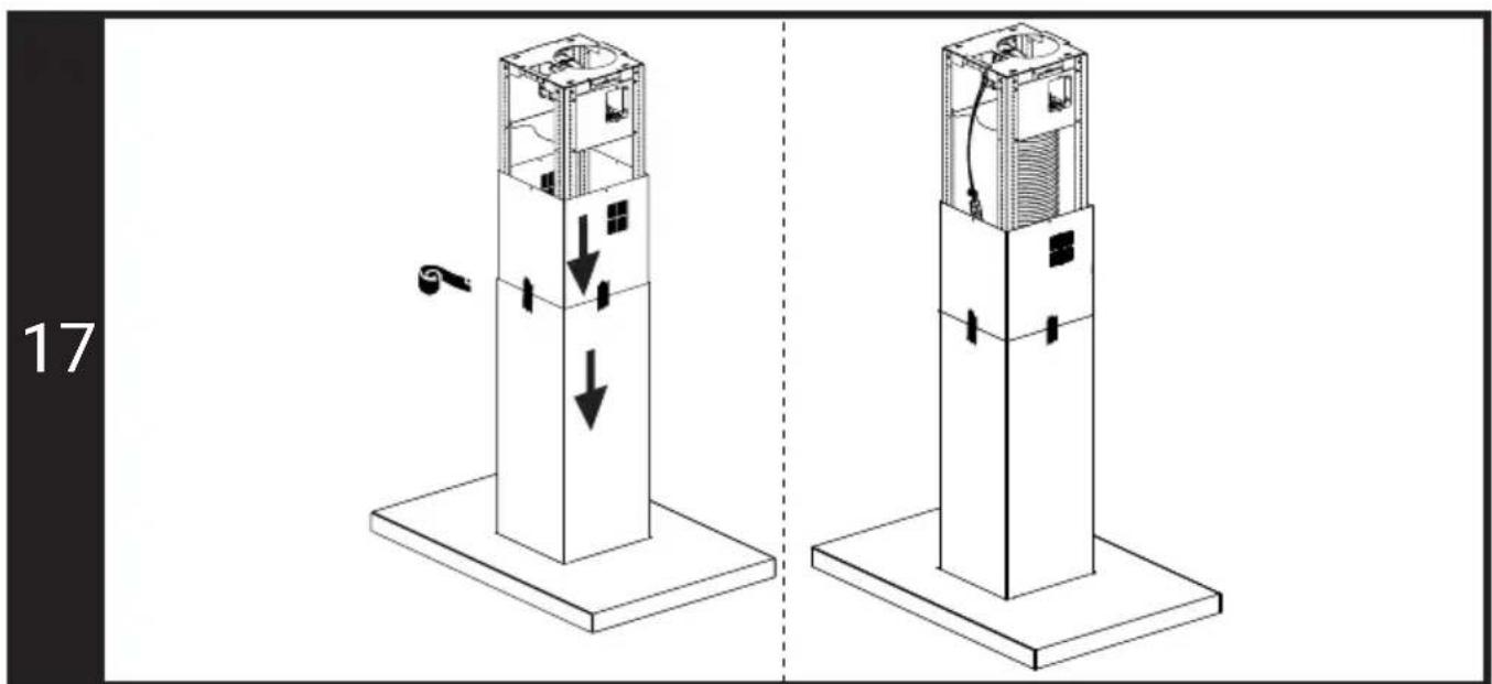
- Remove the 2 screws that temporarily hold the upper flue sheet. Lower it by holding it to the level where electrical connection can be made without dropping it completely into the lower flue sheet and temporarily fix it to the lower flue sheet with tapes so that it does not fall completely into the inner part. (Figure 17)
- Make the electrical connection.
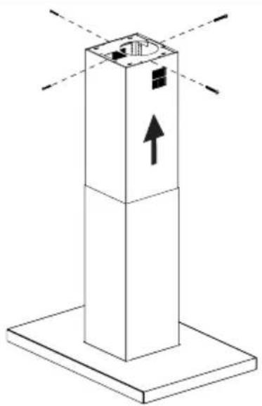
- Remove the tapes holding the upper flue sheet and pull it up so that it completely closes the frame and fix it with 4 screws as shown in Figure 18.
2- Installation with a carbon filter where aspirated air will be transferred to the indoor by passing through a carbon filter
- In the carbon filter installation, the air sucked from the environment passes through the aluminium (oil) filter and is purified from odours. After passing through the carbon filters and the air diverter, it is supplied back to the environment through the ventilation grilles on the side surface of the flue. Flue outlet pipes are not used in carbon filter installation.
- Determine the centre point of your hob. Identify and mark the centre point of the trace drop on the ceiling at the exact alignment of the centre point. (You can make precise marking with the help of laser meter)
- Place the centre point of your supplied template installation paper at the point you marked on the ceiling. Tape the provided template to the ceiling by placing the part marked "Front" on the front side of your hob and in parallel with the alignment of your hob. Mark the screw fixing holes located on the template to the ceiling with a pencil, as shown in Figure 3.
- To install the air guide plastic, remove the 8 screws on the upper carrier frame (Figure 4b) and remove the ceiling connection sheet.
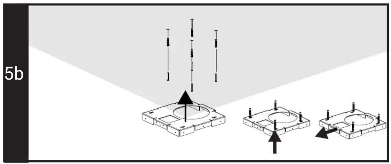
- Fix the dowels to the ceiling by drilling the 4 points you have marked. Drive 4 screws into the dowels so that the head is not fully seated. (Figure 5b)
- Insert the removed ceiling connection sheet through the partially screwed screws using the large holes. As shown in Figure 5b, pull it forward to make it go through the small channel, screw it and fix by completely tightening on the dowels.
- Insert the air baffle plastic into the slot on the top of the frame as shown in Figure 6b and fix it with 4 screws from the sides.
- Fit the upper frame into the ceiling connection part (Figure 7b). Use the 8 screws removed to fix the upper frame to the ceiling connection part. (Figure 8b)
- Place the lower carrier frame on the upper carrier frame (Figure 10).
- Align it so that there is at least 744 mm between the lowest surface of the bottom support frame and the top surface of your hob. Use 8 screws to fix through the holes where the lower and upper carrier frames correspond to each other. (Figure 11)
- Insert the upper flue sheet in the lower part of the frame and fix it temporarily with 2 screws as shown in Figure 12.
- Insert the lower flue sheet in the lower part of the frame. Temporarily drive 2 screws into the holes on the frame from the bottom of the flue so that it does not fall (Figure 13).
- Insert the hood into the frame and insert the tabs into the slots on the frame as
shown in Figure 14. Fix the hood to the frame with 4 screws.
- Place the cover that prevents reverse air flow on the flue outlet as shown in Figure 15.
- If the diameter of your flue outlet pipe is 150 mm, place the flue outlet pipe on the cover (Figure 15).
- If the diameter of your flue outlet pipe is 120 mm, mount the flue outlet pipe after placing the flue connection adapter on the cover. (Figure 16)
• Insulate the joints appropriately. - Remove the 2 screws holding the lower flue sheet temporarily and lower it into the hood body.
- Remove the 2 screws that temporarily hold the upper flue sheet. Lower it by holding it to the level where electrical connection can be made without dropping it completely into the lower flue sheet and temporarily fix it to the lower flue sheet with tapes so that it does not fall completely into the inner part. (Figure 17)
- Make the electrical connection.
- Remove the tapes holding the upper flue sheet and pull it up so that it completely closes the frame and fix it with 4 screws as shown in Figure 18.
Installation of carbon filter
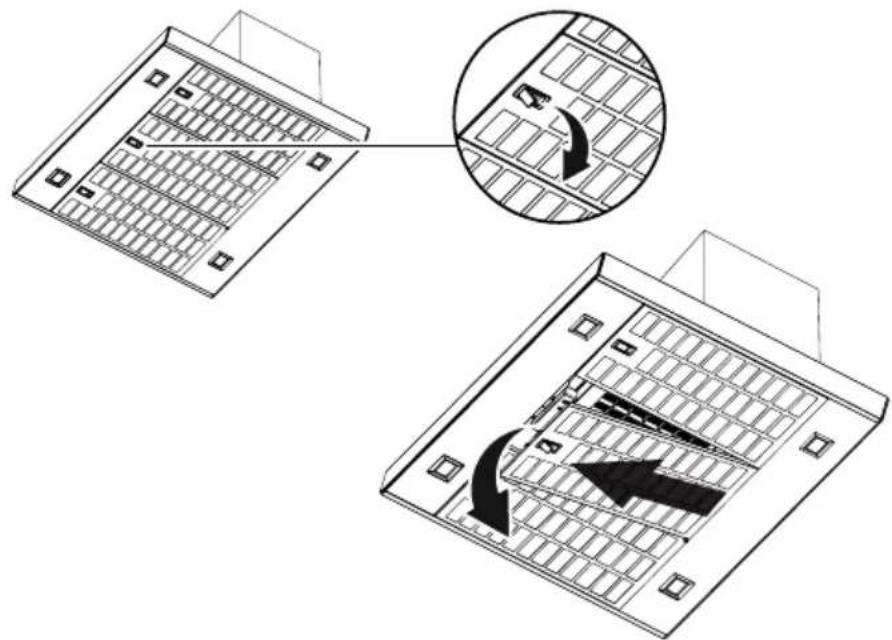
- The aluminium filters should be removed to install the carbon filter. Remove the aluminium (oil) filters as shown in figure 19.
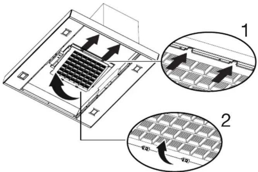
- First, place the tabs on the carbon filter into their slots as seen in figure 20 (1). Then, press the locks on the other end of the carbon filter upwards and attach them (2).
- Replace the aluminium (oil) filters and complete the installation.
Final check
- Check the hood and its lamp by operating them as described in the user manual.
- Montaj Talimatları Installation Instructions Installationsanleitung Instructions d'installation Installatie instructies
- EN - Safety Instructions
- Installation of the appliance
- Product dimensions and safety measurements (Figure 1-2)
- The inspection and preparation of the ceiling for the installation
- Electrical connection of the appliance
- 1- Installation with flue - the aspirated air is transferred to the outdoor through a flue; Installation of hood carrier frames
- 2- Installation with a carbon filter where aspirated air will be transferred to the indoor by passing through a carbon filter
- Installation of carbon filter
- Final check
Brand : Arçelik
Model : ADA 908 S
Category : Basket