
SRN3RG12UHD - Server Tripp Lite - Free user manual and instructions
Find the device manual for free SRN3RG12UHD Tripp Lite in PDF.

| Product Type | Rugged NEMA-3R SmartRack Wall-Mount Enclosure |
| Brand | Tripp Lite |
| Model | SRN3RG12UHD |
| Rack Units | 12U |
| Protection Rating | NEMA 3R (protection against rain, snow, dust, sleet) |
| Material | Rugged Steel |
| Color | Black (standard) |
| Height (mm) | 728 mm (28.65 in) |
| Width (mm) | 662 mm (26.06 in) |
| Depth (mm) | 918 mm (36.16 in) |
| Net Weight (kg) | 98.3 kg (216.84 lb) |
| Packaged Weight (kg) | 127 kg (280 lb) |
| Adjustable Mounting Depth | Yes, in 12.7 mm (1/2 in) increments |
| Lockable Doors | Front and rear, with keys provided |
| Cable Access | Bottom opening with removable panel |
| Max Conduit | Size 2, 2.5 in hole |
| Grounding | Threaded ground point with 8 AWG wire (included) |
| Warranty | 5-Year Limited |
| Recommended Use | Servers, network equipment, industrial control |
| Ventilation | Internal fans, clearance required front/rear/top |
Frequently Asked Questions - SRN3RG12UHD Tripp Lite
User questions about SRN3RG12UHD Tripp Lite
0 question about this device. Answer the ones you know or ask your own.
Ask a new question about this device
Download the instructions for your Server in PDF format for free! Find your manual SRN3RG12UHD - Tripp Lite and take your electronic device back in hand. On this page are published all the documents necessary for the use of your device. SRN3RG12UHD by Tripp Lite.
USER MANUAL SRN3RG12UHD Tripp Lite
- Important Safety Instructions 2
- Overview 2
- Feature Identification 3
- Enclosure Installation 4
4.1 Preparation 4
4.2 Unpacking 4
4.3 Ground Connection 5
- Enclosure Configuration 5
5.1 Door Locks 5
5.2 Cable Access and Management 5
5.3 Mounting Rails 6
5.4 Adjusting Mounting Rail Depth 6
- Wall Mounting the Enclosure 7
-
Equipment Installation 9
-
Specifications 9
8.1 Unit Dimensions 9
8.2 Package Dimensions 9
- Storage and Service 10
- Warranty and Product Registration 10
Español 11
Français 21
WARRANTY REGISTRATION
Register your product today and be automatically entered to win an ISOBAR ^® surge protector in our monthly drawing!
tripplite.com/warranty


Manufacturing Excellence.
1. Important Safety Instructions

SAVE THESE INSTRUCTIONS
This manual contains instructions and warnings that must be followed during the installation and operation of the product described in this manual. Failure to comply may invalidate the warranty and cause property damage or personal injury.
- The enclosure is extremely heavy. Use caution when handling the enclosure. Do not attempt to unpack, move or install it unassisted. Use a mechanical device such as a forklift or pallet jack to move the enclosure in the shipping container.
- Do not place any object on the enclosure, especially containers of liquid, and do not attempt to stack the enclosures.
- Inspect the shipping container and the enclosure for shipping damage. Do not use the enclosure if it is damaged.
- Leave the enclosure in the shipping container until it has been moved as close to the final installation location as possible.
- Leave adequate space at the front, rear, top and bottom of the enclosure for proper ventilation. Do not block, cover or insert objects into the external ventilation openings of the enclosure.
- For permanent wall mounting, be sure to securely fasten the enclosure to the building structure before operation.
- Use caution when cutting packing materials. The enclosure could be scratched, causing damage not covered by the warranty.
- Save all packing materials for later use. Repacking and shipping the enclosure without the original packing materials may cause product damage that will void the warranty.
- Use of this equipment in life support applications where failure of this equipment can reasonably be expected to cause the failure of the life support equipment or to significantly affect its safety or effectiveness is not recommended.
- This enclosure supports a maximum Conduit Trade Size 2 with a 2.5 inch hole.
- Use only NEMA-3R (or higher) rated conduit/fittings to maintain the enclosure's environmental protection rating.
2. Overview
Side-mount, static, heavy-duty, wall-mounted NEMA 3R enclosures accommodate all standard 19-inch rack-mount equipment, regardless of vendor, and ship fully assembled for quick and easy deployment. They have a NEMA 3R rating for protection against falling dirt, rain, sleet, snow, windblown dust, splashing water, hose-directed water and external formation of ice. These adaptable, heavy-duty cabinets come in two heights and have variable mounting depths, making them ideal for servers. They include removable, lockable front and rear doors.
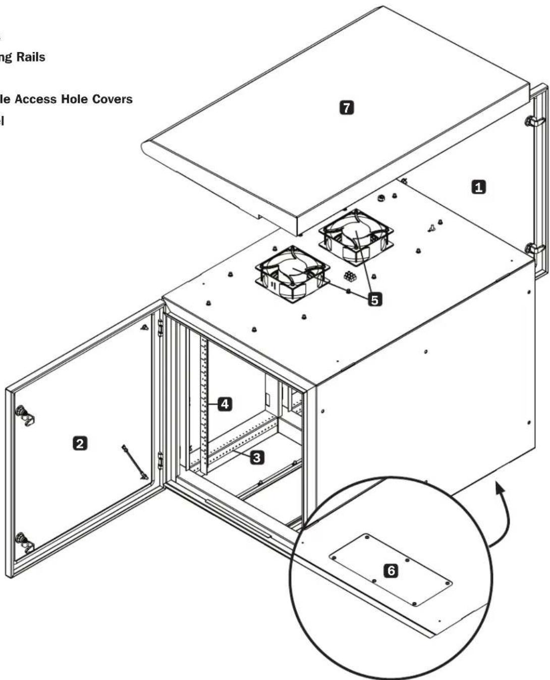
3. Feature Identification
Model SRN3RG12UHD is shown. The SRN3RG18UHD has similar features, with the only differences being rack height.
1 Rear Door
2 Front Door
3 Horizontal Rails
4 Vertical Mounting Rails
5 Internal Fans
6 Removable Cable Access Hole Covers
7 Fan Cover Panel
4. Enclosure Installation

Caution! Read All Instructions and Warnings Before Installation!

Warning: Rack enclosures can be extremely heavy. Do not attempt to unpack, move or install the enclosure without assistance. Use extreme caution when handling the enclosure and be sure to follow all handling and installation instructions. Do not attempt to install equipment without first stabilizing the enclosure.
4.1 Preparation
The enclosure must be installed in a structually sound area that is able to bear the weight of the enclosure, all the equipment that will be installed in the enclosure and any other enclosures and/or equipment that will be installed nearby. Before unpacking the enclosure, you should transport the shipping container closer to the final installation location to minimize the distance you will need to move the unit after the protective packaging has been removed. If you plan to store the enclosure for an extended period before installation, follow the instructions in the Storage and Service section.
You need several tools:
You also need the following hardware:
- Level
- Appropriate hardware for wall mounting (not included)
• Phillips-head screwdriver
• Appropriate tools for wall mounting
4.2 Unpacking

Use at least two people to unpack the enclosure.
1 Move shipping pallet to a firm, level surface.
2 Open box and remove the four foam corner protectors. Save all packing materials for later use unless you are certain they will not be required. Packing materials are recyclable.
3 With one person on each side, carefully lift the enclosure out of the box and place on a firm, level surface.
4 Examine the enclosure for any damage or loose parts. Confirm all parts are present. If anything is missing or damaged, contact Tripp Lite for assistance. Do not attempt to use the enclosure if it has been damaged.

Never extend more than one component from the enclosure at a time.


Warning: Never attempt to lift or install without adequate help. Do not try lifting the enclosure alone.
4. Enclosure Installation
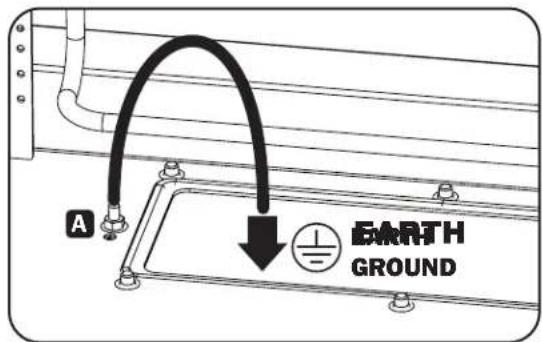
4.3 Ground Connection
All parts of the enclosure are grounded to the frame of the enclosure. Use the enclosure's rear threaded grounding point A and an M6 hex nut and washer (included) to connect the frame of the enclosure directly to your facility's earth ground connection with an 8 AWG (3.264 mm) wire. Route the ground wire under the enclosure's frame to ensure unhindered door operation. Warning: Attach each enclosure to earth ground separately. Do not use the enclosure without an earth ground connection.
5. Enclosure Configuration
Before installation, be sure to plan the location and arrangement of components within the enclosure. Be sure all mounting rails are reversed or adjusted for depth, depending on your equipment configuration.
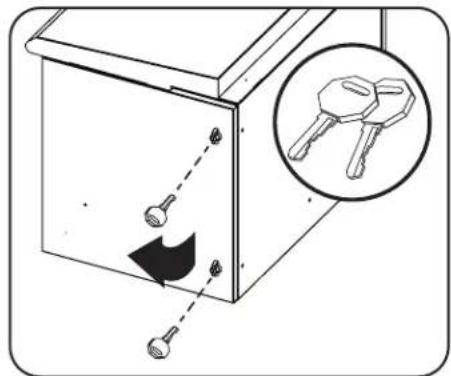
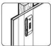
5.1 Door Locks
The front and rear doors have locks that can be opened with the included keys.
natural_image
Diagram of a cabinet with arrows indicating movement, showing key inserted into the door and a magnified inset showing two keys (no text or symbols present)5.2 Cable Access and Management
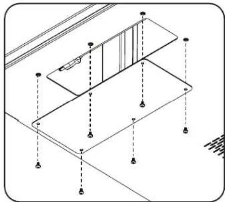
The bottom of the enclosure has an opening for cable access and management. The opening can be closed by screwing in the removable cable access panel.
natural_image
Isometric architectural diagram of a multi-level building structure with vertical supports and horizontal beams (no text or symbols)5. Enclosure Configuration
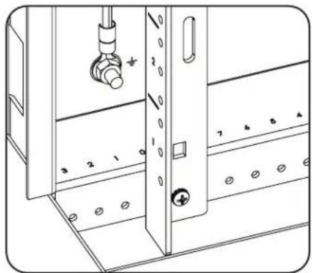
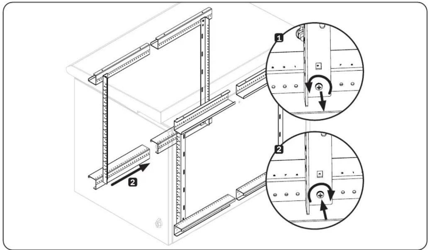
5.3 Mounting Rails
The enclosure comes with mounting rails that have tapped holes for mounting rack equipment. To install equipment, use the included hardware. Warning: Be sure to have the enclosure securely mounted to the wall, or in its final position on the floor, before mounting any equipment inside. Also be sure to have all the right adjustments on your rails before mounting equipment. (See below for Adjusting Mounting Rail Depth.)
natural_image
Technical line drawing of a mechanical assembly with numbered components (no text or symbols)5.4 Adjusting Mounting Rail Depth
Warning: Do not attempt to adjust rails while equipment is installed in the enclosure. Do not attempt to use rails without screws installed (2 per rail).
The preset mounting depth varies based on the model. Do not adjust the mounting rails unless your equipment requires a different mounting depth. The front set of rails can be adjusted independently in 1/2 inch (12.7 mm) increments.
1 Each equipment mounting rail is connected to the enclosure with 2 screws: 1 in the upper corner and another in the lower corner. Using a Phillips-head screwdriver, remove the screws that fasten the rails to the enclosure.
2 Slide the mounting rails to the desired depth and reattach them using the screws you removed in Step 1.
6. Wall Mounting the Enclosure
1. Mount the enclosure to wall studs

Warning: Never attempt to lift or install without adequate help. Do not try lifting the enclosure alone.


Do not attempt to mount the enclosure to the wall with equipment in the enclosure.


The supporting surface must be able to safely support the combined load of the equipment and all attached hardware and components. For the actual weight, size and load capacity of the enclosure, view the product specifications and other support resources at tripplite.com/support.

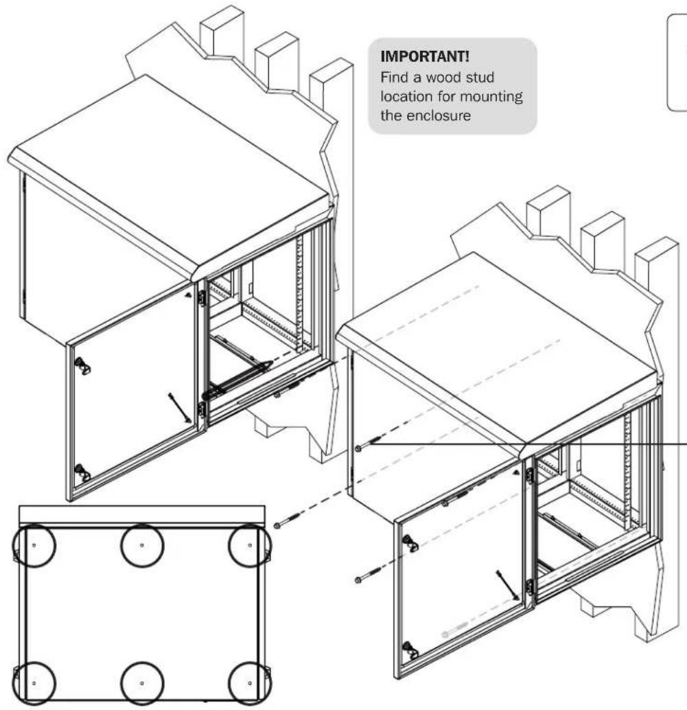
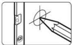
Mark the exact location of the mounting holes
Drill pilot holes
(Mounting Hardware Not Included)
Attach the enclosure onto the wall
6. Wall Mounting the Enclosure
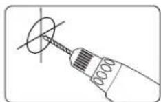
- Enclosure must be installed by a qualified technician. Before mounting, use a level and tape measure to position your mounting area precisely. Use a minimum of four screws (not included, sizes will vary by model) to secure the enclosure in place. A fender washer with close cell foam is provided with the cabinet. The close cell foam side of the washer should be against the cabinet to seal the mounting hole.
• Make sure mounting screws are anchored into the center of the studs. Use of a stud finder is highly recommended. - If there is no stud at the mounting location, it is recommended you install studs at the desired location to secure the enclosure in place. DO NOT use plastic expansion wall anchors, threaded drywall anchors, threaded drywall toggles, sleeve-type hollow wall anchors (a.k.a. molly bolts) or toggle bolts, due to the weight of the enclosure.
- Use suitable mounting means when installing to cinder block, concrete, or wood studs. It is the installer's responsibility to choose suitable mounting hardware (not supplied). Do NOT use plastic expansion wall anchors, threaded drywall anchors, threaded drywall toggles, sleeve-type hollow wall anchors (a.k.a. molly bolts) or toggle bolts, due to the weight of the enclosure.
- If placing the enclosure over a telecommunications receptacle, remove the wall plate, then fasten the enclosure to the wall. Once secured, fasten the wall plate over the receptacle.
- If no telecommunications receptacle is available, a surface mount box (or biscuit jack) and equipment cord can be mounted inside the unit.
-
Use an adhesive-backed surface mount box.
-
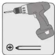
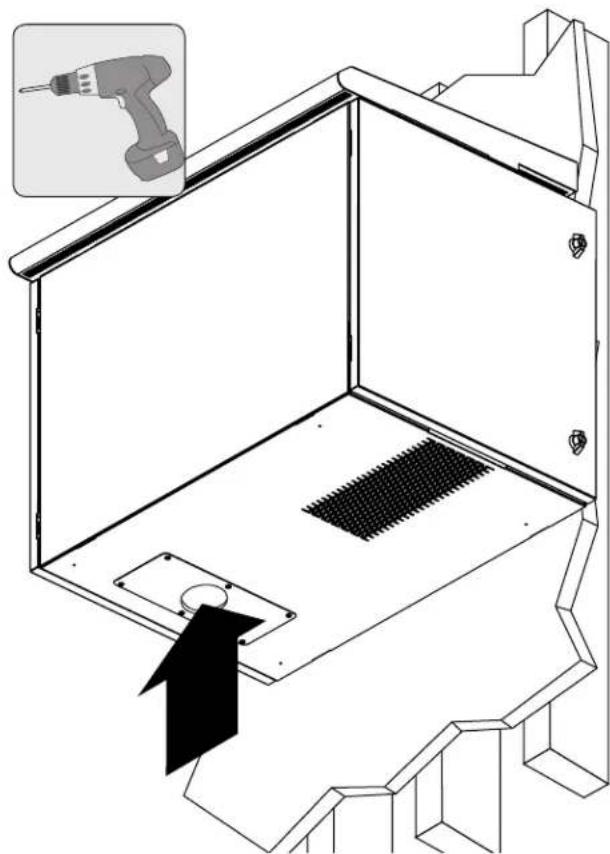
Use a Drill and Punch (Such as a Greenlee) to Create a Bottom Conduit Cutout
natural_image
Technical line drawing of a mechanical device with a tool inserted, showing internal components and a magnified inset (no text or symbols)Note: This conduit cover supports a maximum Conduit Trade Size 2 with 2.5" hole.
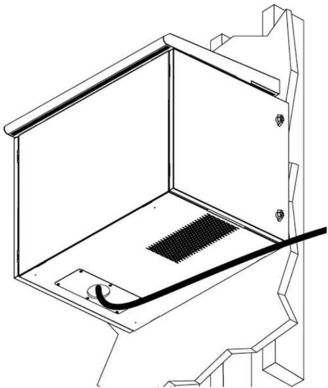
- Run Data and Power Cable (If Required) Through the Conduit Cutout
natural_image
Technical line drawing of a mechanical or architectural component with no visible text or symbolsNote: To maintain a NEMA rating, use sealed fittings in the cutouts when connecting to conduit. Accessory gland plates with model numbers SRGP1KO, SRGP2KO, SRGP3RM and SRGP4PLASTIC are available (sold separately).
7. Equipment Installation
Warning: Do not install equipment until you have stabilized the enclosure. Install heavier equipment first and install it towards the bottom of the enclosure. Install equipment starting from the bottom of the enclosure and proceeding toward the top of the enclosure—never the reverse. If using sliding equipment rails, be careful when extending the rails. Do not extend more than one set of sliding equipment rails at one time. Avoid extending sliding equipment rails near the top of the enclosure.
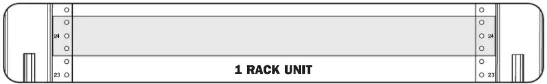
Note: The tapped holes in the middle of each rack unit are numbered and also include a small notch to aid identification. A single rack unit includes the space occupied by the numbered hole and the holes directly above and below.
8. Specifications
8.1 Unit Dimensions
| MODEL SRN3RG12UHD SRN3RG18UHD | ||
| HEIGHT | 28.65 in.(728 mm) | 39.15 in.(994 mm) |
| WIDTH | 26.06 in.(662 mm) | 26.06 in.(662 mm) |
| DEPTH | 36.16 in.(918 mm) | 36.16 in.(918 mm) |
| WEIGHT | 216.84 lb.(98.3 kg) | 259.55 lb.(117.7 kg) |
8.2 Package Dimensions
| MODEL SRN3RG12UHD SRN3RG18UHD | ||
| HEIGHT | 34.50 in.(878.3 mm) | 45.00 in.(1143 mm) |
| WIDTH | 30.00 in.(762 mm) | 30.00 in.(762 mm) |
| DEPTH | 40.50 in.(1,028.7 mm) | 40.50 in.(1,028.7 mm) |
| WEIGHT | 280.00 lb.(127.00 kg) | 320.00 lb.(145.20 kg) |
9. Storage and Service
Storage
The enclosure should be stored in a controlled indoor environment, away from moisture, temperature extremes, flammable liquids and gasses, conductive contaminants, dust and direct sunlight. Store the enclosure in its original shipping container if possible.
Service
Your Tripp Lite product is covered by the warranty described in this manual. A variety of Extended Warranty and On-Site Service Programs are also available from Tripp Lite. For more information on service, visit tripplite.com/support. Before returning your product for service, follow these steps:
- Review the installation and operation procedures in this manual to insure that the service problem does not originate from a misreading of the instructions.
- If the problem continues, do not contact or return the product to the dealer. Instead, visit tripplite.com/support.
- If the problem requires service, visit tripplite.com/support and click the Product Returns link. From here you can request a Returned Material Authorization (RMA) number, which is required for service. This simple on-line form will ask for your unit's model and serial numbers, along with other general purchaser information. The RMA number, along with shipping instructions will be emailed to you. Any damages (direct, indirect, special or consequential) to the product incurred during shipment to Tripp Lite or an authorized Tripp Lite service center is not covered under warranty. Products shipped to Tripp Lite or an authorized Tripp Lite service center must have transportation charges prepaid. Mark the RMA number on the outside of the package. If the product is within its warranty period, enclose a copy of your sales receipt. Return the product for service using an insured carrier to the address given to you when you request the RMA.
10. Warranty and Product Registration
5-Year Limited Warranty
Seller warrants this product, if used in accordance with all applicable instructions, to be free from original defects in material and workmanship for a period of 5 years from the date of initial purchase. If the product should prove defective in material or workmanship within that period, Seller will repair or replace the product, in its sole discretion.
THIS WARRANTY DOES NOT APPLY TO NORMAL WEAR OR TO DAMAGE RESULTING FROM ACCIDENT, MISUSE, ABUSE OR NEGLECT. SELLER MAKES NO EXPRESS WARRANTIES OTHER THAN THE WARRANTY EXPRESSLY SET FORTH HEREIN. EXCEPT TO THE EXTENT PROHIBITED BY APPLICABLE LAW, ALL IMPLIED WARRANTIES, INCLUDING ALL WARRANTIES OF MERCHANTABILITY OR FITNESS, ARE LIMITED IN DURATION TO THE WARRANTY PERIOD SET FORTH ABOVE; AND THIS WARRANTY EXPRESSLY EXCLUDES ALL INCIDENTAL AND CONSEQUENTIAL DAMAGES. (Some states do not allow limitations on how long an implied warranty lasts, and some states do not allow the exclusion or limitation of incidental or consequential damages, so the above limitations or exclusions may not apply to you. This warranty gives you specific legal rights, and you may have other rights which vary from jurisdiction to jurisdiction).
WARNING: The individual user should take care to determine prior to use whether this device is suitable, adequate or safe for the use intended. Since individual applications are subject to great variation, the manufacturer makes no representation or warranty as to the suitability or fitness of these devices for any specific application.
Product Registration
Visit tripplite.com/warranty today to register your new Tripp Lite product. You'll be automatically entered into a drawing for a chance to win a FREE Tripp Lite product!*
* No purchase necessary. Void where prohibited. Some restrictions apply. See Web site for details.
Tripp Lite follows a policy of continuous improvement. Product specifications are subject to change without notice. Photos and illustrations may differ slightly from actual products.


1111 W. 35th Street, Chicago, IL 60609 USA • tripplite.com/support
21-02-099 933E08 RevA
natural_image
Diagram of a door lock with a key inserted, showing an arrow indicating left-hand rule (no text or symbols present)natural_image
Isometric architectural diagram showing a staircase with vertical supports and horizontal beams (no text or symbols)natural_image
Technical line drawing of a mechanical assembly with numbered components (no text or symbols)natural_image
Technical line drawing of a mechanical device with a tool inserted, showing internal components and a magnified inset (no text or symbols)natural_image
Technical line drawing of a mechanical or architectural component with no visible text or symbols1111 W. 35th Street, Chicago, IL 60609 EE UU • tripplite.com/support
21-02-099 933E08 RevA
natural_image
Diagram of a door lock with a key inserted, showing internal components and a magnified inset of key details (no text or symbols present)natural_image
Isometric architectural diagram of a two-story building facade with vertical supports and horizontal beams (no text or symbols)natural_image
Technical line drawing of a mechanical assembly with numbered components (no text or symbols)natural_image
Technical line drawing of a mechanical or architectural component with a central grid and curved base (no text or symbols)1111 W. 35th Street, Chicago, IL 60609 USA • tripplite.com/support
- WARRANTY REGISTRATION
- Important Safety Instructions
- SAVE THESE INSTRUCTIONS
- Overview
- Feature Identification
- Enclosure Installation
- Caution! Read All Instructions and Warnings Before Installation!
- Preparation
- Unpacking
- Use at least two people to unpack the enclosure.
- Never extend more than one component from the enclosure at a time.
- Warning: Never attempt to lift or install without adequate help. Do not try lifting the enclosure alone.
- Ground Connection
- Enclosure Configuration
- Door Locks
- Cable Access and Management
- Mounting Rails
- Adjusting Mounting Rail Depth
- Wall Mounting the Enclosure
- Mount the enclosure to wall studs
- Equipment Installation
- Specifications
- Storage and Service
- Storage
- Service
- Warranty and Product Registration
- 5-Year Limited Warranty
- Product Registration
Brand : Tripp Lite
Model : SRN3RG12UHD
Category : Server