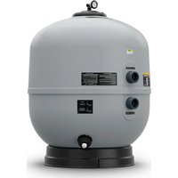
SFSM-60 - Water filter Jandy - Free user manual and instructions
Find the device manual for free SFSM-60 Jandy in PDF.


| Product Type | High-capacity sand filter for swimming pool |
| Brand | JANDY |
| Model | SFSM-60 |
| Filtration area | 0.29 m² (3.15 ft²) |
| Maximum flow rate | 238 L/min (63 GPM) |
| Maximum service pressure | 3.45 bar (50 psi) |
| Total height (H) | 86.3 cm (34 in) |
| Diameter (D) | 66.0 cm (26.0 in) |
| Empty weight | 31.8 kg (70 lb) |
| Tank material | Reinforced plastic |
| Compatible valve type | Multi-port valve (BWVL-MPV-75), slide valve (BWVL-SLD-75) or Never Lube valve (BWVL-NVL-75) |
| Recommended filter media | #20 silica sand (0.4–0.5 mm) or sand + fine gravel |
| Sand capacity (sand only) | 170 kg (375 lb) |
| Sand + gravel capacity | 136 kg sand + 34 kg gravel |
| Backwash function | Yes – integrated via compatible valve |
| Automatic air purge | Yes: air release valve and automatic vent tube |
| Pressure gauge | Included with clean/dirty lock ring |
| Inlet/outlet connections | Two union fittings with O-rings |
| Maintenance | Regular backwashing; seasonal chemical cleaning possible |
| Safety | Air release valve; max pressure 3.45 bar; do not exceed 40 °C |
| Use | For swimming pool or spa only |
| Spare parts | Available: see exploded view in manual |
Frequently Asked Questions - SFSM-60 Jandy
User questions about SFSM-60 Jandy
0 question about this device. Answer the ones you know or ask your own.
Ask a new question about this device
Download the instructions for your Water filter in PDF format for free! Find your manual SFSM-60 - Jandy and take your electronic device back in hand. On this page are published all the documents necessary for the use of your device. SFSM-60 by Jandy.
USER MANUAL SFSM-60 Jandy
FOR YOUR SAFETY – This product must be installed and serviced by a contractor who is licensed and qualified in pool equipment by the jurisdiction in which the product will be installed where such state or local requirements exist. The maintainer must be a professional with sufficient experience in pool equipment installation and maintenance so that all of the instructions in this manual can be followed exactly. Before installing this product, read and follow all warning notices and instructions that accompany this product. Failure to follow warning notices and instructions may result in property damage, personal injury, or death. Improper installation and/or operation may void the warranty.

Improper installation and/or operation can create unwanted electrical hazard which may cause serious injury, property damage, or death.
ATTENTION INSTALLER – This manual contains important information about the installation, operation and safe use of this product. This information should be given to the owner/operator of this equipment.
Table of Contents
Section 1. Important Safety Instructions......3
1.1 Safety Instructions ....3
Section 2. Getting Started....4
2.1 Package Contents......4
2.2 Jandy Valve ^® Compatibility ....4
2.3 Required Tools/Equipment....4
2.4 Specifications And Dimensions ....5
2.5 Function 6
2.6 Equipment Location....6
Section 3. Setup....8
3.1 Install Pressure Gauge 8
3.2 Plumbing 9
3.3 Fill the Filter 9
3.4 Install The Filter Lid 11
Section 4. Startup And Operation .... 12
4.1 Startup 12
4.2 Operation....13
4.3 Draining the Filter and Removing the Filter Sand....15
Section 5. Maintenance....16
5.1 General Maintenance....16
5.2 Pressure Gauge....17
5.3 Winterizing....17
Section 6. Troubleshooting .... 17
Section 7. Performance....18
Section 8. Product Specifications and Technical Data ....19
8.1 Exploded Views....19
SAVE THESE INSTRUCTIONS
EQUIPMENT INFORMATION RECORD
DATE OF INSTALLATION
INSTALLER INFORMATION
INITIAL PRESSURE GAUGE READING (WITH CLEAR FILTER)
PUMP MODEL
HORSEPOWER
NOTES
Section 1. Important Safety Instructions
READ AND FOLLOW ALL INSTRUCTIONS
1.1 Safety Instructions
WARNING
MAXIMUM OPERATING PRESSURE OF THE FILTER IS 50 PSI.
NEVER SUBJECT THE FILTER TO ANY OPERATING PRESSURE EXCEEDING 50 PSI.
- Do not connect the system to an unregulated city water system or other external source of pressurized water producing pressures greater than 35 PSI.
- This filter operates under high pressure. When any part of the circulating system, i.e., filter, pump, valve(s), etc. is serviced, air can enter the system and become pressurized when the system is restarted.
- Pressurized air in a system can cause product failure or also cause the filter lid to be blown off which can result in death, serious personal injury or property damage. Ensure that all air is out of the system before operating the equipment.
- To minimize risk of severe injury or death, the filter and/or pump should not be subjected to the piping pressurization test. Local codes may require the pool piping system to be subjected to a pressure test. These requirements are generally not intended to apply to the pool equipment such as filters or pumps. Jandy pool equipment is pressure tested at the factory. If however, this WARNING cannot be followed and pressure testing of the piping system must include the filter and/or pump BE SURE TO COMPLY WITH THE FOLLOWING SAFETY INSTRUCTIONS.
- Check all clamps, bolts, lids, locking devices and system accessories to ensure they are properly installed and secured before testing.
- RELEASE ALL AIR in the system before testing.
• Water pressure for test must NOT EXCEED 35 PSI.
• Water temperature for test must NOT EXCEED 100°F (38°C). - Limit test to 24 hours. After test, visually check system to be sure it is ready for operation.
NOTICE: These parameters apply only to Jandy equipment. For non-Jandy equipment, consult the equipment manufacturer.
WARNING
To avoid electrical shock hazard, which can result in serious injury or death:
- Ensure that all electrical to the system is turned off before approaching, inspecting or troubleshooting any leaking valves or plumbing that may have caused other electrical devices in the surrounding area to get wet.
• Water discharged from an improperly positioned filter or valve can create an electrical hazard which can cause death, serious injury or property damage. - Improper dial valve installation can cause product failure or also cause the filter dial to be blown off, which can result in death, serious personal injury or property damage.
- Never attempt to adjust or remove the dial valve when the pump is running or there is pressure in the system. this can cause product failure or also cause the filter dial to be blown off, which can result in death, serious personal injury or property damage.
CAUTION
- Maintain your pressure gauge in good working order. The pressure gauge is the primary indicator of how the filter is operating.
- Creating high vacuum levels can cause the tank vessel to crack and leak with the potential for property damage.
- Be sure that all provisions for waste water disposal meet local, provincial or national codes. During any backwash or draining process, 100 gallons or more of water will be discharged. Do not discharge water where it will cause flooding or damage.
- To avoid damaging the laterals (spokes), slowly add the filter media until the laterals are fully covered. Consult Installation and Operation Manual for complete sand filling instructions. Cracked or broken laterals (spokes) will cause sand to be discharged to the pool.
CAUTION
- Use equipment only in a pool or spa installation.
- Before repositioning valve(s) and before beginning the assembly, disassembly, removal or adjustment of the lid, or any other service of the circulating system: (A) turn the pump off and shut off any automatic controls to ensure the system is not inadvertently started during servicing (B) open the air release valve. (C) wait until all pressure is relieved (air will have stopped flowing from the air release valve).
- When installing the threaded lid follow Setup section, Install the Filter Lid in this manual.
- Once service on the circulation system is complete, follow the Startup And Operation section of this manual.
- Maintain circulation system properly. Replace worn or damaged parts immediately.
- Be sure that the filter is properly mounted and positioned according to these installation instructions.
- Do not pressure test above 35 PSI. Pressure testing must be done by a trained pool professional. Use equipment only in a pool or spa installation.
Section 2. Getting Started
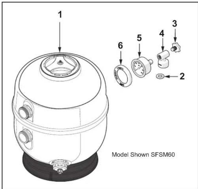
2.1 Package Contents
Unpack and check contents. If any parts are missing or damaged please call Customer Support at 1-800-822-7933 or productsupport@fluidra.com.
| Item Description Qty. | |
| 1* Filter Tank + Lid 1 | |
| 2 Gasket 1 | |
| 3 Vent Plug 1 | |
| 4 Tee 1 | |
| 5 Pressure Gauge | 1 |
| 6 Clean/Dirty Snap Ring | 1 |
| * O-Rings come installed from the factory. Please inspect to ensure the O-Ring is installed and properly seated before installation. | |
| **Filter tank comes fully assembled with lateral and diffuser internals. No internal assembly is required. | |
2.2 Jandy Valve ^® Compatibility
Jandy SFSM filters require a compatible backwash valve. See table below.
| Valve Type | Part No. |
| Multiport Valve | BWVL-MPV-75 |
| Slide Valve | BWVL-SLD-75 |
| Never Lube® Valve | BWVL-NVL-75 |
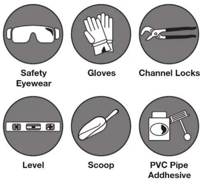
2.3 Required Tools/Equipment
The following list of equipment should be present and available to the installer at the time of install. Failure to use the appropriate safety and installation equipment could lead to personal injury or property damage.
2.4 Specifications And Dimensions
2.4.1 Specifications
| Specification SFSM60 | SFSM100SFSM100F | SFSM120SFSM120F | SFSM140SFSM140F | |||||
| Filtration Area | ft^2 3.15 0.29 | m^2 5.00 0.46 | ft^2 5.90 0.55 7.06 | m^2 0.65 | ft^2 | ft^2 | m^2 | |
| Max Flow Rate | gpm lpm63 238 | gpm lpm100 375 | gpm lpm gpm118 | lpm447 | 141 533 | |||
| Max Filtration Rate | 20 gpm/ ft^2 (815 l/min/ m^2 ) | |||||||
| Backwash Flow Rate Min. | gpm lpm47 | gpm lpm177 | gpm lpm gpm75 | lpm284 | 88 | 335 | 105 | 397 |
| Max Working Pressure | psi50 | bar3.4 | psi50 | bar3.4 | psi50 | bar3.4 | psi50 | bar3.4 |
| Six Hour Capacity | gal22,680 | lit85,680 | gal36,000 | lit135,000 | gal42,480 | lit160,920 | gal50,760 | lit191,880 |
| Normal Startup Pressure | psi5 - 15 | bar0.3 - 1 | psi5 - 15 | bar0.3 - 1 | psi5-15 | bar0.3-1 | psi5-15 | bar0.3-1 |
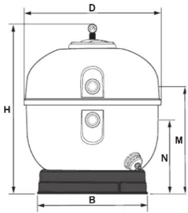
2.4.2 Dimensions
| SFSM60 | SFSM100 | SFSM100F | SFSM120 | SFSM120F | SFSM140 | SFSM140F | |
| Dim “H” | 34"(86.3 cm) | 41"(104.1 cm) | 41"(104.1 cm) | 47"(119.4 cm) | 47"(119.4 cm) | 49.7"(126.2 cm) | 49.7"(126.2 cm) |
| Dim “D” | 26.0"(66.0 cm) | 32.5"(82.6 cm) | 32.5"(82.6 cm) | 35.5"(90.2 cm) | 35.5"(90.2 cm) | 37.5"(95.3 cm) | 37.5"(95.3 cm) |
| Dim “N” | 13.625"(34.6 cm) | 16.5"(41.9 cm) | 16.05"(40.7 cm) | 18.75"(47.3 cm) | 18.6"(47 cm) | 18.75"(47.26 cm) | 18.6"(47 cm) |
| Dim “M” | 21.12"(53.6 cm) | 24"(61 cm) | 23.77"(60.3 cm) | 26.41"(67 cm) | 26.41"(67 cm) | 26.41"(67 cm) | 26.41"(67 cm) |
| Dim “B” | 19.29"(49 cm) | 24.6"(62.5 cm) | 24.6"(62.5 cm) | 27.75"(70.5 cm) | 27.75"(70.5 cm) | 27.75"(70.5 cm) | 27.75"(70.5 cm) |
| Weight(empty) | 70 lbs(31.8 kg) | 75 lbs(34.0 kg) | 80 lbs(36.3 kg) | 143 lbs(65 kg) | 147 lbs(67 kg) | 147 lbs(67 kg) | 150 lbs(68 kg) |
Figure 1. Filter Dimensions
2.5 Function
Jandy high rate sand filters pass unfiltered (dirty) water through sand or sand over a shallow layer of pea gravel. Water enters the filter at the inlet. Unfiltered water then passes through the diffuser(s) and moves down through the filter medium. Larger particles are deposited at the sand bed surface and finer particles are captured in the spaces between the sand grains. Filtered (clean) water then returns to the pool through the laterals.
Over time dirt and particles collected in the filter will make it more difficult for water to pass through, causing a rise in the operating pressure of the filter. When this occurs it will be necessary to perform a backwash procedure.
Remember to fill the filter halfway with water before loading the filter media.
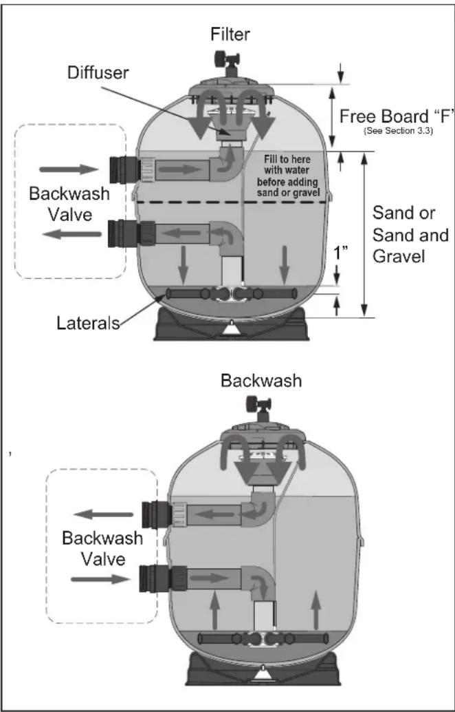
Figure 2. Filter and Backwash Function
During a backwash, water is routed into the outlet port from the filter pump. The water then moves up through the filter media stirring and dislodging particles and debris. The backwashed water is forced back through the diffusers and out the inlet port which will be routed to waste drainage.

WARNING
Use equipment only in a pool or spa installation. Do not connect system to an unregulated city water system or other external source of pressurized water producing pressures greater than 35 PSI.
2.6 Equipment Location
All pool water recirculation system components need to be installed in accordance with the standards and instructions in effect in your county or municipality. Utmost care must be taken to ensure that the equipment is located such that it is able to be safely operated and maintained.
2.6.1 Equipment Pad
The filter along with the other primary components of your pool water recirculation system should be installed on a level, prepared footing, which is capable of supporting the weight of the filter and which will accommodate the use of anchoring bolts to secure the equipment in place. Check local building codes for any additional requirements. If possible the equipment pad area should be:
- Dry.
- Well ventilated.
- Supplied with sufficient drainage.
• Out of direct sunlight. - Located away from eaves or overhangs where rain gutters are not installed.
- Away from overhanging trees or other foliage that may produce waste or debris of any kind that could clog, block or otherwise disrupt the regular operation and maintenance of the equipment.
- As close to the primary body of water as possible. Additional pipe length reduces efficiency due to pipe friction.
2.6.2 Filter Location
The filter must be installed on a firm, solid, non-absorbent level surface; and per the requirements of local codes and Authority Having Jurisdiction (AHJ). Filter systems can weigh up to 1,100 lbs. Use suitably rated mounting surface materials to avoid risk of settlement, and never use sand to level the filter as the sand will wash away. Check local building codes for additional requirements. On the equipment pad, the filter should be positioned so that it is:
- At least 6 inches away from walls and/or landscaping to allow for servicing.
- Not located below any eyes, overhangs, coverings or landscaping that might prevent or impede the removal of the filter lid and/or the proper servicing or replacement of the internal components.
- At least 5 feet away from any electrical controls or inputs.
-
In line, as best as possible, with other equipment in order to minimize turns in plumbing which can result in diminished efficiency.
-
Able to safely direct water drainage.
- Accessible for drainage and proper sand removal.
- Able to purge air and water safely away from other equipment, electrical controls or connections.
• Stationary and not subject to movement.
If the filter needs to be located above the water level of the pool, it can be raised 2.5 ft. without affecting the pump efficiency. A check valve is recommended on the suction line to the pump.
If the filter is to be installed below the water level of the pool, isolation valves should be installed on both the suction and return lines to prevent back flow of pool water during any routine servicing that may be required.
WARNING
Water discharged from an improperly positioned filter or valve can create an electrical hazard which can cause death, serious injury or property damage.
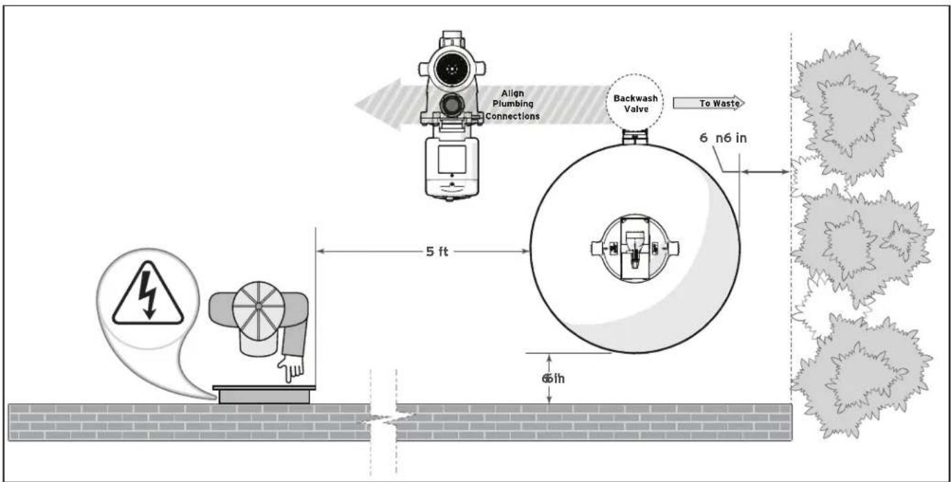
Figure 3. Filter Location Requirements
2.6.3 Anchoring the Filter to the Equipment Pad
In some areas, building codes require that all appliances be securely fastened to the equipment pad in order to withstand high wind pressures created by hurricanes. Please follow all local codes and standards. Anchor screws and washers are not included with the filter.
- After placing the filter, drill a hole at each of the three (3) holes in the base of the filter. (The correct size concrete drill bit should be obtained when the concrete screws are purchased.) The concrete screws must meet any and all applicable building code requirements.
- Install the screws and washers to secure the filter to the equipment pad. See Figure 4. Do not over torque the screws.
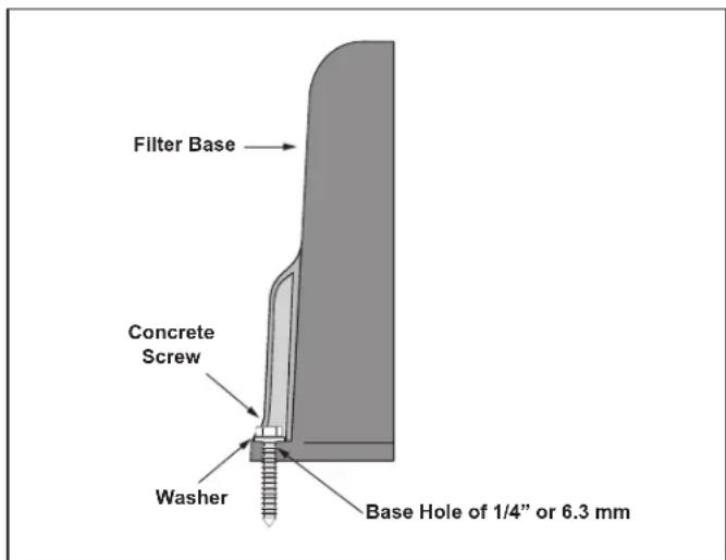
Figure 4. Install Anchor Screws
Section 3. Setup
3.1 Install Pressure Gauge
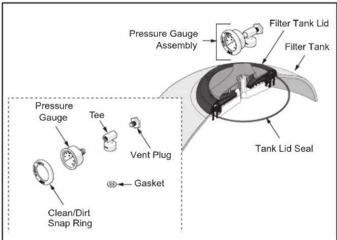
The pressure gauge is located in the accessory bag. Mount the pressure gauge/air release valve assembly, to the lid of the filter tank:
- Place the gasket inside the bottom connection of the tee.
- Thread the tee onto the threaded stem of the of the lid assembly.
- It is not necessary to use PTFE tape.
- Thread the vent plug into the larger corner hole of the tee.
- Wrap the threads of the pressure gauge with PTFE tape and thread into the tee until water tight. Make sure the gauge is oriented properly. Do not over tighten the pressure gauge. Over tightening may cause the tee to crack.
- Place the snap ring on the gauge after the filter is installed and the pump is running. Align the "Clean" arrow with the pressure reading and press the ring over the pressure gauge. If adjustments need to be made, hold the pressure gauge with one hand while rotating the ring with the other in order to prevent the gauge from rotating. Over rotation in either direction may cause leaks or crack the tee fitting.
flowchart
graph TD
    A["Pressure Gauge Assembly"] --> B["Filter Tank Lid"]
    B --> C["Filter Tank"]
    D["Tank Lid Seal"] --> E["Gasket"]
    F["Tee"] --> G["Vent Plug"]
    H["Clean/Dirt Snap Ring"] --> I["Pressure Gauge"]
Figure 5. Lid and Pressure Gauge Installation
CAUTION
Maintain your pressure gauge in good working order. The pressure gauge is the primary indicator of how the filter is operating.
3.2 Plumbing
WARNING
To avoid an electrical shock hazard, which can result in serious injury or death, ensure that all electrical power to the system is turned off before approaching, inspecting or troubleshooting any leaking valves or plumbing that may have caused other electrical devices in the surrounding area to get wet.
This filter operates under pressure. Install only on the discharge side of a pump system.
When the lid is installed properly and the filter is operated without air in the water system, this filter will operate in a safe manner.
If the system can be subjected to a higher pressure than the maximum pressure rating of any component, install an ASME ^® compliant automatic pressure relief valve or pressure regulator in the circulation system. Set the relief valve or pressure regulator to lowest working pressure of any of the components in the system.
DO NOT INSTALL a positive shutoff valve on the outlet plumbing of the filter. If the pump is operated with a closed valve at the outlet, an explosive condition could result. Sometimes equipment isolation valves are required for installations where the filter and other equipment are below the pool water level. Check valves should be used to allow for equipment maintenance without draining down the pool. If the application calls for positive or manual shutoff valves, any shutoff valves are to be prominently labeled "WARNING: Explosive Hazard. Do Not Run System With Valve Closed."
In addition, the use of isolation valves could cause a no flow condition at other equipment. Running any equipment with no flow could seriously damage the equipment.
Chemical feeders and/or chlorine generators should be installed downstream of both the filter and the heater and a check valve should be installed to prevent treated water from back flowing from the chlorine generators or chemical feeders.
CAUTION
Operating at high vacuum levels can cause the tank vessel to crack and leak with the potential for property damage.
Backwash (waste) piping that discharges water at an elevation of 10 ft. or lower than the water surface of the pool should be equipped with a vacuum-breaker in the waste piping within 10 ft. in vertical drop from the elevation of the pool surface.
3.2.1 Plumbing Connections
- Place the filter on the concrete pad, lined up with the inlet/outlet pipes. See Figure 3.
- To reduce the loss of pressure, it is recommended to use a pipe equal to or greater than the diameter of the outlets, for the installation of the system.
-
Install the backwash valve.
-
Connect the inlet and outlet plumbing to the valve as detailed in the valve manual.
- For best efficiency use the fewest possible number of fittings. This will prevent a restriction in the water flow.
- Make all plumbing connections in accordance with local plumbing and building codes.
- Filter connections are provided with an o-ring seal. To avoid damage to the O-Rings, use only a silicone base lubricant on the O-Rings.
- DO NOT USE pipe joint compound, glue or solvent on union coupling nuts.
- Do not use Teflon® tape or pipe dope on any unions.
- Keep piping tight and free of leaks. Pump suction line leaks may cause air to be entrapped in filter tank or loss of prime at the pump.
- Support the inlet/outlet pipes independently to prevent any undue strains on the backwash valve.
3.3 Fill the Filter
Jandy high rate sand filters most commonly use sand as a filter medium, or sand over a shallow layer of pea gravel. See Figure 2. The use of filter media other than sand is also described in Setup section, Alternative Filter Media.
-
Sand density can vary depending on the sand and how much moisture it is carrying. For this reason, consider the sand weights given in Table 1 as approximation only. The free board distance is the most important variable and should be maintained.
-
If pea gravel is used, it will cover the laterals to approximately 1" above the laterals. See Figure 2.
- All media to be marked as meeting NSF® requirements for sand filters.
- Sand is to be #20 Silica Sand (.016"-.021").
- Pea gravel, if used, is to be 1/8" to 1/4" diameter range.
-
Before adding any filter media, ensure the laterals (spokes) are screwed firmly into the hub and that the hub is centered in the tank with the laterals (spokes) horizontal. Check for any broken laterals (spokes) which may have been accidentally damaged by rough handling during shipment. Replace any broken parts if necessary.
-
Fill the filter halfway with water before loading the filter media. See Figure 2.
-
Cover each of the diffusers with a plastic bag.
-
Care must be taken so that filter media does not get into the diffusers.
- Take care not to dislodge the vent tubing and vent screen. See Figure 7.
CAUTION
To avoid damaging the laterals (spokes), slowly add the filter media until the laterals are fully covered. Cracked or broken laterals (spokes) will cause sand to be discharged to the pool.
WARNING
The automatic vent screen and tubing must be positioned properly to avoid trapping air inside the filter. Trapped air can cause product failure or also cause the filter lid to be blown off, which can result in death, serious personal injury, or property damage.
- Use a small scoop and pour pea gravel SLOWLY into the filter.
- Level the surface of the gravel, 1" above laterals.
- Use a small scoop and pour in the appropriate amount of sand according to the level indicated in Table 1.
- If using sand only, use a small scoop and pour it into the filter SLOWLY to the level indicated in Table 1.
- Remove and coverings from the diffusers.
- Check to ensure the vent tubing is appropriately positioned in the tank. See Figure 6.
- Using water only, rinse away any sand or dirt particles in the threads in the top of the tank.
- Ensure diffuser(s) are upright and centered properly.
- Make sure that the automatic vent tubing is in place (threaded through the diffuser) and the vent screen is installed at the top of the vent tubing. See Figure 7.
Table 1. Required Sand Level
| Model | Freeboard "F" (Manual to NSF) | Sand Only | Layered Media | |
| Sand Pea Gravel | ||||
| SFSM60 | 12.4"31.5 cm | 375 lbs170.1 kg | 300 lbs136.1 kg | 75 lbs34.0 kg |
| SFSM100SFSM100F | 15.0"38.1 cm | 625 lbs283.5 kg | 500 lbs226.8 kg | 150 lbs68.0 kg |
| SFSM120SFSM120F | 13.5"34.3 cm | 1050 lbs476.3 kg | 875 lbs396.9 kg | 200 lbs90.7 kg |
| SFSM140SFSM140F | 16.0"40.6 cm | 1200 lbs544.3 kg | 1075 lbs487.6 kg | 200 lbs90.7 kg |
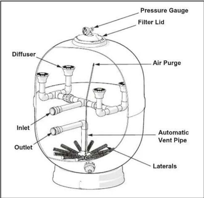
Figure 6. Automatic Air Relief
3.3.1 Alternative Filter Media
Jandy SFSM filters are designed to work with any NSF approved filtration media as an alternative to sand. Please follow the media manufacturer's recommendations for application instructions as well as Jandy's guidance on freeboard level requirements (see Table 1, Required Sand Level). Jandy's guidance on freeboard level should always be followed.
3.4 Install The Filter Lid
CAUTION
Ensure that the o-ring is completely clean and lubricated with a non-petroleum based lubricant. Before subjecting the filter to pressure, ensure that the handle is revolved as tightly as possible so that a good seal is achieved. See Figure 5.
WARNING
Follow these instructions carefully. Improper lid installation can cause product failure or also cause the filter lid to be blown off, which can result in death, serious injury, or property damage.
WARNING
Never attempt to adjust or remove the lid when the pump is running or there is pressure in the system. This can cause product failure or also cause the filter lid to be blown off which can result in death, serious personal injury, or property damage.
WARNING
Inspect the lid and tank for any damage before installing the lid. A damaged lid or tank could cause the lid to be blown off which can result in death, serious personal injury, or property damage.
3.4.1 Removing Filter Lid
- Turn the hand wheel (A) in a counterclockwise direction until it becomes loose. See Figure 7.
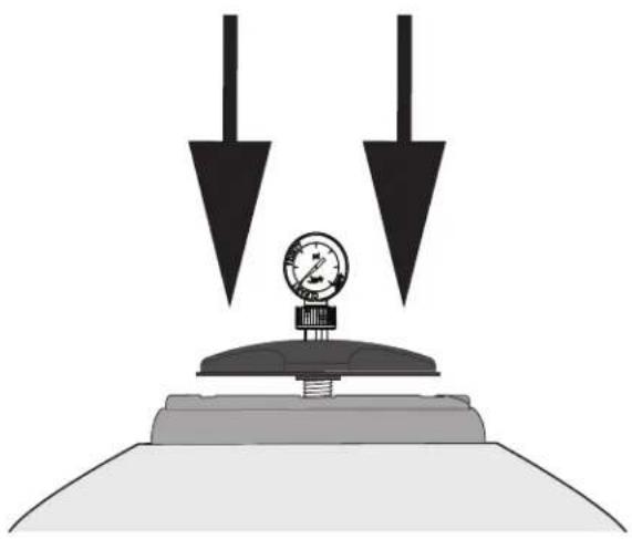
- Press down on the hand wheel firmly to release the O-Ring. See Figure 8
- Before removing the lid, turn it 15^ in a counterclockwise direction (B) See Figure 7. Lift the whole lid by the hand wheel.
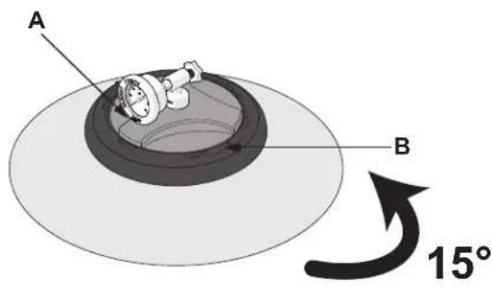
Figure 7. Loosen Hand Wheel
natural_image
Diagram of a pressure gauge mounted on a base with two downward arrows indicating downward pressure, no text or symbols present.Figure 8. Tap to Release O-Ring
3.4.2 Replacing Filter Lid
- Start with the lid completely off the filter to ensure the O-Ring is uncompressed. Fig 9
- Insert the lid into the filter until it drops home. Turn the lid 15^ clockwise (A), then turn the hand wheel (B) as far as it will go clockwise. Fig. 10
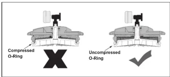
Figure 9. Ensure O-Ring is Uncompressed
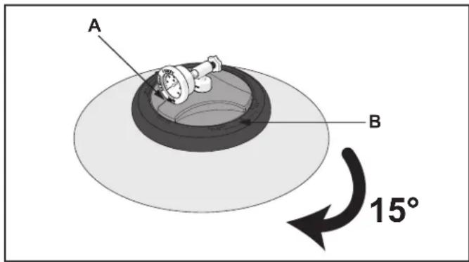
Figure 10. Tighten Lid (A) Then Hand Wheel (B)
Section 4. Startup And Operation
4.1 Startup
This section applies to new pools and seasonal start ups.
WARNING
NEVER attempt to assemble, disassemble or adjust the filter when there is pressurized air in the system. Starting the pump while there is any pressurized air in the system can cause product failure or also cause the filter lid to be blown off, which can cause death, serious personal injury or property damage.
WARNING
NEVER start pump while standing within 5 feet of the filter. Starting the pump while there is pressurized air in the system can cause product failure or also cause the filter lid to be blown off, which can cause death, serious personal injury or property damage.
- Make sure pool is cleaned before filling with water to avoid component damage from excessive debris and dirt particles.
- If the pool is new concrete, gunite or has a lot of debris or plaster dust which may be difficult to remove; it is recommended that the filter be run in filtration “FILTER” mode for 48 hours before performing the backwash procedure described below.
- Turn off the pump at the circuit breaker.
- Check that the drain plug is in place and tight.
- Check that the lid is correctly seated and tight. See Figure 5.
- Ensure the pressure gauge/release valve assembly is fully installed in the lid.
- Ensure the backwash piping is open.
-
Set backwash valve to the "Backwash" position.
-
If a multiport valve is used, set handle to the "Backwash" position indicated on the dial.
- If a slide valve is used, push the handle down to the backwash position and turn the handle to lock it in place.
-
For details please review the manufacturers instruction manual for your backwash valve.
-
Restore power to the pump at the breaker.
-
If the pump does not immediately prime, the following steps can be taken to achieve prime.
-
If necessary open the pump basket lid.
- Fill the pump basket with water to prime the system.
- Replace the lid. (You may have to do this several times on new and seasonal start-ups.)
- If the pump is located below the water level of the pool, you can open the filter pressure release valve to prime the pump with water.
- If the pump is located above the water level, remove the lid and fill the basket with water before starting the pump.
-
Prior to replacing the pump lid, check for debris around the lid O-Ring seat. Debris around the lid O-Ring seat will cause air to leak into the system, and make it difficult to prime the pump.
-
Hand-tighten the lid to make an air tight seal.
- Do not use any tools to tighten the lid.
- Ensure that the lid is secure.
- Ensure that all isolation valves are open.
-
Ensure that the unions are tight.
-
Open the air release valve by turning the thumbscrew on the back of the pressure gauge housing counterclockwise.
- Do not remove the thumbscrew. See Figure 5.
- Stand clear of the filter and turn the filter pump on.
- Once the filter pump is primed and begins filling the filter. The vent hole on the pressure gauge will expel air.
- If the vent hole does not expel air, turn off the filter pump.
- Double check that all isolation valves are open.
- Check to ensure that the filter pump has successfully primed and is filling the filter with water.
- Double check that the release valve thumbscrew has been loosened
- Air venting is complete when a steady stream of water is being produced at the vent hole.
- You should also see a steady flow of water being discharged from the "waste" drain line.
- Close the air release valve by turning the thumbscrew on the back of the pressure gauge housing clockwise until the flow of water from the vent hole stops.
- Run the filter using the backwash setting on your backwash valve for at least 3 to 5 minutes or until water runs clear.
4.2 Operation
This filter operates with a variety of backwash valves. The operational procedures described below attempt to cover use of the most common backwash valves. However, it is always recommended that you consult the manual for the backwash valve you are using on the filter.
CAUTION
To prevent the possibility of personal injury and equipment damage, always turn the pump off before changing the position of a backwash valve.
WARNING
NEVER operate the filter system at more than 50 psi of pressure. Operating filter system in excess of 50 psi can cause product failure or also cause the filter lid to be blown off, which can cause death, serious personal injury or property damage.
WARNING
DO NOT operate filter at water temperatures above 104^ F ( 40^ C). Water temperatures above the manufacturer's recommendations will shorten the life span of the filter and may void the warranty.
Always turn off the filter pump any time you are making adjustments to the backwash valve.
- Continue the initial backwash until the backwash water is clear (3 to 5 minutes).
- See Step 1 in Startup and Operation section, Startup if the pool is new or contains significant hard to remove particulates such as plaster dust.
-
Turn the pump off.
-
If you are using a multiport backwash valve that has a "Rinse" position do the following:
-
Set the selector handle to the "Rinse" position.
- Start the pump.
- Run for 30 to 40 seconds. This helps settle the sand bed and removes fine particles.
-
Turn the pump off.
-
Set backwash valve to normal operation position.
-
If a multiport valve is used, set handle to the "Filter" position Indicated on the dial.
- If a slide valve is used, pull the handle up to the filter position and turn the handle to lock it in place.
-
Make certain all inlet and return lines to the pool are open to allow free movement of water.
-
Open the air release valve by turning the thumbscrew on the back of the pressure gauge housing counterclockwise. Do not remove the thumbscrew. See Figure 5.
- Follow steps 10-14 from Startup and Operation section, Startup.
- After the pressure gauge has stabilized, turn the gauge ring so that the arrow next to the word "clean" aligns with the needle of the gauge.
- Record this initial “CLEAN” pressure. This reference will be necessary in the future.
- As the filter cleans the water and the sand begins to clog, the pressure will increase.
- The ring indicates an increased pressure of between 10 and 12 psi above original starting pressure.
- When the needle of the pressure gauge aligns with the arrow next to the word "dirty", it is time to clean the filter.
- Ensure pump speed remains the same when recording "CLEAN" and "DIRTY" pressure.
4.2.1 Filter Cleaning
After 48 hours of operation on a new pool, the filter should be backwashed to clear out plaster dust and debris from the pool construction. It is not recommended to backwash the filter on a timed basis, e.g. once a month. Pool, weather, dust conditions and pool occupancy all affect the frequency of the need to backwash.
Backwashing a filter too often will actually diminish the filter performance by limiting its ability to catch finer particles. Do not run your system 24 hours a day, day after day. Allowing the filter to stop periodically will allow slight disturbance of the “mud-deck” at the surface of the sand bed. This will lower the running pressure slightly after rest.
Backwashing your filter is required when the pressure gauge reading shows an increase of 10 to 12 psi above the “CLEAN” filter pressure. Another indicator of the need to backwash is when the flow back to the pool is reduced by 30% compared to the clean filter flow amount.
- Turn the pump off.
-
Ensure suction piping and backwash piping is open to ensure unobstructed flow through the filter and backwash line.
-
Set the backwash valve to the "Backwash" position.
-
If a multiport valve is used, set handle to the "Backwash" position indicated on the dial.
-
If a slide valve is used, push the handle down to the backwash position and turn the handle to lock it in place.
-
Stand clear of the filter and start the pump.
-
Backwash the filter for 3 to 5 minutes or until water runs clear.
- Turn the pump off.
-
If the multiport valve has a "Rinse" position do the following:
-
Set the selector handle in "Rinse" position.
- Run for one minute. This helps settle the sand bed.
-
Stop the pump.
-
Set backwash valve to normal operation position.
-
If a multiport valve is used, set handle to the "Filter" position Indicated on the dial.
- If a slide valve is used, pull the handle up to the filter position and turn the handle to lock it in place.
- Make certain all inlet and return lines to the pool are open to allow free movement of water.
-
Open the air release valve by turning the thumbscrew on the back of the pressure gauge housing counterclockwise. Do not remove the thumbscrew. See Figure 5.
-
Follow steps 10-14 from Startup and Operation section, Startup.
-
Align the gauge ring according to Step 6 from Startup and Operation section, Operation.
- If the pressure gauge after the backwash procedure indicates more than 5 psi difference above that reading, it will be necessary to chemically clean the sand bed. See next section.
4.2.2 Chemical Cleaning Procedure
Sand filter chemical cleaners remove oils, deposits and rust from the sand bed with a 12 hour overnight soaking when used according to the following instruction. Follow these instructions carefully. Do not allow the cleaning solution to be pumped back into the pool.
- Use an approved cleaner for sand filters.
- Approved cleaners should be available through your pool chemical retail store, or pool maintenance service or supplier.
-
If necessary, mix the proper solution per the manufacturer's label instructions.
-
Perform the backwash procedure as described in Filter Cleaning section.
-
Shut the pump off.
-
If the filter is installed below the pool water level, close the appropriate isolation valve(s) to prevent the pool from draining.
-
Drain the water from the filter. (See next section.)
-
After filter has drained, replace cap on drain fitting.
-
Place the backwash valve in "Backwash" position.
• Make certain backwash lines are open.
- Introduce cleaner to the water system.
- Follow all appropriate use and safety instructions from the filter cleaner manufacturer.
-
Follow steps 9-13 from Startup and Operation section, Startup, to fill the filter tank.
-
Turn off the pump.
-
Leave the filter valve in the "Backwash" position.
- Use caution not to introduce cleaning solution in the main body of pool water.
-
Disconnect the power at the breaker.
-
Allow the filter to stand for 12 hours.
-
After 12 hour soak, turn on the power breaker and follow instructions in Filter Cleaning section.
After chemical cleaning, your filter should return very close to the original "Clean" pressure reading on the filter pressure gauge that was noted at the time of the original installation with fresh sand. If not, note this
new "Clean" pressure reading for future reference.
Turn the ring on the filter gauge assembly so that the arrow next to the word "Clean" is aligned with the needle.
4.3 Draining the Filter and Removing the Filter Sand
For maintenance or repair it may be necessary to drain water from the filter or completely remove all the sand from the filter. The filter drain will allow for both water removal and the flushing of sand.
Any additional piping installed at the water drain must be removable in order to facilitate the further removal of drain components. Allow sufficient space for the flushing of sand from the filter. See Figure 11.
CAUTION
Be sure that all provisions for wastewater disposal meet local, state or national codes. During any backwashing or draining process, 100 gallons or more of pool water will be discharged. Do not discharge water where it will cause flooding or damage.
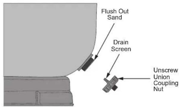
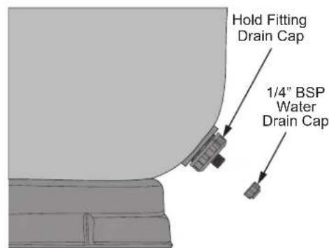
Figure 11. Drain Valve
4.3.1 Drain The Filter
-
Shut the pump off.
-
If the filter is installed below the pool water level, close the appropriate isolation valve(s) to prevent the pool from draining.
-
Loosen and remove the drain cap.
- Use caution not to misplace the drain plug.
-
Allow the filter to drain out as much water as needed.
-
Replace the plug and cap.
4.3.2 Remove the Filter Sand
-
Follow the draining procedure described in the Drain the Filter section.
-
Remove the filter lid.
- Before attempting to loosen or remove the lid, turn OFF the pump and OPEN the air release valve on top of the filter.
- DO NOT attempt to loosen or remove the lid while the pump is running or if the filter pressure gauge indicates there is pressure in the filter.
- First, try to remove the lid by hand using the handles.
- If removal by hand is not successful, use a mallet or soft-faced hammer to alternately strike the handles to loosen the lid.
- Use caution not to damage the lid O-Ring or the pressure gauge assembly.
-
Using a scoop reach into the filter and remove as much sand as possible.
-
Use caution not to get sand into the diffusers.
-
The diffusers can be covered with a plastic bag to help avoid sand intrusion.
-
If available use a wet/dry vacuum to remove as much of the remaining sand as possible.
-
Loosen and remove the universal coupling nut.
-
Carefully draw out the drain screen.
-
Use caution not to misplace the O-Ring.
-
Use water to flush remaining filter media from the filter tank.
- The larger tank drain is a universal union fitting. Sand removal is easiest without further restriction at this fitting. However, if a short piece of piping is desired to direct the sand being flushed away from the filter base, a universal tailpiece and union nut can be used. See Figure 11.
Section 5. Maintenance
5.1 General Maintenance
- The outside of the filter can be cleaned with a mild detergent and water. Rinse with water.
- Do not use strong cleansers or solvents to clean the filter, solvents will damage the plastic components of the filter.
- Check pressure during operation at least once a week.
- Check for and remove any debris from the skimmer basket and strainer basket on pump regularly.
- Check pump and filter for any leaks. If any leaks develop, turn off the pump and call a qualified pool service technician.
- Product safety signs or labels should be periodically inspected and cleaned by the product user as necessary to maintain good legibility from a safe viewing distance.
- Product safety signs or labels should be replaced by the product user when a person with normal vision, including corrected vision, is no longer able to read the safety signs or label message panel text at a safe viewing distance from the hazard.
- In cases where the product has an extensive expected life or is exposed to extreme conditions, the product user should contact either the product manufacturer or some other source to determine means for obtaining replacement signs or labels.
- Installation of new replacement safety signs or labels should be in accordance with the sign or label manufacturer's recommended procedure.
5.2 Pressure Gauge
- During operation of the filtration system, check the pressure gauge/air release assembly for air or water leaks at least once a week.
- Keep the pressure gauge in good working order. If you suspect a problem with the gauge, Jandy® recommends you call a qualified service technician to do any work on the filter/pump system.
5.3 Winterizing
- Backwash the filter. See Filter Cleaning section.
- Turn OFF the pump at the circuit breakers.
- Open the air release valve on top of the filter.
- Remove the drain cap at the base of the filter to ensure that the tank is empty. Store the drain cap and seal in a safe place. Do not reinstall until next season at start-up.
- Drain system piping of all water.
- If using a multiport backwash valve that has a “Winterize” position, move selector lever to that position. The “Winterize” position which leaves all ports partially open, and on some backwash valves also moves the seal to a relaxed position.
- Cover the system with a tarpaulin or plastic sheet to protect it from the weather. Do not wrap electrical motors in plastic.
Section 6. Troubleshooting
- For a list of common problems and solutions see the Troubleshooting Guide.
- Jandy recommends that you call a qualified service technician to do any work on the filter/pump system.
- To locate a service company near you, please visit Jandy.com. For technical support, please call 800-822-7933 or email productsupport@Jandy.com.
Section 7. Performance
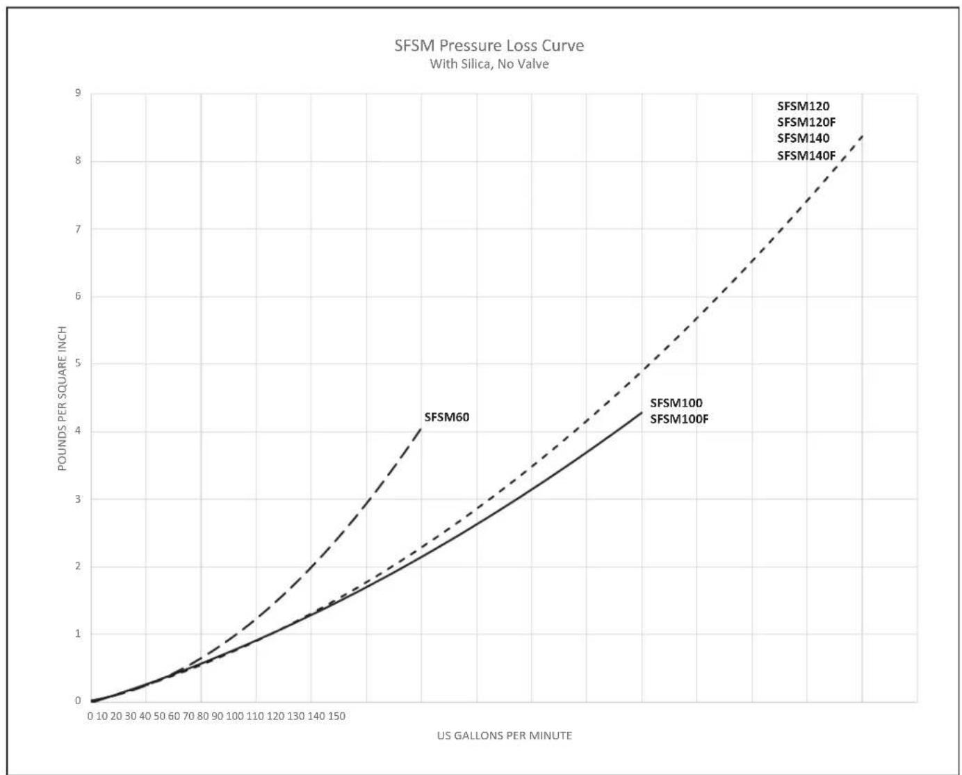
Table 2. Jandy SFSM Series Filters Pressure Loss Curve
line
| US Gallons Per Minute | SFSM60 | SFSM100 | SFSM120 | SFSM120F | SFSM140 | SFSM140F | | --------------------- | ------ | ------- | ------- | -------- | ------- | -------- | | 0 | 0.0 | 0.0 | 0.0 | 0.0 | 0.0 | 0.0 | | 70 | 0.5 | 0.5 | 0.5 | 0.5 | 0.5 | 0.5 | | 140 | 1.5 | 1.5 | 1.5 | 1.5 | 1.5 | 1.5 | | 150 | 4.0 | 4.0 | 4.0 | 4.0 | 4.0 | 4.0 |Section 8. Product Specifications and Technical Data
For a complete list of replacement parts, please visit www.Jandy.com or contact Technical Support at 1.800.822.7933 or email productsupport@fluidra.com
In Canada, please call 1.888.647.4004 or email service.canada@fluidra.com
8.1 Exploded Views
- Lid Assembly
- Gauge and Air Release Assembly
- Pressure Gauge
- Lock Ring with Hardware
- Filter Base
- Inlet Plumbing
- Diffuser
- Breather Tube Assembly
- Outlet Plumbing
- Laterals
- Bulkhead Fitting with O-Rings and Unions
- Drain Cap
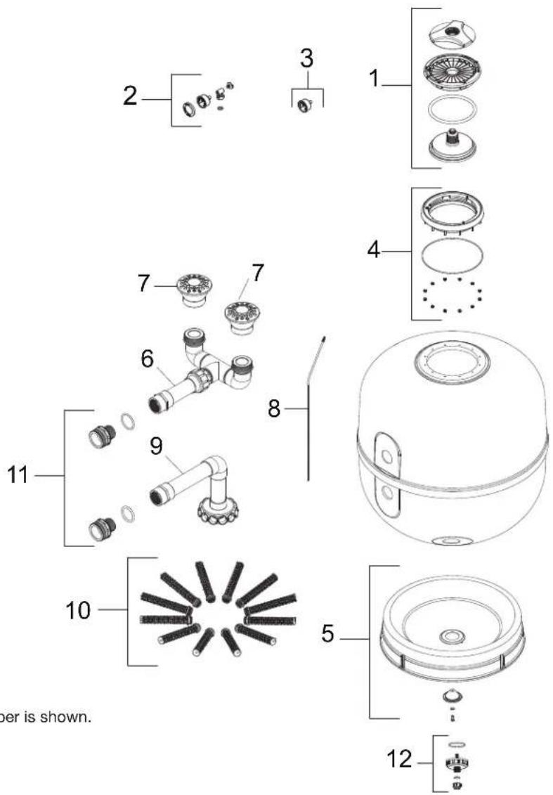
NOTE: SFSM100 model number is shown.
Figure 12. SFSM Filter Exploded View (Models may differ slightly from illustration)
Zodiac Pool Systems LLC
2882 Whiptail Loop # 100
Carlsbad, CA 92010, USA
Jandy.com | 1.800.822.7933
Zodiac Pool Systems Canada, Inc.
2-3365 Mainway
Burlington, ON L7M 1A6, Canada
Jandy.ca | 1.800.822.7933
A Fluidra Brand
©2022 Zodiac Pool Systems LLC. All rights reserved, ZODIAC ^® is a registered trademark of Zodiac International, S.A.S.U., used under license. All other trademarks are the property of their respective owners.
28342S4E200_REVD

natural_image
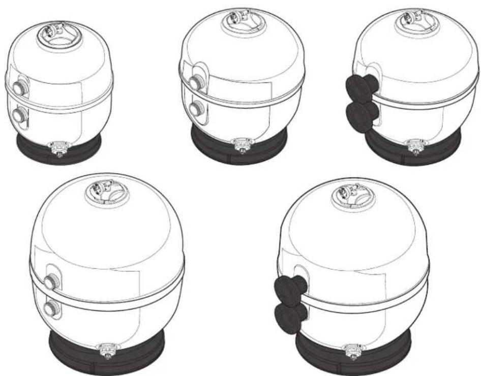
Five identical line drawings of a cylindrical industrial component with black bases and mounting holes, shown from different angles (no text or symbols)Filtre à sable
Modèles : SFSM60, SFSM100, SFSM120, SFSM140, SFSM100F, SFSM120F, SFSM140F
AVERTISSEMENT
Section 3. Configuration ......28
Section 7. Performance....38
natural_image
Simple icon of a pair of safety goggles inside a circle (no text or symbols)natural_image
Circular icon showing two gloves, one open and one closed, with no text or symbols.Gants
natural_image
Illustration of a pair of pliers inside a circular frame (no text or symbols)Pince multiprise
natural_image
Simple diagram with three icons inside a circle, no text or symbols presentNiveau
natural_image
Simple line drawing of a shovel inside a circle (no text or symbols)Pelle

natural_image
Simple icon of a bottle with a glass rod and a circular background (no text or symbols)Section 3. Configuration
natural_image
Diagram of a pressure gauge mounted on a base with two downward arrows indicating downward pressure, no text or symbols present.Section 7. Performance
Zodiac Pool Systems LLC
2882 Whiptail Loop # 100
Carlsbad, CA 92010, USA
Jandy.com | 1.800.822.7933
Zodiac Pool Systems Canada, Inc.
2-3365 Mainway
Burlington, ON L7M 1A6, Canada
Jandy.ca | 1.800.822.7933
Une marque Fluidra
natural_image
Simple icon of a pair of safety glasses inside a circle (no text or symbols)Gafas de seguridad
natural_image
Icon of two gloves inside a circle (no text or symbols)natural_image
Illustration of a pair of pliers inside a circular frame (no text or symbols)
natural_image
Simple diagram with three icons inside a circle (no text or labels)Nivel
natural_image
Simple line drawing of a shovel inside a circle (no text or symbols)Pala

natural_image
Simple icon of a bottle with a hammer and sphere inside a circle (no text or symbols)natural_image
Diagram of a pressure gauge mounted on a base with two downward arrows indicating downward pressure, no text or symbols present.Zodiac Pool Systems LLC
2882 Whiptail Loop # 100
Zodiac Pool Systems Canada, Inc.
2-3365 Mainway
Jandy.ca | 1.800.822.7933
- Table of Contents
- Section 1. Important Safety Instructions......3
- Section 2. Getting Started....4
- Section 3. Setup....8
- Section 4. Startup And Operation .... 12
- Section 5. Maintenance....16
- Section 6. Troubleshooting .... 17
- Section 7. Performance....18
- Section 8. Product Specifications and Technical Data ....19
- SAVE THESE INSTRUCTIONS
- EQUIPMENT INFORMATION RECORD
- Section 1. Important Safety Instructions
- READ AND FOLLOW ALL INSTRUCTIONS
- Safety Instructions
- WARNING
- MAXIMUM OPERATING PRESSURE OF THE FILTER IS 50 PSI.
- NEVER SUBJECT THE FILTER TO ANY OPERATING PRESSURE EXCEEDING 50 PSI.
- To avoid electrical shock hazard, which can result in serious injury or death:
- CAUTION
- Section 2. Getting Started
- Package Contents
- Jandy Valve ® Compatibility
- Required Tools/Equipment
- Specifications And Dimensions
- Specifications
- Dimensions
- Function
- Remember to fill the filter halfway with water before loading the filter media.
- Equipment Location
- Equipment Pad
- Filter Location
- Anchoring the Filter to the Equipment Pad
- Section 3. Setup
- Install Pressure Gauge
- Plumbing
- Plumbing Connections
- Fill the Filter
- Alternative Filter Media
- Install The Filter Lid
- Removing Filter Lid
- Replacing Filter Lid
- Section 4. Startup And Operation
- Startup
- Operation
- Filter Cleaning
- Chemical Cleaning Procedure
- Draining the Filter and Removing the Filter Sand
- Drain The Filter
- Remove the Filter Sand
- Section 5. Maintenance
- General Maintenance
- Pressure Gauge
- Winterizing
- Section 6. Troubleshooting
- Section 7. Performance
- Section 8. Product Specifications and Technical Data
- Exploded Views
- Filtre à sable
- AVERTISSEMENT
- Section 3. Configuration ......28
- Section 7. Performance....38
- Section 3. Configuration
Brand : Jandy
Model : SFSM-60
Category : Water filter