CBT60RBG-07 - Basket CANDY - Free user manual and instructions
Find the device manual for free CBT60RBG-07 CANDY in PDF.

| Product type | Cooker hood |
| Brand | Candy |
| Model | CBT60RBG-07 |
| Width | 60 cm |
| Height | 51.6 cm |
| Depth | 49.6 cm |
| Power supply | 220-240 V ~ 50 Hz |
| Installation type | Wall-mounted or under cabinet |
| Control type | Toggle switches |
| Speeds | 2 (low, high) |
| Lighting | 1 x LED 2 W max, 110-240 V~ |
| Grease filter | Aluminum mesh filter (2 pieces) |
| Charcoal filter | Optional, not supplied |
| Material | Stainless steel |
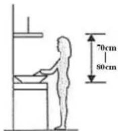
| Minimum distance gas hob | 75 cm |
| Minimum distance electric hob | 65 cm |
| Air outlet diameter | 150 mm (estimate) |
| Evacuation mode | Extraction or recirculation (with charcoal filter) |
| Maintenance | Regular cleaning of filters and surfaces |
| Safety | Disconnect before maintenance; do not use without filters |
Frequently Asked Questions - CBT60RBG-07 CANDY
User questions about CBT60RBG-07 CANDY
0 question about this device. Answer the ones you know or ask your own.
Ask a new question about this device
Download the instructions for your Basket in PDF format for free! Find your manual CBT60RBG-07 - CANDY and take your electronic device back in hand. On this page are published all the documents necessary for the use of your device. CBT60RBG-07 by CANDY.
USER MANUAL CBT60RBG-07 CANDY
natural_image
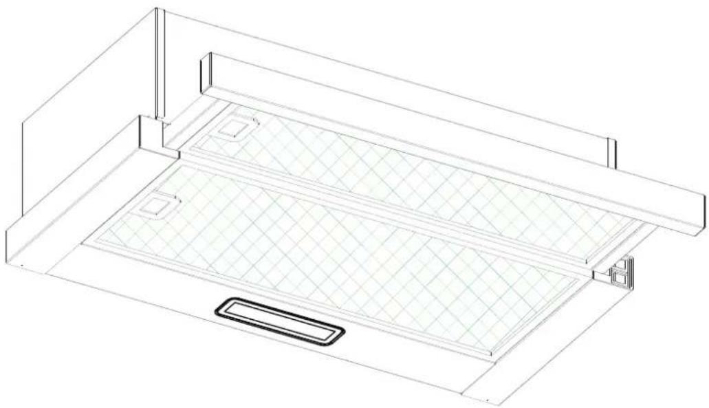
Isometric line drawing of a two-tiered storage unit with mesh pattern and control panel (no text or symbols)ENGLISH(EN)---- page 001
CZECH (CS)---- page 013
FRENCH (FR)---- page 025
POLISH (PL)---- page 038
SLOVAK (SK) -- page 051
SERBIAN (SR)---- page 064
ROMÂNĂ (RO)---- page 076
HRVATSKI (HR)---- page 088
Cooker Hood
Instruction Manual
natural_image
Isometric line drawing of a two-tiered storage unit with grid pattern and control panel (no text or symbols)Content
1....Safety instructions
2....Installation
3....Start using your cooker hood
4....Troubleshooting
5....Maintenance and cleaning
6 Environment protection
SAFETY INSTRUCTIONS
This manual explains the proper installation and use of your cooker hood, please read it carefully before using even if you are familiar with the product. The manual should be kept in a safe place for future reference.
Never to do:
- Do not try to use the cooker hood without the grease filters or if the filters are excessively greasy!
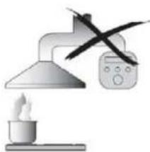
- Do not install above a cooker with a high level grill.
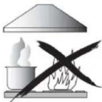
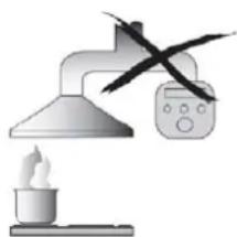
● Do not leave frying pans unattended during use because overheated fats or oils might catch fire.
● Never leave naked flames under the cooker hood.
natural_image
Illustration of a hot pot with steam rising and crossed by flames, no text or symbols present- If the cooker hood is damaged, do not attempt to use.
● Do not flambé under the cooker hood.
●CAUTION: Accessible parts may become hot when used with cooking appliances.
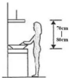
● The minimum distance between the supporting surface for the cooking vessels on the hob and the lowest part of the cooker hood. (When the cooker hood is located above a gas appliance, this distance shall be at least 65 cm)
● The air must not be discharged into a flue that is used for exhausting fumes from appliances burning gas or other fuels.
natural_image
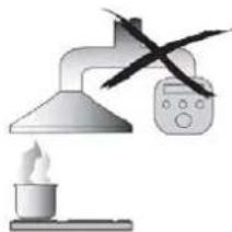
Illustration of a laboratory setup with a lamp, beaker, and control panel (no text or symbols)Always to do:
● Important! Always switch off the electricity supply at the mains during installation and maintenance such as light bulb replacement.
● The cooker hood must be installed in accordance with the installation instructions and all measurements followed.
● All installation work must be carried out by a competent person or qualified electrician.
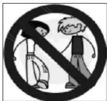
●Please dispose of the packing material carefully. Children are vulnerable to it.
● Pay attention to the sharp edges inside the cooker hood especially during installation and cleaning.
- When the cooker hood is located above a gas appliance, the minimum distance between the supporting surface for the cooking vessels on the hob and the lowest part of the cooker hood that distance must be:
Gas cookers: 75 cm
Electric cookers: 65 cm
Coal or oil cookers: 75 cm
● Make sure the ducting has no bends sharper than 90 degrees as this will reduce the efficiency of the cooker hood.
●Warning: Failure to install the screws or fixing device in accordance with these instructions may result in electrical hazards
Always to do:
● Always put lids on pots and pans when cooking on a gas cooker.
- When in extraction mode, air in the room is being removed by the cooker hood. Please make sure that proper ventilation measures are being observed. The cooker hood removes odours from room but not steam.
● Cooker hood is for domestic use only.
- If the supply cord is damaged, it must be replaced by the manufacturer, its service agent or similarly qualified persons in order to avoid a hazard.
● This appliance can be used by children aged from 8 years and above and persons with reduced physical, sensory or mental capabilities or lack of experience and knowledge if they have been given supervision or instruction concerning use of the appliance in a safe way and understand the hazards involved. Children shall not play with the appliance. Cleaning and user maintenance shall not be made by children without supervision.
● Warning: Before obtaining access to terminals, all supply circuits must be disconnected.
Always to do:
● Caution: The appliance and its accessible parts can become hot during operation. Be careful to avoid touching the heating elements. Children younger than 8 years old should stay away unless they are under permanent supervision.
● There shall be adequate ventilation of the room when the cooker hood is used at the same time as appliances burning gas or other fuels.
● There is a fire risk if cleaning is not carried out in accordance with the instructions
● Regulations concerning the discharge of air have to be fulfilled.
● Clean your appliance periodically by following the method given in the chapter MAINTENANCE.
● For safety reason, please use only the same size of fixing or mounting screw which are recommended in this instruction manual.
● Regarding the details about the method and frequency of cleaning, please refer to maintenance and cleaning section in the instruction manual.
●Cleaning and user maintenance shall not be made by children without supervision.
- When the cooker hood and appliances supplied with energy other than electricity are simultaneously in operation, the negative pressure in the room must not exceed 4 Pa (4 x 10⁻⁵ bar).
● WARNING: Danger of fire: do not store items on the cooking surfaces.
●A steam cleaner is not to be used.
● NEVER try to extinguish a fire with water, but switch off the appliance and then cover flame e.g. with a lid or a fire blanket.
INSTALLATION (VENT OUTSIDE)
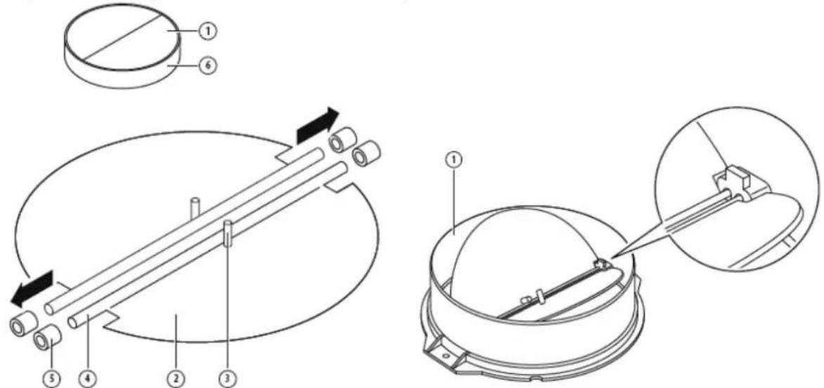
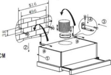
MOUNTING OF THE V-FLAP
*Optional accessory supplied only with some models.
If the cooker hood does not have an assembled V-flap 1, you should mount the half-parts to its body. The images only show an example of how to mount the V-flap, the outlet may be various according to different models and configuration.
To mount the V-flap 1 you should:
- Mount two half-parts 2 into the body 6
- a pin 3 should be top oriented;
- the axis 4 should be inserted in the holes 5 on body;
- repeat all the operations for the 2nd half-part
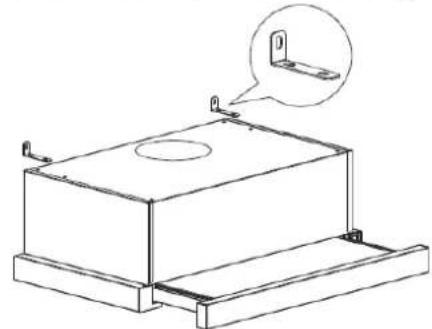
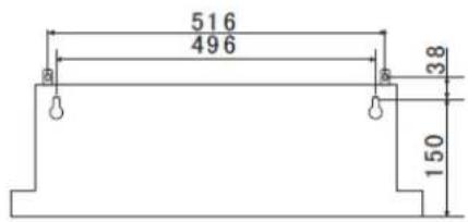
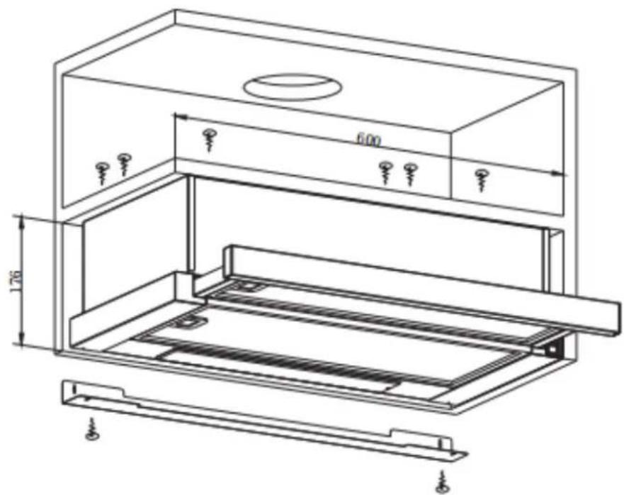
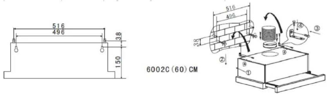
INSTALLATION (Wall Mounting)
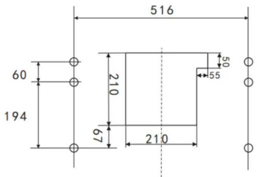
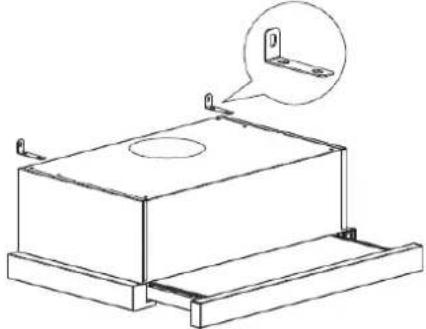
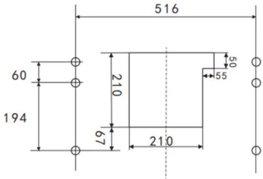
- Decide the location of the holes for fixing the cooker hood.
- Install the L-shaped bracket on the top of the hood by two screws (4mm x 10mm)
natural_image
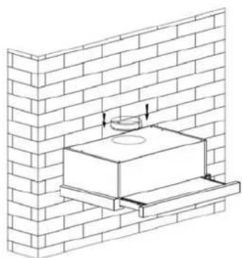
Technical line drawing of a rectangular enclosure with mounting brackets and a circular top opening, plus an inset showing a bracket detail (no text or symbols)- The cooker hood is wall mounted by 4 screws (4mm x 30mm) and wall plugs. Mount the cooker hood on the wall on the back of the cooker hood by 2 screws (4mm x 30mm) and wall plugs. Then fix the cooker hood on the wall by 2 screws (4mm x 30mm) and wall plugs through the small L-shaped bracket.
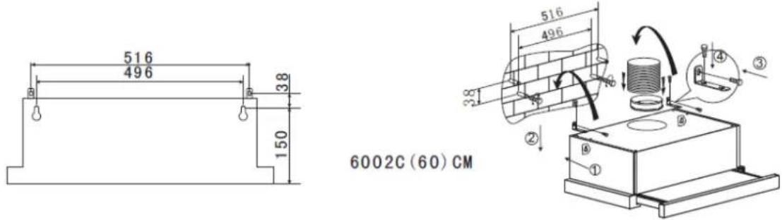
- Fix the one-way-valve to the air outlet of the cooker hood.
natural_image
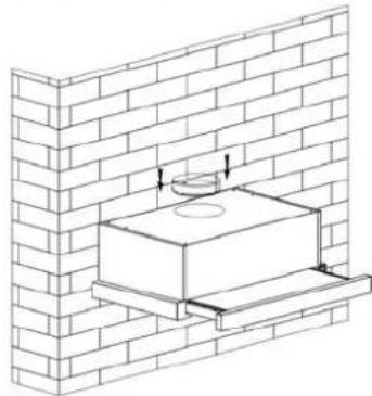
Technical line drawing of a brick wall with a rectangular base and a circular component, no text or symbols present.INSTALLATION (Cabinet Mounting)
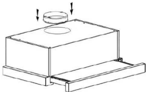
- Fix the one-way-valve to the air outlet of the cooker hood.
natural_image
Technical line drawing of a mechanical assembly with a cylindrical component and mounting base (no text or symbols)- Mount the cooker hood on the cabinet by 6 screws (4x35mm) and flat washers.
60CM
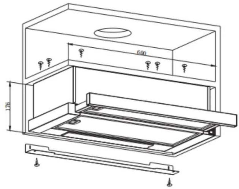
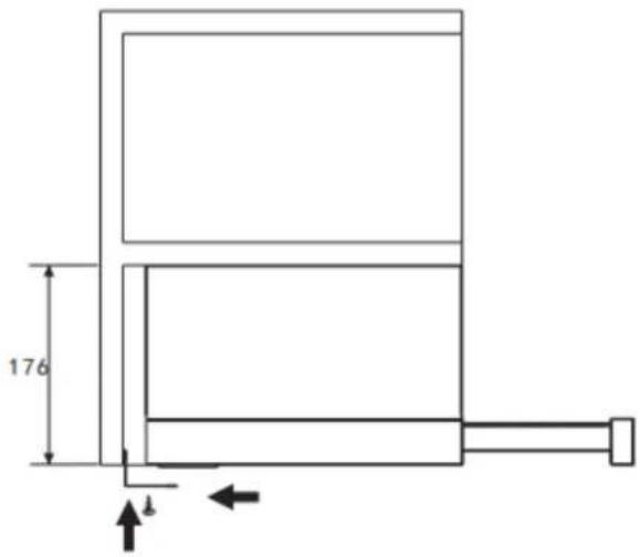
If there is gap between the wall and the cooker hood, you may install the L-shaped bracket on the bottom of the hood by two screws (3 x 12mm).
The installation of the L-shaped bracket is optional.
Note: The expansion pipe is not included in the product.
| WARNING: | ➢ For safety reason, please use only the same size of fixing or mounting screw which are recommended in this instruction manual.➢ Failure to install the screws or fixing device in accordance with these instructions may result in electrical hazards. |
 |
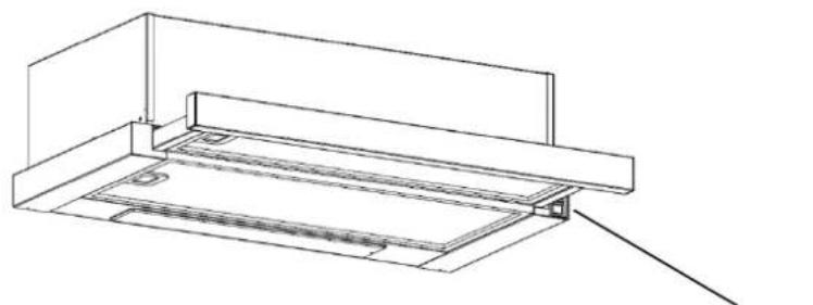
Start Using Your Cooker Hood
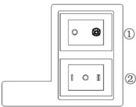
Rocker switch
natural_image
Technical line drawing of a mechanical assembly with no visible text or symbolsRocker switch
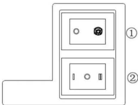
natural_image
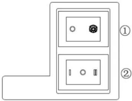
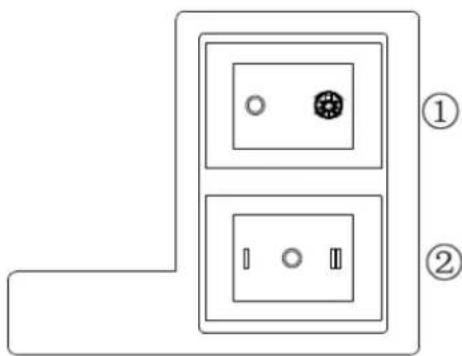
Diagram of two electrical outlets with circular and rectangular components, labeled ① and ② (no text or symbols on the diagram itself)- Insert the power plug into the socket.
- Push switch ① to , the lamp will be on; push switch ① to "0", the lamp will be off.
-
Push the switch ② into “I、II”, the motor will be on “low、high” two speeds, push into “0”, the motor will be off.
-
The power will be connected when pull out the front panel. Conversely, the power will be automatically disconnected.
TROUBLESHOOTING
| Fault | Possible Cause | Solution |
| Light on, but motor does not work | Fan switch turned off Select a fan switch position. | |
| Fan switch failed | Contact service center. | |
| Motor failed | Contact service center. | |
| Light does not work, motor does not work | House fuses blown Reset/Replace fuses. | |
| Power cord loose or disconnected | Refit cord to power outlet.Switch power outlet on. | |
| Oil leakage | One way valve and the outlet are not tightly sealed | Take down the one way valve and seal with sealant. |
| Leakage from the connection of chimney and cover | Take chimney down and seal. | |
| Lights not working | Broken/Faulty globes | Replace globes as per this instruction. |
| Insufficient suction | The distance between the cooker hood and the gas top is too far | Refit the cooker hood to the correct distance. |
| The Cooker hood inclines | The fixing screw not tight enough | Tighten the hanging screw and make it horizontal. |
NOTE:

Any electrical repairs to this appliance must conform to your local, state and federal laws. Please contact the service centre if in any doubt before
undertaking any of the above. Always disconnect the unit from the power source when opening the unit.
MAINTENANCE AND CLEANING
Caution:
- Before maintenance or cleaning is carried out, the cooker hood should be disconnected from the main power supply. Ensure that the cooker hood is switched off at the wall socket and the plug removed.
natural_image
Abstract line drawing of a stylized figure interacting with a wall and abstract shapes (no text or symbols)- External surfaces are susceptible to scratches and abrasions, so please follow the cleaning instructions to ensure the best possible result is achieved without damage.
GENERAL
Cleaning and maintenance should be carried out with the appliance cold especially when cleaning. Avoid leaving alkaline or acid substances (lemon juice, vinegar etc.) on the surfaces.
STAINLESS STEEL
The stainless steel must be cleaned regularly (e.g.weekly) to ensure long life expectancy.Dry with a clean soft cloth. A specialized stainless steel cleaning fluid may be used.
NOTE:
Ensure that wiping is done along with the grain of the stainless steel to prevent any unsightly crisscross scratching patterns from appearing.
CONTROL PANEL SURFACE
The inlay control panel can be cleaned using warm soapy water. Ensure the cloth is clean and well wrung before cleaning. Use a dry soft cloth to remove any excess moisture left after cleaning.
Important
Using neutral detergents and avoid using harsh cleaning chemicals, strong household detergents or products containing abrasives, as this will affect the appliance appearance and potentially remove any printing of artwork on the control panel and will void manufactures warrantee.
GREASE MESH FILTERS
The mesh filters can be cleaned by hand. Soak them for about 3 minute in water with a grease-loosening detergent then brush it gently with a soft brush. Please do not apply too much pressure, avoid to damage it . (Leave to dry naturally out of direct sun light)
Filters should be washed separately to crockery and kitchen utensils. it is advisable not to use rinse aid.
INSTALLING GREASE MESH FILTERS
• To install filters for the following four steps.
- Angle the filter into slots at the back of the hood.
- Push the button on handle of the filter.
- Release the handle once the filter fits into a resting position.
- Repeat to install all filters.
CARBON FILTER- not supplied
Activated carbon filter can be used to trap odors. Normally the activated carbon filter
should be changed at three or six months according to your cooking habit. The installation procedure of activated carbon filter is as below.
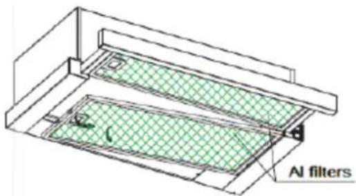
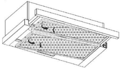
(1) Slide the front part of the cooker hood.
(2) The al filter should be detached first. Press the lock and pull it downward.
(3) Take out the carbon filter by rotating the carbon filter anti-clockwise.
(4) Replace the new carbon filter.
natural_image
Technical line drawing of a mechanical or architectural component with grid-patterned structure (no text or symbols)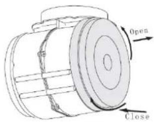
NOTE:
- Make sure the filter is securely locked. Otherwise, it would loosen and cause dangerous.
- When activated carbon filter attached, the suction power will be lowered.
BULB REPLACEMENT
Important :
The bulb must be replaced by the manufacturer, its service agent or similarly qualified persons.
Always switch off the electricity supply carrying out any operations on the appliance. When handling bulb, make sure it is completely cool down before any direct contact to hands.
When handling globes hold with a cloth or gloves to ensure perspiration does not come in contact with the globe as this can reduce the life of the globe.
(1) Switch off the appliance and unplug it.
(2) Slide the front part of the cooker hood.
(3) The al filter should be detached first. Press the lock and pull it downward.
(4) Replace with same type of light.110-240V\~50Hz, MAX.2W LED
- ILCOS D code for this lamp is: DBS-2/65-H-120/33.
- Max wattage: 1X2 W
– Voltage range: AC 110-240 V - Dimensions:
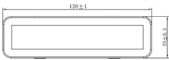
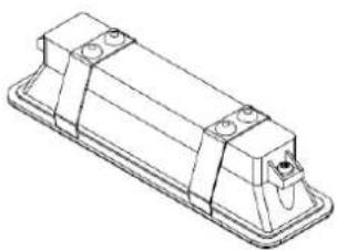
natural_image
Technical line drawing of a rectangular electronic component with mounting holes and a base plate (no text or symbols)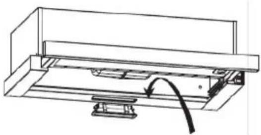
natural_image
Technical line drawing of a mechanical assembly with a curved arrow indicating motion (no text or symbols)ENVIRONMENTAL PROTECTION:
This appliance is labelled in accordance with European Directive 2012/19/EU regarding electric and electronic appliances (WEEE). The WEEE contain both polluting substances (that can have a negative effect on the environment) and base elements (that can be reused). It is important that the WEEE undergo specific treatments to correctly remove and dispose of the pollutants and recover all the materials. Individuals can play an important role in ensuring that the WEEE do not become an environmental problem; It is essential to follow a few basic rules:
- the WEEE should not be treated as domestic waste;
- the WEEE should be taken to dedicated collection areas managed by the town council or a registered company.
In many countries, domestic collections may be available for large WEEEs. When you buy a new appliance, the old one can be returned to the vendor who must accept it free of charge as a one-off, as long as the appliance is of an equivalent type and has the same functions as the purchased appliance.
NOTE:
The following shows how to reduce total environmental impact (e.g. energy use) of the cooking process).
(1) Install the cooker hood in a proper place where there is efficient ventilation.
(2) Clean the cooker hood regularly so as not to block the airway.
(3) Remember to switch off the cooker hood light after cooking.
(4) Remember to switch off the cooker hood after cooking.
INFORMATION FOR DISMANTLING
Do not dismantle the appliance in a way which is not shown in the user manual. The appliance could not be dismantled by user. At the end of life, the appliance should not be disposed of with household waste. Check with you Local Authority or retainer for recycling advice.
natural_image
Isometric line drawing of a rectangular storage or rack system with grid pattern and support brackets (no text or symbols)Obsah
natural_image
Illustration of a hot pot with steam rising and crossed by a firecracker (no text or symbols)natural_image
Illustration of a laboratory setup with a lamp, heating a test tube, and a control panel (no text or symbols)Co je vždy nutné:
MONTÁŽ KLÍNOVÉ KLAPKY
natural_image
Technical line drawing of a mechanical housing or enclosure with mounting brackets and a circular cutout, no text or symbols present.natural_image
Technical line drawing of a brick wall with a rectangular component and a circular feature, no text or symbols present.natural_image
Technical line drawing of a mechanical assembly with a cylindrical component and mounting base (no text or symbols)natural_image
Diagram of two electrical outlets with circular components and a dot symbol, labeled ① and ② (no text or symbols on the diagram itself)přepínač
natural_image
Abstract line drawing of a stylized figure interacting with a panel (no text or symbols)INSTALACE MŘÍŽKOVÝCH TUKOVÝCH FILTRŮ
natural_image
Technical line drawing of a mechanical or architectural component with grid pattern and directional arrows (no text or symbols)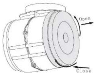
POZNÁMKA:
natural_image
Isometric line drawing of a two-tiered storage unit with grid pattern and support bracket (no text or symbols)Sommaire
natural_image
Illustration of a steaming pot and a fire with a crossed-out blade (no text or symbols)natural_image
Illustration of a laboratory setup with a lamp, test tube, and control unit (no text or symbols)À toujours faire :
INSTALLATION (murale)
natural_image
Technical line drawing of a rectangular enclosure with mounting feet and a circular vent, shown with an inset detail (no text or symbols)natural_image
Technical line drawing of a brick wall with a rectangular component mounted on a platform (no text or symbols)natural_image
Technical line drawing of a mechanical assembly with a cylindrical component and mounting base (no text or symbols)natural_image
Technical line drawing of a mechanical assembly with no visible text or symbolsnatural_image
Diagram of two electrical outlets with circular components and a dot symbol, labeled ① and ② (no text or symbols on the diagram itself)natural_image
Abstract line drawing of a stylized figure interacting with a geometric object (no text or symbols)REPLACEMENT DE L'AMPOULE
Important :
natural_image
Technical line drawing of a rectangular electronic component with mounting holes and a base plate (no text or symbols)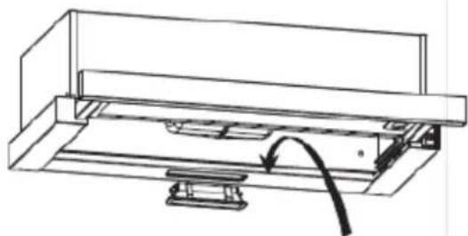
natural_image
Technical line drawing of a mechanical assembly with a curved arrow indicating motion (no text or symbols)PROTECTION DE L'ENVIRONNEMENT

natural_image
Isometric line drawing of a two-tiered storage unit with grid pattern and control panel (no text or symbols)Spis treści
natural_image
Illustration of a steaming pot with flames and a crossed-out knife (no text or symbols)natural_image
Illustration of a laboratory setup with a lamp, heating element, and control panel (no text or symbols)natural_image
Technical line drawing of a rectangular box mounted on a base plate, with a magnified inset showing a small bracket detail (no text or symbols present)natural_image
Technical line drawing of a brick wall with a rectangular component mounted on a base, showing internal structure and mounting features (no text or symbols)natural_image
Technical line drawing of a mechanical assembly with a cylindrical component and mounting base (no text or symbols)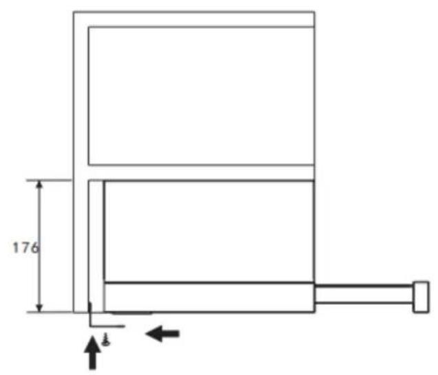
natural_image
Technical line drawing of a mechanical assembly with no visible text or symbolsnatural_image
Diagram of two electrical outlets with circular components and labeled parts (no text or symbols beyond labels)natural_image
Abstract line drawing of a stylized figure interacting with a wall and abstract shapes (no text or symbols)natural_image
Technical line drawing of a mechanical or architectural component with grid-patterned structure and two curved arrows indicating motion (no text or symbols)
UWAGA:
natural_image
Isometric line drawing of a rectangular enclosure or storage unit with internal grid pattern and support brackets (no text or symbols)Obsah
natural_image
Illustration of a steaming pot and fire with a crossed-out flame (no text or symbols)natural_image
Illustration of a laboratory setup with a lamp, beaker, and heating element (no text or symbols)natural_image
Technical line drawing of a rectangular enclosure with mounting brackets and a circular cutout, shown with an inset detail (no text or symbols)natural_image
Technical line drawing of a brick wall with a rectangular component mounted on a platform (no text or symbols)natural_image
Technical line drawing of a mechanical assembly with a cylindrical component and mounting base (no text or symbols)natural_image
Technical line drawing of a mechanical assembly with no visible text or symbolsKolískový prepínač
natural_image
Diagram of two electrical outlets with circular components and a grid pattern, labeled ① and ② (no text or symbols on the diagram itself)- Zasuňte sietovú zástrčku do zásuvky.
- Stlačte prepínač ①, kontrolka svieti; stlačte prepínač ① do polohy "0", kontrolka zhasne.
- Stlačte prepínač ② do polohy "I alebo Il", motor bude bežať na "nízkej alebo vysokej" rýchlosti (dve rýchlosti), prepnite prepínač do polohy "0", motor sa vypne.
- Ked' vytiahnete predný panel, spotrebič sa pripojí k napájaniu. Naopak, ked' zatlačíte panel spät, napájanie sa automaticky odpojí.
RIEŠENIE PROBLÉMOV
natural_image
Abstract line drawing of a stylized figure with geometric shapes and a circular element, no text or symbols present.INŠTALÁCIA DRÔTENÝCH TUKOVÝCH FILTROV
natural_image
Technical line drawing of a mechanical or architectural component with grid-patterned structure (no text or symbols)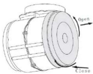
POZNÁMKA:
natural_image
Technical line drawing of a rectangular electronic component with mounting holes and a base plate (no text or symbols)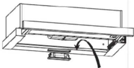
natural_image
Technical line drawing of a mechanical assembly with a curved arrow indicating motion (no text or symbols)OCHRANA ŽIVOTNÉHO PROSTREDIA
natural_image
Isometric line drawing of a rectangular storage or ventilation unit with grid pattern and support bracket (no text or symbols)Sadržaj
1......Bezbednosna uputstva
2....Montaža
3....Pokretanje aspiratora
4......Rešavanje problema
5. Održavanje i čišćenje
6. Zaštita životne sredine
BEZBEDNOSNA UPUTSTVA
Ovo uputstvo objašnjava kako se aspirator montira i koristi i molimo vas da ga pažljivo pročitate pre nego što počnete da koristite aspirator čak i ako ste već upoznati s ovim proizvodom. Ovo uputstvo treba čuvati na sigurnom mestu da bi se kasnije moglo koristiti.
natural_image
Illustration of a steaming lamp emitting steam with a crossed pen and inkwell (no text or symbols)- Ako je aspirator oštećen nemojte pokušavati da ga koristite.
•Nemojte flambirati jela ispod aspiratora. - OPREZ: Prilikom korišćenja kuhinjskih aparata pristupačni delovi aspiratora mogu postati vreli.
- Minimalna udaljenost između površine za kuvanje na šporetu i najnižeg dela aspiratora. (Kada se aspirator nalazi iznad uređaja na kom se koristi plin, udaljenost treba da bude najmanje 65 cm)
- Vazduh ne sme biti ispuštan kroz otvor koji se koristi za odvod dima iz uređaja na gas ili druga goriva.
natural_image
Illustration of a laboratory setup with a lamp, beaker, and heating element (no text or symbols)- Upozorenje: Pre pristupa terminalima sva strujna kola treba da budu isključena.
MONTAŽA (Postavljanje na zid)
- Odredite položaj rupa koje će se koristiti za kačenje aspiratora.
- Koristeći dva zavrtnja (4 mm x 10 mm) montirajte nosač profila L na vrh aspiratora
natural_image
Technical line drawing of a rectangular enclosure with mounting feet and a circular hole, shown with an inset detail (no text or symbols)- Aspirator se montira na zid pomoću 4 zavrtnja (4mm x 30mm) i tiplova.
Montirajte aspirator na zid tako što ćete zadnji deo aspiratora pričvrstiti za zid pomoću 2 zavrtnja (4mm x 30mm) i tiplova. Zatim, koristeći mali nosač profila L, pričvrstite aspirator za zid pomoću 2 zavrtnja (4mm x 30mm) i tiplova.
6002C(60)CM
- Pričvrstite nepovratni ventil na otvor za vazduh na aspiratoru.
natural_image
Technical line drawing of a brick wall with a rectangular box and mounting base (no text or symbols)MONTAŽA (na viseći element)
- Pričvrstite nepovratni ventil na otvor za vazduh na aspiratoru.

natural_image
Technical line drawing of a mechanical assembly with a cylindrical component and mounting base (no text or symbols)- Montirajte aspirator na viseći element pomoću 6 zavrtanja (4 x 35mm) i podloški.
60CM

Ako između zida i aspiratora postoji prazan prostor, možete postaviti nosač profila L na donju površinu aspiratora pomoću dva zavrtnja (3 x 12mm).
Postavljanje nosača profila L je stvar izbora.
natural_image
Technical line drawing of a mechanical assembly with no visible text or symbolsPreklopni prekidač
natural_image
Diagram of two electrical outlets with circular components and a dot symbol, labeled ① and ② (no text or symbols on the diagram itself)- Uključite utikač napojnog kabla u utičnicu.
-
Stavite prekidač ① na položaj, i lampica će se uključiti; stavite prekidač ① na položaj „0” i lampica će se isključiti.
-
Stavite prekidač ② na položaj „I、II “ i motor će raditi u dve brzine, „low、high “; stavite prekidač na položaj „0 “ i motor će se isključiti.
- Napajanje uređaja će se aktivirati nakon izvlačenja prednjeg dela aspiratora. Vraćanjem prednjeg dela aspiratora u prvobitni položaj, napajanje će automatski prekinuti.
REŠAVANJE PROBLEMA
| Kvar | Mogući uzrok | Rešenje |
| Svetlo svetli ali motor ne radi | Prekidač za ventilator je isključen | Postaviti prekidač za ventilator u odgovarajući položaj. |
| Prekidač za ventilator ne radi | Stupiti u kontakt sa servisnim centrom. | |
| Motor ne radi | Stupiti u kontakt sa servisnim centrom. | |
| Svetlo ne radi, motor ne radi | Problem s kućnim osiguračima | Vratiti/zameniti osigurače. |
| Strujni kabl labav ili isključen | Ponovo staviti kabl u utičnicu.Uključiti utičnicu. | |
| Curenje ulja | Nepovratni ventil i odvod nisu dobro zatvoreni | Skinuti nepovratni ventil i staviti zaptivač. |
| Spoj između poklopca i odvoda propušta | Skinuti odvod i zatvoriti ga. | |
| Svetla ne rade Sijalice | su pukle/neispravne | Zameniti sijalice u skladu sa ovimuputstvom. |
| Nedovoljno usisavanje | Udaljenost između aspiratora i grejne površine je prevelika | Podesiti aspirator na ispravnu udaljenost. |
| Aspirator je nagnut | Zavrtanj za pričvršćivanje nije dovoljno dotegnut | Dotegnuti zavrtanj kako bi aspirator stajao horizontalno. |
NAPOMENA:

natural_image
Abstract line drawing of a stylized figure interacting with a panel, no text or symbols present- Spoljašnje površine su podložne ogrebotinama i oštećenjima i zato vas molimo da sledite uputstva za čišćenje kako biste postigli najbolje moguće rezultate bez oštećenja.
UOPŠTENO
POVRŠINA KONTROLNE TABLE
Unutrašnja kontrolna tabla se može očistiti toplom sapunicom. Pre čišćenja krpa treba da bude čista i dobro isceđena. Koristite suvu meku krpu kako biste pokupili preostalu vlagu nakon čišćenja.
Važno
Koristite neutralne deterdžente i izbegavajte upotrebu jakih hemikalija za čišćenje, jakih deterdženata za domaćinstvo ili abrazivnih sredstava, jer to utiče na izgled uređaja i može ukloniti natpise na kontrolnoj tabli i zbog toga garancija proizvođača neće važiti.
MREŽASTI FILTERI ZA MASNOĆU
MONTIRANJE MREŽASTIH FILTERA ZA MASNOĆU
- Montaža filtera u četiri koraka.
- Postavite filter u svoje ležište u zadnjem delu aspiratora.
-
Pritisnite bravicu koja se nalazi na filteru.
-
Kada ste filter postavili u njegovo ležište oslobodite bravicu.
- Ponovite postupak dok ne montirate sve filtere.
natural_image
Technical line drawing of a mechanical or architectural component with grid pattern and directional arrows (no text or symbols)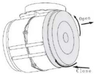
NAPOMENA:
natural_image
Isometric line drawing of a rectangular storage or rack system with a grid-patterned floor and side compartments (no text or symbols)Cuprins
natural_image
Illustration of a steaming cup and a crossed iron with a cross mark, no text or symbols presentnatural_image
Illustration of a laboratory setup with a lamp, beaker, and heating device (no text or symbols)natural_image
Technical line drawing of a rectangular enclosure with mounting feet and a circular hole, shown with an inset detail (no text or symbols)natural_image
Technical line drawing of a brick wall with a mounted fixture and a circular component (no text or symbols)natural_image
Technical line drawing of a mechanical housing with a circular top and mounting base (no text or symbols)natural_image
Abstract line drawing of a stylized animal figure with a circular element, no text or symbols presentGENERALITĂȚI
natural_image
Technical line drawing of a mechanical or architectural component with grid-patterned structure (no text or symbols)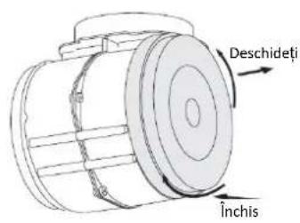
natural_image
Technical line drawing of a rectangular electronic component with mounting holes and a base plate (no text or symbols)
natural_image
Technical line drawing of a mechanical assembly with a curved arrow indicating motion (no text or symbols)PROTECTIA MEDIULUI:
natural_image
Technical line drawing of a rectangular storage or rack system with grid pattern and mounting bracket (no text or symbols)Sadržaj
1 Sigurnosne upute
2....Ugradnja
3 Počnite rabiti napu za štednjak
4....Rješavanje problema
5......Održavanje i čišćenje
6......Zaštita okoliša:
SIGURNOSNE UPUTE
U ovom priručniku opisane su pravilna ugradnja i uporaba vaše nape za štednjak; pažljivo ga pročitajte prije uporabe čak i ako vam je proizvod poznat. Priručnik treba čuvati na sigurnom mjestu da biste se njime mogli poslužiti i u budućnosti.
natural_image
Illustration of a steaming lamp illuminating flames with a crossed-out flame (no text or symbols)- Ako je napa za štednjak oštećena, ne pokušavajte je rabiti.
- Ne flambirajte hranu ispod nape za štednjak.
- OPREZ: Prilikom uporabe s uređajima za kuhanje dostupni dijelovi mogu se zagrijati.
- Najmanja udaljenost između potporne površine za posude za kuhanje na ploči za kuhanje i najnižeg dijela nape za štednjak. (Kada je napa za štednjak smještena iznad plinskog uređaja, ta udaljenost mora biti najmanje 65 cm)
- Zrak se ne smije ispustiti u dimnjak koji se rabi za ispušne plinove uređaja na plin ili druga goriva.
natural_image
Illustration of a laboratory setup with a lamp, beaker, and heating device (no text or symbols)UGRADNJA (Postavljanje na zid)
natural_image
Technical line drawing of a rectangular enclosure with mounting feet and a circular hole, shown with an inset detail (no text or symbols)- Napa za štednjak postavlja se na zid uz pomoć četiri vijka (4 mm x 30 mm) i zidnih tipli. Postavite napu za štednjak na zid stražnjom stranom nape za štednjak uz pomoć dva vijka (4 mm x 30 mm) i zidnih utikača. Zatim učvrstite napu za štednjak na zid uz pomoć dva vijka (4 mm x 30 mm) i zidnih utikača kroz mali nosač u obliku slova L.
natural_image
Technical line drawing of a brick wall with a rectangular base and circular opening, no text or symbols presentnatural_image
Technical line drawing of a mechanical assembly with a cylindrical component and mounting base (no text or symbols)Iz sigurnosnih razloga upotrebljavajte samo onu veličinu pričvrsnih ili postavnih vijaka koja je preporučena u ovom priručniku s uputama.
Ako ne ugradite vijke ili pričvrsni uređaj u skladu s ovim uputama, mogu nastati rizici povezani sa strujom.
POČNITE RABITI NAPU ZA ŠTEDNJAK
Ozibni prekidač

natural_image
Technical line drawing of a mechanical assembly with no visible text or symbolsOzibni prekidač
natural_image
Diagram of two electrical outlets with circular components and a numbered label (no text or symbols on the outlets themselves)- Umetnite strujni utikač u utičnicu.
- Ako je prekidač ① u položaju, svjetiljka se uključuje; ako je prekidač ① u položaju „0“, svjetiljka se isključuje.
-
Ako je prekidač ② u položaju „I, II“, motor je u načinu dviju brzina „mala, velika“, ako je u položaju „0“, motor se isključuje.
-
Napajanje se uključuje kada izvučete prednju ploču. U suprotnom, napajanje se automatski isključuje.
RJEŠAVANJE PROBLEMA
| Kvar | Mogući uzrok | Rješenje |
| Svjetlo je uključeno, ali motor ne radi | Isključen je prekidač za ventilator | Odaberite položaj prekidača za ventilator. |
| Kvar prekidača za ventilator | Obratite se servisnom centru. | |
| Kvar motora | Obratite se servisnom centru. | |
| Svjetlo ne radi, motor ne radi | Izgorjeli osigurači | Vratite osigurače u prvotno stanje / zamijenite ih. |
| Kabel za napajanje labav ili nije spojen | Ponovno utaknite kabel u utičnicu. Uključite utičnicu. | |
| Curenje ulja | Jednosmjerni ventil i otvor nisu čvrsto zatvoreni | Spustite jednosmjerni ventil i zabrtvite ga brtvilom. |
| Curenje iz spoja dimnjaka i poklopca | Spustite dimnjak i zabrtvite ga. | |
| Svjetla ne rade | Razbijene žarulje / žarulje u kvaru | Zamijenite žarulje sukladno ovoj uputi. |
| Nedovoljan usis | Prevelika udaljenost između nape za štednjak i plinske ploče | Postavite napu za štednjak na pravilnu udaljenost. |
| Naginje se napa za štednjak | Pričvrsni vijak nije dovoljno stegnut | Stegnite viseći vijak i stavite ga u vodoravan položaj. |

NAPOMENA:
Svi električni popravci ovog uređaja moraju biti izvršeni u skladu s lokalnim, državnim i saveznim zakonima. Obratite se servisnom centru ako imate bilo kakvih dvojbi prije poduzimanja bilo kojeg od gore navedenih koraka.
natural_image
Abstract line drawing of a stylized animal figure interacting with a wall (no text or symbols)- Vanjske su površine podložne ogrebotinama i abraziji; stoga se pridržavajte uputa za čišćenje da biste postigli najbolje rezultate bez oštećenja.
OPĆENITO
Čišćenje i održavanje treba provoditi dok je uređaj hladan, osobito prilikom čišćenja. Na površinama nemojte ostavljati lužnate ili kisele tvari (limunov sok, ocat itd.).
NEHRĐAJUĆI ČELIK
natural_image
Technical line drawing of a mechanical or architectural component with grid-patterned structure and directional arrows (no text or symbols)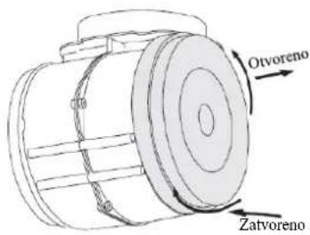
NAPOMENA:
natural_image
Technical line drawing of a rectangular electronic component with mounting holes and a base plate (no text or symbols)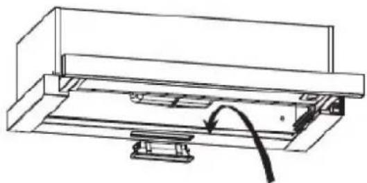
natural_image
Technical line drawing of a mechanical assembly with a curved arrow indicating motion (no text or symbols)ZAŠTITA OKOLIŠA:
Ovaj uređaj označen je u skladu s Direktivom 2012/19/EZ o otpadnoj električnoj i elektroničkoj opremi (OEEO). Otpadna električna i elektronička oprema sadrži onečišćujuće tvari (koje mogu imati negativan učinak na okoliš) i bazne elemente (koji se mogu ponovno upotrijebiti). Važno je posebno obraditi otpadnu električnu i elektroničku opremu da bi se ispravno uklonili i odložili onečišćivači i vratili svi materijali. Osobe mogu imati važnu ulogu u postizanju cilja da otpadna električna i elektronička oprema ne postane ekološki problem. Treba se pridržavati nekoliko osnovnih pravila: