USER MANUAL FIDC B265 CANDY
General Instructions
Product description
Display description
Cooking Modes
General notes on cleaning
Maintenance
Troubleshooting
Installation
Safety Indications
- During cooking, moisture may condense inside the oven cavity or on the glass of the door. This is a normal condition. To reduce this effect, wait 10–15 minutes after turning on the power before putting food inside the oven. In any case, the condensation disappears when the oven reaches the cooking temperature.
- Cook the vegetables in a container with a lid instead of an open tray.
- Avoid leaving food inside the oven after cooking for more than 15/20 minutes.
- WARNING: the accessible parts can become hot when the oven is in use. Young children should be kept at a safe distance.
- WARNING: the accessible parts can become hot when the grill is in use. Children should be kept at a safe distance.
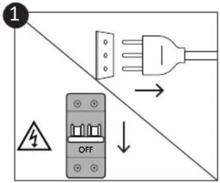
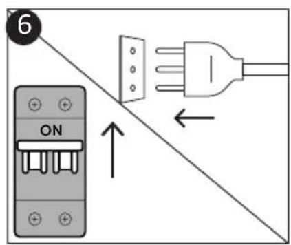
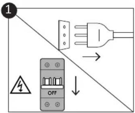
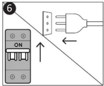
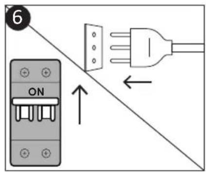
- Disconnect the appliance from the mains electricity supply before carrying out any work or maintenance.
- WARNING: in order to avoid any danger caused by the accidental resetting of the thermal interruption device, the appliance should not be powered by an external switching device, such as a timer, or be connected to a circuit that is regularly switched on and off.
- Children under 8 should be kept at a safe distance from the appliance if not continuously supervised. • Children should not play with the appliance.
- The appliance can be used by those aged 8 or over and by those with limited physical, sensorial or mental capacities, without experience or knowledge of the product, only if supervised or provided with instruction as to the operation of the appliance, in a safe way with awareness of the possible risks.
- Cleaning and maintenance should not be carried out by unsupervised children.
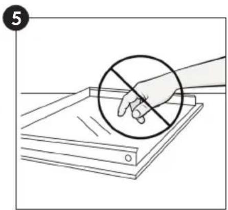
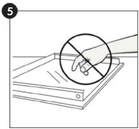
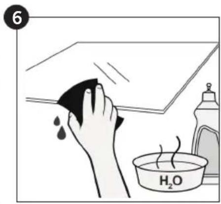
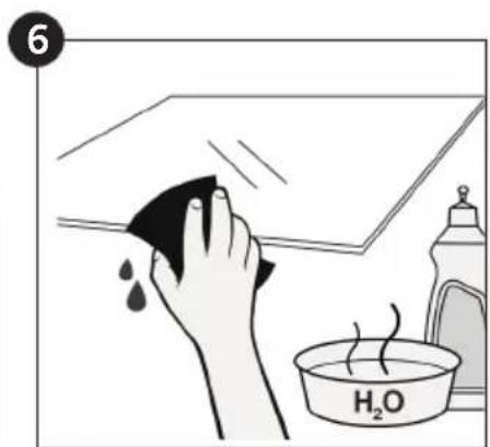
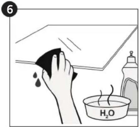
- Do not use rough or abrasive materials or sharp metal scrapers to clean the oven door glasses, as they can scratch the surface
and cause the glass to shatter.
- The oven must be switched off before removing the removable parts. After cleaning, reassemble them according the instructions.
- Only use the meat probe recommended for this oven.
- Do not use a steam cleaner or high pressure spray for cleaning operations.
- WARNING: the appliance and accessible parts become hot during use. Be careful not to touch any hot parts.
- WARNING: ensure that the appliance is switched off before replacing the bulb, to avoid the possibility of electric shocks.
- IF THE OVEN IS PROVIDED BY THE MANUFACTURER WITHOUT PLUG:
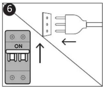
THE APPLIANCE MUST NOT BE CONNECTED TO THE POWER SOURCE USING PLUG OR SOCKETS, BUT MUST BE DIRECTLY CONNECTED TO THE SUPPLY MAINS. The connection to the power source must be carried out by a suitably qualified professional. In order to have an installation compliant to the current safety legislation the oven must be connected only placing an omnipolar breaker, with contact separation compliant to the requirements for overvoltage category III, between the appliance and the power source. The omnipolar breaker must bear the maximum connected load and must be in line with current legislation. The yellow-green earth cable should not be interrupted by the breaker. The omnipolar breaker used for the connection must be easily accessible when the appliance is installed.
The connection to the power source must be carried out by a suitably qualified professional considering the polarity of the oven and of the power source.
The disconnection must be achieved incorporating a switch in the fixed wiring in accordance with the wiring rules
- IF THE OVEN IS PROVIDED BY THE MANUFACTURER WITH PLUG:
The socket must be suitable for the load indicated on the tag and must have a ground contact connected and in operation. The earth conductor is yellow-green in color. This operation should be carried out by a suitably qualified professional. In case of incompatibility between the socket and the appliance plug, ask a qualified electrician to substitute the socket with another suitable type. The plug and the socket must conform to the current norms of the installation country. Connection to the power source can also be made by placing an omnipolar breaker, with contact separation compliant with the requirements for overvoltage category III, between the appliance and the power source that can bear the maximum connected load and that is in line with current legislation. The yellow-green earth cable should not be interrupted by the breaker. The socket or omnipolar breaker used for the connection should be easily accessible when the appliance is installed.
The disconnection may be achieved by having the plug accessible or by incorporating a switch in the fixed wiring in accordance with the wiring rules.
- If the power cable is damaged, it should be substituted with a cable or special bundle available from the manufacturer or by contacting the customer service department. The type of power cable must be H05V2V2-F. This operation should be carried out by a suitably qualified professional. The earth conductor (yellow-green) must be approximately 10 mm longer than the other conductors. For any repairs, refer only to the Customer Care Department and request the use of original spare parts.
- Failure to comply with the above can compromise the safety of the appliance and invalidate the guarantee.
- Any excess of spilled material should be removed before cleaning.
- A long power supply failure during an occurring cooking phase may cause a malfunction of the monitor. In this case, contact customer service.
- The appliance must not be installed behind a decorative door in order to avoid overheating.
- When you place the shelf inside, make sure that the stop is directed upwards and in the back of the cavity. The shelf must be inserted completely into the cavity.
- When inserting the grid tray, pay attention that the anti-slide edge is positioned rearwards and upwards.
- WARNING: Do not line the oven walls with aluminium foil or single-use protection available from stores. Aluminium foil or any other protection, in direct contact with the hot enamel, risks melting and deteriorating the enamel of the insides.
- WARNING: Never remove the oven door seal.
- CAUTION: Do not refill the cavity bottom with water during cooking or when the oven is hot.
- No additional operation/setting is required in order to operate the appliance at the rated frequencies.
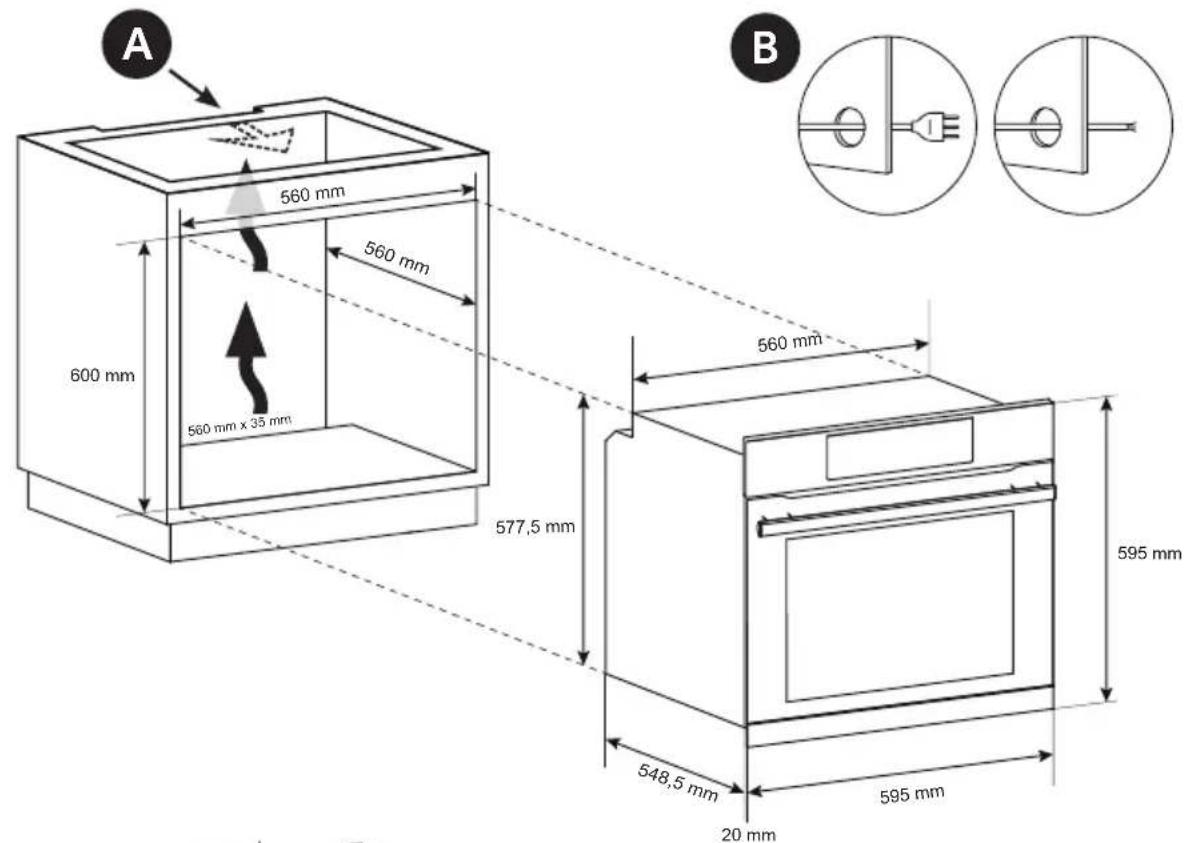
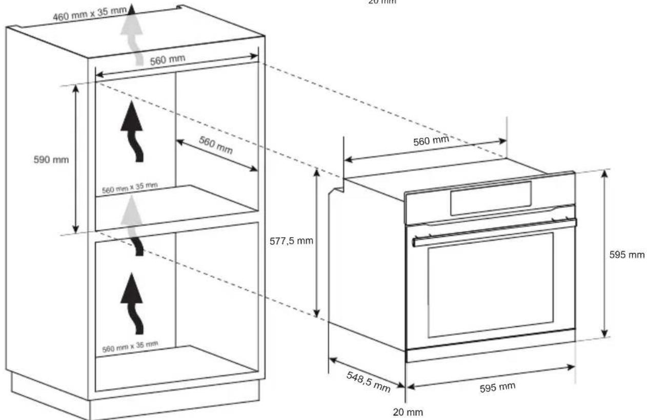
- The oven can be located high in a column or under a worktop. Before fixing, you must ensure good ventilation in the oven space to allow proper circulation of the fresh air required for cooling and protecting the internal parts. Make the openings specified on last page according to the type of fitting.
- WARNING: Do not place food directly on the oven racks. Always use parchment paper and/or suitable baking trays or pans.
General Instructions
We thank you for choosing one of our products. For the best results with your oven, you should read this manual carefully and retain it for future reference. Before installing the oven, take note of the serial number so that you can give it to customer service staff if any repairs are required. Having removed the oven from its packaging, check that it has not been damaged during transportation. If you have doubts, do not use the oven and refer to a qualified technician for advice. Keep all of the packaging material (plastic bags, polystyrene, nails) out of the reach of children. When the oven is switched on for the first time, strong smelling smoke can develop, which is caused by the glue on the insulation panels surrounding the oven heating for the first time. This is absolutely normal and, if it occurs, you should wait for the smoke to dissipate before putting food in the oven. The manufacturer accepts no responsibility in cases where the instructions contained in this document are not observed.
NOTE: the oven functions, properties and accessories cited in this manual will vary, depending on the model you have purchased.
Safety Indications
Only use the oven for its intended purpose, that is only for the cooking of foods; any other use, for example as a heat source, is considered improper and therefore dangerous. The manufacturer cannot be held responsible for any damage resulting from improper, incorrect or unreasonable usage.
The use of any electrical appliance implies the observance of some fundamental rules:
- do not pull on the power cable to disconnect the plug from the socket;
- do not touch the appliance with wet or damp hands or feet;
- in general the use of adaptors, multiple sockets and extension cables is not recommended;
- in case of malfunction and/or poor operation, switch off the appliance and do not tamper with it.
Electrical Safety
ENSURE THAT AN ELECTRICIAN OR QUALIFIED TECHNICIAN MAKES THE ELECTRICAL CONNECTIONS. The power supply to which the oven is connected must conform with the laws in force in the country of installation. The manufacturer accepts no responsibility for any damage caused by the failure to observe these instructions. The oven must be connected to an electrical supply with an earthed wall outlet or a disconnector with multiple poles, depending on the laws in force in the country of installation. The electrical supply should be protected with suitable fuses and the cables used must have a transverse section that can ensure correct supply to the oven.
CONNECTION
The oven is supplied with a power cable that should only be connected to an electrical supply with 220-240 Vac power between the phases or between the phase and neutral. Before the oven is connected to the electrical supply, it is important to check:
- power voltage indicated on the gauge;
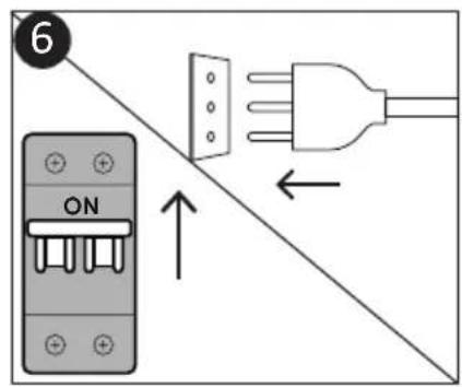
- the setting of the disconnector.
The grounding wire connected to the oven's earth terminal must be connected to the earth terminal of the power supply.
WARNING
Before connecting the oven to the power supply, ask a qualified electrician to check the continuity of the power supply's earth terminal. The manufacturer accepts no responsibility for any accidents or other problems caused by failure to connect the oven to the earth terminal or by an earth connection that has defective continuity.
NOTE: as the oven could require maintenance work, it is advisable to keep another wall socket available so that the oven can be connected to this if it is removed from the space in which it is installed. The power cable must only be substituted by technical service staff or by technicians with equivalent qualifications.
A low light around the central main switch could be present when the oven is off. This is a normal behavior. It can be removed just by turning the plug upside down or swapping the supply terminals.
Recommendations
After each use of the oven, a minimum of cleaning will help keep the oven perfectly clean.
Do not line the oven walls with aluminium foil or single-use protection available from stores. Aluminium foil or any other protection, in direct contact with the hot enamel, risks melting and deteriorating the enamel of the insides. In order to prevent excessive dirtying of your oven and the resulting strong smokey smells, we recommend not using the oven at very high temperature. It is better to extend the cooking time and lower the temperature a little. In addition to the accessories supplied with the oven, we advise you only use dishes and baking moulds resistant to very high temperatures.
Installation
The manufacturers have no obligation to carry this out. If the assistance of the manufacturer is required to rectify faults arising from incorrect installation, this assistance is not covered by the guarantee. The installation instructions for professionally qualified personnel must be followed. Incorrect installation may cause harm or injury to people, animals or belongings. The manufacturer cannot be held responsible for such harm or injury.
The oven can be located high in a column or under a worktop. Before fixing, you must ensure good ventilation in the oven space to allow proper circulation of the fresh air required for cooling and protecting the internal parts. Make the openings specified on last page according to the type of fitting.
First Use
PRELIMINARY CLEANING; Clean the oven before using for the first time. Wipe over external surfaces with a damp soft cloth. Wash all accessories and wipe inside the oven with a solution of hot water and washing up liquid. Set the empty oven to the maximum temperature and leave on for about 1 hour, this will remove any lingering smells of newness.
Product description
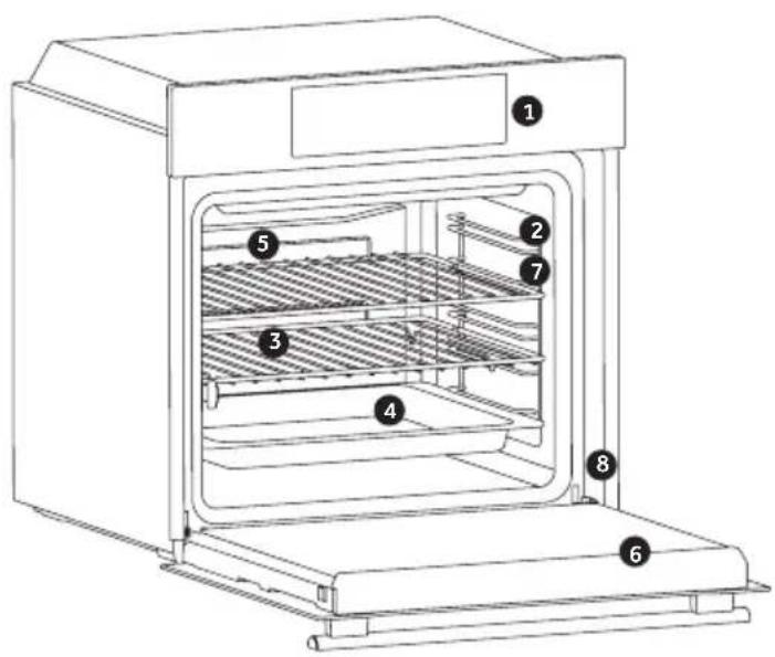
- Control panel
- Shelf positions (lateral wire grid if included)
- Grids
- Trays
- Fan (if present)
- Oven door
- Lateral wire grids (if present: only for flat cavity)
8. Serial number
Write here your serial number for future reference.
ACCESSORIES (depends on model)
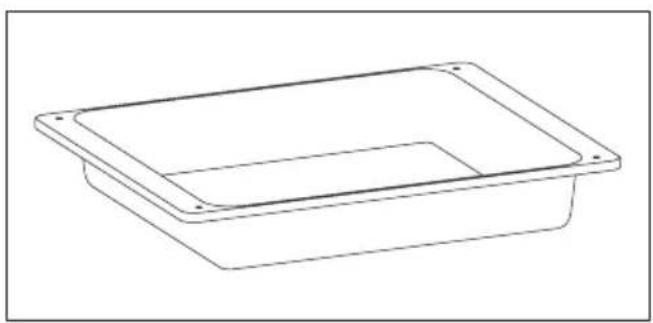
Drip tray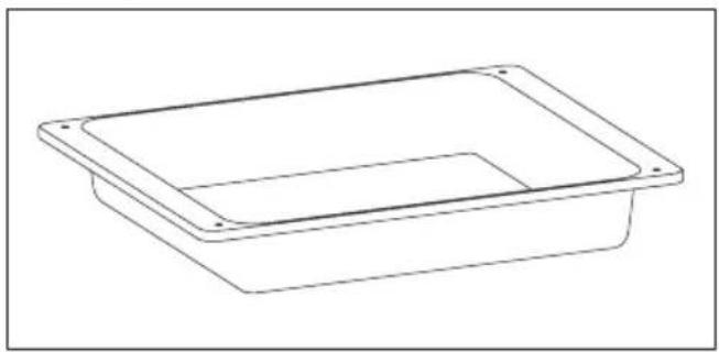
The dripping pan collects the residues that drip during cooking
Lateral wire grids (only if present)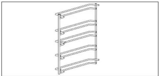
Located on both sides of the oven cavity, holds metal grills and drip pans.
Metal grid
The oven racks are not suitable for direct contact with food. Please use appropriate baking trays or baking paper.
Telescopic guides (only if present)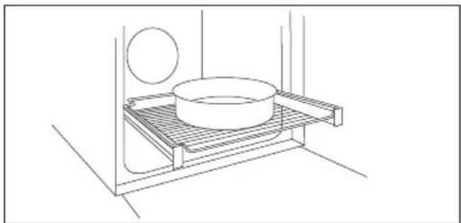
Two guide rails which facilitate the cooking status check as they allow easily the extraction and repositioning of trays and grids inside the oven cavity.
NOTE: Do not place food directly on the oven racks. Always use parchment paper and/or suitable baking trays or pans.
Meat probe (only if present)
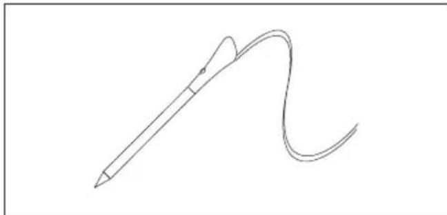
Measures the internal temperature of food during cooking. Insert into the hole on the top of the cavity. Should be inserted while oven is cool.
WARNINGS:
- Do not preheat or start cooking before properly inserting the meat probe.
- Do not try to insert the meat probe in frozen food.
Catalytic panels (only if present)
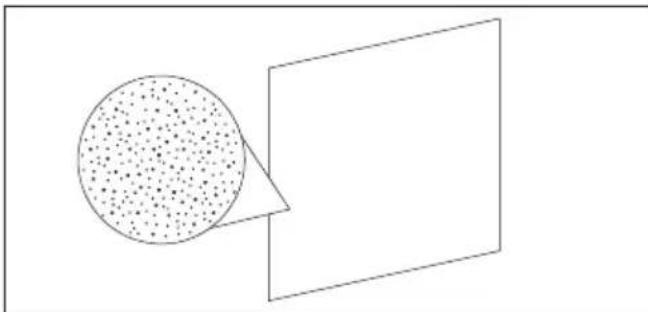
Special panels coated with enamel, made with a microporous structure to turn fat into gaseous elements that are easy to remove. Replace after 3 years of use (at 2/3 cooking cycles per week).
Softclose (only if present)
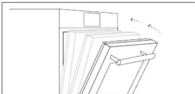
Hinges which ensure an automatic soft and smooth movement during the closing phase of the oven door.
Turnspit (only if present)
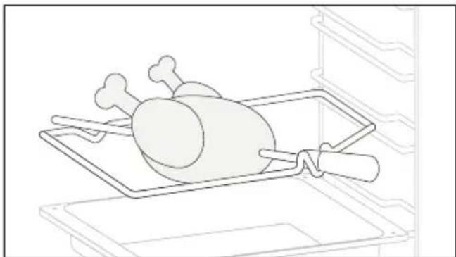
No pre-heating is required for rotisserie cooking. Cook with the door closed.
- Unscrew the hooks
- Insert the spit into the meat to be cooked
- Secure the meat with the hooks
- Tighten the screws
- Insert the spindle into the hole where the motor is located.
- Remove the handle and use it at the end of cooking to avoid burns when taking the food out of the oven
Grill pan set (only if present)
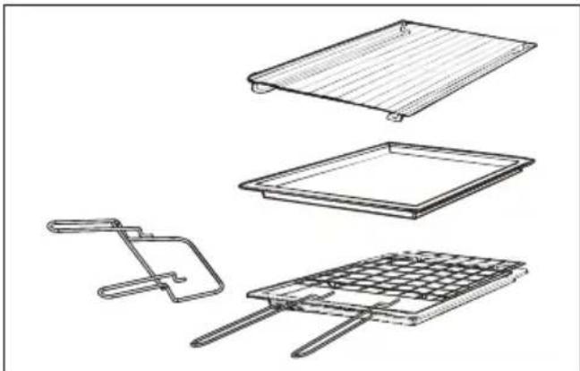
The simple shelf can take moulds and dishes.
The tray holder shelf is especially good for grilling things.
Use it with the drip tray.
The special profile of the shelves means they stay horizontal even when pulled right out. There is no risk of a dish sliding or spilling.
The drip tray catches the juices from grilled foods. It is only used with the Grill, Rotisserie, or Fan Assisted Grill; remove it from the oven for other cooking methods.
Never use the drip tray as a roasting tray as this creates smoke and fat will spatter your oven making it dirty.
The tray holder
The tray holder shelf is ideal for grilling. Use it in conjunction with the drip tray. A handle is included to assist in moving both accessories safely. Do not leave the handle inside the oven.
Chef panel (only if present)
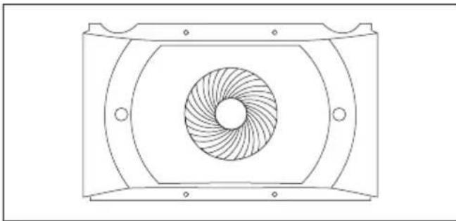
An air conveyor that increases air circulation inside the oven. This enables improved cooking performance, more even cooking of food at all temperatures, shorter cooking times and, lastly, an even temperature distribution inside the oven.
Airfry Tray (only if present)
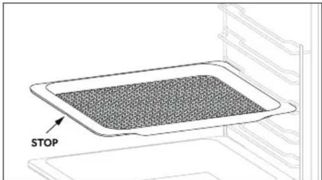
The airfry tray ensures that hot air reaches the food evenly and tridimensionally, resulting in a crispier exterior while maintaining tenderness inside. A baking tray can be optionally placed at L1 to collect juices or breadings.
Low power consumption data according to Commission Regulation (EU) 2023/826
Power consumption of the product in standby mode condition with information or status display: 0.8 W. Period after which the equipment reaches automatically standby mode condition with information or status display: 20 min.
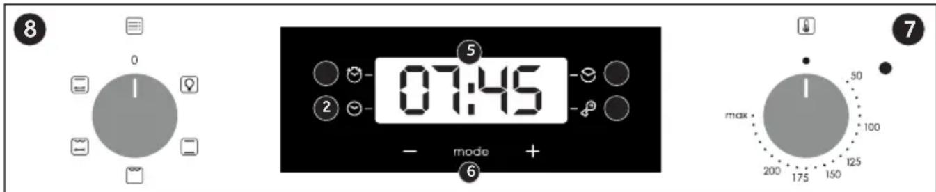
- Minute minder
- Clock setting
- Cooking time
- Child Lock
- Temperature or clock display
- LCD display adjustment controls
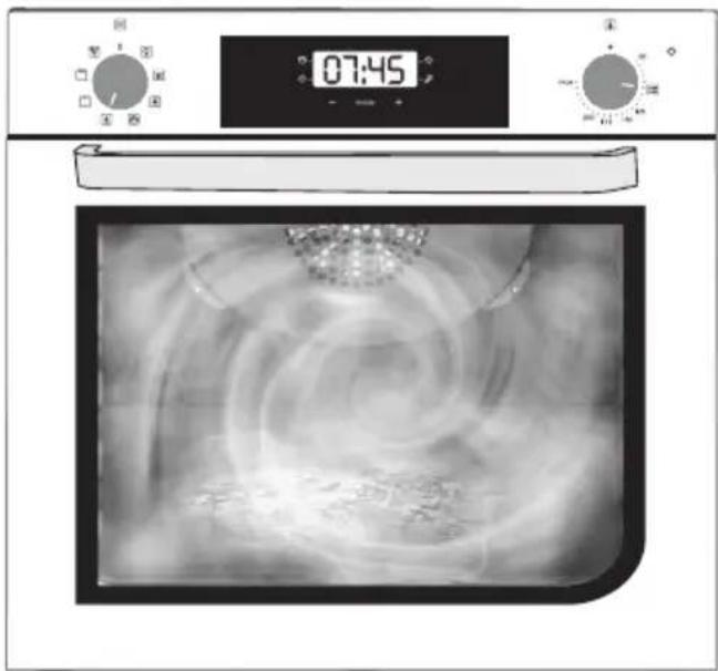
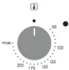
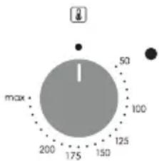
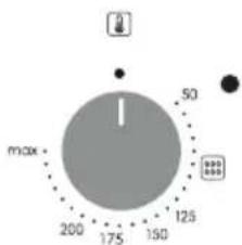
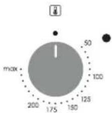
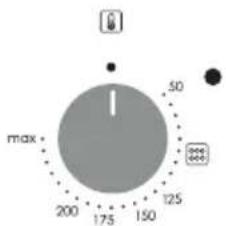
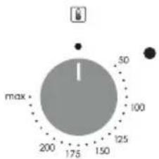
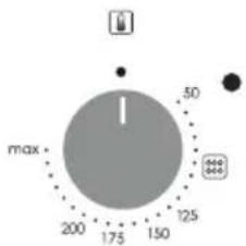
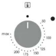
- Thermostat selector knob
- Function selector knob
WARNING: the first operation to carry out after the oven has been installed or following the interruption of power supply (this is recognizable the display pulsating and showing 12:00) is setting the correct time. This is achieved as follows.
- Push the central button 4 times
- Set time with "-" "+" buttons.
- Release all buttons.
ATTENTION: The oven will only operate providing the clock is set.
Use of touch control clock programmer (depends on model)
| FUNCTION HOW TO ACTIVATE | HOW TO DEACTIVATE | WHAT IT DOES WHY IT IS NEEDED |
| KEY LOCK | ·Child Lock function is activated by touching Set (+) for a minimum of 5 seconds. From this moment on all other functions are locked, LED of child lock turn on, the display will flash STOP and present time intermittently | Child Lock function is deactivated by touching touchpad Set (+) again for a minimum of 5 seconds. From this moment LED of child lock turn off and all functions are selectable again. | | |
| MINUTE MINDER | ·Push the central button 1 times·Press the buttons “-” “+” to set the required time·Release all the buttons | ·When the set time as elapsed an audible alarm is activated (this alarm will stop on its own, however it can be stopped immediately by pressing the button) SELECT. | ·Sounds an alarm at the end of the set time.·During the process, the display shows the remaining time. | ·Allows to use the oven as alarm clock (could be activated either with operating the oven or with out operating the oven) |
| COOKING TIME | ·Push the central button 2 times·Press the buttons “-” or “+” to set the length of cooking required·Release all buttons·Set the cooking function with the oven function selector | ·Push any button to stop the signal. Push the central button to return to the clock function. | ·It allows to preset the cooking time required for the recipe chosen.·To check how long is left to run press the SELECT button 2 times.·To alter/change the preset time press SELECT and “-” “+” buttons. | ·When the time is elapsed the oven will switch off automatically.Should you wish to stop cooking earlier either turn the function selector to 0, or set time to 0:00(SELECT and “-” “+” buttons) |
Low power consumption data according to Commission Regulation (EU) 2023/826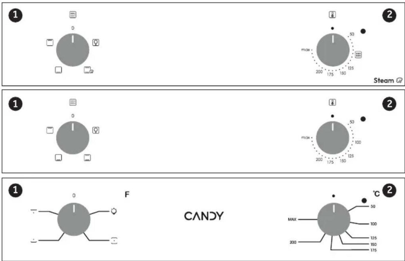
- Function selector knob
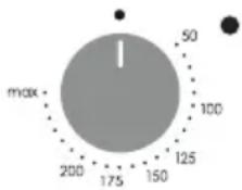
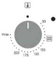
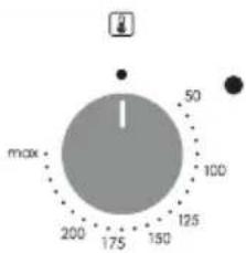
- Thermostat selector knob
Cooking Modes (depends on model)
| Symbol | T°C default | T°C range | Function |
 | | | LAMP: Turns on the oven light. |
 | 220 50 ÷ MAX | * CONVENTIONAL: Both top and bottom heating elements are used. Preheat the oven for about ten minutes. This method is ideal for all traditional roasting and baking. Place the food and its dish on a shelf in mid position. |
 | 210 50 ÷ MAX | BOTTOM HEATING: Using the lower element. Ideal for cooking all pastry based dishes. Use this for flans, quiches, tarts, pate and any cooking that needs more heat from below |
 | 220 50 ÷ MAX | CONVENTIONAL + STEAM: Both top and bottom heating elements are used. Preheat the oven for about ten minutes. This method is ideal for all traditional roasting and baking. Place the food and its dish on a shelf in mid position. This function also provides steam-assisted cooking, which requires adding 100ml of water in the cavity when the oven is cold and turning the knob to this function. Do not use preheating for this feature. Steam mode can be used to obtain a crispier crust and a glossier surface for, especially bakeries. |
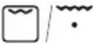 | 230 50 ÷ MAX | GRILL: Ideal for big quantities of sausages, steaks and toast bread. The entire area below the grill element becomes hot. Use with the door closed. Turn food two thirds of the way through cooking (If necessary). When grilling toasts, use max temperature in shelf position 5 without preheating. |
 | 220 50 ÷ MAX | GRILL + TURNSPIT: the turnspit is used with the door closed. The heating temperature can be modified as needed. It is best to cook only medium-sized pieces on the turnspit. Ideal for rediscovering all the flavors of old-fashioned rotisserie. Preheating is not done for turnspit cooking. |
 | 220 50 ÷ MAX | NATURAL CONVECTION WITH TURNSPIT: The bottom and top heaters of the oven are in operation. It's cooking traditional suitable for roasts and poultry, and not requiring the addition of fat. |

Scan the QR code and discover how to use it at best to prepare your favourite recipes.
General notes on cleaning
The lifecycle of the appliance can be extended through regular cleaning. Wait for the oven to cool before carrying out manual cleaning operations. Never use abrasive detergents, steel wool or sharp objects for cleaning, so as to not irreparably damage the enamelled parts. Use only water, soap or bleach-based detergents (ammonia).
GLASS PARTS
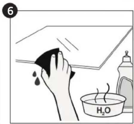
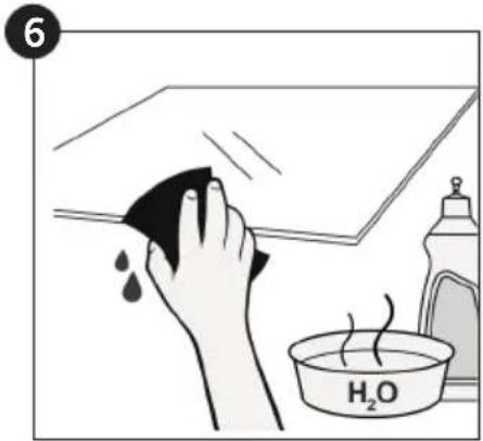
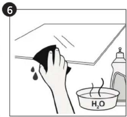
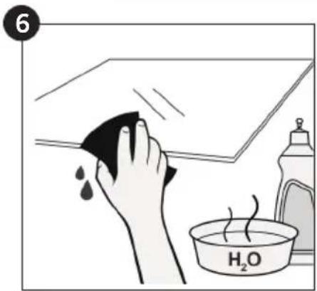
It is advisable to clean the glass window with absorbent kitchen towel after every use of the oven. To remove more obstinate stains, you can use a detergent-soaked sponge, well wrung out, and then rinse with water.
OVEN WINDOW SEAL
If dirty, the seal can be cleaned with a slightly
damp sponge.
ACCESSORIES
Clean accessories with a wet, soapy sponge before rinsing and drying them: avoid using abrasive detergents.
DRIP PAN
After using the grill, remove the pan from the oven. Pour the hot fat into a container and wash the pan in hot water, using a sponge and washing-up liquid.
If greasy residues remain, immerse the pan in water and detergent. Alternatively, you can wash the pan in the dishwasher or use a commercial oven detergent. Never put a dirty pan back into the oven.
Maintenance (depends on model)
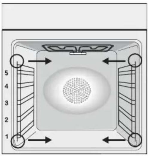
REMOVAL AND CLEANING OF THE SIDE RACKS
- Remove the wire racks by pulling them in the direction of the arrows (see below)
- To clean the wire racks either put them in the dishwasher or use a wet sponge, ensuring that they are dried afterwards.
- After the cleaning process install the wire racks in reverse order.
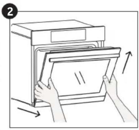
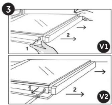
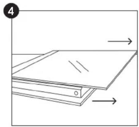
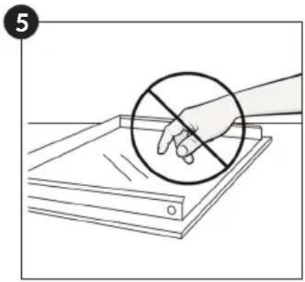
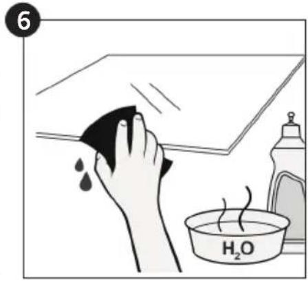
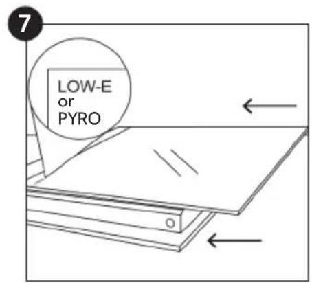
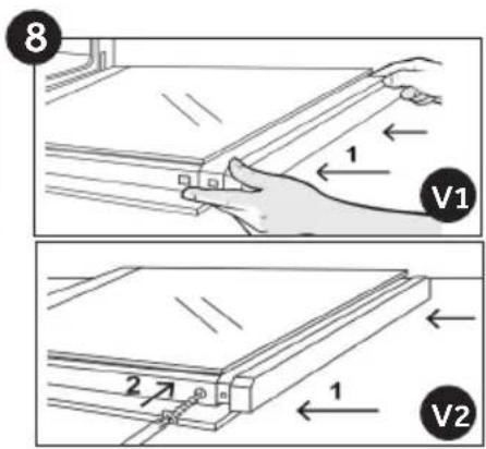
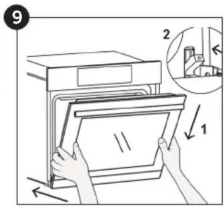
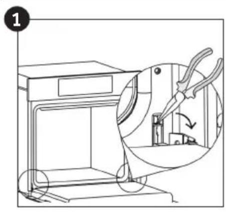
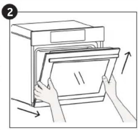
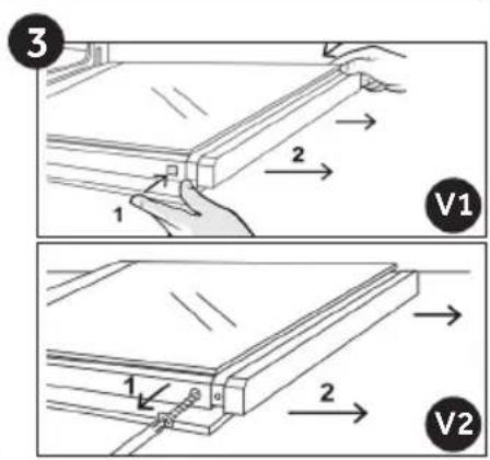
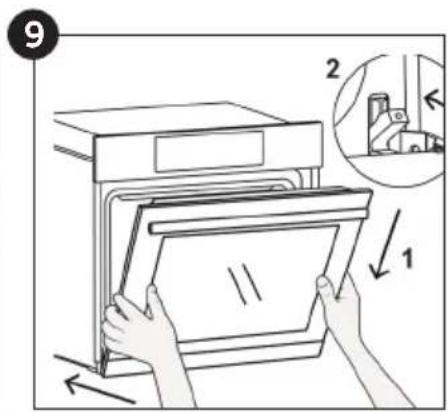
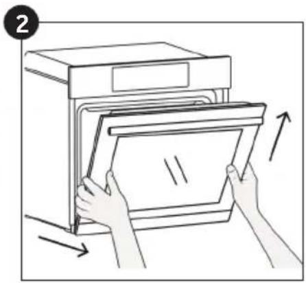
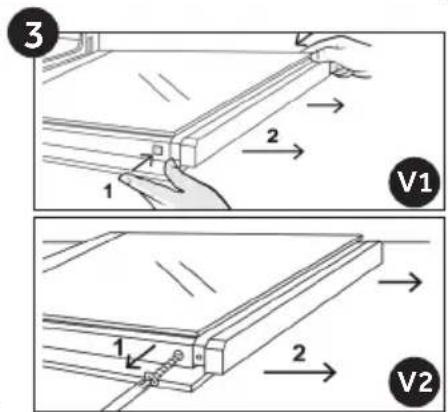
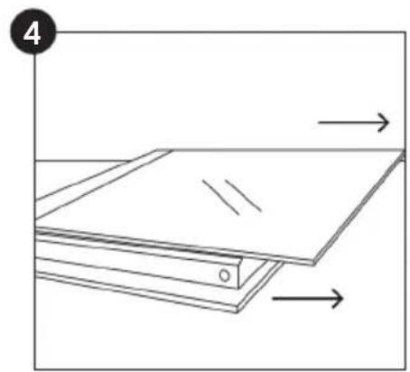
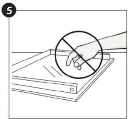
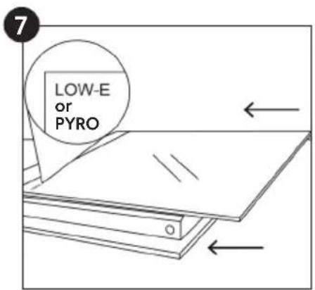
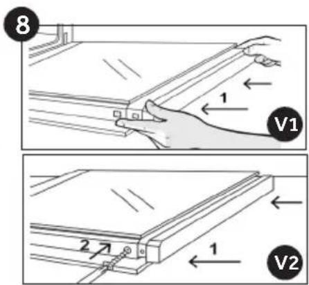
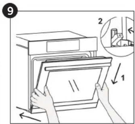
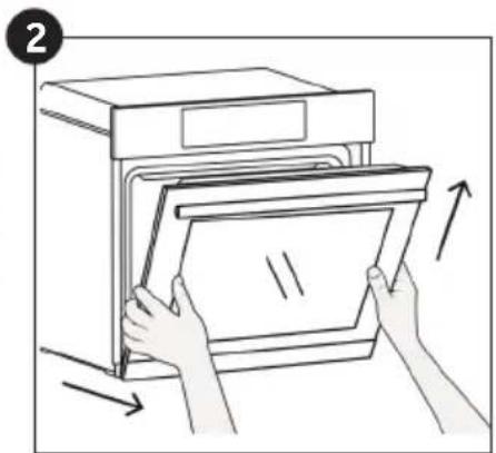
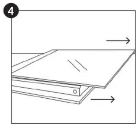
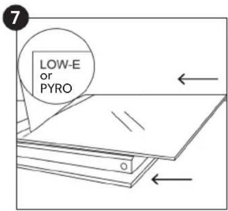
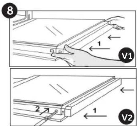
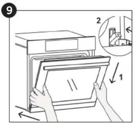
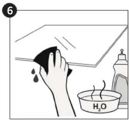
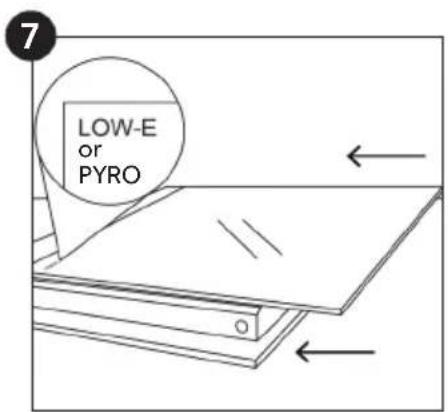
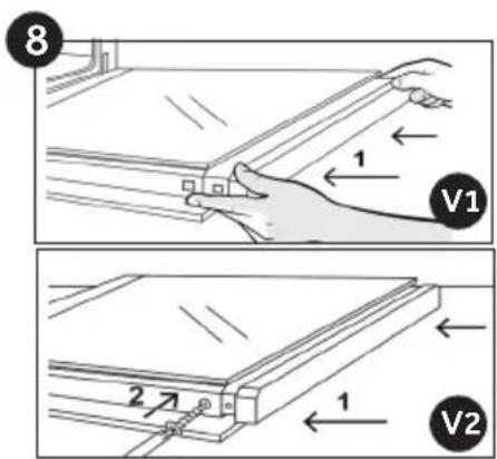
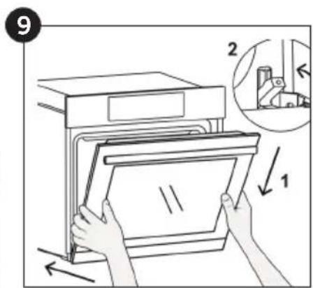
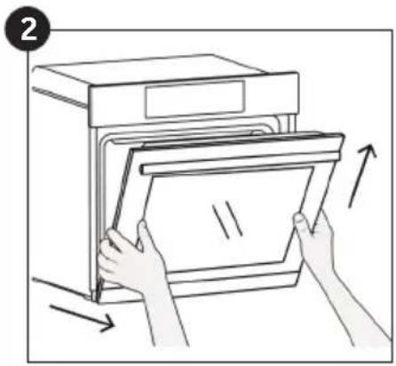
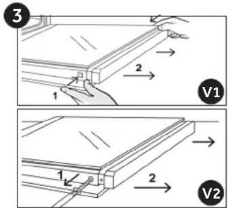
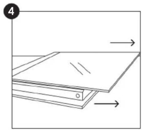
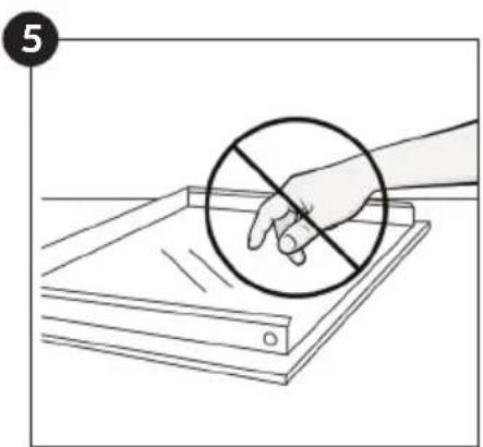
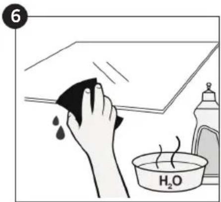
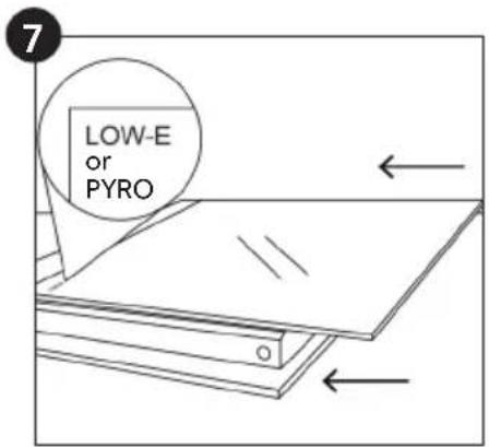
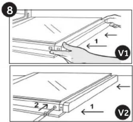
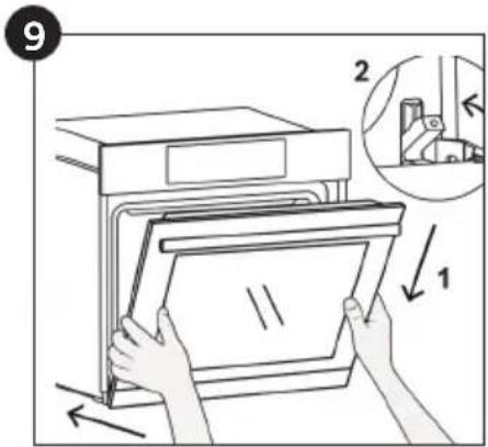
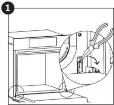
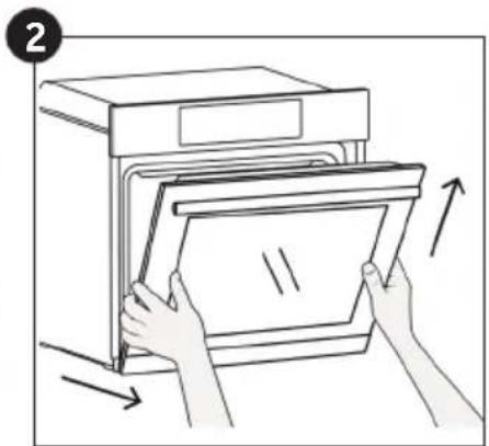
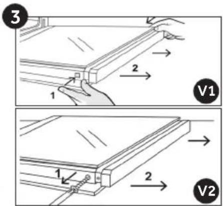
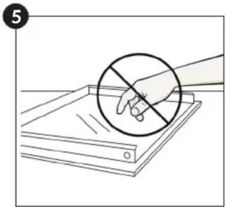
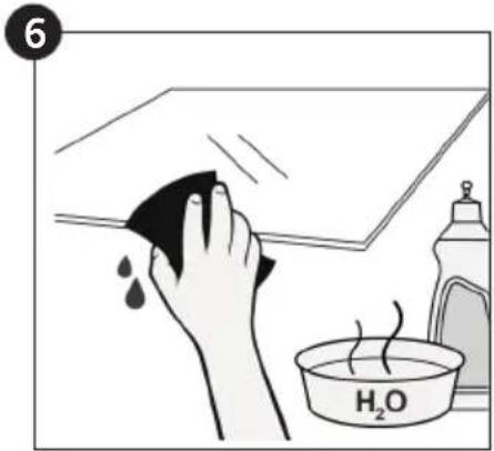
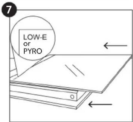
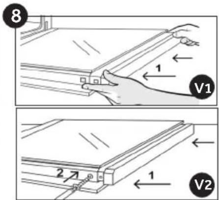
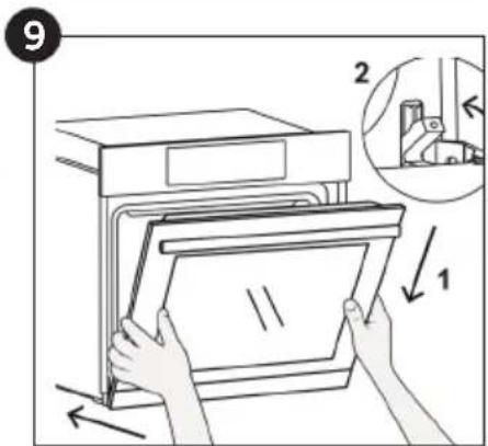
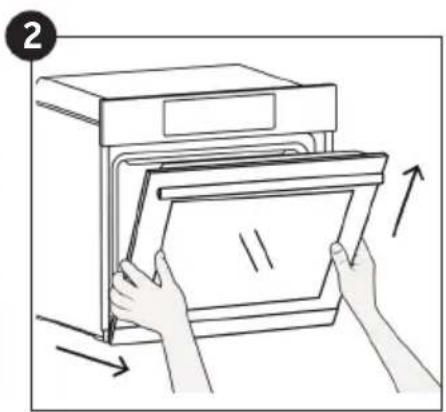
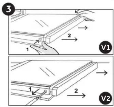
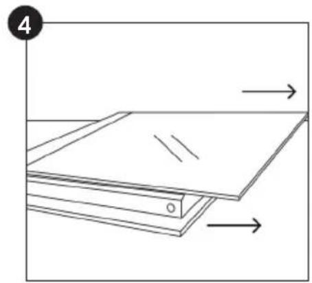
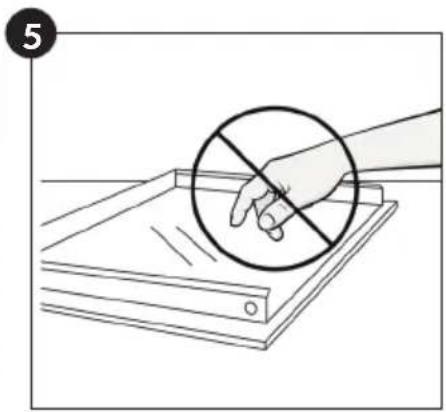
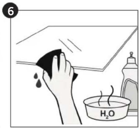
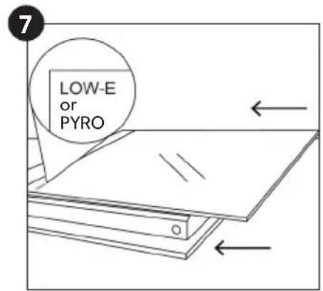
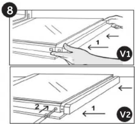
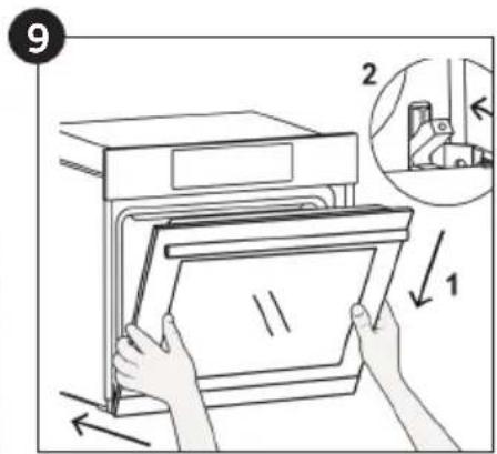
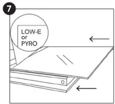
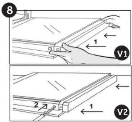
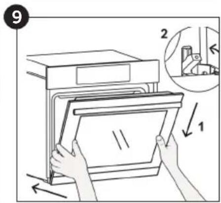
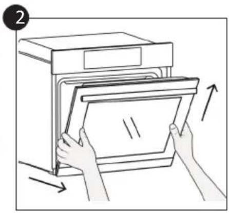
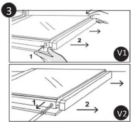
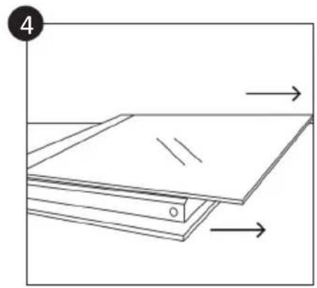
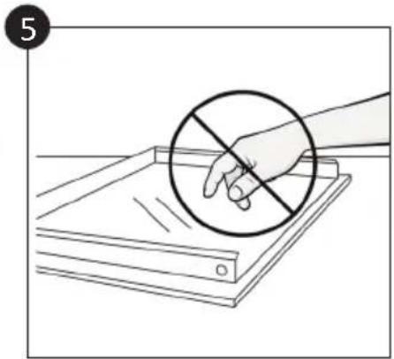
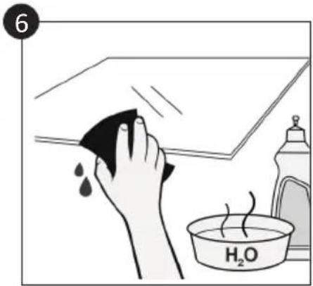
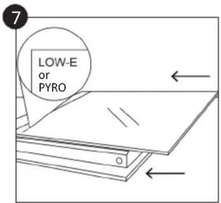
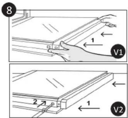
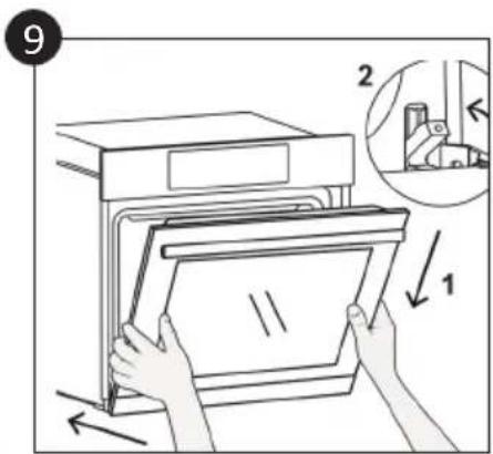
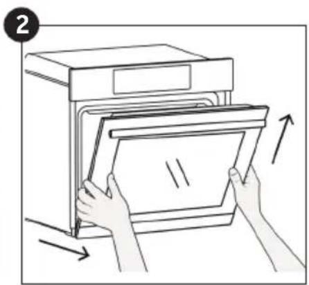
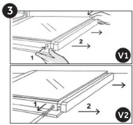
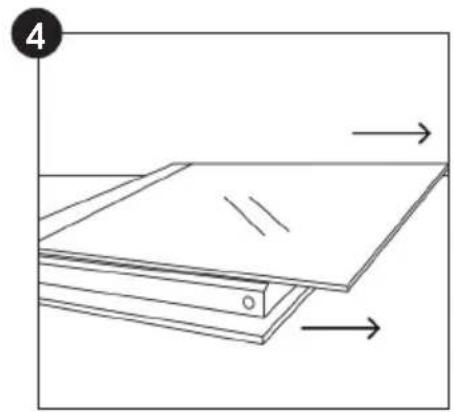
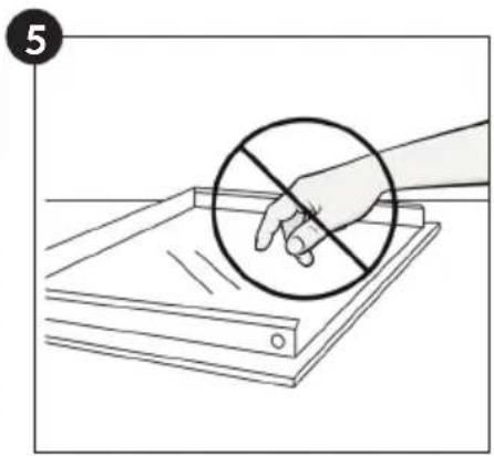
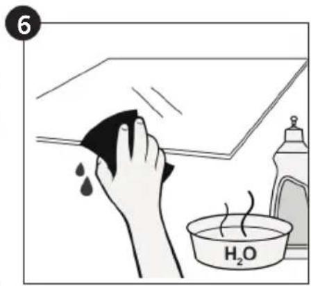
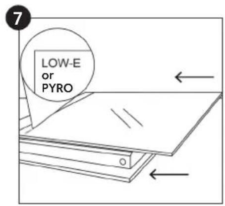
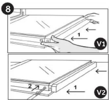
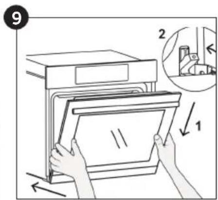
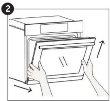
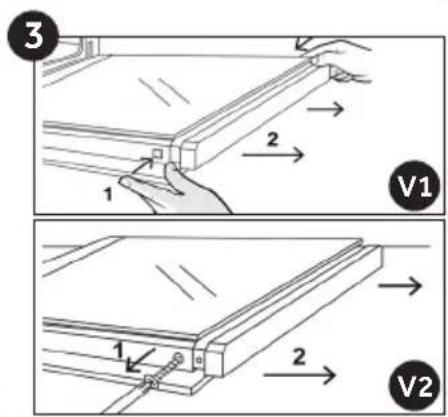
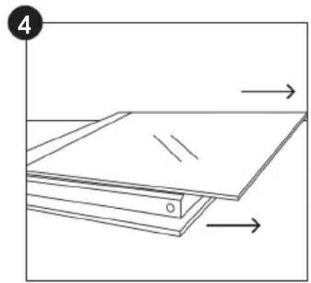
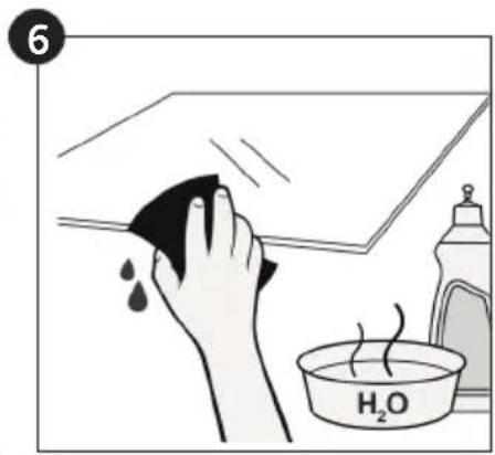
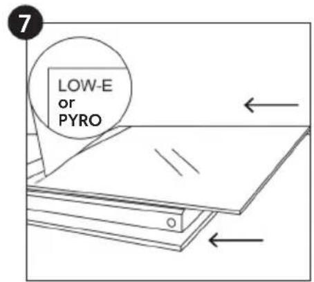
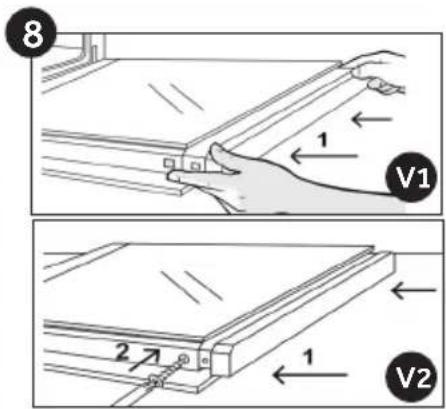
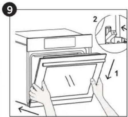
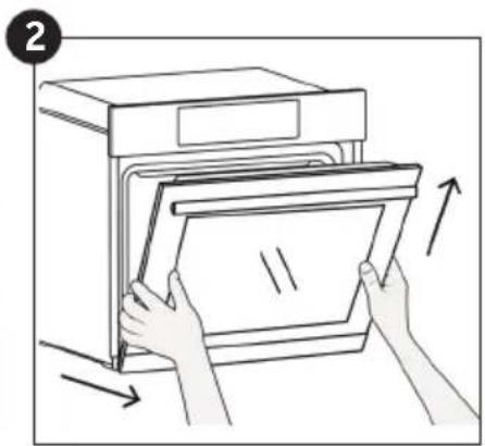
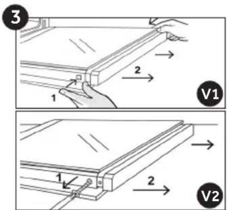
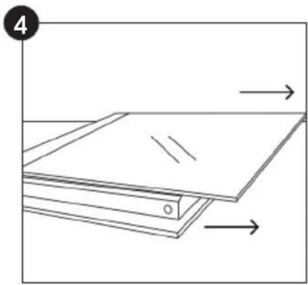
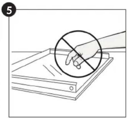
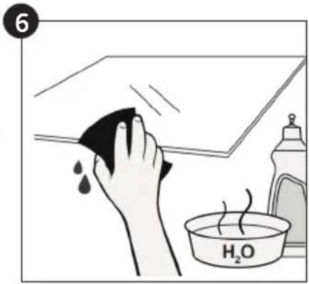
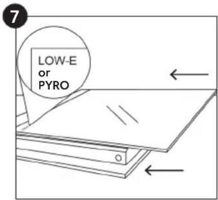
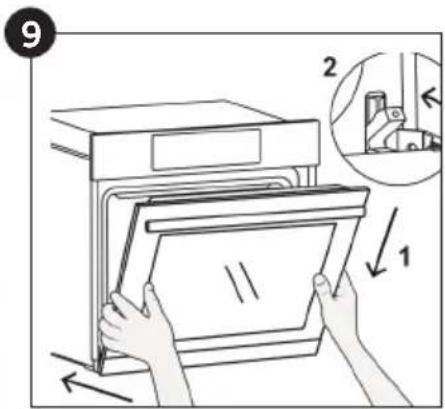
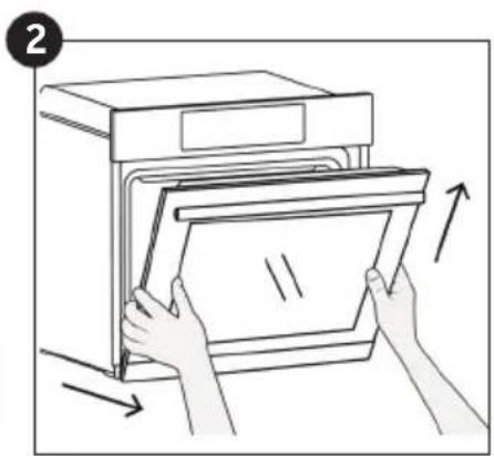
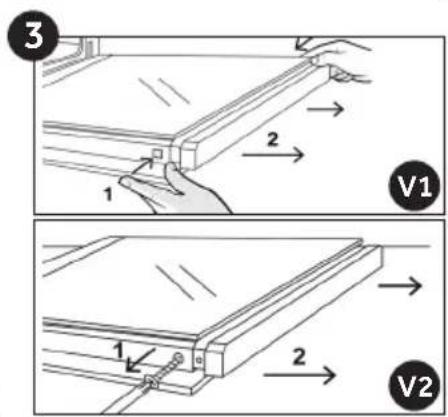
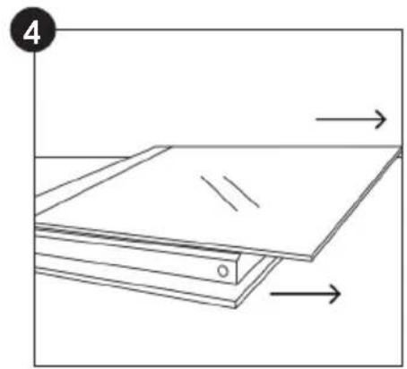
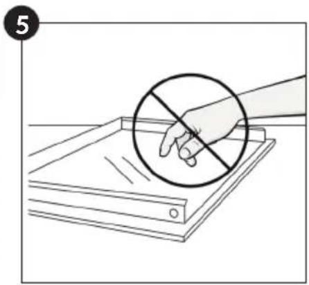
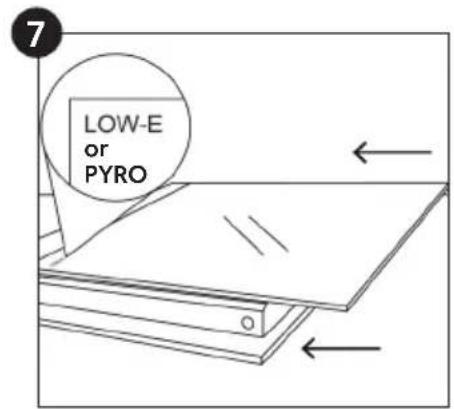
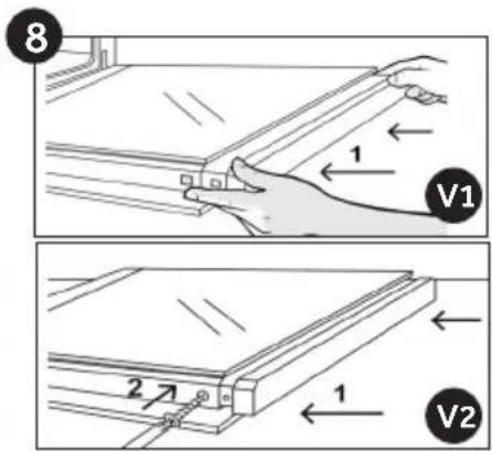
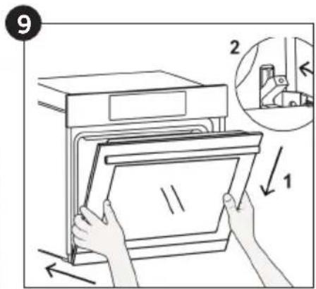
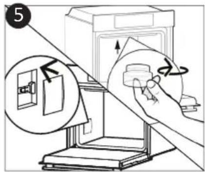
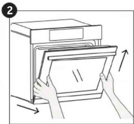
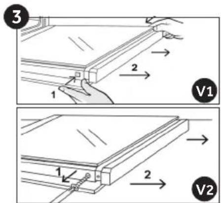
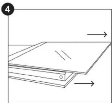
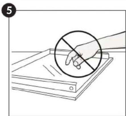
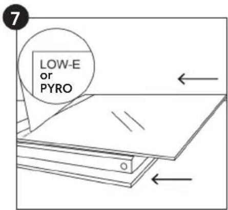
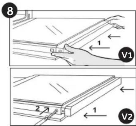
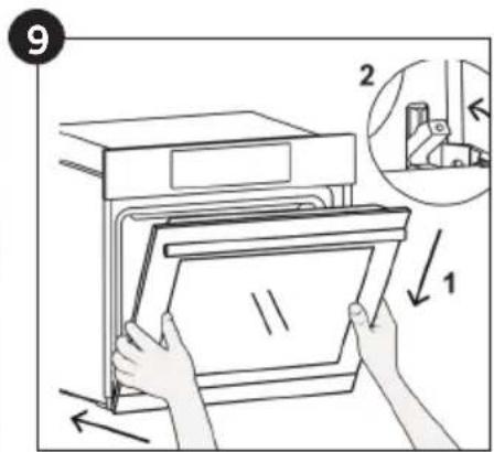
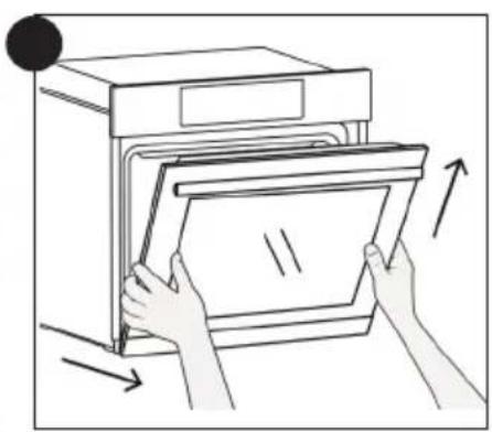
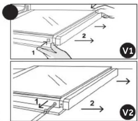
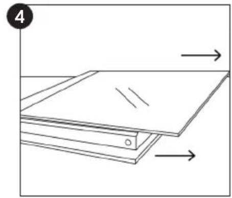
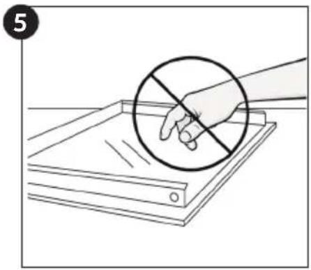
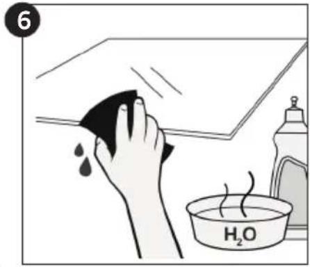
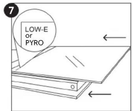
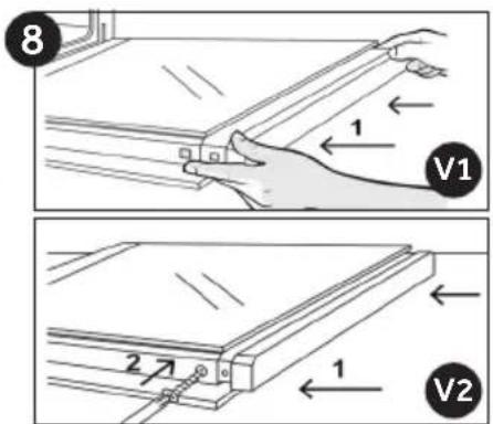
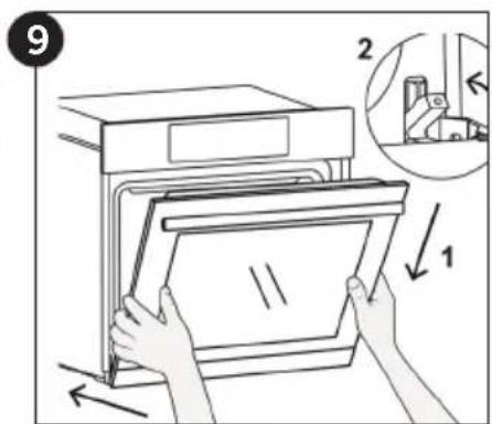
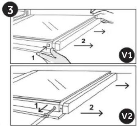
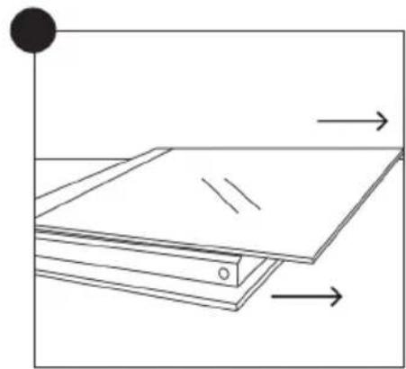
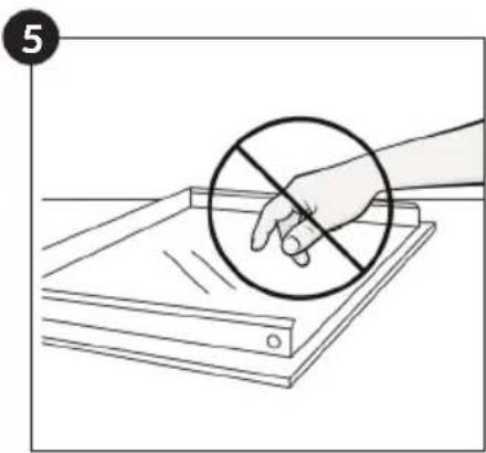
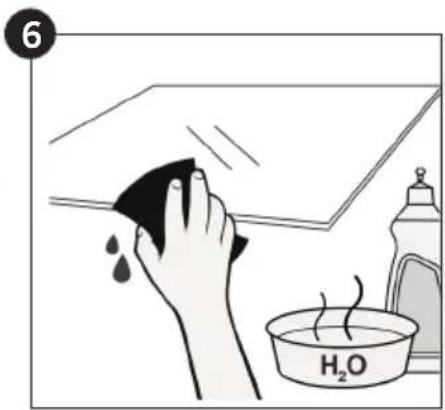
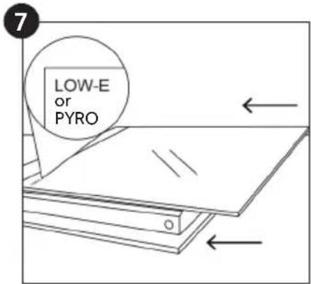
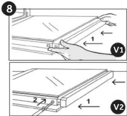
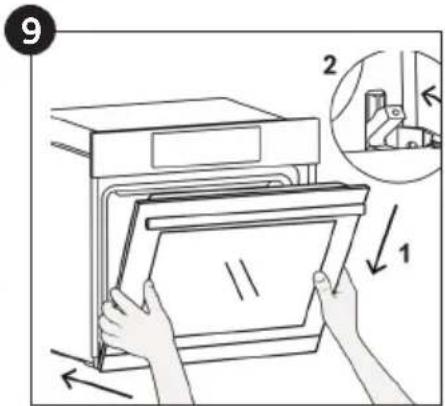
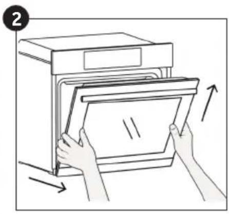
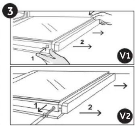
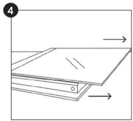
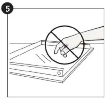
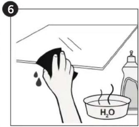
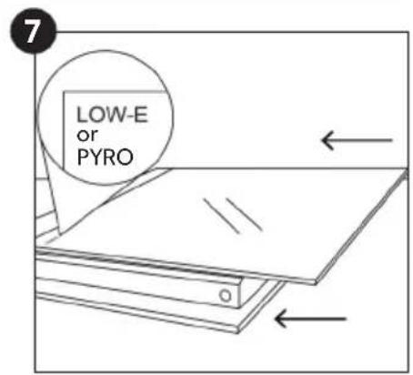
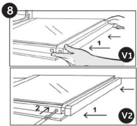
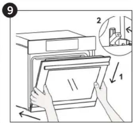
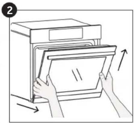
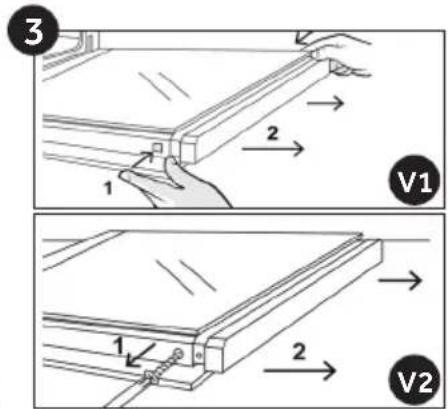
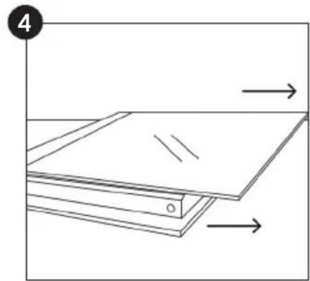
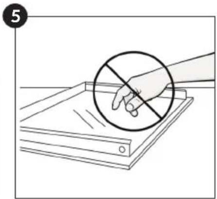
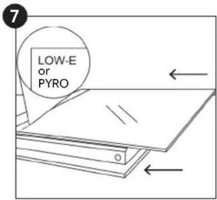
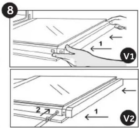
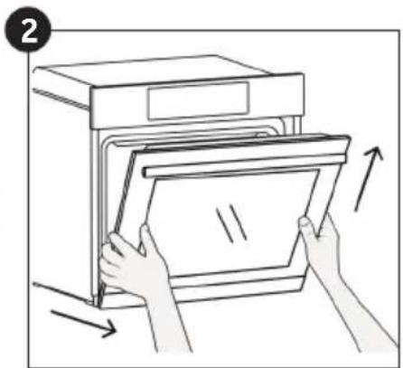
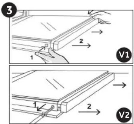
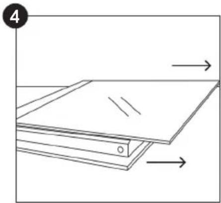
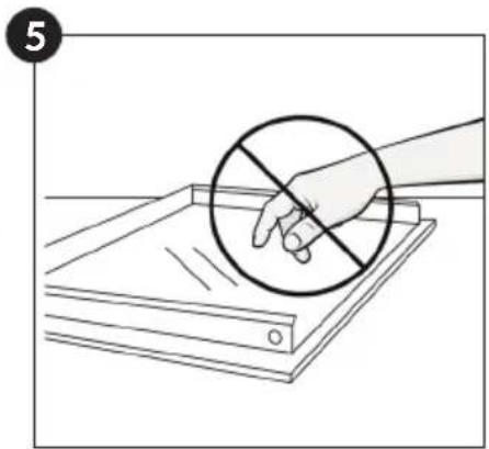
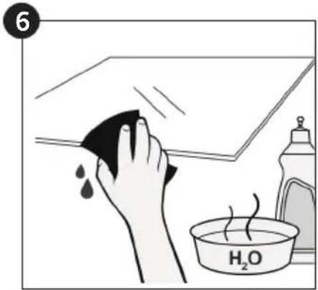
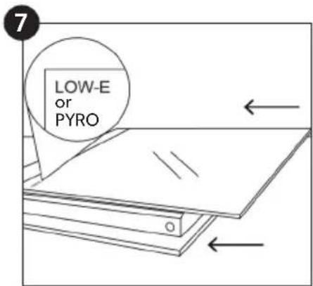
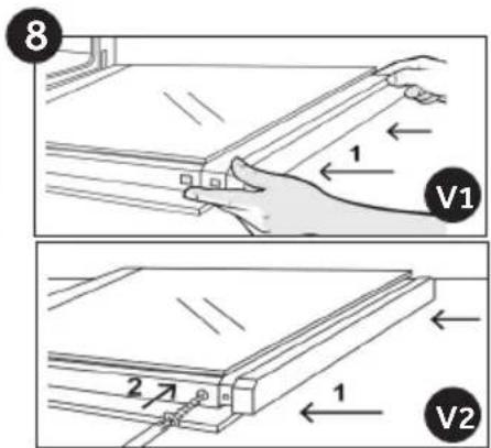
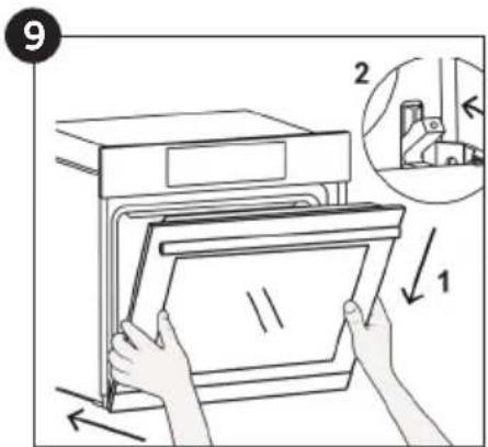
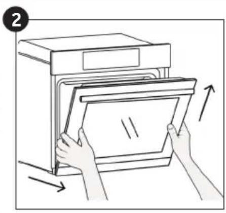
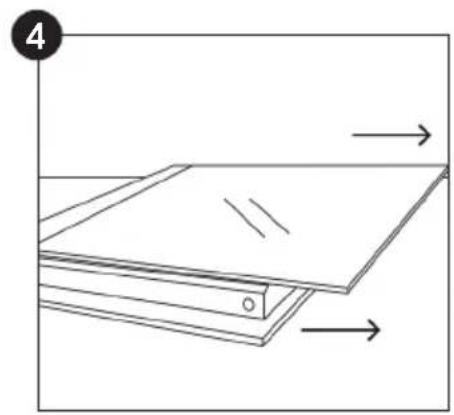
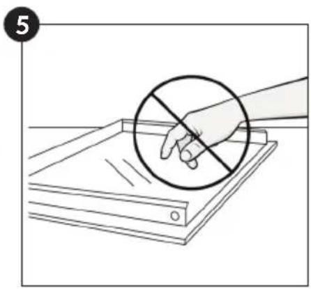
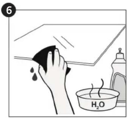
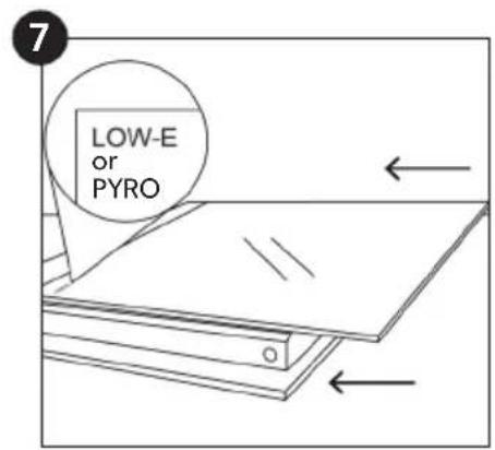
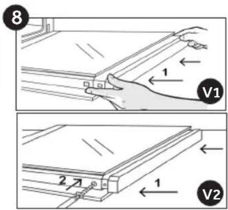
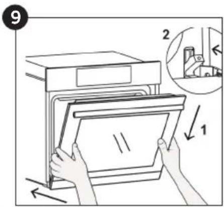
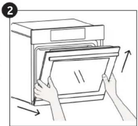
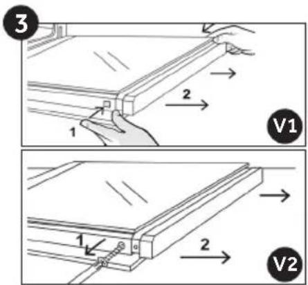
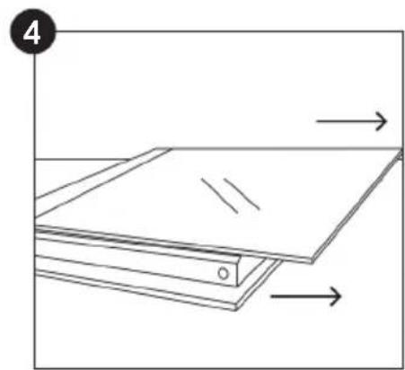
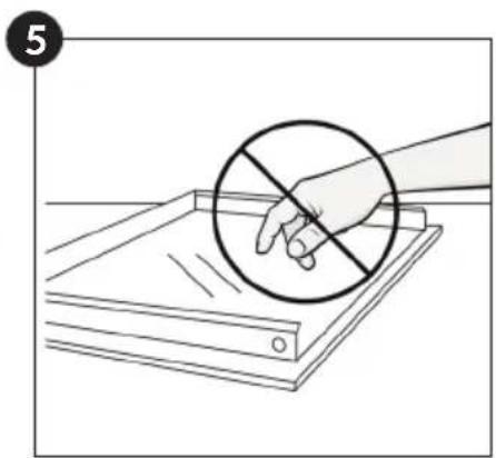
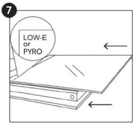
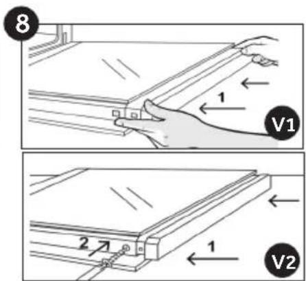
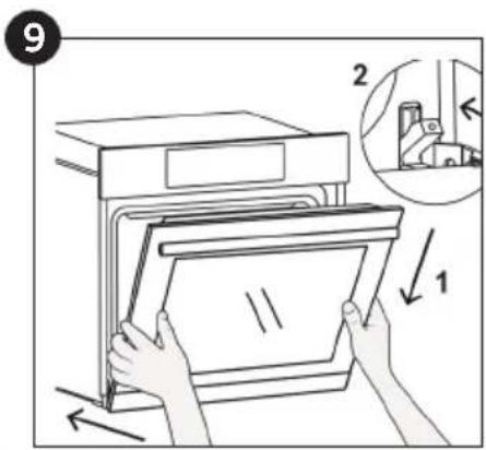
Removal and Cleaning of the Glass Door (depends on model)
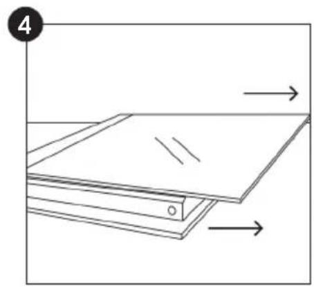
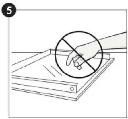
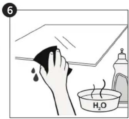
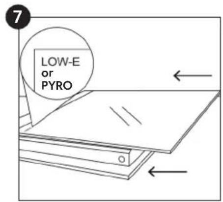

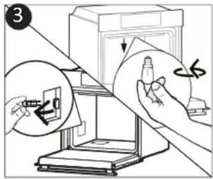
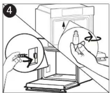
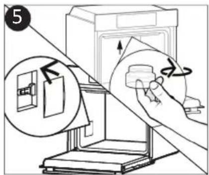
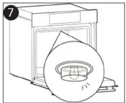
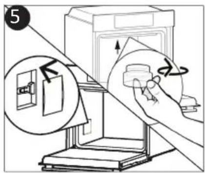
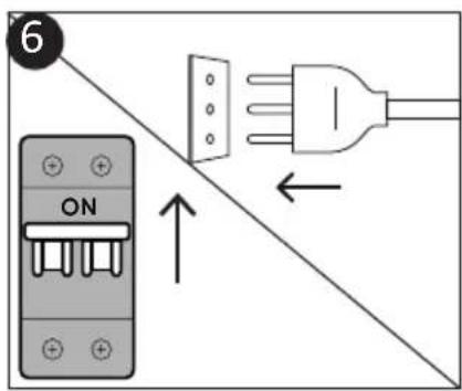
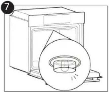
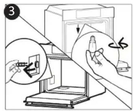
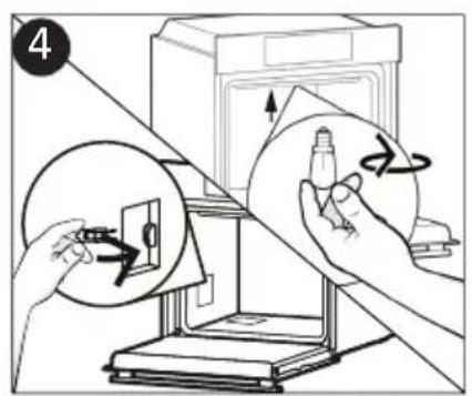
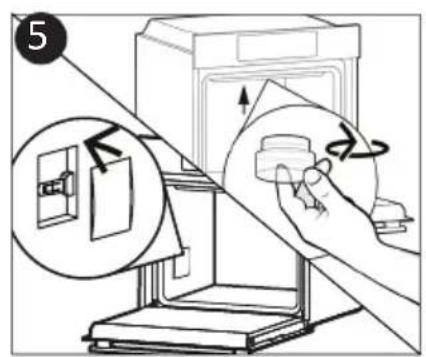
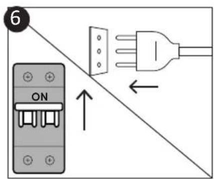
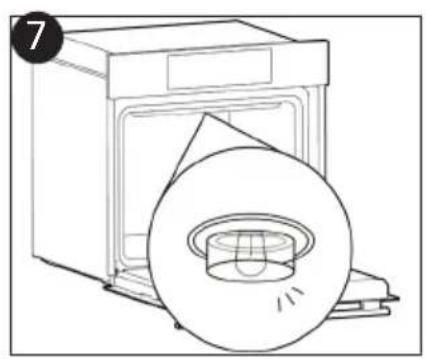
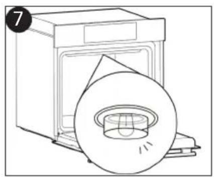
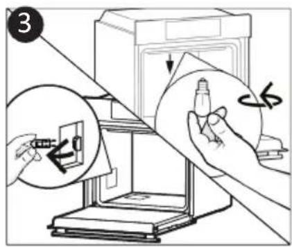
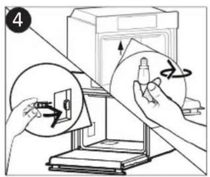
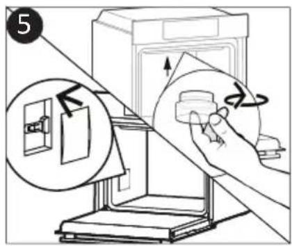
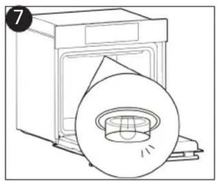
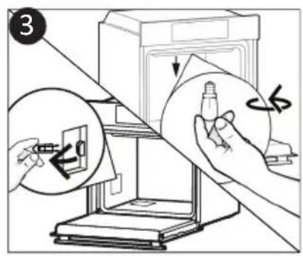
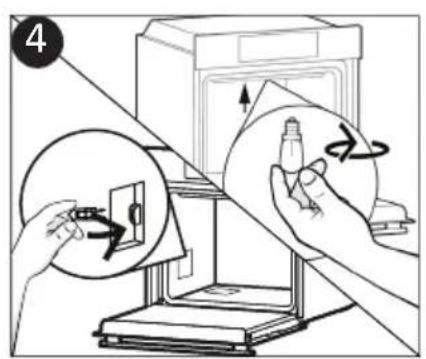
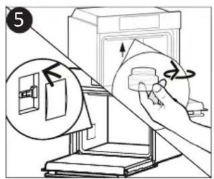
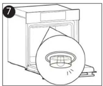
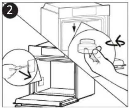
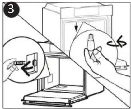
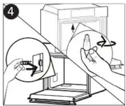
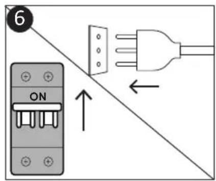
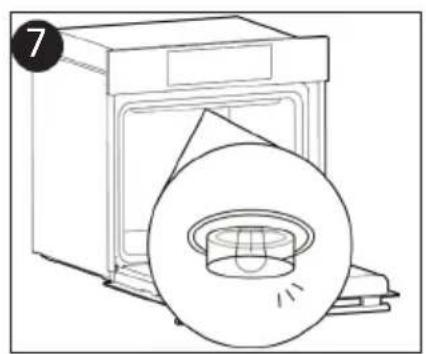
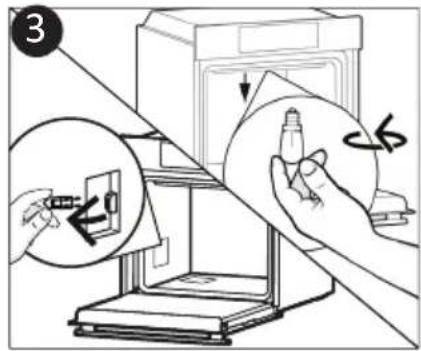
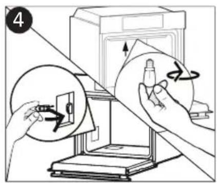
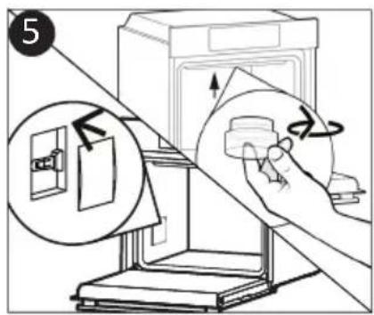
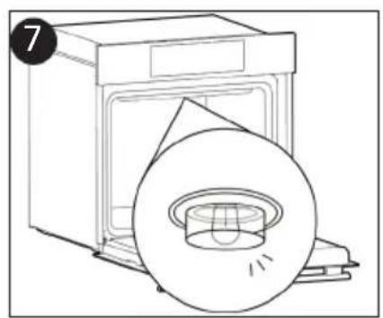
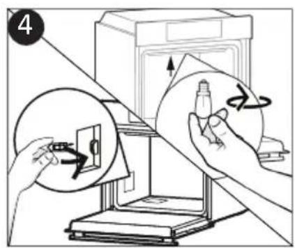
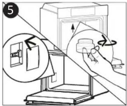
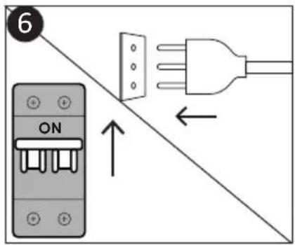
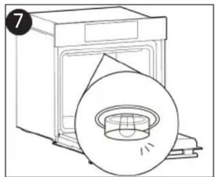
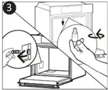
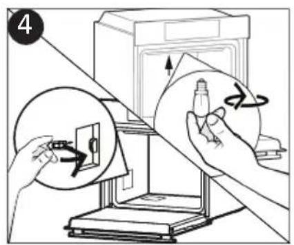
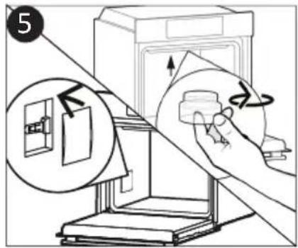
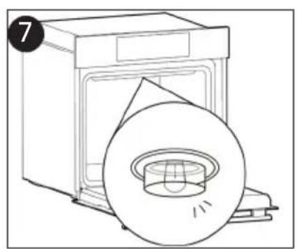
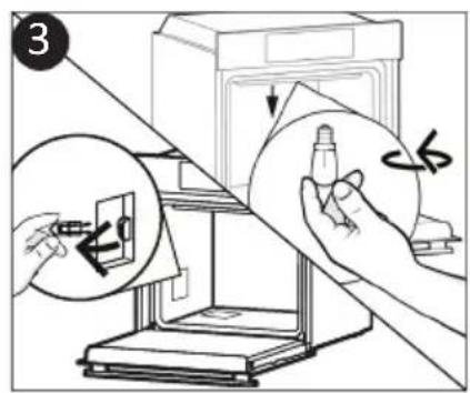
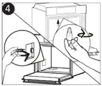
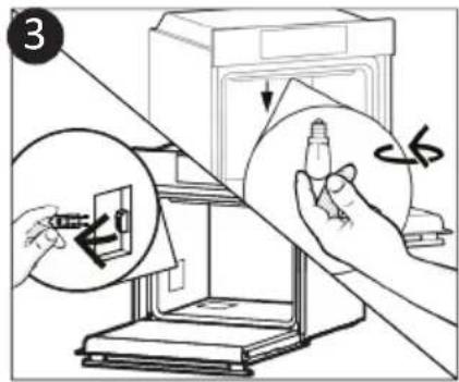
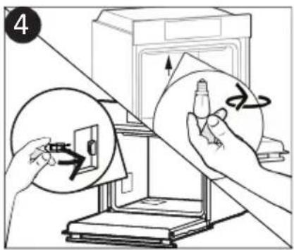
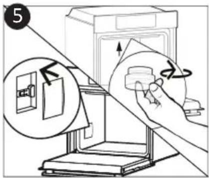
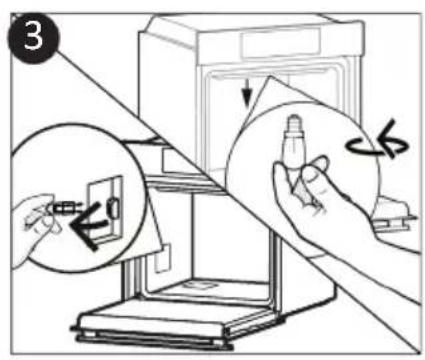
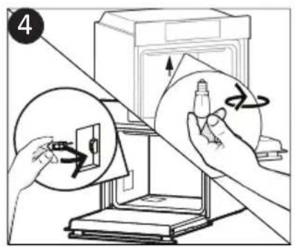
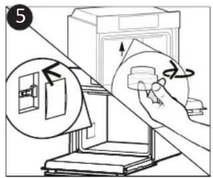
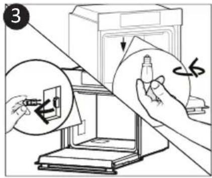
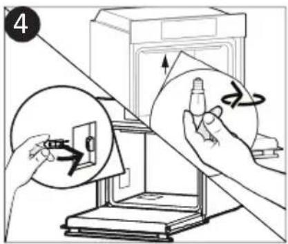
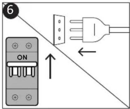
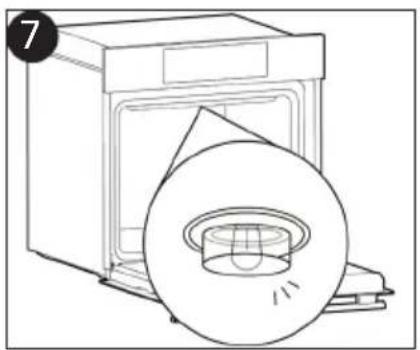
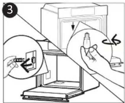
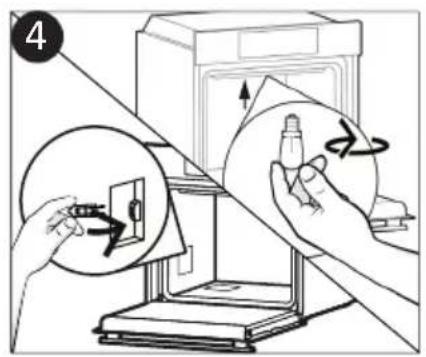
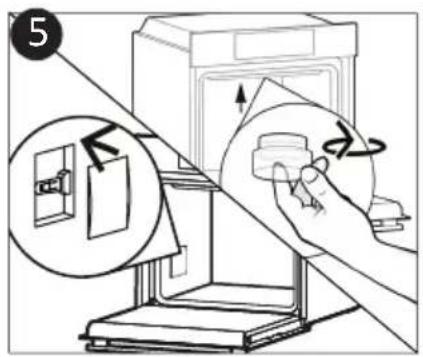
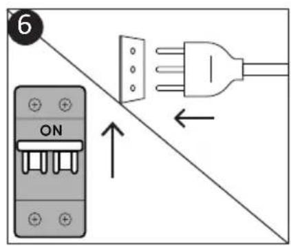
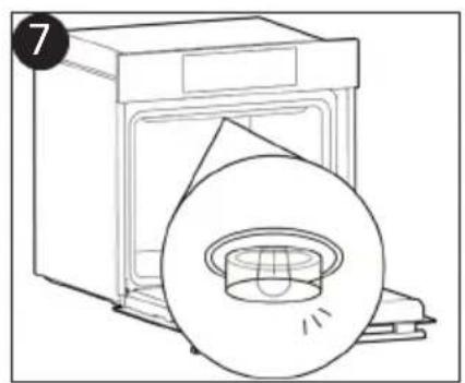
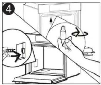
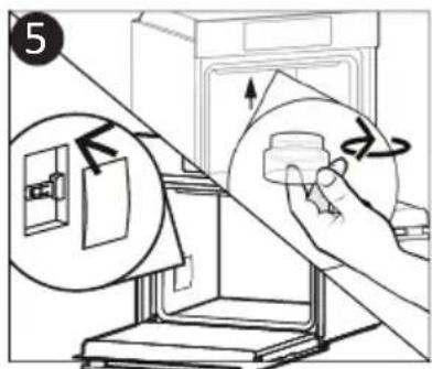
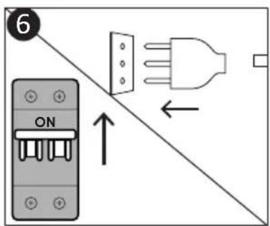
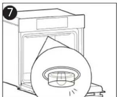
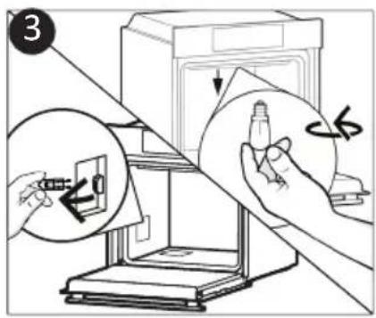
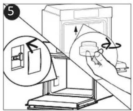
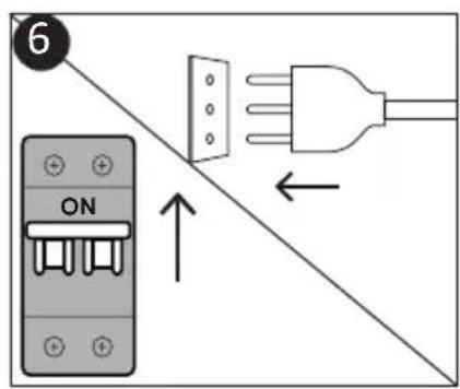
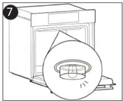
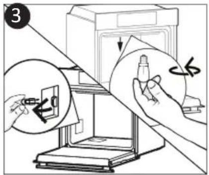
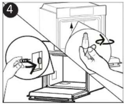
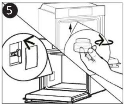
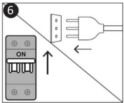
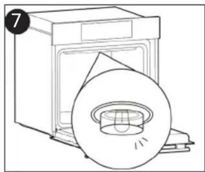
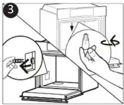
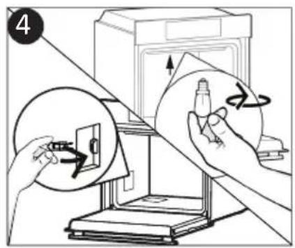
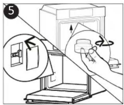
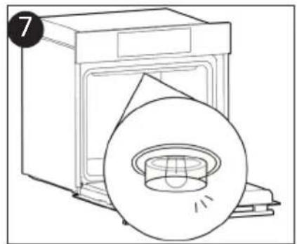
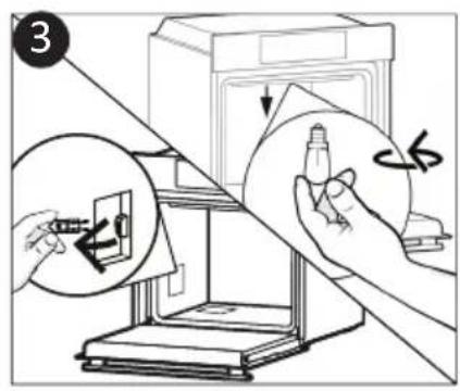
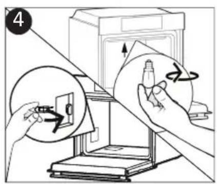
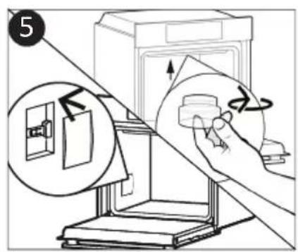
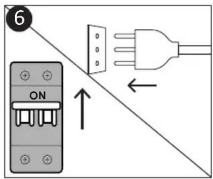
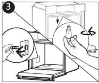
Changing the Bulb (depends on model)
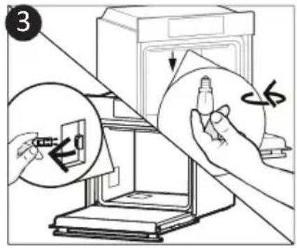
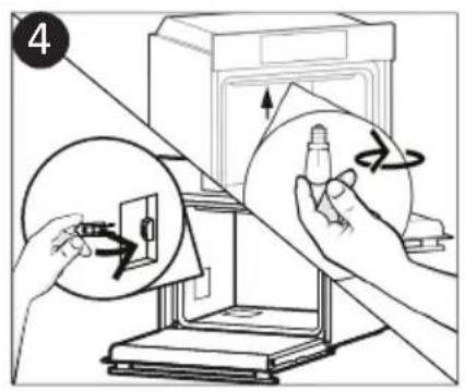
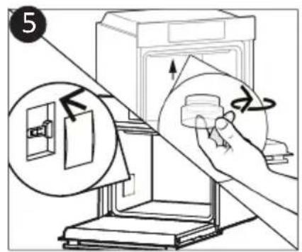
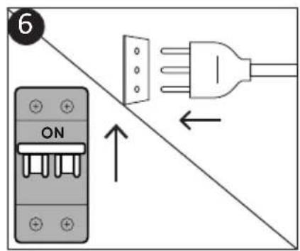
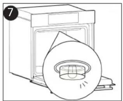
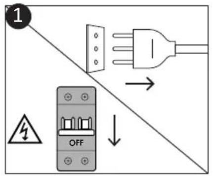
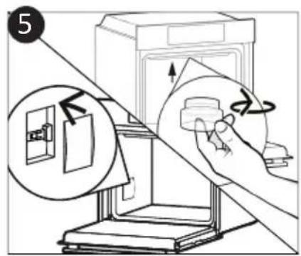
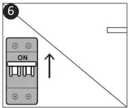
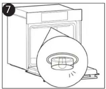
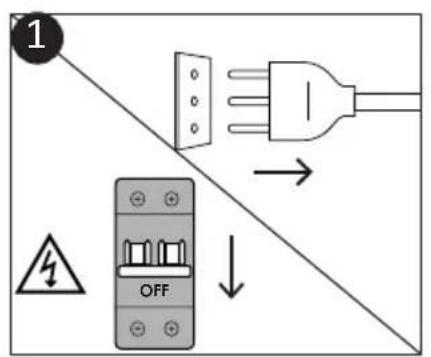
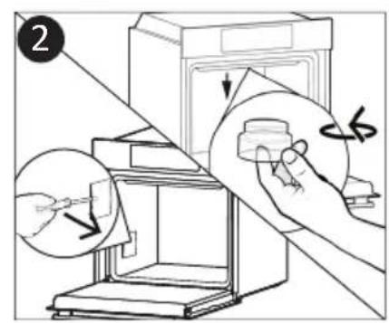
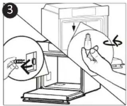
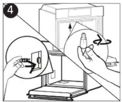
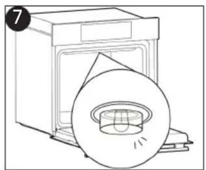
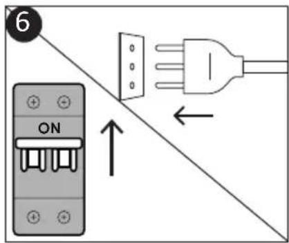
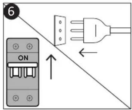
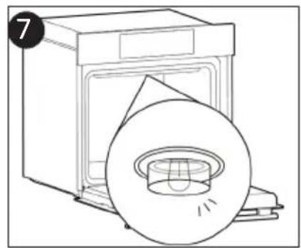
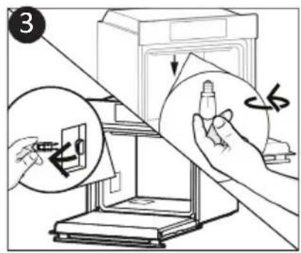
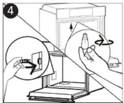
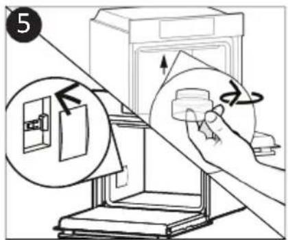
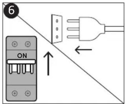
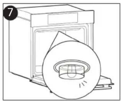
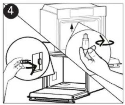
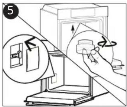
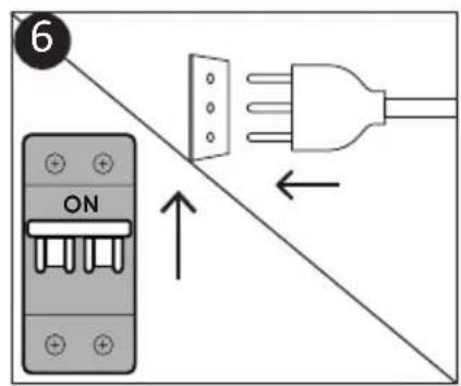
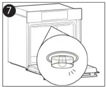
- Disconnect the oven from the mains supply.
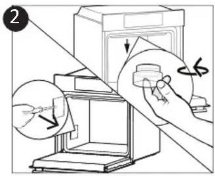
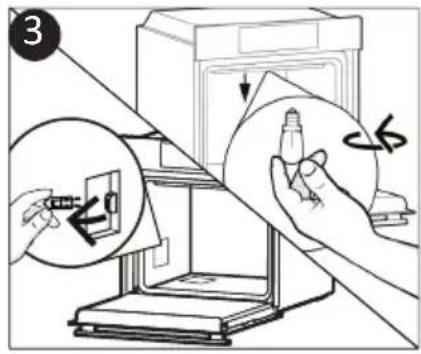
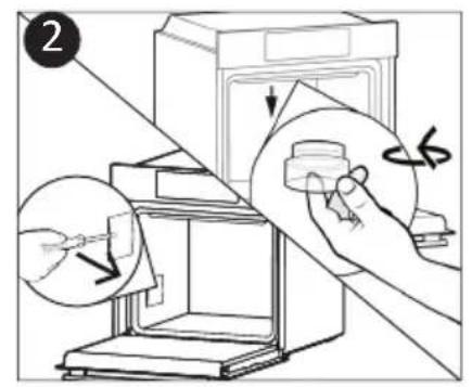
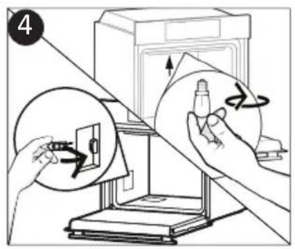
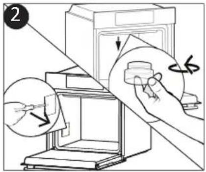
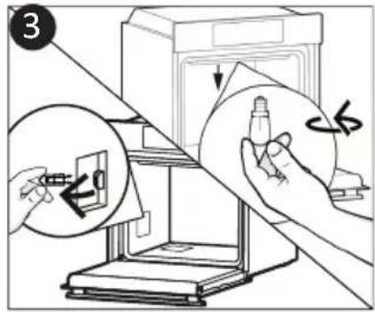
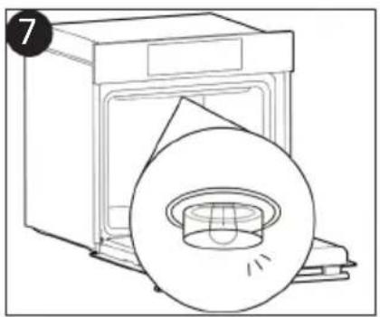
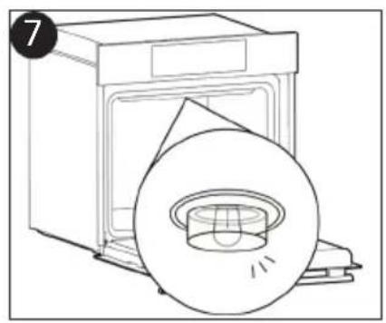
- Undo the glass cover, unscrew the bulb and replace it with a new bulb of the same type.
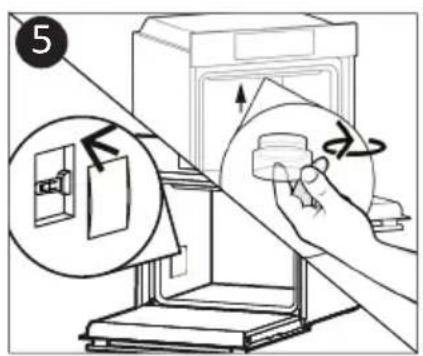
- Once the defective bulb is replaced, replace the glass cover.

This product contains one or more light sources of energy efficiency class G (Lamp) * In case of issue with this lamp, contact the customer service
Aquactiva Function (depends on model)
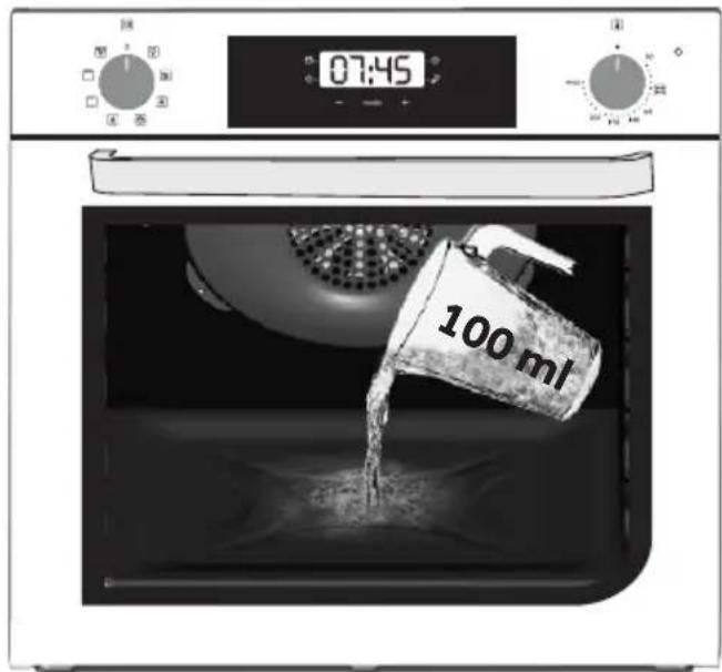
The Aquactiva procedure uses steam to help remove remaining fat and food particles from the oven.
- Pour 100 ml of water into the Aquactiva container at the bottom of the oven.
- Set the oven function to Bottom + Fan heater ( )
- Set the temperature to the Aquactiva icon
- Allow the program to operate for 20 minutes.
- After 20 minutes switch off the program and allow the oven to cool down.
- When the appliance is cool, clean the inner surfaces of the oven with a cloth.
Warning: Make sure that the appliance is cool before you touch it.
Care must be taken with all hot surfaces as there is a risk of burns.
Use distilled or drinkable water.
Waste management and environmental protection
This appliance is labelled in accordance with European Directive 2012/19/EU regarding electric and electronic appliances (WEEE). The WEEE contain both polluting substances (that can have a negative effect on the environment) and base elements (that can be reused). It is important that WEEE undergo specific treatments to correctly remove and dispose of the pollutants and recover all the materials. Individuals can play an important role in ensuring that the WEEE do not become an environmental problem; it is essential to follow a few basic rules:
- The WEEE should not be treated as domestic waste;
- The WEEE should be taken to dedicated collection areas managed by the town council or a registered company.
In many countries, domestic collections may be available for large WEEEs. When you buy a new appliance, the old one can be returned to the vendor who must accept it free of charge as a one-off, as long as the appliance is of an equivalent type and has the same functions as the purchased appliance.
SAVING AND RESPECTING THE ENVIRONMENT
Where possible, avoid pre-heating the oven and always try to fill it. Open the oven door as infrequently as possible, because heat from the cavity disperses every time it is opened. For a significant energy saving, switch off the oven between 5 and 10 minutes before the planned end of the cooking time, and use the residual heat that the oven continues to generate. Keep the seals clean and in order, to avoid any heat dispersal outside of the cavity. If you have an electric contract with an hourly tariff, the "delayed cooking" programme makes energy saving more simple, moving the cooking process to start at the reduced tariff time slot.
Troubleshooting
| Problem Possible cause Solution | |
| the oven does not heat up | The clock is not set Set the clock | |
| The oven does not heat up | A cooking function and temperature has not been set | Ensure that the necessary settings are correct |
| No reaction of the touch user interface | Steam and condensation on the user interface panel | Clean with a microfiber cloth the user interface panel to remove the condensation layer |
Installation
If the oven does not have a cooling fan, create an opening 460 mm x 15 mm.
If the furniture is covered with a bottom at the back part, provide an opening for the power supply cable.
The manufacturer will not be responsible for any inaccuracy resulting from printing or transcript errors contained in this brochure. We reserve the right to carry out modifications to products as required, including the interests of consumption, without prejudice to the characteristics relating to safety or function.
ACCESSORIES
2
1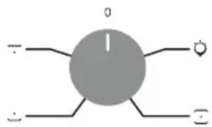
F
CANDY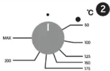
REMOVAL AND CLEANING OF THE SIDE RACKS
Special panels coated with enamel, made with a microporous structure to turn fat into gaseous elements that are easy to remove. Replace after 3 years of use (at 2/3 cooking cycles per week).
2 Steam
1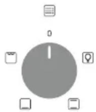
↓
2
1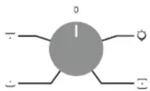
F
CANDY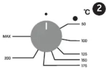
REMOVAL AND CLEANING OF THE WIRE RACKS
Use of touch control clock programmer (depends on model)
2
Steam
1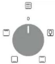
2 °C 2
1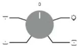
CANDY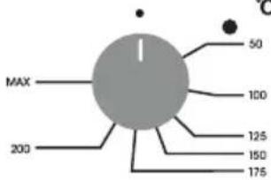
REMOVAL AND CLEANING OF THE SIDE SUPPORTS

1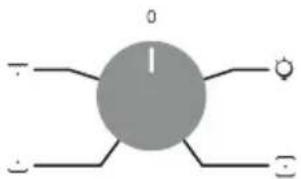
F
CANDY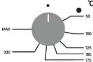
2
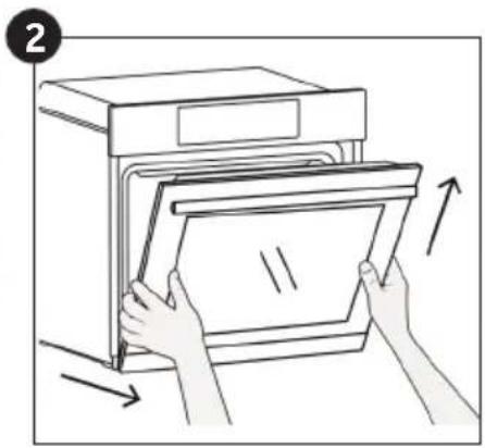
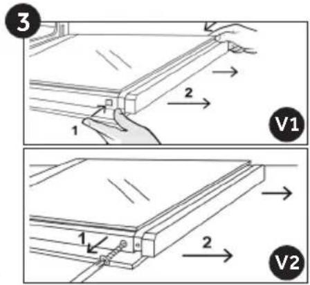
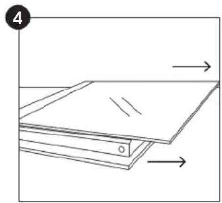
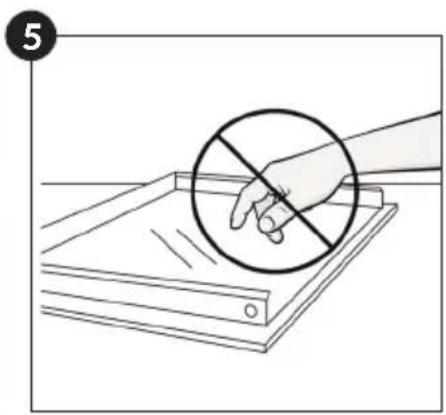
- Disconnect the oven from the mains supply.
- Undo the glass cover, unscrew the bulb and replace it with a new bulb of the same type.
- Once the defective bulb is replaced, replace the glass cover.

The airfry tray ensures that hot air reaches the food evenly and tridimensionally, resulting in a crispier exterior while maintaining tenderness inside. A baking tray can be optionally placed at L1 to collect juices or breadings.
1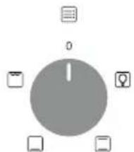
↓ 2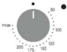
1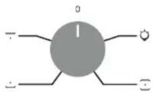
F
CANDY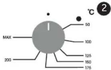
INSTRUCTIONS FOR INSTALLATION AND CLEANING OF THE LATERAL RACKS

ADDITIONAL ACCESSORIES (Depending on the oven model.)
Drip tray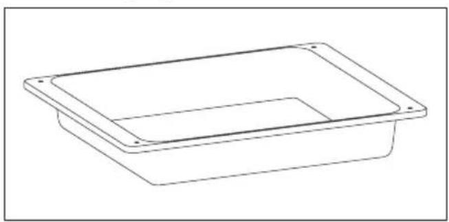
Located on both sides of the oven interior, it contains metal grids and drip trays
- Control panel
- Shelf positions (side wire rack if included)
- Grids
- Trays
- Ventilator (if present)
- Oven door
- Side wire racks (if present: only for flat interior)
- Serial number
Measures the internal temperature of food during cooking. Insert into the hole at the top of the interior. It should be placed inside while the oven is cold. WARNINGS:
- Do not heat or start cooking before properly inserting the meat probe.
- Do not attempt to insert the meat probe into frozen food.
Catalytic panels (only if present)
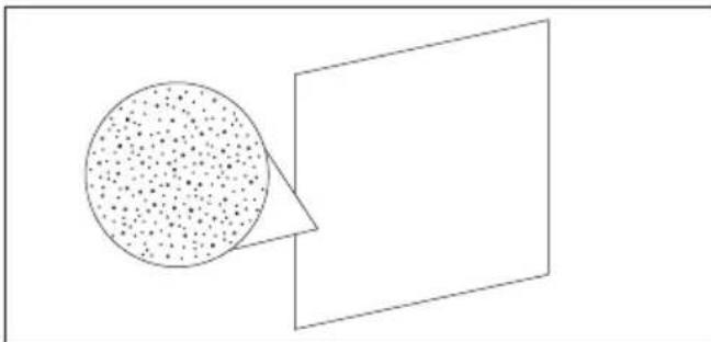
Special enamel-coated panels, made with a microporous structure to convert grease into gaseous elements that are easily removed. Replace after 3 years of use (at 2/3 cooking cycles per week).
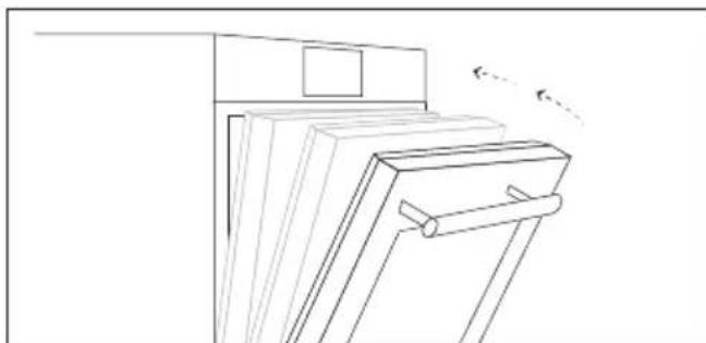
Softclose function for gentle closing (only if present)
Air conveyor that increases air circulation around the oven. This allows for improved baking performance, more even cooking of food at all temperatures, shorter baking times, and ultimately, an even distribution of temperature inside the oven.
Airfry rack (only if present)
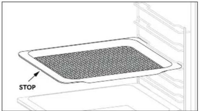
The air frying tray ensures that hot air reaches the food evenly and three-dimensionally, resulting in a crispy exterior while the interior remains juicy and tender. Optionally, the baking tray can be placed on level L1 to collect juices or crumbs.
Description of the control panel (Depending on the oven model.)
Information on low energy consumption in accordance with Commission Regulation (EU) 2023/826
Energy consumption of the product in standby mode with information or status display: 0.8 W
Period after which the equipment automatically reaches standby mode with information or status display: 20 min
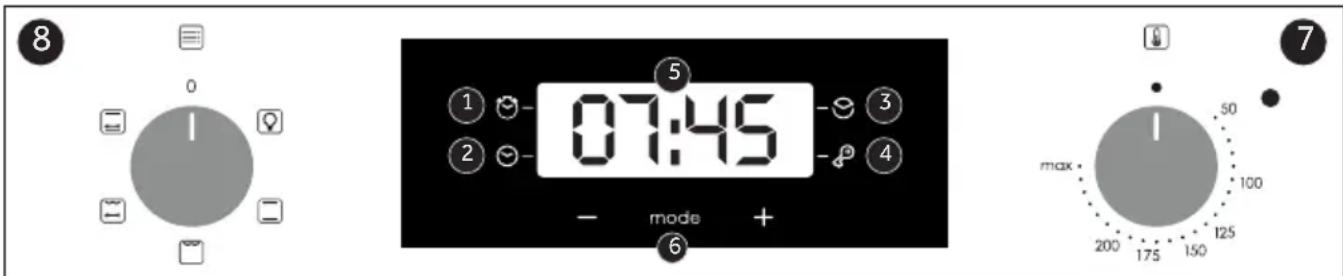
- Minutes
- Clock setting
- Cooking time
- Child lock
- Temperature or clock display
- Controls for adjusting the LCD screen
- Function selection button
- Thermostat selection button
WARNING: the first operation to be performed after the oven is installed or after a power failure (this is recognizable on the display which pulses and shows 12:00) sets the exact time. This is done as follows.
• Press the central button. - Set the time using the "-" "+" buttons. - Release all buttons.
2
1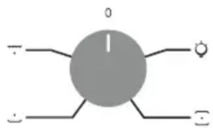
F
CANDY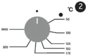
Information on low energy consumption in accordance with Commission Regulation (EU) 2023/826
Power consumption of the product in off-mode: 0.5 W
Time after which the equipment automatically reaches the off-mode state: 20 min.
REMOVAL AND CLEANING OF SIDE RACKS
- Remove the wire racks by pulling them in the direction of the arrows (see below).
- To clean the wire racks, place them in the dishwasher or clean them with a damp sponge, and then be sure to dry them.
- After cleaning, put the wire racks back into the oven in reverse order.
Removal and Cleaning of the Glass Door (Depending on the oven model.)
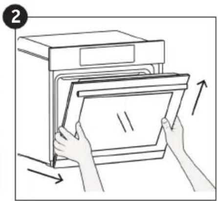
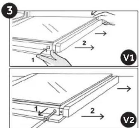
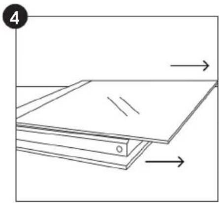

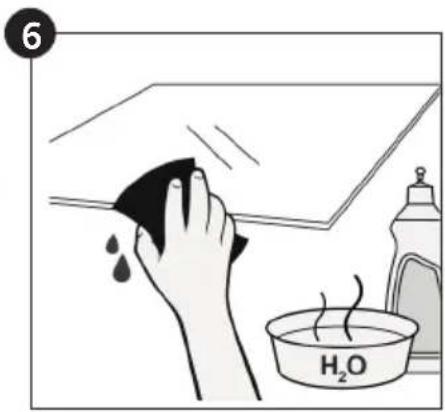
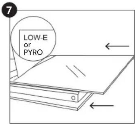
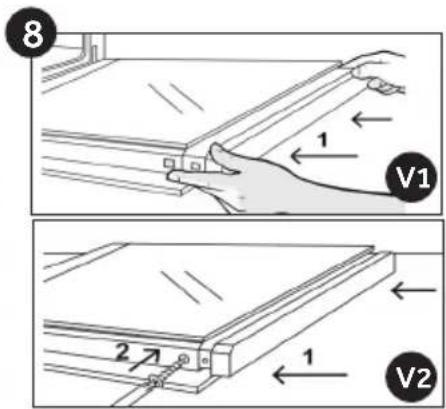
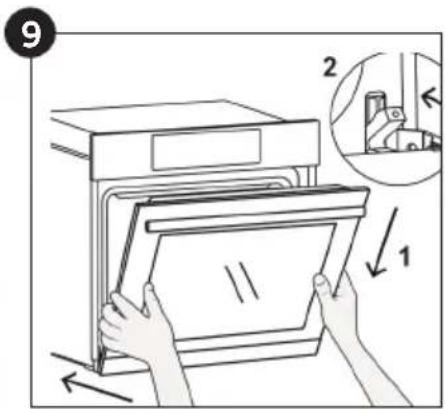
Replacing the Light Bulb (Depending on the oven model.)
- Disconnect the oven from the mains power supply.
- Remove the glass cover, unscrew the bulb, and replace it with a new bulb of the same type.
- After replacing the faulty bulb, put the glass cover back in place.
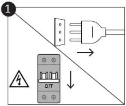

This appliance is marked in accordance with the European Directive 2012/19/EU regarding waste electrical and electronic equipment (WEEE). WEEE contains polluting substances (which can have a negative impact on the environment) as well as base elements (which can be reused). It is important that WEEE waste undergoes specific treatment in order to properly remove pollutants and recover useful materials. Every individual can play an extremely
important role in ensuring that WEEE does not become an environmental problem. It is necessary to follow the basic rules:
- WEEE cannot be considered municipal waste;
- WEEE must be taken to appropriate collection points controlled by recycling facilities. In many countries, it is possible to arrange for such waste to be collected directly from home addresses. When you purchase a new appliance, some retailers may arrange for the old one to be taken away, as long as it is of the same type as the new appliance purchased.
SAVING AND RESPECTING THE ENVIRONMENT
Where possible, avoid preheating the oven and always try to fill it as much as possible. Open the oven door as infrequently as possible, because a large amount of heat escapes each time it is opened. For significant energy savings, turn off the oven 5 or 10 minutes before you plan to finish the baking time, thereby using the residual heat that the oven continues to generate. Keep all gaskets clean and in place, to avoid any loss of heat and energy.
Troubleshooting
| Problem Mogući Razlog Rešenje | |
| Rerna ne greje Sat nije podešen. Podesite tačno vreme. | |
| Rerna ne greje Zaštita ekrana je aktivna. Deaktivirajte blokadu. | |
| Rerna ne greje | Funkcija ili temperatura nisu dobro podešene. | Pobrinite se da je rerna pravilno podešena. |
Installation
EN If the oven does not have a cooling fan, make an opening of 460 mm x 15 mm.
DEMONTAGE AND CLEANING OF SIDE RACKS


2 Steam
1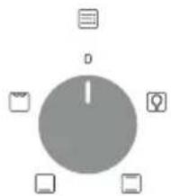
2
1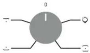
F
CANDY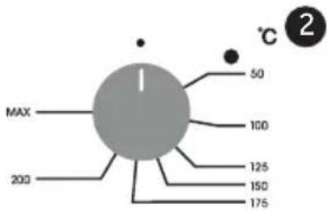
Information on low energy consumption according to Commission Regulation (EU) 2023/826
Power consumption of the product in off mode: 0.5 W
REMOVAL AND CLEANING OF SIDE GRILLS
- Disconnect the oven from the mains supply.
- Undo the glass cover, unscrew the bulb and replace it with a new bulb of the same type.
- Once the defective bulb is replaced, replace the glass cover.
ADDITIONAL NOTES (Depending on the oven model.)
The oven grills are not suitable for direct contact with food. Please use appropriate baking trays or baking paper.
Telescopic guides (only if present)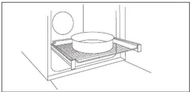
It measures the internal temperature of the food during cooking. Insert it into the hole at the top of the baking compartment. Insert it while the oven is cold. WARNINGS:
- Do not heat the oven or start cooking until the meat probe is correctly inserted.
- Do not attempt to insert the meat probe into frozen food.
For rotisserie cooking, preheating is not necessary. Cooking is done with the door closed.
REMOVAL AND CLEANING OF SIDE SUPPORTS
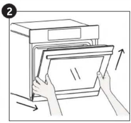
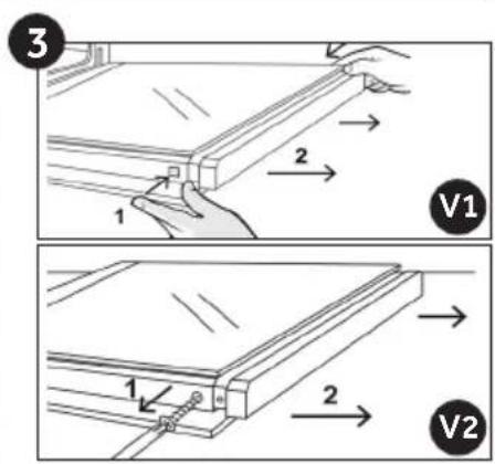
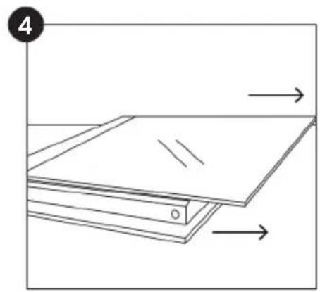
Replacing the light bulb (Depending on the oven model.)
2 Steam
1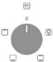
2
2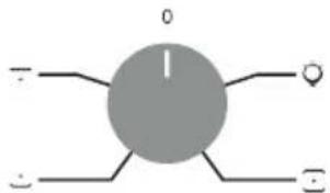
They are located on both sides of the oven and hold the metal grids and trays for collecting juices.
- Control panel
- Shelf positions (side wire rack if included)
- Grids
- Plitice
- Ventilator (if present)
- Oven door
- Side wire racks (if present: only for flat cavity)
- Serial number
A simple shelf can accommodate molds and containers.
The tray holder shelf is especially good for grilling.
Use it with the tray to collect liquids.
Changing the light bulb (depends on model)
- Disconnect the oven from the power supply.
- Remove the glass cover, unscrew the bulb, and replace it with a new bulb of the same type.
- After replacing the faulty bulb, put the glass cover back.

This product contains one or more light sources whose energy efficiency class is G (Lamp)* In case of problems with this lamp, contact customer service
Aquactiva function (depends on model)
The Aquactiva procedure uses steam to remove grease and other residues from the oven.
- Pour 100 ml of water into the "Aquactiva" reservoir at the bottom of the oven.
- Set the oven function to Bottom heat + Fan ( )
- Set the function selector knob to the "Aquactiva" symbol.
- Let the program run for 20 minutes.
- After 20 minutes, switch off the program and let the oven cool down.
- When the appliance has cooled down, clean the interior surfaces of the oven with a cloth.
WARNING:
Before wiping the interior surfaces, make sure the oven is completely cool. Be careful and pay special attention to any hot surfaces, as there is a risk of burns.

Hinges that ensure automatic soft and smooth movement during the closing phase of the oven door.

REMOVAL AND CLEANING OF THE SIDE RACKS

ACCESSORIES (depending on model)
2 Steam
1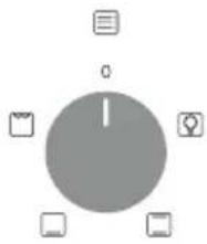
2
1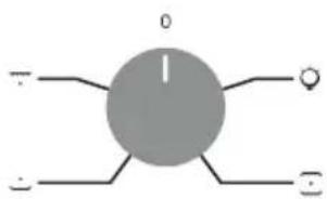
F
CANDY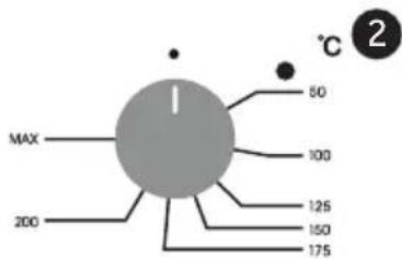
REMOVAL AND CLEANING OF THE SIDE GUIDES

ACCESSORIES (depending on model)
REMOVAL AND CLEANING OF THE SIDE RACKS
ACCESSORIES (depending on model)
CANDY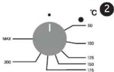
REMOVAL AND CLEANING OF THE SIDE RACKS

DRIP TRAY (depending on model)
Collect any drippings that fall while food is being cooked on the grill.
Located on both sides of the oven cavity and supports metal grill racks and drip pans.
Metal rack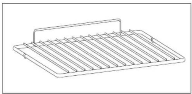
INSTRUCTIONS FOR REMOVING AND CLEANING THE SIDE HOLDERS
INSTRUCTIONS FOR REMOVING AND CLEANING THE SIDE HOLDERS

- Control panel
- Placement of shelves (end grid if included)
- Racks
- Drawers
- Fan (if present)
- Oven door
- Lateral wire rack (if present: only for flat cavity)
8. Serial number
Write the serial number here for future reference.
ACCESSORIES (depends on model)
Drip tray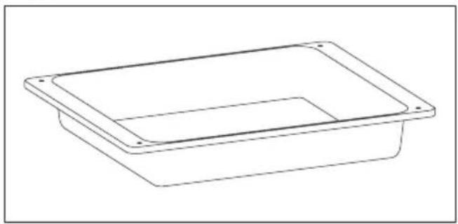
Hinge that ensures a soft and even automatic movement during the closing phase of the oven door.
No preheating is necessary for rotisserie cooking. Cooking with the door closed.
INSTRUCTIONS FOR REMOVING AND CLEANING THE SIDE RACKS
This product contains one or more light sources with energy efficiency class G (Lamp) * If there are problems with this lamp, contact customer service
REMOVAL AND CLEANING OF THE SIDE RACKS