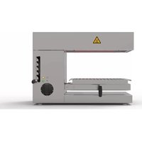
SAE641 - Oven MBM - Free user manual and instructions
Find the device manual for free SAE641 MBM in PDF.


| Product type | Professional cooking oven |
| Brand | MBM |
| Model | SAE641 |
| Weight | 49 kg |
| Power supply | 220-240 V ~ 50/60 Hz, 4 kW |
| Protection rating | IPX3 |
| Use | Commercial, qualified personnel |
| Main functions | Cooking with timer, power adjustment (positions 1-6 and ∞), end-of-cycle beep |
| Specific models | SE_40, SE_60, SE80, SEL_, QSE_, QSET_ (depending on version) |
| Controls | Rotary knob, start/stop buttons, digital display of remaining time |
| Safety | Emergency stop, overcurrent protection (fuse on QSE_ models), mandatory grounding, equipotential system |
| Maintenance and cleaning | Daily cleaning of the tray with soapy water; for ceramic glass (QSE_ models), mild detergent and cloth |
| Installation | On worktop or wall mounting, minimum distance of 300 mm from sides and 100 mm from rear |
| Max ambient temperature | 50 °C around the appliance |
| Plate material (QSE_) | Ceramic glass |
| Included accessories | Power cable, trays, wall mounting bracket (optional) |
| Repairability | Annual maintenance recommended by approved service; spare parts available via after-sales service |
| Ecology | Recyclable packaging, appliance to be recycled at end of life after removing the cable |
Frequently Asked Questions - SAE641 MBM
User questions about SAE641 MBM
0 question about this device. Answer the ones you know or ask your own.
Ask a new question about this device
Download the instructions for your Oven in PDF format for free! Find your manual SAE641 - MBM and take your electronic device back in hand. On this page are published all the documents necessary for the use of your device. SAE641 by MBM.
USER MANUAL SAE641 MBM
natural_image
Technical line drawing of a multi-level industrial enclosure with internal components and ventilation ducts (no text or symbols)ACCENSIONE, USO E SPEGNIMENTO QSE\_
Modello QSE_40
flowchart
graph TD
    subgraph Timer
        X["Start"] --> 9900
        C["Start"] --> START
        STOP["Stop"] --> D["Output"]
    end
    Timer --> Y["Output"]
    Timer --> Z["Output"]
    Timer --> Y
    Timer --> Z
    Timer --> Y
    Timer --> Z
    Timer --> Y
    Timer --> Z
    Timer --> Y
    Timer --> Z
    Timer --> Y
    Timer --> Z
    Timer --> Y
    Timer --> Z
    Timer --> Y
    Timer --> Z
    Timer --> Y
    Timer --> Z
    Timer --> Y
    Timer --> Z
    Timer --> Y
    Timer --> Z
    Timer --> Y
    Timer --> Z
Modello QSE\_60
ACCENSIONE, USO E SPEGNIMENTO SEL\_
⚠ The appliance referred to in this manual has been manufactured in conformity with the European Directives on "Low Voltage" and "Electromagnetic Compatibility".
This appliance has been designed exclusively for cooking food; any other use is considered improper. It should only be used by qualified personnel, duly instructed, and only for the purpose for which it was designed.
⚠ The appliance must be installed, connected and serviced properly by qualified personnel according to the regulations and directives in force in the country where it is installed, as well as the instructions in this manual. The appliance should be checked once a year by a qualified technician.
natural_image
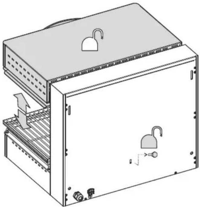
Technical line drawing of a multi-level industrial enclosure with internal components and ventilation ducts (no text or symbols)⚠ For models _SE_40, _SE_60 and SE80 only, before positioning and using the equipment, remove the screw on the back; for subsequent transportation, reposition the shelf locking screw.
⚠ Position the equipment at a height compatible with your own height avoiding incorrect posture and excessive strain.
⚠ Do not place any material that could block the air intakes on the side and bottom.
⚠ Do not put your fingers in the slots; there is a risk of crushing.
⚠️ Do not release the handle quickly; there is a risk of crushing.
⚠ Do not open the dashboard and touch the electrical components. Contact the technical support service
When using the equipment, wear gloves for cooking and clothing that covers the entire body.
⚠️ Switch the appliance off in the case of a failure or malfunction.
⚠ The basin must always be inserted when the appliance is in operation.
⚠️ Be careful when using the appliance because the cooking surfaces become very hot.
⚠️ Be careful and contact the technical support service if any parts or components come loose.
⚠️ Make sure that the maximum temperature of the cooking area is compatible with the food being cooked.
⚠️ If the appliance must be positioned near walls, partitions, kitchen furniture, etc., we recommend that these are made
of non-combustible materials; failing this, they must be covered with non-combustible heat insulating materials.
⚠️ If the appliance is mounted on the wall, use the appropriate brackets to be requested as an optional. Do not place it on top of other heat-distributing equipment (fry tops, fryers, open fires, etc.).
⚠️ Check that the wall is masonry, made of non-flammable material and that it can hold a weight of 60 kg.
The brackets to be fixed to the wall are to be applied by making holes in the wall according to the drilling drawing shown on the installation diagram in the booklet; use 4 steel anchors suitable for M6 screws.
INSTALLATION AND CONNECTION TO THE POWER SUPPLY
The manufacturer declines any liability for damage caused by improper or incorrect installation or maintenance of the appliance, or failure to observe safety regulations.
Remove the appliance packaging as well as the protective plastic sheet. If necessary, remove any glue with a suitable solvent. Dispose of the packaging according to local regulations (for more details refer to the chapter "ECOLOGY AND THE ENVIRONMENT").
When installing the appliance, all the regulations in force must be observed, such as:
■ Applicable national laws in force;
■ Regional and/or local regulations, such as building regulations;
■ Directives and regulations stipulated by the local electricity supplier;
■ Accident prevention regulations in force;
■ Fire prevention regulations;
The appliance should be installed under an extractor hood so that cooking fumes can be removed. The equipment can be placed on a work surface or installed on a wall. The distance from adjacent equipment or from flammable surfaces must be at least 300 mm from the sides and 100 mm from the rear wall. The appliance, and more specifically, the power cord, must not be positioned near heat sources; the temperature in the area surrounding the appliance must not exceed 50°C.
Before proceeding with the connection, compare the appliance data (the technical data can be found on the ratings plate on the rear panel of the appliance) with power delivery on site.
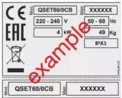
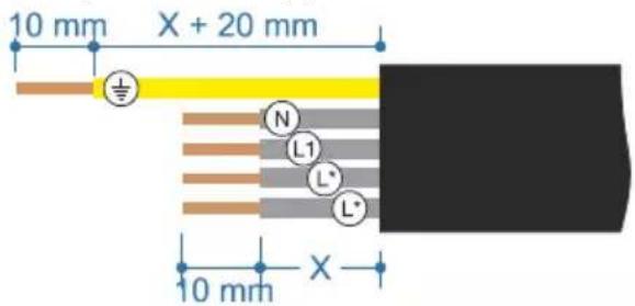
The appliance is supplied with a power cord; the installer must connect it after interposing the main power supply cut-off switch. The opening contacts must be minimum 3 mm apart per pole. The cut-off device must be easily accessible.
⚠️ If the power cord must be replaced, following the instructions in the wiring diagram attached to this manual.
The power cord must not have characteristics lower than H07 RN-F and must have a minimum cross-section as indicated on the cover. The appliance must be connected to an effective earth socket. There is a connection on the terminal board for this purpose that is identified by the symbol to which the earth conductor is to be connected. Furthermore, the appliance must be included in an equipotential system. The connection is made to a specific terminal, marked with the symbol , on the back panel of the appliance.
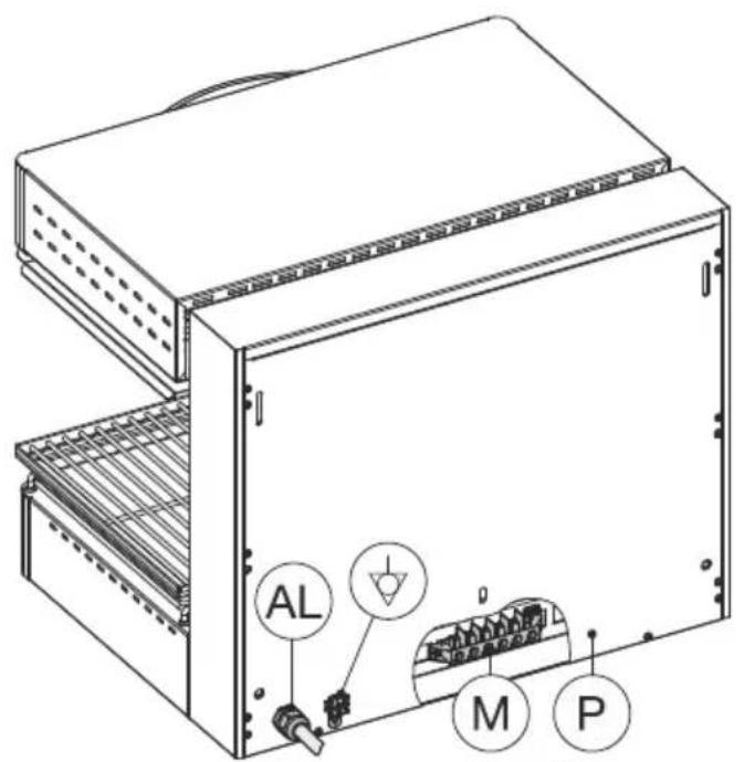
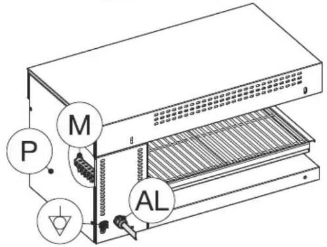
To access the terminal board "M" remove the panel "P" on the back (_SE_40, _SE_60 and SE_80) or side (SEL_); disconnect the wires from the terminal board, loosen the cable gland "AL" and replace the cable in reverse order.
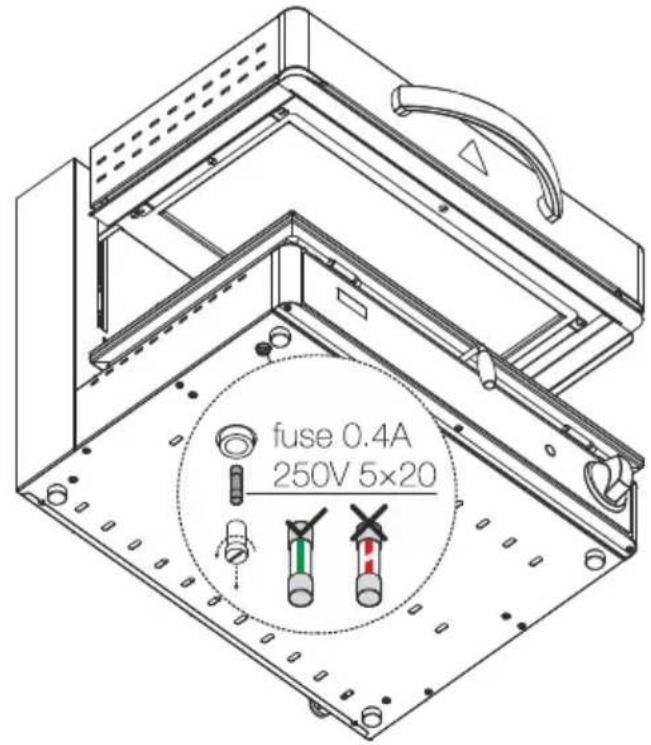
The "QSE_" models are equipped with a fuse to protect the electronic board. If it fails to turn on, check the fuse found on the bottom.
TURNING THE APPLIANCE ON, USE AND TURNING THE APPLIANCE OFF QSE\_
QSE_40 model
flowchart
graph TD
    subgraph Timer
        X["Start"] --> 9900
        C["Start"] --> START
        STOP["Stop"] --> D["Second Order"]
        D --> 1/2
        Y["Order"] --> Z["Output"]
    end
    subgraph Power
        B["Power"] --> A["Set"]
    end
    style Timer fill:#f9f,stroke:#333
    style Power fill:#ccf,stroke:#333
QSE\_60 model
■ Activate the switch located upstream of the appliance
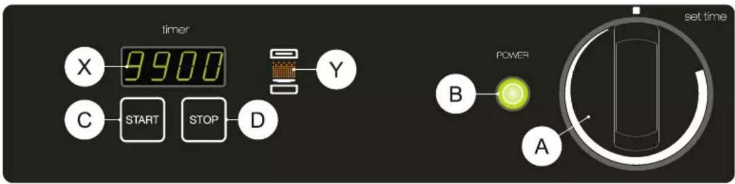
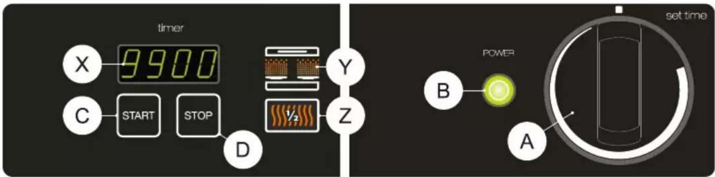
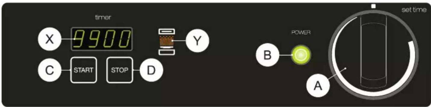
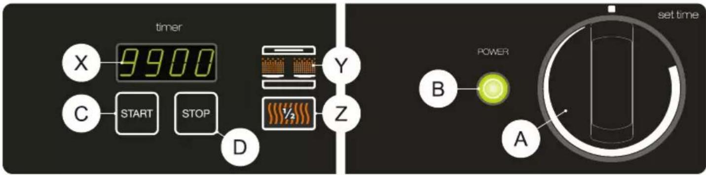
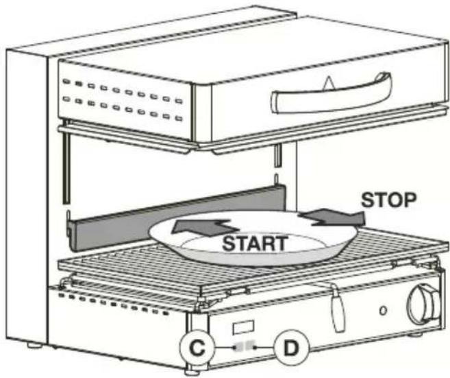
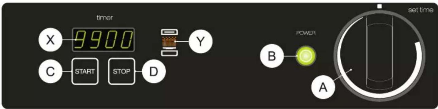
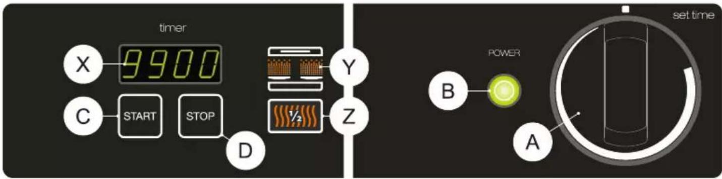
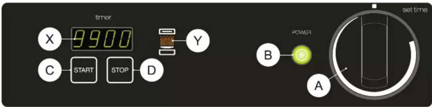
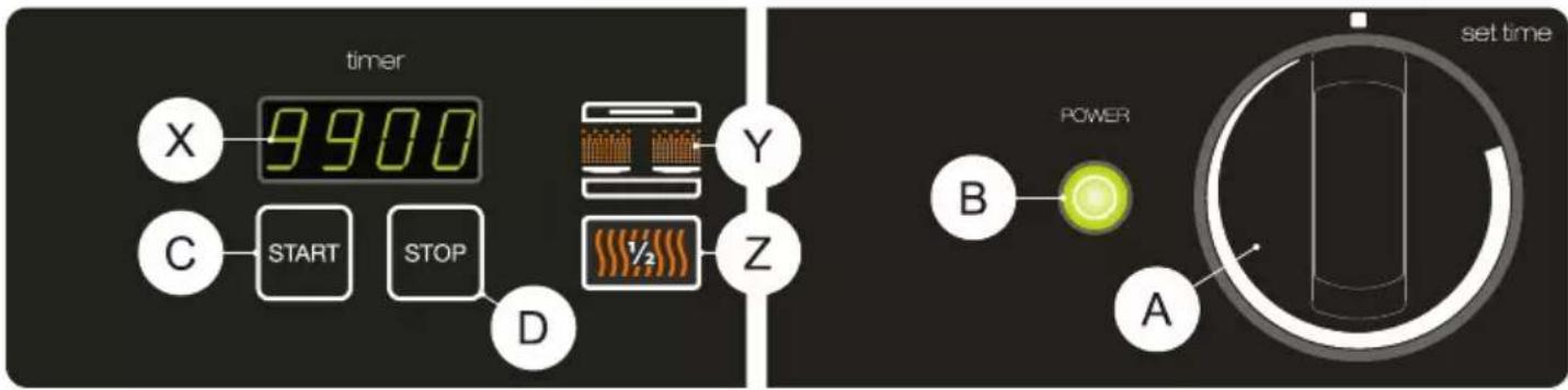
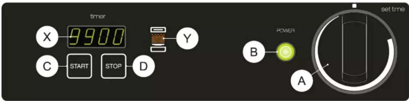
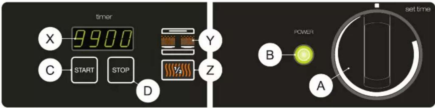
■ Turn the knob "A" clockwise setting the time that will be shown on the display "X" (minutes and seconds)
■ The green pilot light "B" turns on, and the orange pilot light "Y" flashes throughout the setup phase.
- Then press the "C" button to start cooking. The orange pilot light "Y" passes from flashing to fixed for all the time set. The appliance will remain on for the set time and the screen will show the time remaining before the appliance turns off; the point in the centre of the screen "X" flashes.
- The time set at the start of the cooking in progress is shown when holding down the "C" button while the appliance is working (point in the centre of the flashing screen).
- By holding down the "D" button, it will be possible to stop the appliance: the screen will show the cooking time set, and the
orange LED light "Y" starts flashing again. In these conditions cooking can be started again by pushing the "C" button again, or the time set can be changed using the knob "A".
■ An acoustic warning signals the end of the cooking cycle.
- To turn the appliance off bring the knob back to the "0" position.
ONLY QSE\_60
- Use the "Z" button to select half or all of the cooking surface for operation; the corresponding "Y" orange LED light turns on.
ONLY QSET\\_ MODELS
- The cooking cycle starts when pressing the bar with a plate (same function as button "C"). When the bar is released, the cycle stops (same function as button "D").
⚠ In the event of a power failure during cooking, the remaining cooking time will be shown by the flashing screen when power is restored.
The appliance will start again from this indication when pressing the "C" button or the bar for the QSET_ models.
TURNING THE APPLIANCE ON, USE AND TURNING THE APPLIANCE OFF SE\_40 - SE\_60 - SE80\_
■ Activate the switch located upstream of the appliance
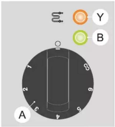
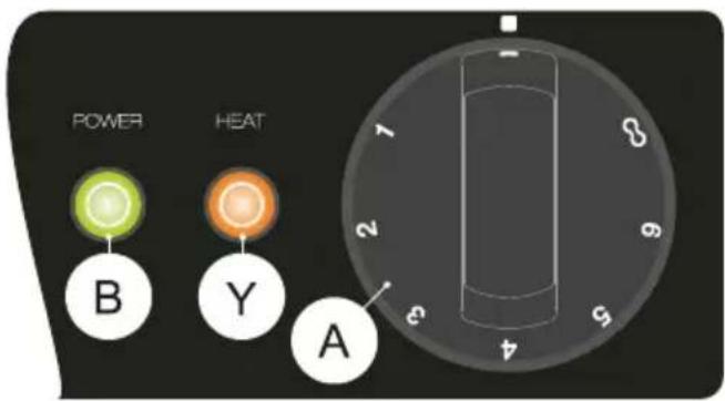
■ Turn knob "A" making the dashboard index coincide with the value on the knob 1 - 6 - ∞
- The green pilot light "B" turns on when there is power.
- The energy regulator supplies power to the resistors at regular intervals, and the orange pilot light "Y" turns on.
- The resistors always remain on when in the “∞” position.
- To turn the appliance off bring the knob back to the "0" position.
TURNING THE APPLIANCE ON, USE AND TURNING THE APPLIANCE OFF SEL\_
■ Activate the switch located upstream of the appliance
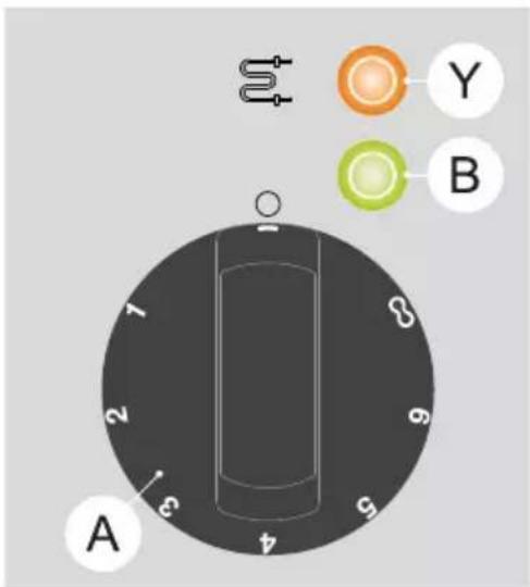
■ Turn knob "A" making the dashboard index coincide with the value on the knob 1 - 6 - ∞
■ The green pilot light "B" turns on when there is power.
- The energy regulator supplies power to the resistors at regular intervals, and the orange pilot light "Y" turns on.
- The resistors always remain on when in the “∞” position.
- To turn the appliance off bring the knob back to the "0" position.
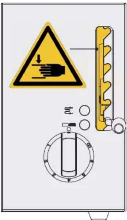
⚠ Do not put your fingers in the slot; there is a risk of crushing.
CLEANING AND CARE
⚠ Do not wash the appliance with jets of water or steam cleaning equipment.
■ Infiltration of water and steam in the electrical components could jeopardize the correct operation of the equipment and safety systems!
- If the appliance is not going to be used for a long period of time, disconnect it from the mains and subsequently clean it with soapy water, rinse it and dry it thoroughly. Spread a thin layer of liquid paraffin on the surface.
- The basin must be washed on a daily basis with soapy water.
- Let the appliance cool down before washing the basin or any other part.
- For QSE models only, clean the glass top regularly by applying a few drops of suitable detergent to the surface when cold and wipe with kitchen paper or a soft cloth. Then rinse and dry with kitchen paper or a clean cloth.
- Do not use sponges or abrasive products of any kind, and do not use corrosive detergents, such as oven sprays or stain removers.
- To minimise the emission of polluting substances into the environment, we suggest cleaning the appliance with products that are at least 90% biodegradable.
MAINTENANCE
The appliance does not require any specific maintenance besides normal cleaning; we do however suggest having it checked once a year
by the assistance centres. For this purpose a maintenance contract should be stipulated.
FAULTS
Malfunctions are not always explained by the quality of the components used. These appliances are manufactured using top quality components. Malfunctions may be caused by voltage surges, or by dust or dirt infiltrating the components. In any case, if anomalies are
suspected, ALWAYS turn the appliance off and call the authorised repair service.
These appliances are manufactured using high quality components. Malfunctions may be caused by voltage surges, dust and/or dirt infiltrating the components.
⚠️ Unauthorised persons should never attempt to repair the appliance, or carry out maintenance. Tampering with the appliance voids the warranty.
| MAINTENANCE - CHECKS - CONTROLS - CLEANING FREQUENCY USER | REPAIR SERVICE | |||
| Cleaning | General cleaning of the appliance and the surrounding areas | Daily or based on the degree of use | Yes - | |
| Safety devices | Check proper functioning of safety devices | Monthly Yes | Yes | |
| Mechanical protective devices | Check condition; check that there are no deformations, loose parts or missing parts. | Monthly Yes | Yes | |
| Controls | Check readability and condition of the inscriptions and symbols and repair if necessary. | Yearly | Yes | Yes |
| Structure of the appliance | Check the mechanical part to make sure that it is not broken or deformed, tighten the screws. | Yes | Yes | |
| Tighten the main bolts (screws, fasteners, etc.) of the appliance | - Yes | |||
| Safety signs | Check readability and condition of safety signs. | Yes | Yes | |
| Electrical control panel / electronics | Check the conditions of the electrical parts installed on the electrical control panel. | - Yes | ||
| Check the wiring between the electrical panel and parts of the appliance. | ||||
| Electrical connection cable and plug socket | Check the condition of the connection cable and plug socket. | Yes | Yes | |
| Replace if defective. | - Yes | |||
| Motor bearings (if present) | Replace motor bearings | Every three years | - Yes | |
ECOLOGY AND THE ENVIRONMENT
Our appliances are studied and optimised via testing to provide high performance and yields. However, in order to reduce energy consumption (electricity, gas and water), we suggest that you do not use the appliance for long periods of time without food or in conditions that may compromise optimum yield.
All of the following materials are used for the packaging:
■ Polyethylene: external packaging film and/or pluriball film
■ Polypropylene: straps.
■ Polystyrene foam: corner pieces, protective sheets and blocks.
- Cardboard
■ Wooden base frame
These materials are environmentally friendly and can be safely stored or reused/recycled and must be managed as waste in accordance with the provisions in force in your country.
⚠ Dispose of the appliance responsibly at the end of its useful life.
In compliance with the regulations in force in your country, dispose of the waste product by taking it to an authorised collection and treatment site (ecological centres or collection points), after removing the power cable.
TEIL 1 - GEBRAUCH
HINWEISE
natural_image
Technical line drawing of a multi-level industrial enclosure with internal components and ventilation ducts (no text or symbols)natural_image
Technical line drawing of a multi-level industrial enclosure with internal components and ventilation ducts (no text or symbols)ALLUMAGE, UTILISATION ET EXTINCTION QSE\_
Modèle QSE_40
flowchart
graph TD
    subgraph Timer
        X["Start"] --> 9900
        C["Start"] --> START
        STOP["Stop"] --> D["Second Order"]
        D --> 1/2
        Y["Order"] --> Z["Output"]
    end
    subgraph Power
        B["Power"] --> A["Set"]
    end
    style Timer fill:#f9f,stroke:#333
    style Power fill:#ccf,stroke:#333
Modèle QSE\_60
natural_image
Technical line drawing of a multi-level industrial enclosure with internal components and ventilation ducts (no text or symbols)ENCENDIDO, USO Y APAGADO DE APARATOS QSE\_
Modelo QSE_40
flowchart
graph TD
    subgraph Timer
        X["Start"] --> 9900
        C["Start"] --> START
        STOP["Stop"] --> D["Second Order"]
        D --> 1/2
        Y["Order"] --> Z["Output"]
    end
    subgraph Power
        B["Power"] --> A["Set"]
    end
    style Timer fill:#f9f,stroke:#333
    style Power fill:#ccf,stroke:#333
Modelo QSE\_60
natural_image
Technical line drawing of a multi-level industrial enclosure with internal components and ventilation ducts (no text or symbols)WŁĄCZANIE, UŻYTKOWANIE I WYŁĄCZANIE QSE\_
Model QSE_40
flowchart
graph TD
    subgraph Timer
        X["Start"] --> 9900
        C["Start"] --> START
        STOP["Stop"] --> D["Second Order"]
        D --> 1/2
        Y["Order"] --> Z["Output"]
    end
    subgraph Power
        B["Power"] --> A["Set"]
    end
    style Timer fill:#f9f,stroke:#333
    style Power fill:#ccf,stroke:#333
Model QSE\_60
natural_image
Technical line drawing of a multi-level industrial enclosure with internal components and ventilation ducts (no text or symbols)
- ACCENSIONE, USO E SPEGNIMENTO QSE\_
- Modello QSE\_60
- ACCENSIONE, USO E SPEGNIMENTO SEL\_
- INSTALLATION AND CONNECTION TO THE POWER SUPPLY
- TURNING THE APPLIANCE ON, USE AND TURNING THE APPLIANCE OFF QSE\_
- QSE\_60 model
- ONLY QSE\_60
- ONLY QSET\\_ MODELS
- TURNING THE APPLIANCE ON, USE AND TURNING THE APPLIANCE OFF SE\_40 - SE\_60 - SE80\_
- TURNING THE APPLIANCE ON, USE AND TURNING THE APPLIANCE OFF SEL\_
- CLEANING AND CARE
- MAINTENANCE
- FAULTS
- ECOLOGY AND THE ENVIRONMENT
- TEIL 1 - GEBRAUCH
- HINWEISE
- ALLUMAGE, UTILISATION ET EXTINCTION QSE\_
- Modèle QSE\_60
- ENCENDIDO, USO Y APAGADO DE APARATOS QSE\_
- Modelo QSE\_60
- WŁĄCZANIE, UŻYTKOWANIE I WYŁĄCZANIE QSE\_
- Model QSE\_60
Brand : MBM
Model : SAE641
Category : Oven