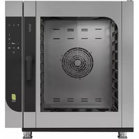
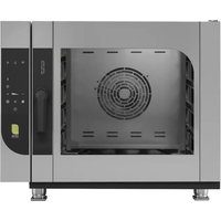
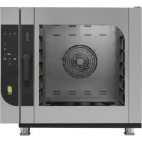
CME102 - Pizza oven MBM - Free user manual and instructions
Find the device manual for free CME102 MBM in PDF.


| Product type | Professional pizza oven |
| Brand | MBM |
| Model | CME102 |
| Category | Pizza oven |
| Usage | Professional, cooking and regeneration of food products |
| Power supply | Gas (gas burner) and electric (control) |
| Cooking modes | Convection (static and fan-assisted), Steam, Mixed, Proofing |
| Temperature range | 40 °C to 250 °C (convection and mixed), 40 °C to 100 °C (steam) |
| Timer | 1 minute to 9 hours, infinite mode possible |
| Programming | Up to 60 recipes, 5 phases per recipe, with core probe and delayed start |
| Core probe | Internal and external (dual probe possible), Delta T function |
| Special functions | Preheating, rapid cooling, programmed start, emergency stop |
| Display | Digital screen (4 displays) |
| User interface | Control panel with dedicated keys (temperature, time, fan, etc.) |
| Ventilation | Adjustable fan (1 to 6) or stop (proofing mode) |
| Humidity | Adjustable from 0% to 100% in mixed mode, relief valve |
| Cleaning | Automatic washing (quick, rinse, short, medium, long cycles) and manual washing |
| Maintenance | Daily cleaning, check filter, door gasket, condensation tray, drain tubes |
| Safety | Alarms (probe, overheating, water fault, flame failure), emergency stop, personal protective equipment required |
| Connectivity | USB port for import/export of recipes |
| Warranty | 12 months from invoice date, defective parts (excluding consumables) |
| Repairability | Interventions by authorized qualified personnel; original parts recommended |
Frequently Asked Questions - CME102 MBM
User questions about CME102 MBM
0 question about this device. Answer the ones you know or ask your own.
Ask a new question about this device
Download the instructions for your Pizza oven in PDF format for free! Find your manual CME102 - MBM and take your electronic device back in hand. On this page are published all the documents necessary for the use of your device. CME102 by MBM.
USER MANUAL CME102 MBM
natural_image
Two diagrams showing a medical procedure: one with a needle inserted into a patient's mouth, the other with a crossed-out surgical tool (no text or symbols present)A - SONDA AL CUORE (SINGLEPOINT, MULTIPOINT, SOTTOVUOTO)
natural_image
Technical line drawing of an open industrial oven with internal components and a cylindrical chamber (no text or symbols)
natural_image
Technical diagram of an oven with labeled components, showing internal structure and connection to a power outlet (no text or symbols beyond label)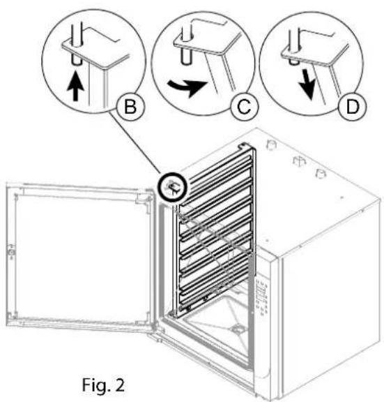
9.3 LAVAGGIO AUTOMATICO
Avvio LAVAGGIO
natural_image
Diagram of a fire extinguisher inside a cabinet, showing internal components and exhaust pipe (no text or labels)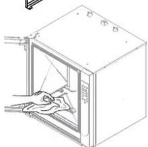
natural_image
Line drawing of a door with a hand cleaning the interior (no text or symbols)Fig.6
natural_image
Diagram of a refrigerant unit with labeled components (Fig. 12 and Fig. 13), showing internal components and wiring connections (no text or symbols beyond labels)natural_image
Simple gray icon of a human figure inside a rounded square frame (no text or symbols)FORNO ELETTRICO
ELECTRIC OVEN
FOUR ELECTRIQUE
ELEKTROBACKOFEN
ELEKTRISCHE OVEN
FORNO ELÉTRICO
PIEKARNIK ELEKTRYCZNY
ELEKTROMOS SÜTÖ

FORNO A GAS
OVEN GAS
FOUR A GAZ
GASBACKOFEN
GASOVEN
FORNO A GÁS
PIEKARNIK GAZOWY
GÁZSÜTŐ


0. DOCUMENT IDENTIFICATION
0.1 REFERENCE STANDARDS
1 INFORMATION FOR USERS
Foreword - Purpose of document - How to read the document - Keeping the document - Addressees - Operator training program - Preparations by the customer - Intended Use Conditions allowed for operation - Testing and warranty - Authorisation
2.2. GENERAL SAFETY INFORMATION
Description of pictograms - General personal protection procedures - Warning signs - Foreward - Obligations - Prohibitions - Advice - Recommendations Information on residual risks - Operating method for gas odours in room
3 OPERATING FUNCTIONS
Button functions and method - Operating mode for the control panel - Description of the operating modes - Language setting software - Shutdown modes description
4. COMMISSIONING
Commissioning for the first startup - Daily commissioning - Daily shutdown and long term shutdown - Production startup - Startup/Shutting down
5. OPERATING PARAMETERS
Date/Clock - Setting the temperature - Setting the time - Setting the humidity - Setting the venting valve (only convection) - Setting the fan speed - Setting the preheating - Setting the quick cooling - Setting the programmed start (delay)
6. COOKING PARAMETERS
Convection (Rising) - Steam - Combi - Core probe and Delta T
7 PROGRAMMING
Recipe Index (Save recipe - Edit recipe - Start recipe - Delete recipe) - USB DEVICE
8. LOADING AND UNLOADING THE PRODUCT
Loading and unloading the product
9. ROUTINE MAINTENANCE
Cleaning the appliance - Cleaning at first startup - Automatic washing - Manual washing - Periodic inspections
10 ALARM SIGNALS
List of alarms - Troubleshooting
DISPOSAL
Deactivating and scrapping the appliance - Waste disposal
Introduction
"Original instructions" This document has been drawn up in the mother language of the manufacturer (Italian). The information it contains is for the sole use of the operator authorised to use the appliance in question.
Operators must be trained concerning all aspects regarding functioning and safety. Special safety prescriptions are given in a specific chapter concerning these issues. GENERAL SAFETY INFORMATION This document cannot be handed over to third parties to take vision of it without written consent by the manufacturer. The text cannot be used in other publications without the written consent of the manufacturer.
The use of: Figures/Images/Drawings/Layouts inside the document, is purely indicative and can under-go variations. The manufacturer reserves the right to modify it, without being obliged to communicate his acts.
Scope of the document
Every type of interaction between the operator and the appliance during its entire life cycle has been carefully assessed both during designing and while drawing up this document. We therefore hope that this documentation can help to maintain the characteristic efficiency of the appliance. By strictly keeping to the indications it contains, the risk of injuries while working and/or of economical damage is limited to a minimum.
How to read the document
The document is divided into chapters which gather by topics all the information required to use the appliance in a risk-free way. Each chapter is divided into paragraphs; each paragraph can have titled clarifications with subtitles and descriptions.
Keeping the document
This document is an integral part of the initial supply. It must therefore be kept and used appropriately during the entire operational life of the appliance.
Addressees
This document is structured for the exclusive use of the “Generic” operator (Operator with limited responsibilities and tasks). Person authorised and employed to operate the appliance with guards active and capable of performing routine maintenance (cleaning the appliance).
Operator training program
Upon specific demand by the user, a training course can be held for operators in charge of using the appliance, following the modalities provided in the order confirmation.
Depending on the demand, preparation courses can be held at the site of manufacturer or of the user, for:
• Homogeneous operator in charge of electric/electronic maintenance (specialised technician);
• Homogeneous operator in charge of mechanical maintenance (specialised technician);
- Generic operator for simple operations (Operator - Final user).
Pre-arrangements depending on customer
Unless different contractual agreements were made, the following normally depend on the customer: • setting up the rooms (including masonry work, foundations or channelling that could be requested);
- smooth, slip-proof floor;
- pre-arrangement of installation place and installation of equipment respecting the dimensions indicated in the layout (foundation plan);
- pre-arrangement of auxiliary services adequate for requirements of the system (electrical mains, waterworks, gas network, drainage system);
- pre-arrangement of electrical system in compliance with regulatory provisions in force in the place of installation;
- sufficient lighting, in compliance with standards in force in the place of installation;
- safety devices upstream and downstream the energy supply line (residual current devices, equipotential earthing systems, safety valves, etc.) foreseen by legislation in force in the country of installation;
- earthing system in compliance with standards in force;
- pre-arrangement of a water softening system, if needed (see technical details).
Intended use
This device is designed for professional use. The use of the appliance treated in this document must be considered "Proper Use" if used for cooking or regeneration of goods intended for alimentary use; any other use is to be considered "Improper use" and therefore dangerous. The appliance must be used according to the foreseen conditions stated in the contract within the prescribed capacity limits carried in the respective paragraphs. Only use original accessories and spare parts supplied by the manufacturer to maintain regulatory compliance.
Allowed operating conditions
The appliance has been designed to operate only inside of rooms within the prescribed technical and capacity limits. The following indications must be observed in order to attain ideal operation and safe work conditions.
The appliance must be installed in a suitable place, namely, one which allows normal running, routine and extraordinary maintenance operations. The operating area for maintenance must be set up in such a way that the safety of the operator is not endangered.
The room must also be provided with the features required for installation, such as:
• minimum cooling water temperature > + 10 °C ;
• the floor must be anti-slip, and devices positioned perfectly level;
- the room must be equipped with a ventilation system and lighting as prescribed by standards in force in the country of the user;
- the room must be set up for draining greywater, and must have switches and gate valves which cut all types of supply upstream the appliance when needed;
• The walls around the appliance must be fireproof and/or insulated against possible heat sources.
Test inspection and warranty
Testing: the equipment has been tested by the manufacturer during the assembly stages at the site of the production plant.
All certificates related to the testing performed will be delivered to the customer upon request.
Warranty: The guarantee is of 12 months from invoice date and it covers the faulty parts only. Carriage and installation charges are for the buyer's account. Electric components, accessories as well as other removable parts are not covered by the guarantee.
Labor costs relating to the intervention of authorized by the manufacturer at the customer's premises, for removal of defects under warranty are charged to the dealer, except in cases where the nature of the defect is such that it can be easily removed on site by the customer.
Excluded are all tools and supplies, possibly supplied by the manufacturer together with the machines. Damage occurred in transit or due to incorrect installation or maintenance can't be considered. Guarantee is not transferable and replacement of parts and appliance is at the final discretion of our company. The manufacturer is responsible for the device in its original setting.
The manufacturer declines all responsibility for improper use, for damages caused as a result of operations not covered in this manual or not authorized in advance by the manufacturer.
The warranty terminates in case of:
- Damage caused by transportation and/or handling. Should this occur, the customer must inform the dealer and carrier via fax or RR and must write what has happened on the copies of the transportation documents. The specialised technician installing the appliance will assess whether it can be installed depending on the damage.
The warranty also terminates in the presence of:
- Damage caused by incorrect installation;
- Damage caused by parts worn due to improper use;
- Damage caused by use of unadvised or non-original spare parts;
- Damage caused by incorrect maintenance and/or lack of maintenance;
- Damage caused by failure to comply with the procedures described in this document.
Authorisation
Authorisation means the permission to undertake an activity related to the appliance.
Authorisation is given by the entity who is responsible for the appliance (manufacturer, purchaser, signatory, dealer and/or owner of the premises.
Description of pictograms
DANGER

General danger

Danger of electrocution

Danger from high temperatures

Danger of material at high temperatures

Danger of crushing limbs
PROHIBITIONS

Prohibition for the heterogeneous operator to perform any type of operation (mainte nance and/or other) that should instead be carried out by a qualified and authorised technician.

Prohibition for the homogeneous operator to perform any type of operation (mainte nance and/or other) without having first read the entire documentation.
OBLIGATION

Obligation to read the instructions before carrying out any work.

The electricity must be switched off whenever operating on the appliance under safety conditions.

Current legislation regarding the disposal of special waste must be respected.

Obligation to use safety goggles.

Obligation to use protective gloves.

Obligation to use a protective helmet.

Obligation to use safety shoes.

Obligation to use head wear to prevent accidental loss of hair.
Individual general protection measures to be adopted

Whenever the "cooking compartment" must be accessed, always remember that there is a burn hazard. It is therefore mandatory to take appropriate measures for personal protection.

Wear protective equipment suitable for the operations to be performed. Do not wear clothing and objects such as bracelets, necklaces or rings that could become entangled in the cooking compartment.

Read the instructions before performing any operations.

Turn off the electricity to the appliance whenever necessary to operate in safe conditions on the appliance.
Information plates on the appliance

There are plates and pictograms on the appliance that are described below. IT IS absolutely forbidden to tamper with or remove the plates or pictograms from the machine. It is the user's responsibility to verify periodically the integrity of the plates and pictograms attached to the machine. Remove and replace damaged ones by requesting them from the manufacturer.

General danger

Voltage present

High temperature material output

Earthing

Connecting to the equipotential system
Foreword
 | The operating instructions have been drawn up for the “Generic” operator (Operator with limited responsibilities and tasks). Person authorised and employed to operate the appliance with guards active and capable of performing routine maintenance (cleaning the appliance). |
 | The operators who use the appliance must be trained in all aspects concerning its functioning and safety features. They must therefore interact using appropriate methods and instruments, complying with required safety standards. |
 | This document does not include information regarding transportation, installation and extraordinary maintenance which must be performed by technicians qualified for the relevant operation. |
 | The "Generic" operator to whom this document is intended must operate on the appliance after the technician has completed installation (transportation, fixing electrical, water, gas and drain connections). |
 | This document does not include information regarding every modification or variation on the appliance. The manufacturer reserves the right to modify it, without being obliged to communicate his acts. |
Obligations - Restrictions - Suggestions - Recommendations
 | Upon reception, open the packaging and make sure that the appliance and accessories have been damaged during transportation. If there is any damage, inform the transporter immedia - tely of what was detected and do not install the appliance. Contact qualified and authorised personnel to report the problem detected. The manufacturer is not liable for damage caused during transportation. |
 | Unauthorised persons (including children, disabled individuals and people with limited physical, sensory and mental abilities) are prohibited from performing any procedures. Generic operators are prohibited from performing any procedures reserved for qualified and authorised technicians. |
 | Read the instructions before acting. |
 | Disconnect all supplies (electrical - gas - water) upstream the appliance whenever you need to work in safe conditions. |
 | Wear protective equipment suitable for the operations to be performed. As far as personal protective equipment is concerned, the European Community has issued Directives which the operators must comply with. Airborne noise ≤ 70 dB |
 | It is forbidden to obstruct the air vents on the appliance with grills, trays or other accessories that impede free air circulation. |
 | Do not leave flammable objects or material near the appliance. |
 | Refer to standards in force for disposal of special waste. |
 | When loading the product into the appliance and unloading it, there is a residual risk of being burnt; this risk can occur coming into unintentional contact with: surfaces, pans, material treated. |
 | Use the cooking vessels in such a way that while the product is cooking, they are in the opera - tor's sight. Liquid containers can spill during cooking, thus creating dangerous situations. |
 | Failure to keep the appliance in hygienic conditions could cause it to deteriorate quickly, influencing operation and creating dangerous situations. |
 | It is strictly forbidden to tamper with or remove the plates and pictograms applied to the equipment. |
 | Store this document carefully, so that it is available for whoever uses the appliance, consulting it when needed. |
 | The controls on the appliance can only be switched by hand. Damage caused by sharp objects or the likes terminate all and any warranty rights. |
 | In order to minimise the risk of shocks or fire, do not connect or disconnect the unit with wet hands. |
 | Whenever you access the cooking area, always remember that the danger of being burnt persists. Therefore, suitable personal protection measures. |
THE PRESENT MANUAL IS PROPERTY OF THE MANUFACTURER. ANY REPRODUCTION, EVEN PARTIAL, IS PROHIBITED.
Indications concerning residual risks
Even though the rules for “good manufacturing practice” and the provisions of law which regulate manufacturing and marketing of the product have been implemented, “residual risks” still remain which, due to the very nature of the appliance, it has not been possible to eliminate. These risks include:
 | Residual risk of electrocution:Such risk persists if you have to operate electrical and/or electronic devices under voltage. |
 | Residual risk of burning:Such risk persists if the operator comes accidentally into contact with materials at high temperature. |
 | Residual risk of burning due to material leakSuch risk persists if the operator comes accidentally into contact with leaking material at high temperature. Overfilled containers with liquids and/or solids that change morphology during heating (switching from solid to liquid state), may cause burns, if used improperly. During work, the containers should be placed at levels that ensure good visibility. |
 | Residual risk of explosion• if there is gas odour in the room;• use of the equipment in atmosphere containing substances at risk of explosion;• use of foodstuff in close containers (such as barrels and boxes), that are not suitable for such purpose. |
 | Residual risk of fireThis risk remains when:• using with flammable liquids (such as alcohol). |
What to do when there is a gas odour in the area

If there is a smell of gas in the environment, it is mandatory to urgently implement the procedures described below.
- Immediately stop the gas supply (Close the network tap, detail A).
• Ventilate the room immediately. - Do not operate any electrical device in the environment (Detail B-C-D).
- Do not operate any device which could produce sparks or flames (Detail B-C-D).
- Use a means of communication that is external to the environment where there is a smell of gas to warn the relevant entities (electricity operator and/or firefighters).


BCD

3.1 Mode and function of buttons
The layout of the figures is purely indicative and can undergo variations.

"CONVECTION" button: "Convection" cooking mode.

"STEAM" button: "Steam" cooking mode.

"Combi" button: "combi" cooking mode.

"TEMPERATURE" button: cooking temperature.

"TIME" button: cooking time.

"LESS" More" and "SCROLL" button: to decrease or increase the selected parameter.

MENU button: to enter, return to the main menu and exit a function.

FAN button: fan speed in the cooking chamber.

"VENT" button: valve open (flashing led), valve closed (fixed led).

"ENTER" button: turn on and turn off the oven. Validate/stop fun -ction.
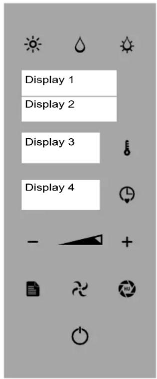
Fig.1
3.2 Control panel operation
The keys are used in relation to the desired process. They can be used to call up or program various functions.
The "ENTER" key can be selected to perform 4 different functions:
- Manual cooking (default CONVECTION-STEAM-COMBI)
- Stop or start a work cycle (and/or consent to access a specific function, e.g., core probe cooking, delayed start).
- Confirm a setting choice.
- Pause the current function (press the "ENTER" button to resume the cycle-PAUSE function).
The "TIME" and "TEMPERATURE" keys pressed at the same time set the clock.
3.3 Description of the operating modes
- OFF mode: "enter" button (after 15 minutes in STAND BY").
- "STAND BY mode: ENTER button lit and clock display (FIG. 1 DISPLAY 3).
- "MAIN MENU" MODE, ENTER KEY LIT, CLOCK DISPLAY (FIG.1 DISPLAY 3) AND DISPLAY OF FUNCTIONS (WASH - RECIPES-CORE PROBE-POST- SAVE RECIPES - IMPORT RECIPES - UPDATE FW - OFF - FIG.1 - DISPLAY 1).

The instructions in this manual are for the oven in “STAND BY” and with the parameters set by the manufacturer, where not otherwise indicated.
In “function selection” or “parameter selection” mode, after 5 seconds of inactivity the oven memorizes the function or value displayed (Fig.1 Display 2 - 3 - 4).
The cooking types can be managed by the user in two modes:
- Manual mode: the operator sets the operating parameters each time.
- Automatic mode: the operator sets the operation by selecting a cooking program (see 7.1 Recipe Index).
The “Program” and/ cooking “Recipe” can be called up or repeated as needed. The appliance can save up to 60 programs. The duration of each program cannot exceed 9 hours of consecutive operation. Inside the “Program”, 5 cooking phases are possible. The “Cooking Phase” highlighted by the word “PHASE” (Fig.1 Display 2) indicates the cooking characteristics used to treat the food.
When using a "Recipe" with several processing phases, the appliance ends the cooking cycle at the end of the last memorized phase (see 7.1. 7.1 Recipe Index).
When using the appliance in MANUAL mode, the operator must set all of the desired cooking parameters each time (see 6. Cooking).
When you use the equipment in CORE PROBE mode during manual coo-king and/or recipe phase, the MAIN core probe is always enabled (internal, if both present, or the one installed).
3.4 Software language setup
The oven is set to Italian. Upon first start-up, the following will be displayed:
Example: Display 1 shows "LINGUA"
Display 2 shows "P 01"
Display 3 shows "ITA"
To select the desired language press the "TIME" key (Fig 2/E - Display 4) and use keys "PLUS" and "MINUS" (Fig 2/B) to select the language. Press the key "TIME" (Fig 2/E) to confirm.
Press the key "ENTER" (Fig.2/A) twice for 3 seconds to save and exit the function.

With the electrical power supply stopped upstream of the appliance for longer than 100 hours, reset the software language.

Fig.2
3.5 Description of stop modes
The description of the various stop modes are described as follows:

In the event of imminent danger, close all of the locking devices connected to the appliance (Electrical - Water - Gas).
1. Emergency stop
In situations or circumstances that could be dangerous, shut off the electricity upstream of the oven.
Restarting:
To restart the production cycle, contact the authorised service centre.
2. Stoppage during a work phase
To stop the operation of the production cycle, proceed as follows:
Press "ENTER" (Fig. 2/A) to stop the operations,
In "POST." or "WASHING" mode, press "ENTER" (Fig. 2/A) for 3 seconds.
Restarting:
To restart the production cycle after a shutdown, follow the procedure given in: Daily activation
3. Stop due to opening the door during operation
The appliance can be immediately stopped by opening the door.
Restarting:
After having resolved the issue that made it necessary to open the door, an authorised operator can restart the appliance by closing the door.

The appliance has hot surfaces: glass, door and front side. When the oven is hot, open the door carefully, standing to the side of the appliance to avoid direct heat: the setam accumulated may cause burns.
4.1 Commissioning

When commissioning the appliance and when starting it after a prolonged stop, it must be thoroughly cleaned to eliminate all residue of extraneous material (see Routine maintenance).


Cleaning at commissioning
Do not use pressurised or direct water jets to clean the appliance. Remove the outer protective film by hand and thoroughly clean all the outside parts of the appliance. When finished with the cleaning described for the outside of the appliance, proceed as described in "Daily Cleaning" (see 9 Routine maintenance).
4.2 Daily activation
Procedure:
- Check the cleanliness and hygiene of the appliance.
- Make sure that the room exhaust system works properly.
- When necessary, plug the appliance into the appropriate socket.
- Open the network locks upstream the appliance (Gas - Water - Electric).
- Make sure that the water drain (if present) is not clogged.
- Proceed with the operations described in "Starting production".
4.3 Daily and prolonged deactivation
Procedure:
- Close the network locks upstream the appliance (Gas - Water - Electric).
- Make sure that the drain cocks (if present) are "Closed".
- Check the cleanliness and hygiene of the appliance(See Routine Maintenance).

In the event of prolonged inactivity, protect the parts more exposed to oxidation as described in the specific chapter (See Routine Maintenance). Routine maintenance).
4.4 Starting production

Before proceeding with these operations, see "Daily activation".

When loading the product into the appliance and unloading it, there is a residual risk of being burnt; this risk can occur coming into unintentional contact with: cooking compartment, pans, material treated.

Take appropriate measures for personal protection. Wear protective equipment suitable for the operations to be performed.

4.5 Turning-on/Turning-off
Press the "ENTER" button (Fig 1/A) and proceed to manual cooking (see 6.1) o press the "MENU" key (Fig 1/B) to activate the main menu (Fig 6.1/B). Use the "MINUS" and "PLUS" keys to select the desired function (Fig 1/C). Press "ENTER" to confirm.

In function selection mode, after 5 seconds of inactivity the oven memorizes the function or value displayed (Display 2 - 3 - 4).
To proceed with shutdown:
- In main menu mode, press the "MINUS" or "PLUS" (Fig. 1/C) to the "OFF" function (Display 1). Press "ENTER" (FIG 1/A) TO CONFIRM.
- In function mode, press the "ENTER" button to stop the operation, press
"MENù" button (Fig. 1/B) and press the "MINUS" button (Fig. 1/C) to display the "OFF" function (Display 1). Press "ENTER" button (Fig. 1/A-see 3.3 Description of operating modes).
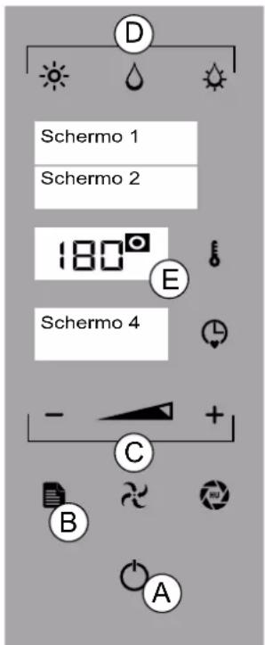
Fig.1

Before proceeding read carefully section 3 "Operating Features"
5.1 DATE/CLOCK
To set the date and time, press for 3 seconds the "TIME" and "TEMPERATURE" keys (Fig 1/D+E)
Example: Display 1 shows "YEAR". Display 2 shows "2019"
Use the "MINUS" and "PLUS" keys (Fig 1/B) select the current year and press the "ENTER"KEY (FIG 1/A) TO CONFIRM.

To save the "MONTH", "DAY", "HOUR" and "MINUTES", repeat the last operation
5.2 SETTING THE TEMPERATURE
Press Enter key (Fig 1/A) Select a cooking mode (Fig 1/C). Press "TEMPERATURE" (Fig 1/D - Display 3) and use the "MINUS", "PLUS" or "SCROLL" (Fig 1/B) to set the temperature from 40° and 250°.

In STEAM mode, the temperature is between 40^ and 100^

To display the set temperature, press the "TEMPERATURE" key (Fig. 1/D - Display 3).
Press "TEMPERATURE" to confirm (Fig 1/D).
To exit and return to the main menu press "MENU" button (Figure 1/H).
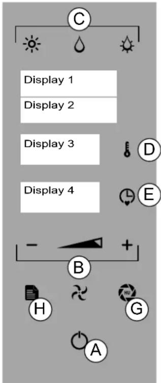
Fig.1
5.3 SETTING THE TIME
Press ENTER key (Fig 1/A) Select a cooking mode (Fig 1/C).
Press the "TIME" key (Fig 1/E - Display 4) and use the "MINUS", "PLUS" or "SCROLL" keys (Fig 1/B) set the time from infinity, 1 minute and 09:00 hours/minutes. The set cooking time is shown on Display 4. Press "TEMPERATURE" to confirm (Fig 1/E).

The time must be set in order to start the oven.
In "infinity" mode, the time to increase is displayed and in "set time" mode, the countdown time is shown (Fig. 1/E - Display 4).

To display the set time, press the "TIME" key (Fig. 1/E)
To exit and return to the main menu press "MENU" button (Figure 1/H).
5.4 MOISTURE SETUP
Press Enter key (Fig 1/A) Select the "COMBI" cooking mode (Fig 1/C). PRESS THE "VENT" key (Fig 1/G) and use the "MINUS" and "PLUS" keys (Fig 1/B) to set the percentage of humidity between 0% AND 100% (Fig 1/E - Display 1). Press the VENT key to confirm (Fig 1/G).
5.5 SETTING THE VENT (CONVECTIONonly)
Press ENTER key (Fig 1/A) PRESS THE"VENT" key (Fig 1/G - flashing LED/VENT OPEN, steady LED/VENT CLOSED) to open or close the oven vent valve.

Selecting "VENT OPEN" mode allows the humidity to escape from the cooking compartment while "VENT CLOSED" KEEPS THE HUMIDITY INSIDE.

By setting the "COMBI" functions or "Steam", the "open/closed" valve setting is controlled automatically.
5.6 SETTING THE FAN SPEED
Press ENTER key (Fig 1/A) Select a cooking mode (Fig 2/C):
Press the "FAN" key (Fig 2/F) and use the "MINUS" and "PLUS" keys to select a value between 2 and 1.
Press "FAN" to confirm.

The "RISING" function can be activated (see Cooking parameters "CONVECTION"). In the specific case, the fan can be set to "ZERO".
5.7 SETTING THE PREHEATING
Press ENTER key (Fig 1/A) Select a cooking mode (Fig 2/C). Set the temperature (see 5.2 SETTING THE TEMPERATURE).
Set the time (see 5.3 SETTING THE TIME).
Press the selected cooking mode for 3 seconds(Fig 2/C) and press "EN - TER" (Fig 2/A) to start the function.

"PREHEATING" phase (Fig. 2- Display 2): 20^ greater than the temperature set for the "CONVECTION" and "MIXED" function, 10^ greater than the temperature set for the "STEAM" function.
When preheating is done, "LOAD" appears on the display (Fig. 2- Display 2): Open the door and insert the product. When finished loading, close the oven door.
The set function starts.
Press the "ENTER" button (Fig. 2/A) for 3 seconds to stop the preheating and the "MENU" button (Fig. 2/H) to return to the main menu.
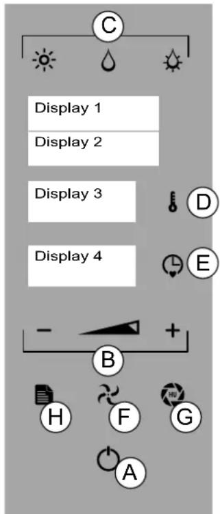
Fig.2
5.8 SETTING FAST COOLING
To quickly lower the temperature in the oven chamber, press "ENTER" (fig. 2A) and press the current cooking mode (Fig. 2/C). Press "TEMPERATURE" and use the "MINUS", "PLUS" or "SCROLL" (Fig 2/B) to set the temperature up to a minimum of 40^ .
Press "ENTER" to confirm.
For example: Display 1 shows "COOLING".
When cooling is complete "END" appears on Display 2. Press "MENU" (Fig 2/H) to access the main menu.
5.9 SETTING THE PROGRAMMED START (POSTPONEMENT)

To proceed with this function, the clock must be set (see 5.1. 5.1 DATE/CLOCK)
Press "ENTER" (Fig 2/A) and "MENU" (Fig 2/H) to activate the main menu. Use the "MINUS" and "PLUS" keys (Fig 2/B) to select the POST function.
Press "ENTER" and use the "MINUS" and "PLUS" to select "RECIPE" or "WASH". Press "ENTER" to confirm (Fig 2/A).
Press "TIME" (Fig 2/E), use the "MINUS", "PLUS" or "SCROLL" keys (Fig 2/B) to select the program start time. Press "TIME" to confirm (Fig 2/E). Press "ENTER" (Fig 2/A) and select the recipe or the washing cycle using the "MINUS" and "PLUS" keys (Fig 2/B).
Press "ENTER" (Fig 2/A) to confirm.

The delay time flashes(Fig. 2- Display 4)

For the "RECIPE" function there is no preheating.
When the set time is reached, the selected function is started and the time countdown starts.
Press the “MENU” button (Fig. 2/H) to cancel the programmed function and return to the main menu (Fig. 2/A).
THE PRESENT MANUAL IS PROPERTY OF THE MANUFACTURER. ANY REPRODUCTION, EVEN PARTIAL, IS PROHIBITED.

Before proceeding read carefully section 3 "Operating Features"
6.1 CONVECTION (RISING)- STEAM - COMBI
CONVECTION: Cooking without ventilation (static) and with ventilation. Default function.
STEAM: delicate cooking, defrosting and heating products.
COMBI: mixed cooking, with convection and humidity.
Press the "ENTER" button (Fig. 1/A) and select the desired cooking mode (Fig. 1/C-1 Display 1).
Set the temperature (see 5.2 SETTING THE TEMPERATURE).
Set the time (see 5.3 SETTING THE TIME).

When cooking without setting a time the oven can be stopped manually by the operation.

In the "CONVECTION" mode only, you can set the "VENT" (see SETTING THE VENT Setting the fan speed (see 5.5 Setting the fan speed)
Set the fan speed (see 5.6 Setting the fan speed).

Press for 3 seconds the "TIME" button (Figure 1/E) to set up the core probe (see 3.1 and 6.2/A -point 4).
Press "ENTER" (Fig 1/A) to start cooking.
On Display 4 the time starts to count down (set time mode) or increase (in - finity time mode).
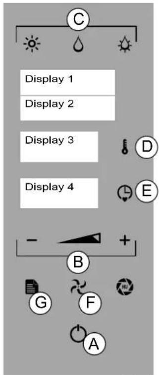
Fig.1

During the "COOKING" function it is possible to switch from one mode to another (CON-VECTION, STEAM, COMBI) and change all parameters (time, temperature, fan, vent - 5)

To start the "PREHEATING" function see 5.7
To exit and return to the main menu press "MENU" button (Figure 1/G).
PROVING
For bread and pastry making.

The "PROVING" mode function can only be set in "CONVECTION" mode.
Press the ENTER and the FAN key (Fig 1/F) and use the "MINUS" key to choose "ZERO"(Fig 1 - Display 2).
Press "FAN" to confirm.
Press "TEMPERATURE" (Fig 1/D) and use the "MINUS", "PLUS" or "SCROLL" to set the temperature from 25^ to 40^ .
Press "TEMPERATURE" to confirm.
Press the "TIME" key (Fig 1/E - Display 4) and use the "MINUS", "PLUS" or "SCROLL" keys (Fig 1/B) set the time from infinity, 1 minute and 09:00 hours/minutes.
Press "ENTER" to confirm the function.
6.2 CORE PROBE AND DELTA T
The probe detects the internal temperature of a product during cooking. The cooking time cannot be set or calculated while using the probe. The cooking cycle ends when the temperature of the product reaches the one set for the probe.
There are three ways to manage the oven temperature while using the core probe mode.
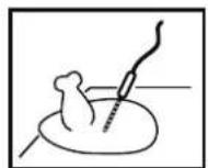
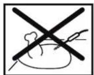
A - CORE PROBE (SINGLEPOINT, MULTIPOINT, VACUUM)
- Insert the pointed end of the probe in the product (on the tray inside the cooking chamber) until it is located in the centre of the product.
- Close the oven door, press "ENTER" (Fig 1/A) and MENU (Fig 1/F). Use the "MINUS" and "PLUS" keys (Fig 1/B) to select the CORE PROBE function. Press ENTER to confirm.
- Use the "MINUS" and "PLUS" keys (Fig 1/B) to select the CORE PRO-BE function.
- Select the cooking mode (Fig. 1/C), temperature (Fig. 1/D), probe temperature (Figure 1/E) and the desired parameters (see chap. 5).
Press "ENTER" (Fig 1/A) to start the cooking cycle.

The cord temperature can be set up to 99°C
Example: Display 1 shows "CONV. - CORE PROBE Display 4 shows "I 90"
To exit and return to the main menu press "MENU" button (Figure 1/F).
B - DELTA T

You can set only delta T with the inner core probe
Repeat the procedure described above in points 1 and 2.
- Use the "MINUS" and "PLUS" keys (Fig 1/B) to select the DELTA T function.
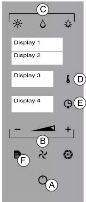
Fig.1
Press "TEMPERATURE" (Fig 1/D) and set the constant temperature difference between the cooking chamber and core probe between 20^ and 120^ .
Press "TEMPERATURE" to confirm. Select the desired parameters (see section 5).
Press "TIME" (Fig 1/E) and use "MINUS", "PLUS" or "SCROLL" (Fig 1/B) to set the temperature of the core probe.
Press "ENTER" (Fig 1/A) to start the cooking cycle.
Example: Display 1 shows "CONV. - DELTA T"
Display 3 shows "60" Display 4 shows "1 50"
To exit and return to the main menu press "MENU" button (Figure 1/F).

The core probe function and delta T can be set in all cooking mode and/or recipe phases
C - DUAL CORE PROBE (SINGLEPOINT, MULTIPOINT, UNDER VA-CUUM)
You can cook two types of products in a single cooking cycle. Proceed as follows:
- Insert the external core probe into the special compartment below oven panel.
- Insert the sharp end of the external core probe inside the product (placed on a tray inside the cooking chamber) so that the tip is approximately in the middle of the product.
3 Insert the sharp end of the internal core probe inside the product (pla -ced on a tray inside the cooking chamber) so that the tip is approximately in the middle of the product. - Close the door of the oven making sure the external core probe remains connected.
Close the oven door, press "ENTER" (Fig 1/A) MENU (Fig 1/F) to enter the main menu.
Use the "MINUS" and "PLUS" keys (Fig 1/B) to select the DUAL CORE PROBE function. Press "ENTER" (Fig 1/A) to confirm.
- Select the cooking mode (Fig 1/C), temperature (Fig. 1/E), probe temperature (Figure 5/E) and the desired parameters (see chap. 5).
Example: Display 3 shows "INT" Display 4 shows "70"
- Press the TIME key (Fig 1/E) and select the cooking mode (Fig 1/C), the probe temperature (Fig 1/E) and the desired parameters (see chap. 5 for the external core probe.
Example: Display 3 shows "EXT" Display 4 shows "65"

You can set the temperature of core probes up to 99°C
7 Press "TIME" button (Figure 1/E) and the "TEMPERATURE" button (Fig. 1/D) to set the temperature of the cooking chamber. Press "TEMPERATU-RE" to confirm.
Press "ENTER" (Fig 1/A) to start the cooking cycle.
8 To exit the function press "MENU (FIG. 1/F).
9 To change the temperature of the probes, press "TIME" and repeat the operations at points 5 and 6.
To change the temperature of the firing chamber press "TEMPERATURE" button and repeat step 7.
When the lower temperature set is reached, the writing "END" (Fig. 1- Di - splay 4):
When the upper temperature set is reached, the writing "END" (Fig. 1 Di - splay 4) and "MAINTENANCE". appears on the display.
The oven maintains the lowest temperature set (Fig. 1- Display 2):
To exit and return to the main menu press "MENU" button (Figure 1/F).

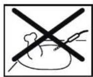
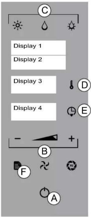
Fig.1

Before proceeding read carefully section 3 "Operating Features"
7.1 Recipe Index
Save Recipe
Press "ENTER" to activate the main menu (Fig. 1/A). Press the MENU key. Use the "MINUS" and "PLUS" (Fig 1/B) to select the RECIPE function and press ENTER to confirm.
For example: Display 1 shows "MENU1" Display 2 shows "NEW"
Press ENTER and the desired cooking mode: CONVECTION, STEAM, COMBI, RISING (Fig 1/C).
Set the temperature (see 5.2 SETTING THE TEMPERATURE). Set the time (see 5.3 SETTING THE TIME).

The time must be set (not infinity) in order to switch to the next phase
Press "plus" (Fig 1/I) and repeat the operation to save the other phases.

Press for 3 seconds the "TIME" button (Figure 1/E) to set up the core probe (see 3.1 and 6.2/A -point 4).

"Stage door": press the "LESS" and "more" (Fig 1/L + s). This stage recalls the operator to open the door to make changes to the product being cooked (e.g. by adding ingredients)

60 recipes and 5 phases/recipe can be saved
Press "ENTER" for 3 seconds to save the name of the recipe (Fig 1/A).
Example: Display 1 shows“-” Display 2 shows“-”
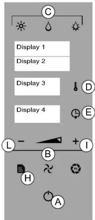
Fig.1
Press "MINUS" and "MINUS", "PLUS" or "SCROLL" (Fig 1/B) to select the first letter of the recipe. Press the "enter" button to validate the letter, in case of compilation error press MENU button (Figure 1/H). Proceed with completing the name of the recipe.
Press "ENTER" for 3 seconds to save the name of the recipe (Fig 1/A).
For example: Display 1 shows "MENU1" Display 2 shows "CHICKEN"
Press "MENU" to return to the main menu.
Modify RECIPE
The functions (convection, STEAM, COMBI, RISING), parameters (time, temperature, fan, vent) and the phases of a recipe can be edited (see Save Recipe).
At the end of the operation, press "ENTER" (Fig 1/A).
Press "ENTER" for 3 seconds to validate the changes and press the "enter" button for 3 seconds to save the recipe changed. To exit, press "MENU" (Fig 1/H).
DELETE PHASE
Press "ENTER" to activate the main menu (Fig. 1/A). Press the MENU" key. Use the "MINUS" a "PLUS" (Fig 1/B) to select the RECIPE function and press ENTER to confirm. Use the "MINUS" and PLUS" keys to choose the recipe that you want to edit and press the "ENTER" button to select it. Use the "MINUS" and "PLUS" keys (Fig 1/B) to select the phase to delete.
Press "TIME" and "MINUS" (Fig. 1/L) to reset the time.
For example: Display 4 shows“-”
Press "ENTER" for 3 seconds to validate the change and press the ENTER for 3 seconds to save the deletion. To exit, press "MENU" (Fig 1/H).
Start RECIPE
Use the ENTER key (Fig. 2/A) and press "MENU" (Fig 2/C), then select the RECIPE". function using the keys MINUS and PLUS (Fig. 2/B). Press EN - TER (Fig 2/A) and MINUS and PLUS or "SCROLL" keys (Fig 2/B) to select the recipe desired.
Press ENTER to start preheating (see 5.7 preheating setting).

To interrupt the recipe and return to the main menu press "MENU" button (Figure 2/C).
Delete RECIPE
Use the ENTER key (Fig. 2/A) and press "MENU" then select the RECIPE". function using the keys MINUS and PLUS or SCROLL (Fig. 2/B). Press Enter.
Select the recipe you want to delete using the "MINUS and PLUS or SCROLL keys. Press "PLUS" for 3 seconds.
Press ENTER to confirm (Fig 2/A).
To exit and return to the main menu press "MENU" button.
7.2 USB DEVICE
Uploading RECIPES
To save the recipes saved to the USB device in the oven, follow the steps below:
in STANDBY mode, press "ENTER" (Fig 2/A) and MENU (Fig 2/C). Use the "MINUS" and "PLUS" keys (Fig. 2/B) to display "Import recipes" (Display
2). Open the door below oven's panel and insert the USB device. Press "ENTER" to confirm (Fig 2/A)..
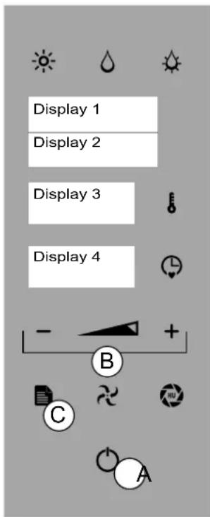
Fig.2
Example: Display 1 shows "USB"
Display 2 shows "READ"
Display 3 shows "RUNNING"
Display 4 shows the progress of the recipes loaded
(P 1, P 2, P 3 etc)
Example: Display 1 shows "USB"
Display 2 shows "FINISH"
Remove the USB device. Close the door.
Press "MENU" (Fig 2/C) to return to the main menu.
Downloading RECIPES
To save the recipes of the oven in the USB device, follow the steps below:
in STANDBY mode, press "ENTER" (Fig 2/A) and MENU (Fig 2/C). Use the "MINUS" and "PLUS" keys (Fig. 2/B) to display "Save Recipes" (Display 2). Open the door below oven's panel and insert the USB device.
Press "ENTER" to confirm (Fig 2/A)..
Example: Display 1 shows "USB"
Display 2 shows "SAVE"
Display 3 shows "RUNNING"
Display 4 shows the progress of the recipes downloaded
(P 1, P 2, P 3 etc)
Wait until the recipes are downloaded completely.
Example: Display 1 shows "USB"
Display 2 shows "FINISH"
Remove the USB device. Close the door.
Press "MENU" (Fig 2/C) to return to the main menu.
8.
LOADING AND UNLOADING THE PRODUCT

When loading the product into the appliance and unloading it, there is a residual risk of being burnt; this risk can occur coming into unintentional contact with the cooking compartment, trays or recipients or processed material

Whenever the "cooking compartment" must be accessed, always remember that there is a burn hazard. It is therefore mandatory to take appropriate measures for personal protection. Wear protective equipment that is suited to the operations to be performed.

Wear the proper individual protective clothing before proceeding with cleaning operations (gloves, mask, goggles)

Open the door while standing to the side of the appliance to avoid direct heat

Door opening: hold the handle, turn right or left and pull to release the spring mechanism. Door closing: hold the handle and push the door to lock the spring mechanism.

See section 5. Work parameters" before loading the oven
LOADING THE PRODUCT
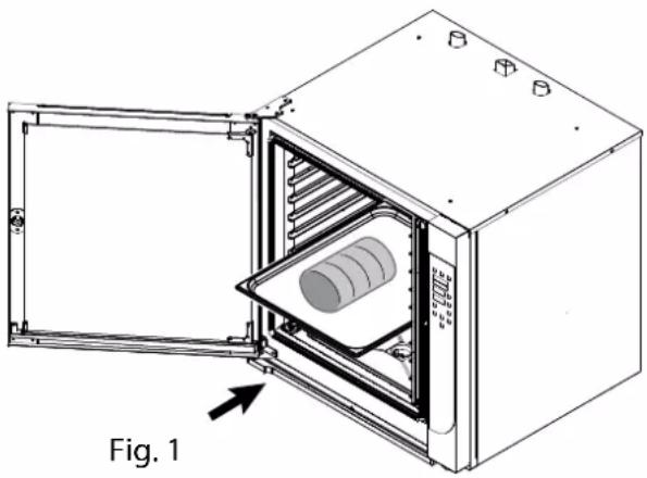
Load the product to be processed on tray(s) and insert on the tray holders previously installed in the oven. (Fig. 1.
Start the commissioning procedure daily (see 4. Commissioning or Programming (see 7 PROGRAMMING)
UNLOADING THE PRODUCT
Open the oven door and unload the trays from the tray holder using the appropriate personal protection equipment.

Once you have finished processing, if necessary, start the maintenance procedure (see 9 Routine maintenance).
natural_image
Technical line drawing of an open industrial oven with internal cooling unit and cylindrical component (no text or symbols)9.1 CLEANING THE APPLIANCE - General remarks

The appliance is used to prepare food products. Keep the appliance and the surrounding area constantly clean.

The appliance must be cleaned regularly and every incrustation or food deposit removed.

The appliance must be cleaned with the cooking compartment empty

In the event of prolonged inactivity, besides disconnecting the supply lines, you must thoroughly clean all the inside and outside parts of the appliance.

Whenever the "cooking compartment" must be accessed, always remember that there is a burn hazard. It is therefore mandatory to take appropriate measures for personal protection. Wear protective equipment that is suited to the operations to be performed.

Wear the proper individual protective clothing before proceeding with cleaning operations (gloves, mask, goggles)

Open the door while standing to the side of the appliance to avoid direct heat

The chemical effect of salt and/or vinegar or other acid substances can in the long run cause the inside of the cooking chamber to corrode during cooking. At the end of the cooking cycle for these substances, the appliance must be washed thoroughly with de-tergent and thoroughly rinsed.

The liquid detergent for cleaning the cooking compartment must have certain chemical features: - pH greater than 12 - without chlorides/ammonia and with a viscosity and density similar to water.

Thoroughly read the information on the detergent product labels. Wear protective equipment suitable for the operations to be performed. (See the protection methods on the package label)

Use non-aggressive products for cleaning the outside of the appliance (use detergents on the market for cleaning steel and glass).

Be careful not to damage stainless steel surfaces. Do not use corrosive products, abrasive material or sharp tools.

Rinse the surfaces with tap water and dry them with an absorbent cloth or other non-abrasive material.

Do not clean the appliance with direct jets of water and/or water under pressure.

When cleaning is finished, for good door seal maintenance, clean the gaskets with water and neutral soap, dry thoroughly and, once dry, put talcum powder on the surface of the gaskets. For proper gasket maintenance, this operation must be performed weekly

Cleaning of aeration apertures: Cooling the electronic compartment is ensured by means of the ventilation apertures at the right front of the equipment (6 and 10 level). Once a week, check that the aeration grid is clean and not obstructed by dust by cleaning its surface with a dry cloth

Maintenance of internale surface: The general principle consists in not allowing the following to settle or be left in certain places: - substances likely to become concentrated and so become very corrosive. - Settling of different minerals contained in water and likely to generate corrosion effect performance reduce service life (fan balancing, exchanger dissipation, etc)

Children shall not play with the appliance. Cleaning and user maintenance shall not be made by children without supervision

Wait for the temperature of the appliance and all its parts to cool off, so that the operator is not burnt
Summary table: qualification-intervention-frequency

Generic operator
Person authorised and employed to operate the appliance with guards active, capable of performing routine tasks.

Homogeneous operator
Expert operator authorised for handling, transporting, installing, servicing, repairing and scrapping the equipment.
| TYPE OF OPERATION FREQUENCY OF THE OPERATIONS | ||
 | Cleaning at commissioningCleaning the cooking compartmentFILTER CLEANINGChecking the liquid detergent levelCleaning the condensation collection trayCleaning the interior and exterior glassInspection and cleaning of the door gasket | Upon arrival after installationAt the end of daily productionAs neededEvery 2/3 days (as needed)At the end of daily productionAs neededAt the end of weekly production |
 | Check and clean the drains Every 30 days with very softener | hard water and no water softener |
9.2 CLEANING AT COMMISSIONING

When the appliance leaves the factory, the exposed parts are treated with special protective material.

At the first startup, the appliance must be thoroughly cleaned to remove any foreign material from inside and outside the cooking compartment.
Remove the outer protective film by hand and thoroughly clean all the outside parts of the appliance.

Do not use abrasive tools and corrosive detergents (see 9.1 See general warnings)
When finished with the cleaning described for the outside of the appliance, clean the cooking compartment.
Depending upon the model, the cooking compartment can be cleaned with the automatic procedure if the appliance has this option, or with the manual procedure.
natural_image
Technical diagram of an oven with labeled part 'Fig. 1' and connection point 'A' (no text or symbols beyond labels)
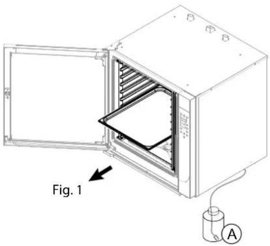
For models with washing, position the filter connected to the tube for collecting the detergent in the appropriate container (Fig. 1/A). 1/A).

The appliance must be cleaned with the coo-king compartment empty
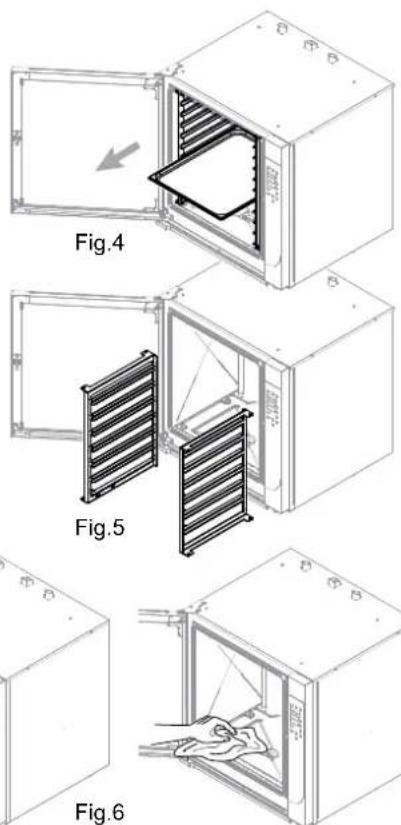
Open the door and remove the trays (if present) from the tray holder (Fig. 1). 1).
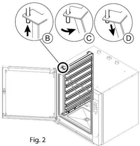
Remove the tray holding, removing it from the pins (Fig 2/B-C-D).
Depending on the model, for cooking compartment cleaning follow the instructions in paragraphs:
- Clean the cooking compartment with automatic washing. The oven will perform a cleaning cycle with the detergent and will complete the procedure by rinsing the cooking compartment.
- Clean the cooking compartment with manual washing. This procedure is used in ovens that do not have the automatic washing option.
9.3 AUTOMATIC WASHING
Start WASHING
Press "ENTER" (Fig 3/A) and "MENU" (Fig 3/C) to activate the main menu. Use the "MINUS" and "PLUS" keys (Fig 3/B) to select the WASH function. Press "ENTER" (Fig 3/A) to confirm.

The recommended washing cycle is displayed based on the amount of soiling (Fig. Display 2) 3 - Display 2)
FAST: brief washing cycle without detergent.
RINSE ONLY: complete washing cycle without detergent.
SHORT: brief washing cycle with one detergent cycle.
MEDIUM: complete washing cycle with two detergent cycles
LONG: complete washing cycle with three detergent cycles.
For example: Display 1 shows "WASH"
Display 2 shows "SHORT"
The "MINUS" and "PLUS" keys (Fig 3/B - Display 2) can be used to select the following washing cycles: FAST - ONLY RINSING - SHORT - MEDIUM - LONG Press "ENTER" (Fig 3/A) to start the cycle.
Stop WASHING
Before DETERGENT input
(Fig 3 - Display 2 - SOFTENING)
Press ENTER key (Fig 3/A) To continue washing press "ENTER" (Fig 3/A). To exit the function press "MENU" (Fig 3/C).
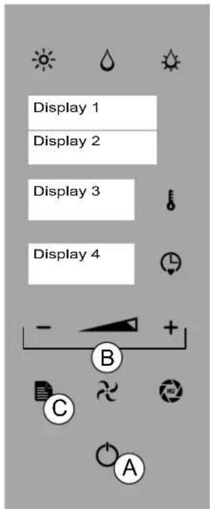
Fig.3
After you added the detergent (Fig. 3- Display 2-DETERGENT + WATER)
Press ENTER key (Fig 3/A)

ONLY CLEANING FUNCTION (the rest of the functions are disabled)
Possible actions: press the "enter" key to resume the interrupted wash or choose another type of washing using the MINUTS and PLUS keys (Fig. 3/B). Press"ENTER" (Fig 3/A) to start a new wash cycle.
9.4 MANUAL WASHING
The operator performs the washing and rinsing of the cooking compartment by applying liquid detergent during the cleaning procedure and drinking water during the rinsing procedure.

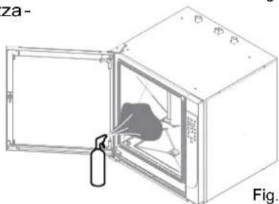
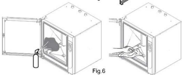
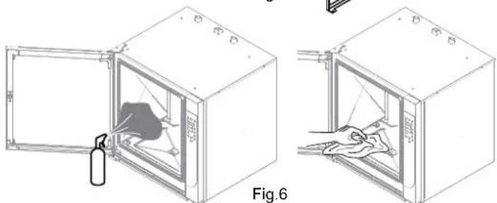
The appliance must be cleaned with the cooking compartment empty, without grills, trays or other accessories (Fig.4-5).
Set the STEAM cooking mode and TEMPERATURE parameters to 100°C and TIME to 20' (see CONVECTION (RISING)-STEAM-COMBI
When the operation is complete, open the door, allowing the cooking compartment to cook for a few seconds.
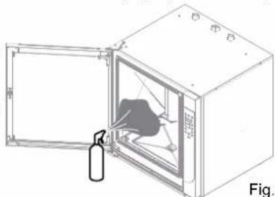
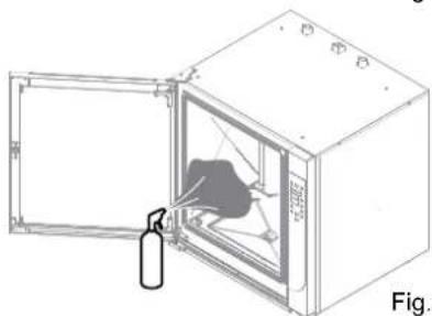
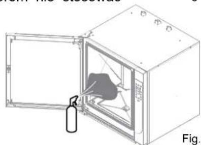
Apply using a regular steamer (Fig. 6) over the entire surface of the coo king chamber and manually thoroughly clean the entire surface using a non-abrasive sponge (Fig. 6).
When the operation is complete, rinse the coo-king compartment thoroughly with drinking water and never use jets of water under pressure.
Having successfully completed the operations described, carefully wipe the cooking chamber with a non-abrasive cloth.
If necessary, repeat the operations described above for a new cleaning cycle.
9.5 PERIODIC INSPECTIONS Cleaning the cooking compartment
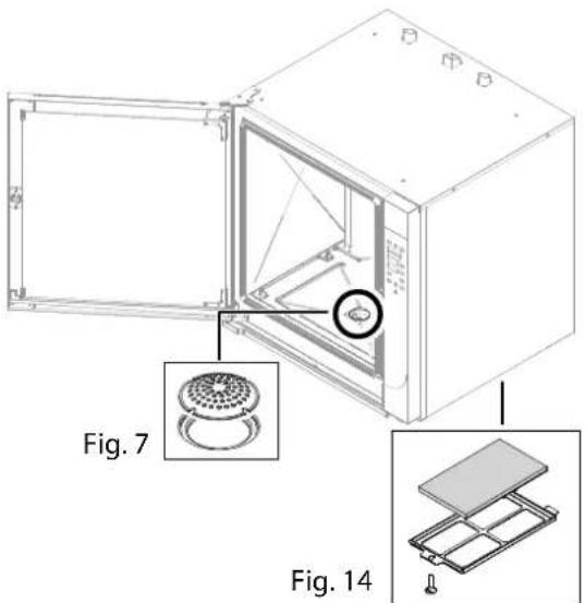
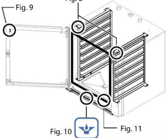
Inside the cooking compartment there could be various types of solid residue deposits. A visual inspection must be performed at the end of the day to see if this occurred. If so, manually remove these residues and, as needed, unscrew the filter from the base of the cooking compartment (Fig. 7) to free the drain of possible residues. When these operations are complete, replace the filter inside the cooking compartment.

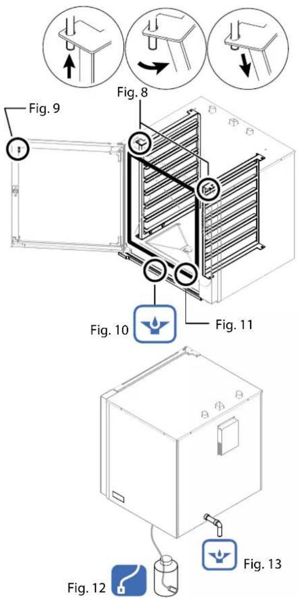
As necessary, remove the tray holders from the pin (Fig. 8) and remove them from the cooking compartment.
FILTER CLEANING
If necessary, remove the filter (fig. 14), wash with potable water and non-abrasive and/or corrosive material to eliminate possible solid residues. • Dry carefully. When these operations are complete, install the filter.

"Filter Cleaning" message (Display 2): carry out the routine maintenance of the filter. After cleaning press PLUS for 5 seconds to clear the message.
Cleaning the condensate drain pan
Inside the condensation collection tray there could be residue that obstruct the flow of liquids. A visual inspection is required at the end of the day to see if this has occurred. Manually remove these residues as needed to free the drainage hole (Fig. 10).
Cleaning the interior and exterior glass
The equipment has a fixed, glass attached to the door, and a mobile glass. If necessary and with the door completely open, remove the glass retainers (fig. 9) and carefully clean the glass from both sides. Before hooking it back to the door, carefully clean the fixed internal glass.
Inspection and cleaning of the door gas- sket
At the end of each washing of the cooking compartment and at the end of the daily cycle, thorough cleaning of the door gasket is needed for proper maintenance (Fig. 11).
Wash the gasket with non-abrasive and/or corrosive material, dry it thoroughly and spread vaseline (for food) over the surface to keep it soft and in good condition.
Checking the liquid detergent level
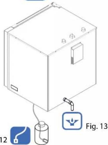
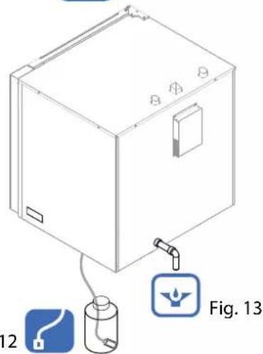
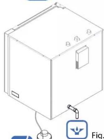
Appliances with automatic washing required a visual inspection at the end of the day to check the detergent in the special container (Fig. 12). 12
Make sure there is liquid detergent in the container and replace and/or refill as necessary. If there is no liquid detergent, the appliance does not report any anomaly and washing will be performed without detergent.
Check and clean the drains
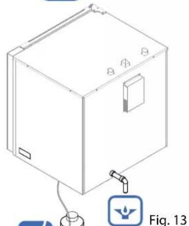
For correct disposal of the water in the drainage system, make sure that there are no obstructions or blockages of any kind along the entire line (Fig. 9-13).
10.1 List of alarms
Anomalies are shown on Display 2 during operation, see the description:
Chamber probe alarm: temperature probe broken or interrupted.
Humidity probe alarm: humidity probe broken or interrupted.
Internal core probe alarm: core probe broken or interrupted (it is possible to use the oven without probe in the core).
External core probe alarm: core probe broken or interrupted or not inserted correctly (it is possible to use the oven without probe in the core).
Board temperature alarm: board overheated (over 70°C).
Motor alarm: motor overheated.
No water alarm: insufficient water supply.
EEP: incorrect loading/updating software.
FLAM: no power flame.
Vent alarm: venting device malfunction.
OFFRUN alarm: fast temperature rise.
Pressing the "PLUS" button for 5 seconds may temporarily stop the alarm. The message will reoccur until resolution of the problem.

Contact the authorised service centre.
The authorised technician will identify the cause of the problem and restore proper operation.
TROUBLESHOOTING

Whenever the appliance does not work properly, try to solve the less serious problems using this table.
| ANOMALY POSSIBLE | CAUSE INTERVENTION | |
| The appliance does not turn on. | The master switch is not connected.The circuit breaker or magnetic circuit breaker has tripped | Connect the master switch.Reset the circuit breaker or magnetic circuit breaker |
| Steam is not being generated The water tap is closed Open the water tap | ||
| Water does not drain from the cooking compartment. | The drain is clogged. | Clean the drain filter.Free the drain from residues. |
| The inner walls are covered with limescale. | The water softener is not connected or is empty | Connect the appliance to a water softener.Regenerate the water softener.Descale the cooking compartment. |
| The cooking compartment is stained. | Water qualityIneffective detergent.Insufficient rinsing. | Filter the water (see water softener).Use the recommended detergent.Rinse once again. |
| The gas appliance will not turn on | Gas valve closed.Air in the hose | Open the gas valveRepeat the operation |
| No water The water tap is closed Open the water tap | ||
| Electronic components overheating (Alarm board temperature) | Cooling fans obstructed | Free the air passage or clean the filters |
| Filter cleaning message Filter maintenance timer exceeded | Proceed with cleaning (see 9.5 Periodic inspections) | |

If the problem cannot be resolved, turn the appliance off and shut all the supply valves. Then contact customer service.
Deactivation and scrapping of appliance

OBLIGATION OF DISPOSING OF MATERIALS USING THE LEGISLATIVE PROCEDURE IN FORCE IN THE COUNTRY WHERE THE APPLIANCE IS SCRAPPED.
PURSUANT TO the directives (see section no. 0.1) relating to the reduction of use of the hazardous substances in the electrical and electronic appliance and to the waste disposal. The symbol of the barred waste bin carried on the appliance or its packaging indicates that the product at the end of its useful life it must be disposed of separately from other waste.
Sorted waste disposal of products at the end of their useful life is organised and managed by the manufacturer. The user should dispose of this equipment contacting the manufacturer and following the system adopted by the latter to allow the separate collection of the equipment at the end of its service life. Appropriate separate collection for subsequent start-up of equipment assigned to recycling, treatment and disposal that is environmentally compatible contributes to avoiding possible negative effects on the environment and on health and promotes the reuse and/or recycling of the materials of which the equipment is composed. If the holder of this product disposes of it illegally, this involves the application of administrative sanctions provided by the laws in force.

Specialised personnel is in charge of deactivation and scrapping of the appliance.
Waste disposal

During operation and maintenance, do not disperse pollutants (oils, grease, etc.) into the environment and perform differentiated waste disposal depending on the composition of the different materials and in compliance with relevant laws in force.
Illegal waste disposal will be prosecuted by laws in force in the territory where the violation has been ascertained.
FOUR ELECTRONIQUE NUMERIQUE A ECRAN TACTILE - 2.0
MANUEL D'UTILISATION ET DE MAINTENANCE ORDINAIRE
FR

natural_image
Simple gray icon of a human figure inside a rounded square frame (no text or symbols)FORNO ELETTRICO
ELECTRIC OVEN
FOUR ELECTRIQUE
ELEKTROBACKOFEN
ELEKTRISCHE OVEN
FORNO ELÉTRICO
PIEKARNIK ELEKTRYCZNY
ELEKTROMOS SÜTÖ

FORNO A GAS
OVEN GAS
FOUR A GAZ
GASBACKOFEN
GASOVEN
FORNO A GÁS
PIEKARNIK GAZOWY
GÁZSÜTŐ


0. IDENTIFICATION DU DOCUMENT
0.1 TABLEAU NORMATIF DE REFERENCE
1. INFORMATIONS AUX UTILISATEURS
LE PRESENT MANUEL EST LA PROPRIETE DU FABRICANT ET TOUTE REPRODUCTION, MEME PARTIELLE, EST INTERDITE.
LE PRESENT MANUEL EST LA PROPRIETE DU FABRICANT ET TOUTE REPRODUCTION, MEME PARTIELLE, EST INTERDITE.

LE PRESENT MANUEL EST LA PROPRIETE DU FABRICANT ET TOUTE REPRODUCTION, MEME PARTIELLE, EST INTERDITE.
Démarrage RECETTE
LE PRESENT MANUEL EST LA PROPRIETE DU FABRICANT ET TOUTE REPRODUCTION, MEME PARTIELLE, EST INTERDITE.
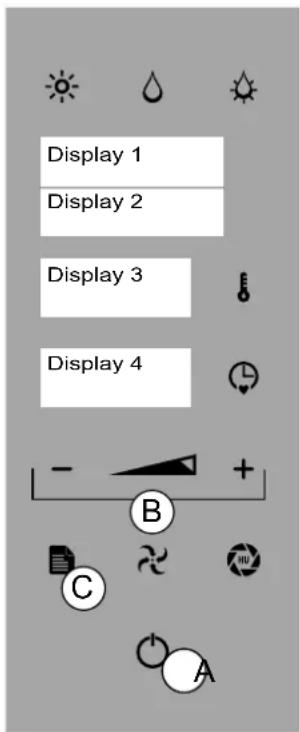
Fig.2
8.
CHARGEMENT ET DECHARGEMENT DU PRODUIT

CHARGEMENT DU PRODUIT
natural_image
Technical line drawing of an open industrial oven with internal components and a cylindrical component, labeled Fig. 1 (no text or symbols on the diagram itself)
natural_image
Technical diagram of an open oven with internal cooling duct and labeled component (A), no readable text or symbols beyond labels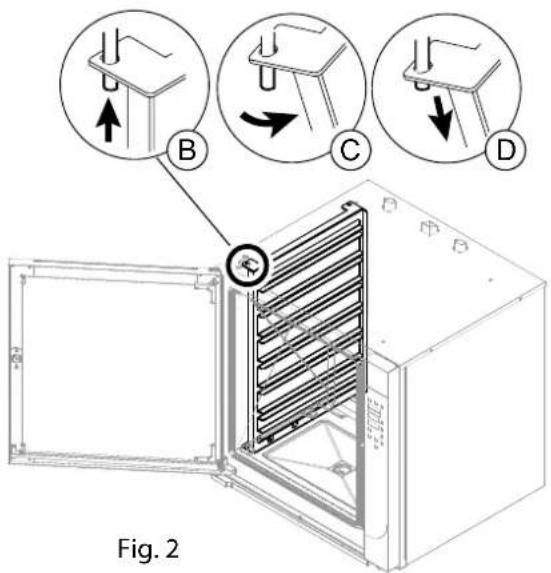
9.3 LAVAGE AUTOMATIQUE
Démarrage du LAVAGE
natural_image
Diagram of a fire extinguisher inside a cabinet, showing internal components and exhaust pipe (no text or labels)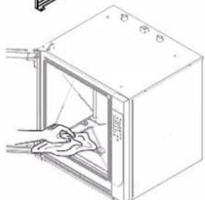
natural_image
Line drawing of a door with a cloth inside, showing hand cleaning the interior (no text or symbols)Fig.6
natural_image
Three circular diagrams showing mechanical assembly steps with arrows indicating direction (no text or symbols)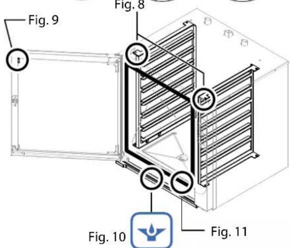
natural_image
Isometric line drawing of a rectangular industrial or laboratory device with mounting holes and a small icon labeled Fig. 13 (no text or symbols on the device itself)Fig. 12


LE PRESENT MANUEL EST LA PROPRIETE DU FABRICANT ET TOUTE REPRODUCTION, MEME PARTIELLE, EST INTERDITE.
natural_image
Simple gray icon of a human figure inside a rounded square frame (no text or symbols)FORNO ELETTRICO
ELECTRIC OVEN
FOUR ELECTRIQUE
ELEKTROBACKOFEN
ELEKTRISCHE OVEN
FORNO ELÉTRICO
PIEKARNIK ELEKTRYCZNY

FORNO A GAS
OVEN GAS
FOUR A GAZ
GASBACKOFEN
GASOVEN
FORNO A GÁS
PIEKARNIK GAZOWY


natural_image
Two diagrams showing a medical procedure: one with a needle inserted into a patient's mouth, the other with a crossed-out surgical tool (no text or symbols present)A - SONDA AL CORAZÓN (SINGLEPOINT, MULTIPOINT, AL VACÍO)
natural_image
Technical line drawing of an open industrial oven with internal cooling unit and cylindrical chamber (no text or symbols)
natural_image
Technical diagram of an oven with labeled components, showing internal structure and connection to a meter (no text or symbols beyond labels)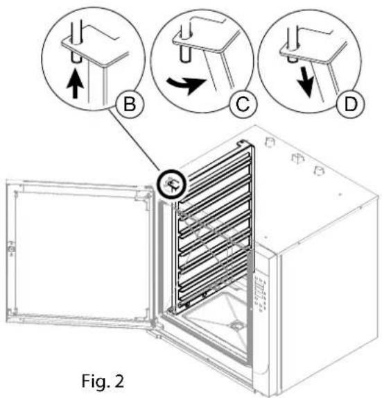
9.3 LAVADO AUTOMÁTICO
Inicio LAVADO
natural_image
Technical diagram of an open industrial oven with internal heating element, labeled Fig.4 (no text or symbols on the diagram itself)
natural_image
Technical line drawing of a microwave oven with two side slats, labeled Fig.5 (no text or symbols on the diagram itself)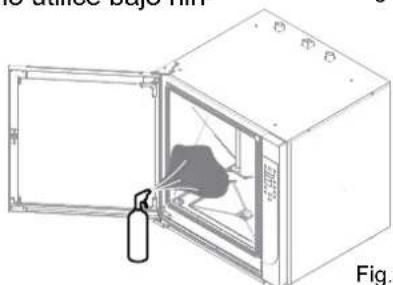
natural_image
Diagram of a fire extinguisher inside a large oven, showing internal components and exhaust pipe (no text or labels)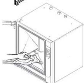
natural_image
Line drawing of a cabinet with an open door and cloth inside, showing hand cleaning (no text or symbols)Fig.6
9.5 VERIFICACIONES PERIÓDICAS A EFECTUAR
natural_image
Three circular diagrams showing mechanical assembly steps with arrows indicating direction (no text or symbols)Fig. 8

natural_image
Technical line drawing of a refrigerant cabinet with a water outlet and labeled component (no text or symbols beyond labels)Fig. 12
natural_image
Simple gray icon of a human figure inside a rounded square frame (no text or symbols)02/2019 - Ed. 6 - Cod.n° 184918
FORNO ELETTRICO
ELECTRIC OVEN
FOUR ELECTRIQUE
ELEKTROBACKOFEN
ELEKTRISCHE OVEN
FORNO ELÉTRICO
PIEKARNIK ELEKTRYCZNY
ELEKTROMOS SÜTÖ

FORNO A GAS
OVEN GAS
FOUR A GAZ
GASBACKOFEN
GASOVEN
FORNO A GÁS
PIEKARNIK GAZOWY
GÁZSÜTŐ


0. DOKUMENTKENNUNG
0.1 BEZUGSRAHMEN
1. ANWENDERINFORMATIONEN
natural_image
Technical line drawing of an open industrial oven with a cylindrical chamber inside, labeled 'Alp1.1' (no text or symbols on the diagram itself)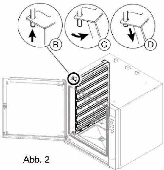
9.3 REINIGUNGAUTOMATIK
natural_image
Simple icon of a finger pressing a button, enclosed in a rounded square frame (no text or symbols)ELEKTRONISCHE DIGITALE OVEN TOUCH - 2.0
NL
HANDLEIDING VOOR GEBRUIK EN PERIODIEK ONDERHOUD

natural_image
Simple gray icon of a human figure inside a rounded square frame (no text or symbols)FORNO ELETTRICO
ELECTRIC OVEN
FOUR ELECTRIQUE
ELEKTROBACKOFEN
ELEKTRISCHE OVEN
FORNO ELÉTRICO
PIEKARNIK ELEKTRYCZNY
ELEKTROMOS SÜTÖ

FORNO A GAS
OVEN GAS
FOUR A GAZ
GASBACKOFEN
GASOVEN
FORNO A GÁS
PIEKARNIK GAZOWY
GÁZSÜTŐ


0. DOCUMENTIDENTIFICATIE
0.1 REFERENTIEKADER REGELGEVING
1. INFORMATIE VOOR DE GEBRUIKERS



BCD
Display 3 toont "ITA"
natural_image
Two diagrams showing a medical procedure: one with a needle inserted into a patient's mouth, the other with a crossed-out surgical tool (no text or symbols present)A - KERNSONDE (SINGLEPOINT, MULTIPOINT, VACUÜM)
Display 4 toont "I 50"
Display 3 toont "RUNNING"
Display 2 toont "SAVE"
Display 3 toont "RUNNING"
natural_image
Technical line drawing of an open industrial oven with internal components and a cylindrical component, labeled Fig. 1 (no text or symbols on the diagram itself)
"Heterogene" Operator
natural_image
Technical diagram of an oven with labeled components, showing internal structure and connection to a meter (no text or symbols beyond labels)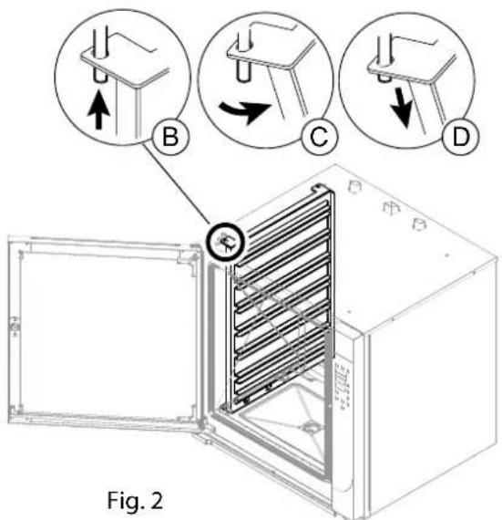
natural_image
Diagram of a fire extinguisher inside a water tank, showing internal components and exhaust pipe (no text or labels)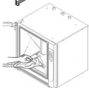
natural_image
Line drawing of a cabinet with an open door and cloth inside, showing hand cleaning (no text or symbols)Fig.6
natural_image
Diagram of a refrigerant unit with labeled components (Fig. 12 and Fig. 13), showing internal components connected to a piping bag (no text or symbols on the diagram itself)natural_image
Simple icon of a finger pressing a button, enclosed in a rounded square frame (no text or symbols)
FORNO ELETRÓNICO DIGITAL TOUCH - 2.0
natural_image
Two diagrams showing a tool on a surface and a crossed-out tool on a surface, both without any text or symbols.A - SENSOR DE NÚCLEO (SINGLEPOINT, MULTIPOINT, VÁCUO)
Display 3 exibe "60"
Display 4 exibe "I 50"
Display 3 exibe "RUNNING"
Display 2 exibe "SAVE"
Display 3 exibe "RUNNING"
natural_image
Technical line drawing of an open industrial oven with internal cooling unit and cylindrical chamber (no text or symbols)| MOD. CME 4 | CME/CMFE CYE 6 | CME/CMFE CYE 10 | CMG/CMFG CYG 6 | CMG/CMFG CYG 10 | CME/CMFE CYE 102 | |
| Q.tà carico forno/Oven load cap/Q.té chargement four/Capacidade max (kg) | 12 | 18 | 30 | 18 | 30 | 50 |
9.1 LIMPEZA DO APARELHO
Avisos gerais
natural_image
Technical diagram of an oven with labeled components, showing internal structure and connection to a meter (no text or symbols beyond labels)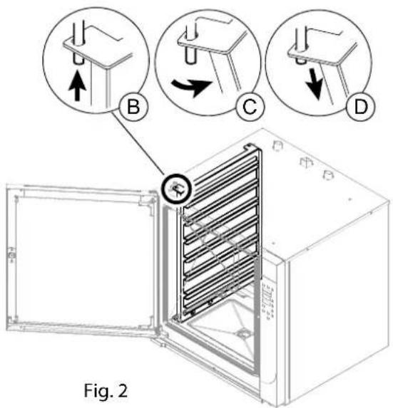
9.3 LAVAGEM AUTOMÁTICA
Início LAVAGEM
natural_image
Two technical diagrams showing a fire extinguisher inside a cabinet, with no visible text or symbols.O FABRICANTE DETÊM OS DIREITOS DE PROPRIEDADE INTELECTUAL DO PRESENTE MANUAL, SENDO PROIBIDA A SUA REPRODUÇÃO, TOTAL OU PARCIAL.
9.5 VERIFICAÇÕES PERIÓDICAS A EFETUAR Limpeza do compartimento de cozedura
natural_image
Three circular diagrams showing mechanical assembly steps with arrows indicating direction (no text or symbols)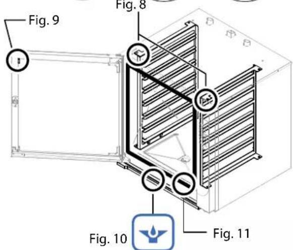
natural_image
Technical line drawing of a rectangular enclosure with internal components and a labeled diagram (Fig. 13), no readable text or symbols beyond labels.Fig. 12
natural_image
Simple icon of a finger pressing a button, enclosed in a rounded square frame (no text or symbols)
CYFROWY PIEKARNIK ELEKTRYCZNY TOUCH - 2.0 INSTRUKCJA OBSŁUGI I KONSERWACJI ZWYCZAJNEJ
PL
0. IDENTYFIKACJA DOKUMENTU
0.1 RAMY REGULACYJNE ODNIESIENIA
1. INFORMACJE DLA UŻYTKOWNIKÓW
natural_image
Technical line drawing of an open industrial oven with internal components and a cylindrical chamber (no text or symbols)9.1 CZYSZCZENIE URZĄDZENIA
Uwagi ogólne

natural_image
Technical diagram of an oven with labeled component 'Fig. 1' and connection point A (no text or symbols beyond labels)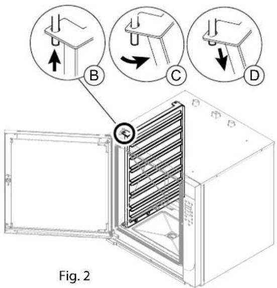
9.3 MYCIE AUTOMATYCZNE
Uruchomienie MYCIA
natural_image
Diagram of a fire extinguisher inside an open oven, showing internal components and exhaust air (no text or labels)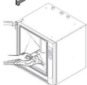
natural_image
Line drawing of a door with an open lid and hand placed inside (no text or symbols)Fig.6
natural_image
Three circular diagrams showing mechanical assembly steps with arrows indicating direction (no text or symbols)Fig. 8
natural_image
Line drawing of a rectangular appliance with internal components and a small icon below (no text or symbols)Fig. 12
Fig. 13
10.1 Spis alarmów
natural_image
Gray icon of a finger pressing a button, enclosed in a rounded square frame (no text or symbols)
TOUCH - 2.0 DIGITÁLIS ELEKTRONIKUS SÜTŐ HASZNÁLATI ÉS ÁLTALÁNOS KARBANTARTÁSI KÉZIKÖNYV
HU
02/2019 - Ed. 6 - Cod.n° 184918
FORNO ELETTRICO
ELECTRIC OVEN
FOUR ELECTRIQUE
ELEKTROBACKOFEN
ELEKTRISCHE OVEN
FORNO ELÉTRICO
PIEKARNIK ELEKTRYCZNY
ELEKTROMOS SÜTÖ

FORNO A GAS
OVEN GAS
FOUR A GAZ
GASBACKOFEN
GASOVEN
FORNO A GÁS
PIEKARNIK GAZOWY
GÁZSÜTŐ


0. A DOKUMENTUM AZONOSÍTÁSA
0.1 VONATKOZÓ JOGSZABÁLYI HÁTTÉR
1. TÁJÉKOZTATÓ A FELHASZNÁLÓK RÉSZÉRE



BCD
natural_image
Two diagrams showing a medical procedure: one with a needle inserted into a patient's abdomen, the other with a crossed-out surgical tool (no text or symbols present)A - MAGHÔMÉRŐ (SINGLEPOINT, MULTIPOINT, SOUSVIDE)
natural_image
Technical line drawing of an open industrial oven with internal components and a cylindrical chamber (no text or symbols)natural_image
Technical diagram of an oven with labeled part 'Fig. 1' and connection point 'A' (no text or symbols beyond labels)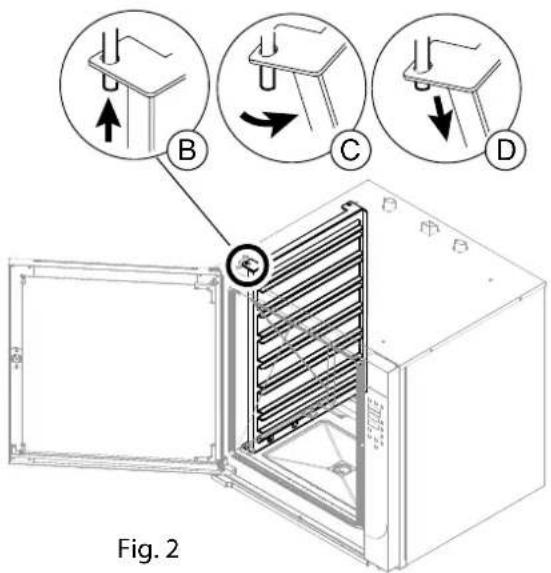

natural_image
Diagram of a fire extinguisher inside an open safety cabinet, showing internal components and exhaust pipe (no text or labels)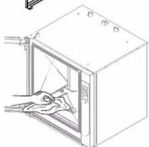
natural_image
Line drawing of a cabinet with an open door and a cloth inside, showing internal components (no text or symbols)Fig.6
natural_image
Isometric line drawing of a refrigerant cabinet with labeled components (Fig. 12 and Fig. 13), no text or symbols on the diagram itself.natural_image
Simple icon of a finger pressing a button, enclosed in a rounded square frame (no text or symbols)
DIGITAL ELEKTRISK OVN TOUCH - 2.0
VEJLEDNING FOR BRUG OG ALMINDELIG VEDLIGEHOLDELSE
DA
FORNO ELETTRICO
ELECTRIC OVEN
FOUR ELECTRIQUE
ELEKTROBACKOFEN
ELEKTRISCHE OVEN
FORNO ELÉTRICO
PIEKARNIK ELEKTRYCZNY
ELEKTROMOS SÜTÖ
ELEKTRISK OVN

FORNO A GAS
OVEN GAS
FOUR A GAZ
GASBACKOFEN
GASOVEN
FORNO A GÁS
PIEKARNIK GAZOWY
GÁZSÜTŐ
GAS OVN


0. IDENTIFIKATION DOKUMENT
0.1 NORMATIV REFERENCERAMME
1. INFORMATION TIL BRUGERNE
5.2 INDSTILLING AF TEMPERATUREN
7.1 OPSKRIFTMAPPE Gem OPSKRIFT
ILÆGNING AF PRODUKTET
UDTAGNING AF PRODUKTET
natural_image
Technical line drawing of an open industrial oven with internal cooling unit and cylindrical chamber (no text or symbols)9.1 VASKER AF APPARATET Generelle advarsler

natural_image
Technical diagram of an open oven with internal heating element and labeled component (A), no text or symbols present.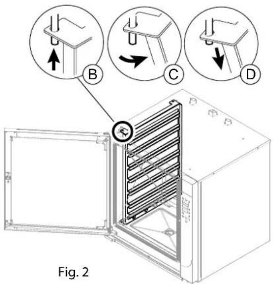
9.3 Automatisk VASKER Start VASKER
natural_image
Two technical diagrams showing a fire extinguisher inside a cabinet, with no visible text or symbols.9.5 PERIODISKE KONTROLINDGREB DER SKAL UDF∅RES VASKER af ovnrummet
natural_image
Isometric line drawing of a refrigerant unit with labeled components (Fig. 12 and Fig. 13), no text or symbols on the diagram itself.10.1 Alarmliste
- A - SONDA AL CUORE (SINGLEPOINT, MULTIPOINT, SOTTOVUOTO)
- LAVAGGIO AUTOMATICO
- Avvio LAVAGGIO
- DOCUMENT IDENTIFICATION
- REFERENCE STANDARDS
- INFORMATION FOR USERS
- GENERAL SAFETY INFORMATION
- OPERATING FUNCTIONS
- COMMISSIONING
- OPERATING PARAMETERS
- COOKING PARAMETERS
- PROGRAMMING
- LOADING AND UNLOADING THE PRODUCT
- ROUTINE MAINTENANCE
- ALARM SIGNALS
- DISPOSAL
- Introduction
- Scope of the document
- How to read the document
- Keeping the document
- Addressees
- Operator training program
- Pre-arrangements depending on customer
- Intended use
- Allowed operating conditions
- Test inspection and warranty
- The warranty terminates in case of:
- Authorisation
- Description of pictograms
- DANGER
- PROHIBITIONS
- OBLIGATION
- Individual general protection measures to be adopted
- Information plates on the appliance
- Indications concerning residual risks
- What to do when there is a gas odour in the area
- Mode and function of buttons
- Control panel operation
- Description of the operating modes
- Software language setup
- Description of stop modes
- Emergency stop
- Restarting:
- Stoppage during a work phase
- Stop due to opening the door during operation
- Commissioning
- Cleaning at commissioning
- Daily activation
- Procedure:
- Daily and prolonged deactivation
- Starting production
- Turning-on/Turning-off
- To proceed with shutdown:
- DATE/CLOCK
- SETTING THE TEMPERATURE
- SETTING THE TIME
- MOISTURE SETUP
- SETTING THE VENT (CONVECTIONonly)
- SETTING THE FAN SPEED
- SETTING THE PREHEATING
- SETTING FAST COOLING
- SETTING THE PROGRAMMED START (POSTPONEMENT)
- CONVECTION (RISING)- STEAM - COMBI
- PROVING
- CORE PROBE AND DELTA T
- A - CORE PROBE (SINGLEPOINT, MULTIPOINT, VACUUM)
- B - DELTA T
- C - DUAL CORE PROBE (SINGLEPOINT, MULTIPOINT, UNDER VA-CUUM)
- Recipe Index
- Save Recipe
- Modify RECIPE
- DELETE PHASE
- Start RECIPE
- Delete RECIPE
- USB DEVICE
- Uploading RECIPES
- Downloading RECIPES
- 8.
- LOADING AND UNLOADING THE PRODUCT
- LOADING THE PRODUCT
- UNLOADING THE PRODUCT
- CLEANING THE APPLIANCE - General remarks
- Summary table: qualification-intervention-frequency
- Generic operator
- Homogeneous operator
- CLEANING AT COMMISSIONING
- AUTOMATIC WASHING
- Start WASHING
- Stop WASHING
- Before DETERGENT input
- (Fig 3 - Display 2 - SOFTENING)
- ONLY CLEANING FUNCTION (the rest of the functions are disabled)
- MANUAL WASHING
- PERIODIC INSPECTIONS Cleaning the cooking compartment
- FILTER CLEANING
- Cleaning the condensate drain pan
- Cleaning the interior and exterior glass
- Inspection and cleaning of the door gas- sket
- Checking the liquid detergent level
- Check and clean the drains
- List of alarms
- TROUBLESHOOTING
- Deactivation and scrapping of appliance
- Waste disposal
- IDENTIFICATION DU DOCUMENT
- TABLEAU NORMATIF DE REFERENCE
- INFORMATIONS AUX UTILISATEURS
- Démarrage RECETTE
- CHARGEMENT ET DECHARGEMENT DU PRODUIT
- CHARGEMENT DU PRODUIT
- LAVAGE AUTOMATIQUE
- Démarrage du LAVAGE
- A - SONDA AL CORAZÓN (SINGLEPOINT, MULTIPOINT, AL VACÍO)
- LAVADO AUTOMÁTICO
- Inicio LAVADO
- VERIFICACIONES PERIÓDICAS A EFECTUAR
- DOKUMENTKENNUNG
- BEZUGSRAHMEN
- ANWENDERINFORMATIONEN
- REINIGUNGAUTOMATIK
- DOCUMENTIDENTIFICATIE
- REFERENTIEKADER REGELGEVING
- INFORMATIE VOOR DE GEBRUIKERS
- A - KERNSONDE (SINGLEPOINT, MULTIPOINT, VACUÜM)
- "Heterogene" Operator
- A - SENSOR DE NÚCLEO (SINGLEPOINT, MULTIPOINT, VÁCUO)
- LIMPEZA DO APARELHO
- Avisos gerais
- LAVAGEM AUTOMÁTICA
- Início LAVAGEM
- VERIFICAÇÕES PERIÓDICAS A EFETUAR Limpeza do compartimento de cozedura
- IDENTYFIKACJA DOKUMENTU
- RAMY REGULACYJNE ODNIESIENIA
- INFORMACJE DLA UŻYTKOWNIKÓW
- CZYSZCZENIE URZĄDZENIA
- Uwagi ogólne
- MYCIE AUTOMATYCZNE
- Uruchomienie MYCIA
- Spis alarmów
- A DOKUMENTUM AZONOSÍTÁSA
- VONATKOZÓ JOGSZABÁLYI HÁTTÉR
- TÁJÉKOZTATÓ A FELHASZNÁLÓK RÉSZÉRE
- A - MAGHÔMÉRŐ (SINGLEPOINT, MULTIPOINT, SOUSVIDE)
- IDENTIFIKATION DOKUMENT
- NORMATIV REFERENCERAMME
- INFORMATION TIL BRUGERNE
- INDSTILLING AF TEMPERATUREN
- OPSKRIFTMAPPE Gem OPSKRIFT
- ILÆGNING AF PRODUKTET
- UDTAGNING AF PRODUKTET
- VASKER AF APPARATET Generelle advarsler
- Automatisk VASKER Start VASKER
- PERIODISKE KONTROLINDGREB DER SKAL UDF∅RES VASKER af ovnrummet
- Alarmliste
Brand : MBM
Model : CME102
Category : Pizza oven