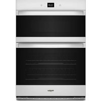
WOEC5027LW - Electric oven WHIRLPOOL - Free user manual and instructions
Find the device manual for free WOEC5027LW WHIRLPOOL in PDF.


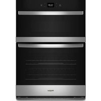
| Product type | Built-in electric oven |
| Brand | Whirlpool |
| Model | WOEC5027LW |
| Dimensions (H x W x D) | 73.6 cm x 75.6 cm x 59.1 cm |
| Weight | 91 kg (200 lb) |
| Power supply | 240 V, 7.3-9.6 kW, 40 A circuit |
| Capacity | Single oven, standard capacity |
| Cooking modes | Bake, broil, air fry (depending on model) |
| Self-cleaning | Pyrolytic and steam cleaning (Steam Clean) |
| Connectivity | Wi-Fi (2.4 GHz), Whirlpool app |
| Safety | Door lock, automatic shut-off, child lock |
| Material | Stainless steel and porcelain enamel |
| Racks | SatinGlide sliding racks (depending on model) |
| Interior light | Oven light (does not work during self-cleaning) |
| Spare parts | Certified Whirlpool parts available |
| Repairability | By qualified technician |
| Installation | Built-in, requires opening in cabinet |
| Number of pages in manual | 72 pages |
Frequently Asked Questions - WOEC5027LW WHIRLPOOL
User questions about WOEC5027LW WHIRLPOOL
0 question about this device. Answer the ones you know or ask your own.
Ask a new question about this device
Download the instructions for your Electric oven in PDF format for free! Find your manual WOEC5027LW - WHIRLPOOL and take your electronic device back in hand. On this page are published all the documents necessary for the use of your device. WOEC5027LW by WHIRLPOOL.
USER MANUAL WOEC5027LW WHIRLPOOL
BUILT-IN ELECTRIC SINGLE AND DOUBLE OVEN OWNER'S MANUAL
OWNER'S MANUAL FOR BUILT-IN ELECTRIC SINGLE OR DOUBLE OVEN
OWNER'S MANUAL FOR BUILT-IN ELECTRIC SINGLE OR DOUBLE OVEN
Table of Contents
BUILT-IN OVEN SAFETY....2 Built-In Oven Safety ....2
OVEN MAINTENANCE AND CARE ....4 General Cleaning....4 Self-Cleaning Cycle....5 Steam Clean (on some models) ....6
INSTALLATION INSTRUCTIONS .....6
REQUIREMENTS....6 Tools and Parts ....6 Location Requirements ....7 Electrical Requirements .... 12
INSTALLATIONS .... 13 Prepare Built-In Oven .... 13 Remove Oven Door(s) .... 13 Positioning Oven Feet for Multiple Cabinet Cutout Heights .... 14 Make Electrical Connection.... 18 Install Oven .... 19 Install Deflector Kit (on some models) .... 20 Replace Oven Door(s) .... 21 Complete Installation .... 22
BUILT-IN OVEN SAFETY
Your safety and the safety of others are very important.
We have provided many important safety messages in this manual and on your appliance. Always read and obey all safety messages.

This is the safety alert symbol.
This symbol alerts you to potential hazards that can kill or hurt you and others.
All safety messages will follow the safety alert symbol and either the word "DANGER" or "WARNING." These words mean:
DANGER
WARNING
You can be killed or seriously injured if you don't immediately follow instructions.
You can be killed or seriously injured if you don't follow instructions.
All safety messages will tell you what the potential hazard is, tell you how to reduce the chance of injury, and tell you what can happen if the instructions are not followed.
IMPORTANT SAFETY INSTRUCTIONS
WARNING: To reduce the risk of fire, electric shock, or injury to persons when using the appliance, follow basic precautions, including the following:
Proper Installation - The appliance, when installed, must be electrically grounded in accordance with local codes, or in the absence of local codes, with the National Electrical Code, ANSI/NFPA 70 or the Canadian Electrical Code, CSA C22.1-02. In Canada, the appliance must be electrically grounded in accordance with Canadian Electrical Code. Be sure your appliance is properly installed and grounded by a qualified technician.
Never Use Your Appliance for Warming or Heating the Room.
Do Not Leave Children Alone - Children should not be left alone or unattended in area where appliance is in use. They should never be allowed to sit or stand on any part the appliance.
Wear Proper Apparel – Loose-fitting or hanging garments should never be worn while using the appliance.
User Servicing – Do not repair or replace any part of the appliance unless specifically recommended in the manual. All other servicing should be referred to a qualified technician.
Storage in or on Appliance – Flammable materials should not be stored in an oven or near surface units.
This appliance is not intended for storage.
Do Not Use Water on Grease Fires – Smother fire or flame or use dry chemical or foam-type extinguisher.
Do not use replacement parts that have not been recommended by the manufacturer (e.g., parts made at home using a 3D printer).
■ Use Only Dry Potholders – Moist or damp potholders on hot surfaces may result in burns from steam. Do not let potholder touch hot heating elements. Do not use a towel or other bulky cloth.
■ Use Care When Opening Door – Let hot air or steam escape before removing or replacing food.
■ DO NOT TOUCH HEATING ELEMENTS OR INTERIOR SURFACES OF OVEN – Heating elements may be hot even though they are dark in color. Interior surfaces of an oven become hot enough to cause burns. During and after use, do not touch, or let clothing or other flammable materials contact heating elements or interior surfaces of oven until they have had sufficient time to cool. Other surfaces of the appliance may become hot enough to cause burns – among these surfaces are the coil and cooktop elements, oven vent openings and surfaces near these openings, oven doors, and windows of oven doors.
■ Do Not Heat Unopened Food Containers – Build-up of pressure may cause container to burst and result in injury.
- Keep Oven Vent Ducts Unobstructed.
SAVE THESE INSTRUCTIONS
IMPORTANT SAFETY INSTRUCTIONS
WARNING: To reduce the risk of fire, electric shock, or injury to persons when using the appliance, follow basic precautions, including the following:
- CAUTION: DO NOT LEAVE FOOD OR COOKING UTENSILS, ETC., IN OVEN DURING THE PYROLYTIC SELF-CLEANING MODE OF OPERATION. Placement of Oven Racks – Always place oven racks in desired location while oven is cool. If rack must be moved while oven is hot, do not let potholder contact hot heating element in oven.
■ Before Self-Cleaning the Oven – Remove broiler pan and other utensils, and wipe off all excessive spillage.
For self-cleaning ovens:
- Do Not Clean Door Gasket – The door gasket is essential for smart enabled ranges and ovens: for a good seal. Care should be taken not to rub, damage or move the gasket. ■ Do not use a protective coating to line the oven and do not use commercial oven cleaner unless Certified for use in a self-cleaning oven. ■ Clean Only Parts Listed. Remote Operation - This appliance is configurable to allow remote operation at any time. Do not store any flammable materials or temperature sensitive items inside, on top or near surface units of the appliance.
SAVE THESE INSTRUCTIONS
Internet Connectivity Guide for Connected Appliances Only
IMPORTANT: Proper installation of your appliance prior to use is your responsibility. Be sure to read and follow the installation instructions that came with your appliance.
Connectivity requires Wi-Fi and account creation. App features and functionality are subject to change. Data rates may apply. Once installed, launch the app. You will be guided through the steps to set up a user account and to connect your appliance.
You Will Need:
A home wireless router supporting Wi-Fi, 2.4 GHz with WPA2 security. If you are unsure of your router's capabilities, refer to the router manufacturer's instructions. The router must be on and have a live internet connection. The 10-character SAID code for your appliance. The SAID code is either printed on a label on the appliance or found on the LCD screen.
Federal Communications Commission (FCC) Compliance Notice
This device complies with Part 15 of the FCC Rules. Operation is subject to the following two conditions:
- This device may not cause harmful interference, and
- This device must accept any interference received, including interference that may cause undesired operation. Changes or modifications not expressly approved by the party responsible for compliance could void the user's authority to operate the equipment.
Industry Canada (IC) Compliance Notice
This Device complies with Industry Canada licence-exempt RSS standard(s). Operation is subject to the following two conditions:
- This device may not cause interference.
- This device must accept any interference, including interference that may cause undesired operation of the device.
Under Industry Canada regulations, this radio transmitter may only operate using an antenna of a type and maximum (or lesser) gain approved for the transmitter by Industry Canada. To reduce potential radio interference to other users, the antenna type and its gain should be so chosen that the equivalent isotropically radiated power (e.i.r.p.) is not more than that necessary for successful communication.
To comply with FCC and Industry Canada RF radiation exposure limits for general population, antenna(s) used for this transmitter must be installed such that a minimum separation distance of 20 cm is maintained between the radiator (antenna) and all persons at all times and must not be co-located or operating in conjunction with any other antenna or transmitter.
If this equipment does cause harmful interference to radio or television reception, which can be determined by turning the equipment off and on, the user is encouraged to try to correct the interference by one of the following measures:
■ Reorient or relocate the receiving antenna. ■ Connect the equipment into an outlet on a circuit different from that to which the receiver is connected. ■ Increase the separation between the equipment and receiver.
■ Consult the dealer or an experienced radio/TV technician for help.
IMPORTANT: Before cleaning, make sure all controls are OFF and the oven is cool. Always follow label instructions on cleaning products.
Soap, water, and a soft cloth or sponge are suggested first unless otherwise noted.
EXTERIOR PORCELAIN ENAMEL SURFACES (on some models)
Food spills containing acids, such as vinegar and tomato, should be cleaned as soon as the entire oven is cool. These spills can affect the finish.
Cleaning Method:
■ Glass cleaner, mild liquid cleaner, or nonabrasive scrubbing pad: Gently clean around the model/serial/rating plate because scrubbing may remove numbers. ■ Affresh®+Kitchen and Appliance Cleaner Part Number W10355010 (not included): See the Quick Start Guide for ordering information.
STAINLESS STEEL (on some models)
NOTE: To avoid damage to stainless steel surfaces, do not use soap-filled scouring pads, abrasive cleaners, steel-wool pads, gritty washcloths, or abrasive paper towels. Damage may occur to stainless steel surfaces, even with one-time or limited use.
Cleaning Method:
Rub in direction of grain to avoid damaging.
■ Affresh®+ Stainless Steel Cleaner Part Number W10355016 (not included):
See the Quick Start Guide for ordering information.
STAINLESS STEEL AND BLACK STAINLESS STEEL (on some models)
To avoid damage to stainless steel or black stainless steel surfaces, do not use soap-filled scouring pads, abrasive clear cooktop cleaners, steel-wool pads, gritty washcloths, or abrasive paper towels.
Cleaning Method:
Rub in the direction of the grain to avoid damaging.
■ Affresh® Stainless Steel Cleaner Part Number W10355016 (not included) or Affresh® Stainless Steel Cleaning Wipes Part Number W10355049 (not included):
See the Quick Start Guide for ordering information.
METALLIC PAINT (on some models)
Do not use abrasive cleaners, cleaners with bleach, rust removers, ammonia, or sodium hydroxide (lye) because the paint surface may stain.
CONTROL PANEL AND OVEN DOOR EXTERIOR
To avoid damage to the control panel, do not use abrasive cleaners, steel-wool pads, gritty washcloths, or abrasive paper towels.
Cleaning Method:
■ Glass cleaner and soft cloth or sponge:
Apply glass cleaner to a soft cloth or sponge, not directly on the panel.
■ Affresh® Kitchen and Appliance Cleaner Part Number W10355010 (not included): See the Quick Start Guide for ordering information.
NOTE: To clean the trough, the oven door must be removed first. See the "Oven Door" section.
OVEN RACKS
unless Cleaning Method:
■ Steel-wool pad.
■ For racks that have discolored and are harder to slide, a light coating of vegetable oil applied to the rack guides will help.
AIR FRY BASKET (on some models)
NOTE: Rinse off basket with soap and water before first use.
Cleaning Method:
■ Dishwasher safe. If discoloration occurs, soak the air fry basket in a 50/50 solution of a calcium, lime, rust remover product and water for 4-5 minutes and repeat as necessary. Once complete, wash the basket with soap and water before use.
OVEN CAVITY OVEN DOOR INTERIOR
Do not use oven cleaners.
Food spills should be cleaned after the oven cools. At high temperatures, foods react with porcelain, and staining, etching, pitting, or faint white spots can result.
Cleaning Method:
■ Self-Cleaning cycle:
See the "Self-Cleaning Cycle" section first. Remove racks or they will discolor and become harder to slide. If this happens, a light coating of vegetable oil applied to the rack guides will help them slide.
■ For optimal door cleaning results, wipe away any deposits with a damp sponge before running cycle.
+POWERED ATTACHMENTS (on some models)
To avoid damage to the nonstick surfaces, do not use abrasive cleaners, steel-wool pads, gritty washcloths, or abrasive paper towels. Food spills should be cleaned when the +Powered Attachment cools.
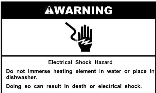
Do not soak or immerse the Heating Element.
†affresh® is a registered trademark of Whirlpool, U.S.A.
Cleaning Method:
Soap, water, and a soft cloth or sponge: Wipe the Heating Element when it is cool. All attachments can be cleaned with soap, water, and a soft cloth or sponge. ■ Dishwasher: The Base Pan, +Grill Attachment, +Baking Stone Attachment, and +Steamer Attachment are dishwasher-safe. ■ Affresh® Cooktop Cleaner: Stubborn soils on the +Baking Stone Attachment can be cleaned with baking soda and a scratch heavy duty scrub sponge. Rub cream into surface with a damp paper towel or soft cloth. Continue rubbing until film disappears.
See the Smart Oven+ Powered Attachments User Instructions for more detailed instructions.
Self-Cleaning Cycle
WARNING
Burn Hazard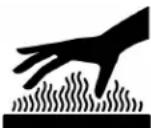
Do not touch the oven during the Self-Cleaning cycle. Keep children away from the oven during Self-Cleaning cycle.
Failure to follow these instructions can result in burns.
IMPORTANT: The health of some birds is extremely sensitive to the fumes given off during the Self-Cleaning cycle. Exposure to the fumes may result in death to certain birds. Always move birds to another closed and well-ventilated room.
Self-clean the oven before it becomes heavily soiled. Heavy soil results in longer cleaning and more smoke.
Keep the kitchen well-ventilated during the Self-Cleaning cycle to help get rid of heat, odors, and smoke.
Do not block the oven vent(s) during the Self-Cleaning cycle; the oven must be able to move freely. See the "Oven Vents" section. Do not clean, rub, damage, or move the oven door gasket. The door gasket is essential for a good seal.
Prepare Oven:
Remove the broiler pan, grid, cookware and bakeware, and, on some models, the temperature probe from the oven. Remove oven racks to keep them shiny and easy to slide. See the "General Cleaning" section for more information. Remove any foil from the oven because it may burn or damage the oven.
Hand clean inside door edge and 1½ inches (3.8 cm) area around the inside oven cavity frame, being certain not to rub or bend the gasket. This area does not get hot enough during high-temp self-cleaning to remove soil. Do not let water, cleaner, etc., enter slots on door frame. Use a damp cloth to clean this area.
Wipe out any loose soil to reduce smoke and avoid damage. At high temperatures, foods react with porcelain. Staining, etching, pitting, or faint white spots can result. This is not a defect and will not affect cooking performance.
IMPORTANT:
Oven temperature must be below 500°F (260°C) to program a self-clean cycle. For double ovens only: Only 1 oven can be cleaned at a time. For double ovens only: Both oven doors will lock when either oven is running the Self-Cleaning cycle.
How the Cycle Works
IMPORTANT: The heating and cooling of porcelain on steel in the oven may result in discoloring, loss of gloss, hairline cracks, and popping sounds.
The Self-Cleaning cycle uses very high temperatures, burning soil to a powdery ash.
NOTE: 12 hours must pass before the next Self-Clean can begin. Once the oven has completely cooled, remove ash with a damp cloth. To avoid breaking the glass, do not apply a cool damp cloth to the inner door glass before it has completely cooled.
The oven lights will not work during the Self-Cleaning cycle.
NOTE: The oven has a two-speed cooling fan motor. During the Self-Cleaning cycle, the fan(s) will operate at its highest speed to increase airflow to better exhaust the hotter air through the oven vent(s). An increase in noise may be noticeable during and after the Self-Cleaning cycle until the oven cools.
Before Self-Cleaning, make sure the door is closed completely or it will not lock and the cycle will not begin. When the oven is locked, the doors of the oven cannot be opened. To avoid damage to the doors, do not force the doors open when the oven is locked.
To Self-Clean:
NOTE: For specific instructions on your model's Self-Clean cycle, please see your model's online Control Guide.
- Close the door, and (for select models) touch the Tools keypad. Select the Self-Clean icon. (For Double Ovens) Select Upper Cavity or Lower Cavity. On some models, select the "1" or "2" number keypad to select the desired oven to clean.
- Select the duration or level of cleaning. This will impact the duration, which can range from 3 to 6 hours including cool down. If this model offers "Steam Clean," please check the "Steam Clean" section.
- (On select models) follow the prompts on the oven display to prepare the oven.
- Select Start OR (on select models) select Delay Start to set a delayed Self-Cleaning cycle. See the "To Delay Start Self-Cleaning Cycle" section. The oven doors will automatically lock.
NOTE: It may take a couple of moments for the oven door to automatically lock after starting the Self-Clean Cycle. The doors will automatically unlock once the Self-Cleaning cycle is
complete and the oven is cool.
- When the oven is completely cooled, remove ash with a damp cloth.
Delay Start: (on select models)
Depending on your model, your oven may be able to delay the start of the Self-Cleaning cycle. You may be able to use one of the methods listed below.
NOTE: For specific instructions on your model's Delay Start Self-Clean cycle, please see your model's online Control Guide.
Version A:
- Follow steps 1-5 in the "To Self-Clean" section. Then select Delay Start.
- Select the start time of when the Self-Cleaning cycle should begin by scrolling from left to right.
- Select Start Delay.
The oven doors will automatically lock after the Delay Start countdown. When the Self-Cleaning cycle is complete and the oven cools, the oven doors will unlock.
- When the oven is completely cooled, remove ash with a cloth.
Version B:
- Close the oven doors, and then press Delay Start.
- (For Double-Ovens) Select Upper Cavity or Lower Cavity. On some models, select the "1" or "2" number keypad to select the desired oven to clean.
- Select the number keypads to enter the desired amount of time by which you want to delay the start.
- Press Self Clean.
- Select level of cleaning.
- Select Start for the selected oven.
The oven doors will automatically lock after the Delay Start countdown.
When the Self-Cleaning cycle is complete and the oven cools, the oven doors will unlock.
- When the oven is completely cooled, remove ash with a cloth.
To Stop Self-Cleaning Anytime:
Touch the Oven Cancel Keypad for single oven models, or keypads for double oven models. If the oven temperature is high, the door will remain locked. It will not unlock until the oven cools.
Steam Clean (on some models)
The Steam Clean feature is designed for light oven cavity cleaning on models that have hidden bake in both ovens.
Allow the oven to cool to room temperature before using the Steam Clean feature. If your oven cavity is above 200°F (93°C), the Steam Clean feature will not activate until it cools down.
Remove all racks and accessories from the oven cavity.
For best results, use 10 oz (295.7 mL) of distilled or filtered water. Do not use oven cleaners.
The Steam Clean feature will take approximately 1 hour. A tone will sound at the end of the cycle.
IMPORTANT: Because the water in the oven bottom is hot, do not open the oven door during the Steam Clean cycle.
Touch the Oven Cancel keypad for single oven models and Upper/Lower keypads for double oven models at any time to cancel the cycle. The display will return to the time of day.
Helpful Hints
■ Once the Steam Clean cycle is complete and the oven is completely cooled, remove all remaining water from the oven bottom with a sponge or cloth. ■ Wipe any remaining moisture from the oven door interior, cavity interior sides, and cooktop. ■ Use a soft brush or nylon scrubber to wipe the oven interior. This may help with more stubborn stains. It is recommended to use distilled or filtered water, as tap water may leave mineral deposits on the oven bottom. Use a cloth soaked with vinegar or lemon juice to remove any mineral deposits that may be left after the Steam Clean. If the oven is heavily soiled, use the Self-Cleaning cycle. The Steam Clean cycle may be used first to eliminate most debris, resulting in a more effective self-cleaning.
To Steam Clean:
Open the oven door of the selected oven and remove all racks and accessories from the oven cavity. 2. Pour 10 oz (295.7 mL) of distilled or filtered water into the oven bottom. Then close the oven door. 3. Touch the Tools keypad.
(On double-oven models) Select Upper Cavity or Lower Cavity.
Select STEAM CLEAN.
Select START.
- After approximately 1 hour, a tone will sound to signal the end of the cycle. Touch the keypad for single oven models and keypads for double oven models to clear the display.
- When the oven is completely cooled, remove any excess water with a sponge or cloth and wipe down the oven interior. If needed, use a non-scratch scrubbing pad to remove stubborn soils.
INSTALLATION INSTRUCTIONS
Tools and Parts
Gather the required tools and parts before starting installation.
Read and follow the instructions provided with any tools listed.
Tools Needed
■ Phillips screwdriver ■ Measuring tape
■ Cordless or electric drill (for wall cabinet installations)
■ 1" (2.5 cm) drill bit (for wall cabinet installations) ■ Level ■ Flat-blade screwdriver
Parts Needed
■ UL listed or CSA-approved conduit connector ■ UL listed wire connectors ■ Deflector Kit (on some models) (for ovens installed above a warming drawer or for ovens installed using flush installation cabinetry): See the Online Ordering Information section of your Quick Start Guide.
Parts Supplied
■ #8-14 x 3/4" (1.9 cm) screws - single ovens (2), double ovens (4)
■ #8-18 x 3/8" (9.5 mm) Phillips head screws - bottom vent trim (2) ■ #8-18 x 3/8" (9.5 mm) Phillips head screws - bottom vent shield (2) ■ #8-18 x 3/8" (9.5 mm) hex head screws - feet (4) ■ Rear feet - double oven (2) ■ Front feet - double oven (2)
Bottom vent and shield
Check local codes. Check existing electrical supply. See the "Electrical Requirements" section. It is recommended that all electrical connections be made by a licensed, qualified electrical installer.
NOTE: Be sure to purchase only Whirlpool factory-certified parts and accessories for your appliance. Your installation may require additional parts. To order, refer to the contact information referenced in your Quick Start Guide.
Location Requirements
Product Dimensions - Single Ovens
IMPORTANT: Observe all governing codes and ordinances.
■ To eliminate the risk of burns or fire by reaching over heated surface units, cabinet storage space located above the surface units should be avoided. If cabinet storage is to be provided, the risk can be reduced by installing a range hood that projects horizontally a minimum of 5" (12.7 cm) beyond the bottom of the cabinets. ■ Cabinet opening dimensions that are shown must be used. Given dimensions provide minimum clearance with oven. ■ Recessed installation area must provide complete enclosure around the recessed portion of the oven. ■ Grounded electrical supply is required. See "Electrical Requirements" section. ■ Electrical supply junction box should be located 3" (7.6 cm) maximum below the support surface when the oven is installed in a wall cabinet. A 1" (2.5 cm) minimum diameter hole should have been drilled in the right rear or left rear corner of the support surface to pass the appliance cable through to the junction box.
NOTE: For undercounter installation, it is recommended that the junction box be located in the adjacent right or left cabinet. If you are installing the junction box on the rear wall behind the oven, it is recommended that the junction box be recessed and located in the upper center of the cabinet.
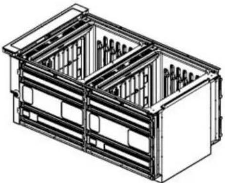
■ Oven support surface must be solid, level and flush with bottom of cabinet cutout. ■ Floor must be able to support a single oven weight of 200 lbs (91 kg) for 30" (76.2 cm) models. ■ Floor must be able to support a double oven weight of 330 lbs (150 kg) for 30" (76.2 cm) models.
IMPORTANT: To avoid damage to your cabinets, check with your builder or cabinet supplier to make sure that the materials used will not discolor, delaminate or sustain other damage.
This oven has been designed in accordance with the requirements of UL and CSA International and complies with the maximum allowable wood cabinet temperatures of 194°F (90°C).
27" (68.6 cm) models
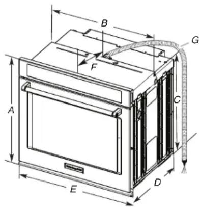
A. 29" (73.6 cm) maximum cabinet overall height B. 25 7/16" (64.6 cm) maximum recessed width C. 26" (65.9 cm) recessed height D. 23 1/4" (59.1 cm) maximum recessed depth E. 26" (65.9 cm) overall width F. 12" (30.5 cm) from back of control panel to start of strain relief G. 48" (121.9 cm) flexible conduit length
30" (76.2 cm) models
A. 29" (73.6 cm) maximum overall height B. 28 7/16" (72.2 cm) maximum recessed width C. 26" (65.9 cm) recessed height D. 23 1/4" (59.1 cm) maximum recessed depth E. 29 3/4" (75.6 cm) overall width F. 12" (30.5 cm) from back of rain control panel to start of strain relief G. 48" (121.9 cm) flexible conduit length
Single Ovens Installed in Cabinet
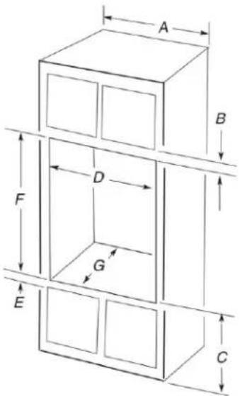
27" (68.6 cm) models
A. 27" (68.6 cm) minimum cabinet width
B. 1" (2.5 cm) top of cutout to bottom of upper cabinet door
C. 32" (81.3 cm) bottom of cutout to floor
D. 25 1/2" (64.8 cm) minimum cutout width
E. 1 1/2" (3.8 cm) minimum bottom of cutout to top of cabinet door
F. 28" (71.2 cm)* recommended cutout height
G. 24" (60.7 cm) cutout depth
30" (76.2 cm) models
A. 30" (76.2 cm) minimum cabinet width
B. 1" (2.5 cm) top of cutout to bottom of upper cabinet door
C. 32" (81.3 cm) bottom of cutout to floor
D. 28 1/2" (72.4 cm) minimum cutout width
E. 1½" (3.8 cm) minimum bottom of cutout to top of cabinet door
F. 28" (71.2 cm)* recommended cutout height
G. 24" (60.7 cm) cutout depth
*NOTE: The cutout height can be between 27 1/4" and 29 7/16" (69.2 cm and 74.8 cm) for single ovens.
*NOTE: Tall shield for installations greater than 28 11/16" (72.9 cm).
Product Dimensions - Double Ovens
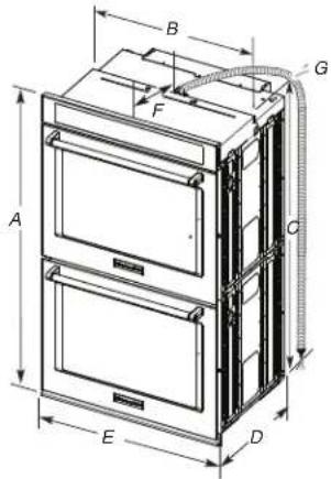
27" (68.6 cm) models
A. 51 3/4" (131.5 cm) maximum overall height
B. 25 7/16" (64.6 cm) maximum recessed width
C. 48 13/16" (124.0 cm) recessed height
D. 23 1/4" (59.1 cm) maximum recessed depth
E. 26 3/4" (68.1 cm) overall width
F. 12" (30.5 cm) from back of control panel to start of strain relief
G. 66" (167.6 cm) flexible conduit length
30" (76.2 cm) models
A. 51 3/4" (131.5 cm) maximum overall height
B. 28 7/16" (72.2 cm) maximum recessed width
C. 48 13/16" (124.0 cm) recessed height
D. 23 1/4" (59.1 cm) maximum recessed depth
E. 29 3/4" (75.6 cm) overall width
F. 12" (30.5 cm) from back of rain control panel to start of strain relief
G. 66" (167.6 cm) flexible conduit length
Cabinet Dimensions - Double Ovens, Standard Installation
Double Ovens Installed in Cabinet
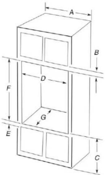
27" (68.6 cm) models
A. 27" (68.6 cm) minimum cabinet width B. 1" (2.5 cm) top of cutout to bottom of upper cabinet door C. 14 3/4" (37.5 cm) bottom of cutout to floor is recommended. 7.5"-14 3/4" (19.1 cm - 37.5 cm) bottom of cutout to floor is acceptable. D. 25 1/2" (64.8 cm) minimum cutout width E. 1 1/2" (3.8 cm) minimum bottom of cutout to top of cabinet door F. 50 1/4" (127.6 cm)* recommended cutout height G. 24" (60.7 cm) cutout depth
30" (76.2 cm) models
A. 30" (76.2 cm) minimum cabinet width B. 1" (2.5 cm) top of cutout to bottom of upper cabinet door C. 14 3/4" (37.5 cm) bottom of cutout to floor is recommended. 7.5"-14 3/4" (19.1 cm - 37.5 cm) bottom of cutout to floor is acceptable. D. 28 1/2" (72.4 cm) minimum cutout width E. 1 1/2" (3.8 cm) minimum bottom of cutout to top of cabinet door F. 50 1/4" (127.6 cm)* recommended cutout height G. 24" (60.7 cm) cutout depth
*NOTE: The cutout height can be between 50" and 52 3/16" (127 cm and 132.6 cm) for double ovens.
NOTE: Contact service to get tall shield for cutouts greater than 50 3/8" (128 cm) to enhance installation
Cabinet Dimensions - Single Ovens, Flush Installations
NOTE: This is an alternate option to install your product in the cabinet and obtain a flush look. For standard installation, refer to section "Cabinet Dimensions - Single Ovens, Standard Installation".
A 25" (63.5 cm) minimum cutout depth is required.
Top and bottom gaps will be 1/8" (0.3 cm) gap above and below the product. Top and bottom gaps are not required for installation. Exposed areas of the cabinet should be finished to match.
Single Ovens Installed in Cabinet
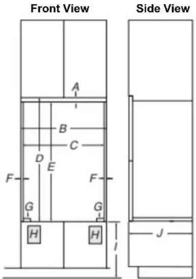
27" (68.6 cm) Models
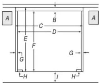
A. 3/4" (1.9 cm) top cleat* B. 27 1/4" (69.2 cm) minimum width of flush inset cutout C. 25 7/8" (65.7 cm) minimum width of opening D. 29 1/4" (74.3 cm) minimum height of flush inset cutout E. 28 1/2" (72.4 cm) recommended cutout height F. 11/16" (1.7 cm) side cleat* G. 1/4" (0.6 cm) recommended with foot. 15/16" to 1 1/8" (2.2 cm to 2.9 cm) allowable without foot. H. Recommended junction box location I. 4 5/8" - 32" (11.7 - 81.3 cm) bottom of cutout to floor J. 25" (63.5 cm) minimum depth of cutout
30" (76.2 cm) Models
A. 3/4" (1.9 cm) top cleat* B. 30 1/4" (76.8 cm) minimum width of flush inset cutout C. 28 7/8" (73.3 cm) minimum width of opening D. 29 1/4" (74.3 cm) minimum height of flush inset cutout E. 28 1/2" (72.4 cm) recommended cutout height F. 11/16" (1.7 cm) side cleat* G. 1/4" (0.6 cm) recommended with foot. 15/16" to 1 1/8" (2.2 cm to 2.9 cm) allowable without foot. H. Recommended junction box location I. 4 5/8" - 32" (11.7 - 81.3 cm) bottom of cutout to floor J. 25" (63.5 cm) minimum depth of cutout
* Cleats and spacers must be recessed (0.5 cm) from the front of the cabinet.
Single Ovens Undercounter - without cooktop installed above
Front View
27" (68.6 cm) Models
A. Recommended junction box location B. 3/4" (1.9 cm) top cleat* C. 27 1/4" (69.2 cm) minimum of flush inset cutout D. 25 7/8" (65.7 cm) minimum of opening E. 29 1/4" (74.3 cm) minimum height of flush inset cutout F. 28 1/2" (72.4 cm) recommended cutout height G. 11/16" (1.7 cm) side cleat* H. 1/4" x 2" (6.4 mm x 5.1 cm) spacer the entire depth of the cabinet* I. 4 5/8" (11.7 cm) bottom of cutout to floor
* Cleats and spacers must be recessed (0.5 cm) from the front of the cabinet.
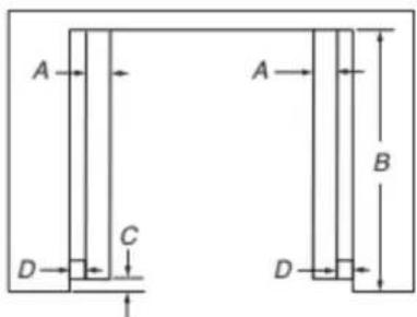
Top View
27" (68.6 cm) Models
A. 2" (5.1 cm) spacer the entire depth of the cutout* B. 25" (63.5 cm) depth of cutout C. 1 3/8" (3.5 cm) recess from front of cabinet D. 11/16" (1.7 cm) side cleat*
* Cleats and spacers must be recessed (3.5 cm) from the front of the cabinet.
Cabinet Dimensions - Double Ovens, Flush Installations
NOTE: This is an alternate option to install your product in the cabinet and obtain a flush look. For standard installation, refer to section "Cabinet Dimensions - Double Ovens, Standard Installation".
A 25 3/8" (64.4 cm) minimum cutout depth is required.
Top and bottom gaps will be 1/8" (0.3 cm) gap above and below the product. Top and bottom gaps not required for installation. Exposed areas of the cabinet should be finished to match.
Double Ovens Installed in Cabinet
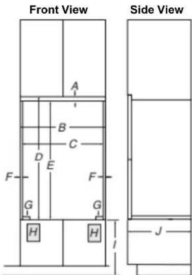
27" (68.5 cm) Models
A. 3/4" (1.9 cm) top cleat* B. 27 1/4" (69.2 cm) minimum width of flush inset cutout C. 25 7/8" (65.7 cm) minimum width of opening D. 52" (132.1 cm) minimum height of flush inset cutout E. 51 1/4" (130.1 cm) recommended cutout height F. 11/16" (1.7 cm) side cleat* G. 1/4" (0.6 cm) recommended with foot. 15/16" to 1 1/16" (2.2 cm to 2.8 cm) allowable without foot. H. Recommended junction box location I. 4 5/8" - 14 3/4" (11.7 - 37.5 cm) bottom of cutout to floor J. 25" (63.5 cm) minimum depth of cutout
30" (76.2 cm) Models
A. 3/4" (1.9 cm) top cleat* B. 30 1/4" (76.8 cm) minimum width of flush inset cutout C. 28 7/8" (73.3 cm) minimum width of opening D. 52" (132.1 cm) minimum height of flush inset cutout E. 51 1/4" (130.1 cm) recommended cutout height F. 11/16" (1.7 cm) side cleat* G. 1/4" (0.6 cm) recommended with foot. 15/16" to 1 1/16" (2.2 cm to 2.8 cm) allowable without foot. H. Recommended junction box location I. 4 5/8" - 32" (11.7 - 81.3 cm) bottom of cutout to floor J. 25" (63.5 cm) minimum depth of cutout
* Cleats and spacers must be recessed (3.5 cm) from the front of the cabinet.
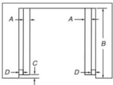
Top View
27" (68.6 cm) Models 30" (76.2 cm) Models
A. 2" (5.1 cm) spacer the entire depth of the cutout* 2" (5.1 cm) spacer the entire depth of the cutout* B. 25 3/8" (64.4 cm) depth of cutout 25 3/8" (64.4 cm) depth of cutout C. 1 3/8" (3.5 cm) recess from front 1 3/8" (3.5 cm) recess from front of cabinet of cabinet D. 11/16" (1.7 cm) side cleat* D. 11/16" (1.7 cm) side cleat*
* Cleats and spacers must be recessed (B.5 cm) from the front of the cabinet.
Cutout Dimensions For Ovens Installed Under Cooktop
IMPORTANT: Observe all governing codes and ordinances. Cooktop must be approved for use over an oven. See cooktop Installation Instructions for cutout dimensions. Center the cooktop cutout over oven cutout.
Ovens approved for this type of installation have an approval label located on the top of the oven.
To avoid damage to your cabinets, check with your builder or cabinet supplier to make sure that the materials used will not discolor, delaminate or sustain other damage. This oven has been designed in accordance with UL and CSA International and complies with the maximum allowable wood cabinet temperatures of 194°F (90°C).
Approved Built-In Oven and Electric Coil/Radiant/Induction Cooktop Combinations or without Cooktop Installed above Oven
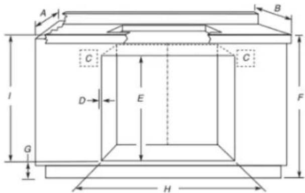
A. 24" (61 cm) cabinet depth B. 25" (63.5 cm) countertop depth C. Recommended oven and cooktop junction box locations D. Allow 5/8" (1.6 cm) for oven trim to overlap on each side. E. 27 3/4" (70.5 cm) minimum cutout height F. 36" (91.4 cm) from cabinet base to countertop G. 45/8" (11.7 cm) maximum from cabinet base with feet installed. If dimension "F" is greater than 36" (91.4 cm), dimension "G" can be increased the same difference for induction combinations
H. See Cutout Dimensions chart
I. 31 3/8" (82.2 cm) from top of countertop to bottom of cutout
CUTOUT DIMENSIONS (H)
| or t Oven Size been | Minimum Oven Cutout Dimension |
| 24" (61 cm) 22 | 1/2 " (57.2 cm) |
| res | |
| 27" (68.6 cm) 25 | 1/2 " (64.8 cm) |
| 30" (76.2 cm) 28 | 1/2 " (72.4 cm) |
For the approved model number combinations, refer to the undercounter label located on top of the oven chassis and on the bottom of the cooktop burner box.
NOTE: For undercounter installation, it is recommended that the junction boxes for oven and cooktop be located in the adjacent right or left cabinet. A 1" (2.5 cm) minimum diameter hole should have been drilled in the upper rear right or left corner of the six wall surface to pass the appliance cable through to the junction box.
Approved Built-In Oven and Gas Cooktop Combinations
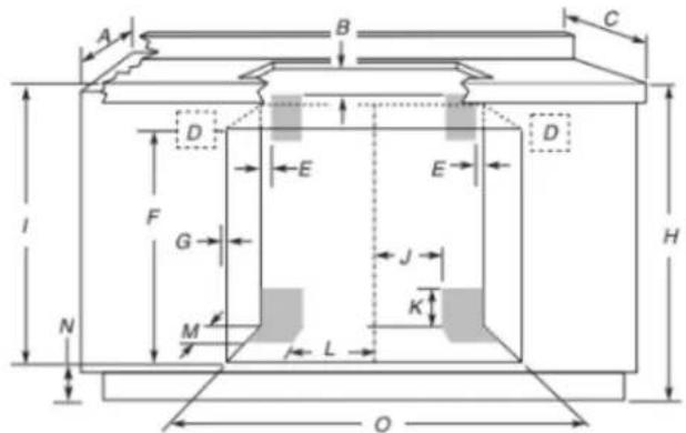
A. 24" (61 cm) cabinet depth B. 1" (2.5 cm) clearance to countertop C. 25" (63.5 cm) countertop depth D. Recommended oven junction box locations E. 1" (2.5 cm) clearance to cabinet F. 27 3/4" (70.5 cm) minimum cutout height G. Allow 5/8" (1.6 cm) for trim to overlap on each side. H. 36" (91.4 cm) from cabinet base to countertop I. 31 3/8" (79.7 cm) from top of countertop to bottom of cutout Gas line through wall: 10" (26.7 cm) to center of cutout, 3 1/4" (8.3 cm) Gas line through floor: 10" (26.7 cm) to center of cutout, 3 1/2" (8.9 cm) 4 5/8" (11.7 cm) maximum from cabinet base with feet installed See Cutout Dimensions chart
CUTOUT DIMENSIONS (O)
| Oven Size | Minimum Oven Cutout Dimension |
| 24" (61 cm) 22 | 1/2 " (57.2 cm) |
| 27" (68.6 cm) 25 | 1/2 " (64.8 cm) |
| 30" (76.2 cm) 28 | 1/2 " (72.4 cm) |
| 36" (91.4 cm) 34 | 1/2 " (87.6 cm) |
For the approved model number combinations, refer to the undercounter label located on top of the oven chassis.
NOTE: For undercounter installation, it is recommended that the junction box for the oven be located in the adjacent right or left cabinet. A 1" (2.5 cm) minimum diameter hole should have been drilled in the upper rear right or left corner of the side wall to pass the appliance cable through to the junction box.
The upper shaded areas are recommended locations for a recessed junction box for a 120 V grounded outlet for the cooktop.
Lower shaded areas are recommended locations for flexible or rigid gas pipe installation. The gas connection on the cooktop is on the right (same location as "J" in the above diagram). The gas pipe can be installed on either side of the cutout, and either through the floor or through the wall. Refer to local codes regarding the use of gas lines.
Electrical Requirements
WARNING

Electrical Shock Hazard
Electrically ground appliance.
Failure to do so could result in death, fire, or electrical shock.
If codes permit and a separate ground wire is used, it is recommended that a qualified electrical installer determine that the ground path and the wire gauge are in accordance with local codes.
Check with a qualified electrical installer if you are not sure the oven is properly grounded.
This oven must be connected to a grounded metal, permanent wiring system.
Be sure that the electrical connection and wire size are adequate and in conformance with the National Electrical Code, ANSI/NFPA 70-latest edition or CSA Standards C22.1-94, Canadian Electrical Code, Part 1 and C22.2 No. O-M91-latest edition, and all local codes and ordinances.
A copy of the above code standards can be obtained from:
National Fire Protection Association
1 Batterymarch Park
Quincy, MA 02169-7471
CSA International
8501 East Pleasant Valley Road
Cleveland, OH 44131-5575
Electrical Connection
To properly install your oven, you must determine the type of electrical connection you will be using and follow the instructions provided for it here.
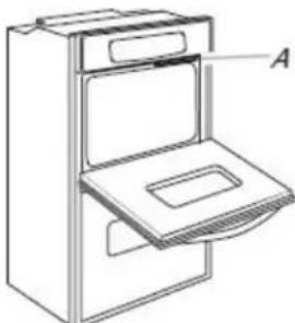
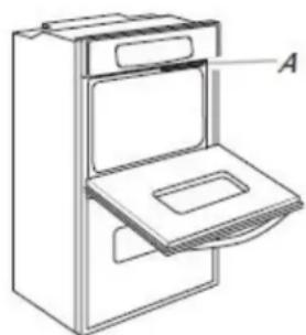
■ Oven must be connected to the proper electrical voltage and frequency as specified on the model/serial/rating plate. The model/serial/rating plate is located under the control panel on single ovens and under the control panel on the upper oven cavity on double ovens. See the following illustrations.
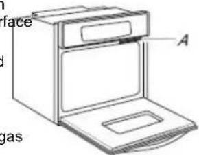
Single oven
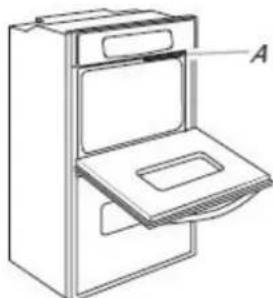
Double oven
A. Model/serial/rating plate
A. Model/serial/rating plate
■ Models rated from 7.3 to 9.6 kW at 240 V (5.4 to 7.4 kW at 208 V) require a separate 40 A circuit. Models rated at 4.8 k and below at 240 V (3.6 kW and below at 208 V) require a separate 20 A circuit.
■ A circuit breaker is recommended. ■ Connect directly to the fused disconnect (or circuit breaker box) through flexible, armored, or nonmetallic sheathed, copper cable (with grounding wire). See "Make Electrical Connection" section. ■ Flexible conduit from the oven should be connected directly to the junction box. ■ Fuse both sides of the line. ■ Do not cut the conduit. The length of conduit provided is for serviceability of the oven. ■ A UL listed or CSA-approved conduit connector must be provided. If the house has aluminum wiring, follow the procedure below: Connect the aluminum wiring using special connectors and/or tools designed and UL listed for joining copper to aluminum. Follow the electrical connector manufacturer's recommended procedure. Aluminum/copper connection must conform with local codes and industry-accepted wiring practices.
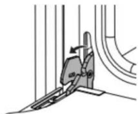
- Locate the oven door hinge locks in both corners of the oven door, and rotate the hinge locks toward the oven door to the unlocked position. If the door hinge lock is not rotated fully (see unlocked position in illustration), the door will not remove properly.
Oven door hinge lock in locked position; oven door hinge lock in unlocked position
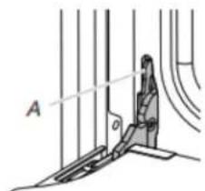
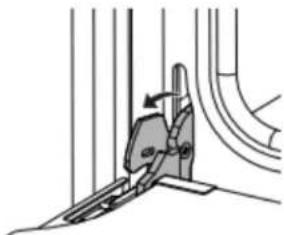
A. Grip here to rotate
INSTALLATIONS
Prepare Built-In Oven
- Decide on the final location for the oven. Avoid drilling or cutting into house wiring during installation.
WARNING
Excessive Weight Hazard
Use two or more people to move and install or uninstall appliance.
Failure to do so can result in back or other injury.
- To avoid floor damage, set the oven onto cardboard prior to installation. Do not use handle or any portion of the front frame for lifting.
- Remove the shipping materials and tape from the oven. Remember to keep the corner posts and other materials that may be needed for installation.
- Remove the hardware package from inside the bag containing literature.
- Remove and set aside racks, attachments, and other parts from inside the oven.
- Move oven and cardboard close to the oven's final location.
Remove Oven Door(s)
IMPORTANT: Use 2 hands to remove oven door. For double ovens, repeat the process for each door.
- Gently start to close the door. The door will stop at a partial closed position.
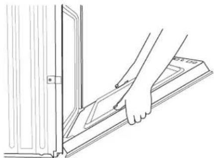
- Using 2 hands, grasp the edges of the oven door. Close the oven door slightly past the stop position to take the weight of the door hinges, and then pull the oven door up.
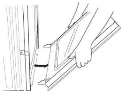
- Prior to removing the oven door, prepare a surface where you will place it. This surface should be flat and covered with a soft blanket, or use the corner posts from your packaging material. Set the oven door aside on the prepared covered work surface.
- Fully open the oven door.
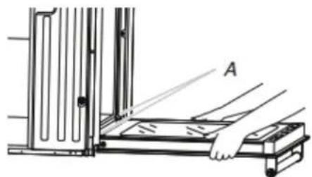
- To continue with the oven installation, go to the "Positioning Oven Feet for Multiple Cabinet Cutout Heights" section.
A. Door hinges
Positioning Oven Feet for Multiple Cabinet Cutout Heights
- Remove the foot from the right front spacer by removing the #8-18 x 3/8" screw.
NOTE: Do not remove the spacer.
Single Ovens
The positioning of the oven feet allow a single oven to be installed in a cutout height between 5/16" and 29/16" (68.4 cm and 74.8 cm). Refer to the following instructions to position the feet for the size of your cabinet cutout.
The oven feet need to be installed to allow the oven to be installed in a Flush Installation or in Standard Installations where the cutout height is 1/42" (107.9 cm) or more.
The oven feet do not need to be changed. They are positioned correctly as received.
Go to the "Make Electrical Connection" section.
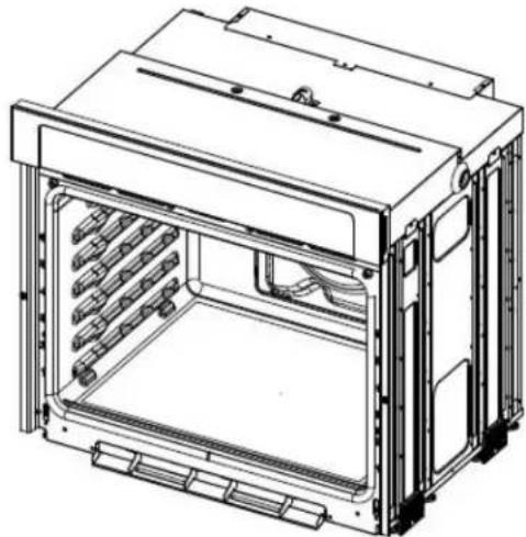
Cutout Height is Between 27 1/4" and 27 11/16" (69.2 cm and 70.3 cm)
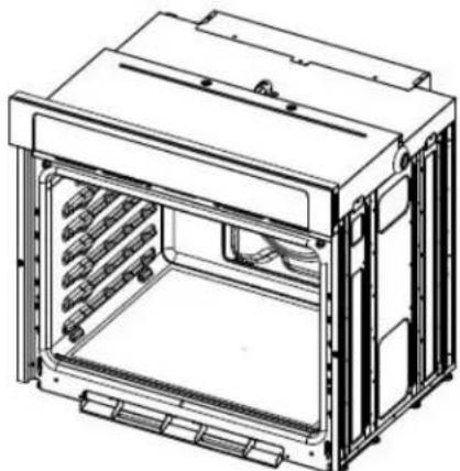
- Using 2 or more people, place the oven on its back on a covered surface.
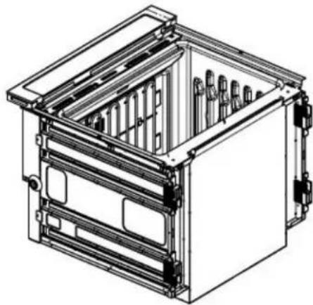
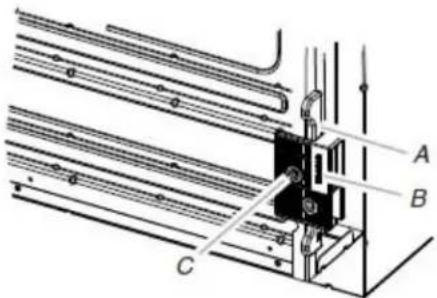
A. Spacer
B. Foot
C. #8-18 x 3/8" (9.5 mm) screw
- In the same manner, remove the feet on the right rear, left front, and left rear of the oven.
- Using 2 or more people, place the oven in its upright position.
- Go to the "Make Electrical Connection" section.
Cutout Height is between 28 1/8" and 29 1/16" (72.8 cm and 74.8 cm)
- Using 2 or more people, place the oven in its upright position.
NOTE: For installation, the tall shield is required to replace the shield that came with the unit. Please refer to your Quick Start Guide for the service number to call and request at no charge.
- Using 2 or more people, place the oven on its back on a covered surface.
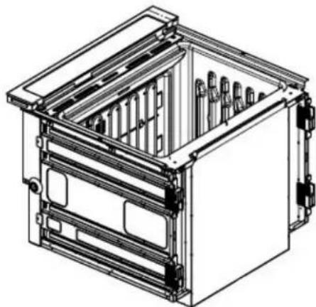
- Remove the foot from the right front spacer by removing the #8-18 x 3/8" (9.5 mm) screw.
NOTE: Do not remove the spacer.
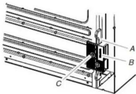
A. Spacer B. Foot C. #8-18 x 3/8" (9.5 mm) screw
- Rotate the foot 90° so the short side of the foot is positioned toward the top of the oven.
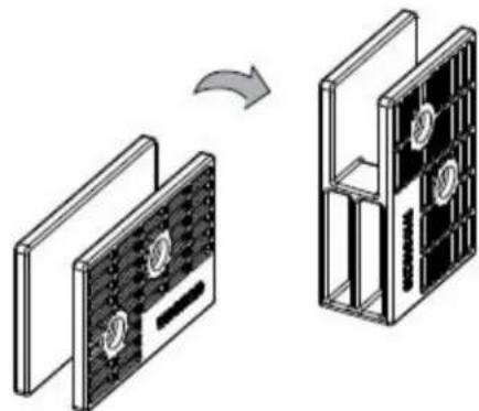
- Reinstall the foot to the spacer using the #8-18 x 3/8" (9.5 mm) screw previously removed.
- In the same manner, remove, rotate, and reinstall the feet on the right rear, left front, and left rear of the oven.
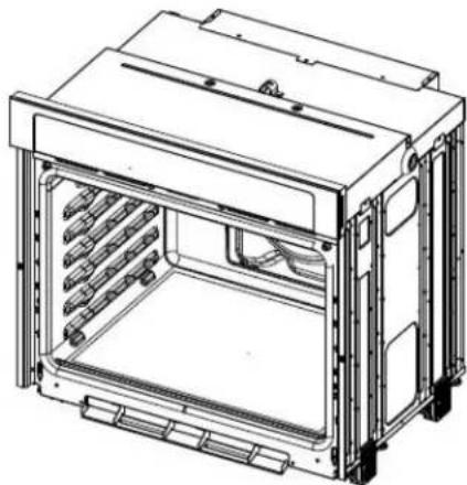
- Go to the "Make Electrical Connection" section.
Double Ovens
The positioning of the oven feet allows a double oven to be installed in a cutout height between 4 and 52" (124.1 cm and 132.6 cm). Refer to the following instructions to position the feet for the size of your cabinet cutout.
Cutout Height is Between 748" and 50/16" (124.1 cm and 128.1 cm)
The oven feet do not need to be installed. The oven is configured correctly as received.
NOTE: Do not remove the spacers.
Go to the "Make Electrical Connection" section.
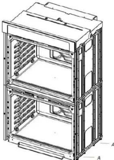
A. Spacers
Cutout Height is Between 150" and 5118" (128.2 cm and 129.9 cm) or for Flush Installation
- Using 2 or more people, place the oven on its back on a covered surface.
- Install a front foot on the left front spacer using a #8-18 x 3. (9.5 mm) screw.
NOTE: Position the foot so the long side of the foot is facing toward the inside of the oven.
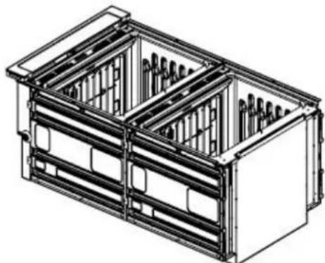
- Install a rear foot on the left rear spacer using a #8-18 x 3/8" (9.5 mm) screw.
NOTE: Position the foot so the long side of the foot is facing toward the top of the oven.
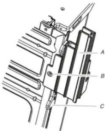
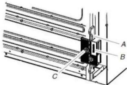
A. Spacer B. Rear foot C. #8-18 x 3/8" (9.5 mm) screw
- In the same manner, install a rear foot on the right rear of the oven.
A. Front Foot B. #8-18 x 3/8" (9.5 mm) screw C. Spacer
- In the same manner, install a front foot on the right front of oven.
- Using 2 or more people, place the oven in its upright position
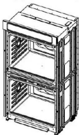
- Go to the "Make Electrical Connection" section.
Cutout Height is Between 51 6/16" and 52 16/16" (130.0 cm and 132.6 cm)
- Install a front foot on the left front using a #8-18 x 3/8" (9.5 mm) screw.
NOTE: For installation, the tall shield is also required to replace the shield that came with the unit. Please refer to your Quick Guide for the service number to call and request at no charge.
NOTE: Position the foot so the short side of the foot is facing toward the top of the oven.
- Using 2 or more people, place the oven on its back on a covered surface.
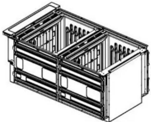
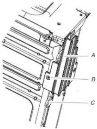
- Install a rear foot on the left rear spacer using a #8-18 x 3/8" (9.5 mm) screw.
NOTE: Position the foot so the short side of the foot is facing toward the top of the oven.
A. Front Foot B. #8-18 x 3/8" (9.5 mm) screw C. Spacer
- In the same manner, install a front foot on the right front of oven.
- Using 2 or more people, place the oven in its upright position
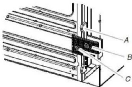
A. Spacer B. Rear foot C. #8-18 x 3/8" (9.5 mm) screw
- In the same manner, install a foot on the right rear of the oven.
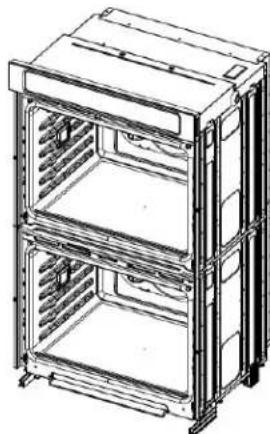
- Go to the "Make Electrical Connection" section.
Make Electrical Connection
For Single Ovens
WARNING Electrical Shock Hazard
Disconnect power before servicing.
Use 12 gauge copper wire.
Electrically ground oven.
Failure to follow these instructions can result in death, fire, or electrical shock.
For Double Ovens
WARNING Electrical Shock Hazard
Disconnect power before servicing.
Use 8 gauge copper wire.
Electrically ground oven.
Failure to follow these instructions can result in death, fire, or electrical shock.
This oven is manufactured with a neutral (white) power supply wire and a cabinet-connected green (or bare) ground wire.
- Disconnect power.
- Feed the flexible conduit from the oven through the open the cabinet.
- Remove junction box cover, if it is present.
- Install a UL listed or CSA approved conduit connector to junction box.
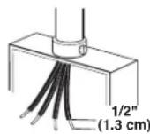
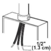
Electrical Connection Options Chart
If your home has: Go to section:
4-wire
4-Wire Cable from Home
Power Supply
3-wire
3-Wire Cable from Home
Power Supply
4-Wire Cable from Home Power Supply
IMPORTANT: Use the 4-wire cable from home power supply in the U.S. where local codes do not allow grounding through neutral, New Branch circuit installations (1996 NEC), mobile homes and recreational vehicles, new construction and in Canada.
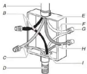
A. Cable from home power supply White wires B. Black wires G. UL listed wire connectors C. Red wires H. Green (or bare) ground wires D. 4-wire flexible conduit from I. UL listed or CSA approved oven conduit connector E. Junction box
1 Connect the 2 black wires (B) together using a UL listed wire connector.
- Connect the 2 red wires (C) together using a UL listed wire connector.
- Untwist white wire from green (or bare) ground wire coming from the oven.
- Connect the 2 white wires (F) together using a UL listed wire connector.
- Connect the green (or bare) ground wire (H) from the oven cable to the green (or bare) ground wire (in the junction box) using a UL listed wire connector.
- Install junction box cover.
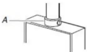
A. UL listed or CSA approved conduit connector
- Route the flexible conduit from the oven to the junction box through a UL listed or CSA approved conduit connector.
- Tighten screws on conduit connector.
- See "Electrical Connection Options Chart" to complete installation for your type of electrical connection.
3-Wire Cable from Home Power Supply - U.S. Only
IMPORTANT: Use the 3-wire cable from home power supply where local codes permit a 3-wire connection.
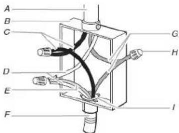
A. Cable from home power supply B. Junction box C. Black wires D. White wires E. Green (or bare) ground wire (from oven) F. 4-wire flexible conduit from oven G. Red wires H. UL listed wire connectors I. UL listed or CSA approved conduit connector
- Connect the 2 black wires (C) together using a UL listed wire connector.
- Connect the 2 white wires (D) and the green (or bare) ground wire (of the oven cable) using a UL listed wire connector.
- Connect the 2 red wires (G) together using a UL listed wire connector.
- Install junction box cover.
- The bottom vent trim and bottom vent shield are shipped in the foam packing at the top of the oven. Tall bottom vent shield are used when the oven is installed with the feet in the tall position. Please contact service for or to be shipped to you free of charge.
Install Oven
- Using 2 or more people, lift the oven partially into the cabinet cutout. Use the oven opening as an area to grip.
NOTE: Push against seal area of the oven front frame when pushing the oven into the cabinet. Do not push against the outside edges.
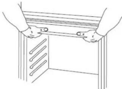
- Push against the seal area of the front frame to push the oven into the cabinet until the back surface of the front frame touches the front wall of the cabinet.

- Push oven completely into the cabinet and center the oven into the cabinet cutout.
- Securely fasten the oven to the cabinet using the #8-14 x 3/4" (1.9 cm) screws provided.
Insert the screws through hole in black trim aligning with hole in oven frame. Do not overtighten screws.
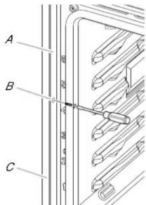
A. Oven frame B. Side trim hole
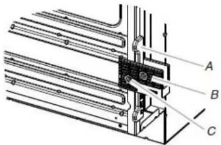
■ Align vent tab (B) with oven frame (A) as shown. ■ Using one #8-18 x 3/8" (9.5 mm) screw (C) on each side the shield tab (B), fasten the vent shield securely to the oven frame (A).
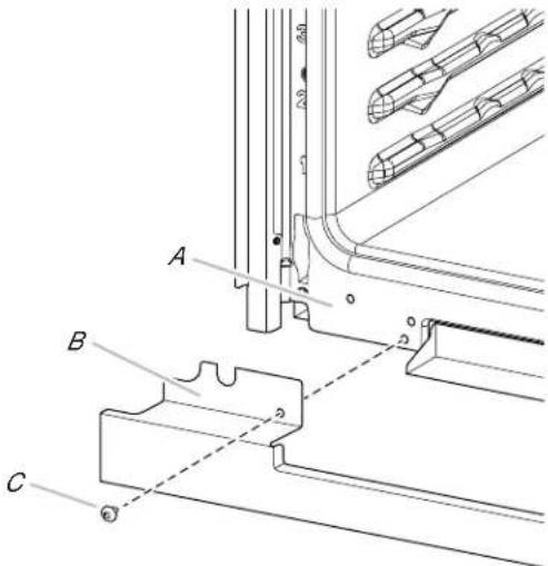
A. Oven frame B. Shield tab C. #8-18 x 3/8" (9.5 mm) screws
- After the bottom vent shield is installed.
- If F9E0 error code is encountered upon powering up the unit
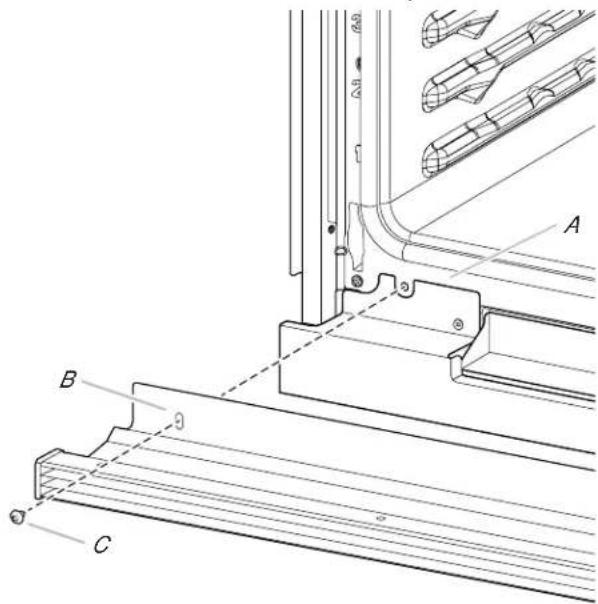
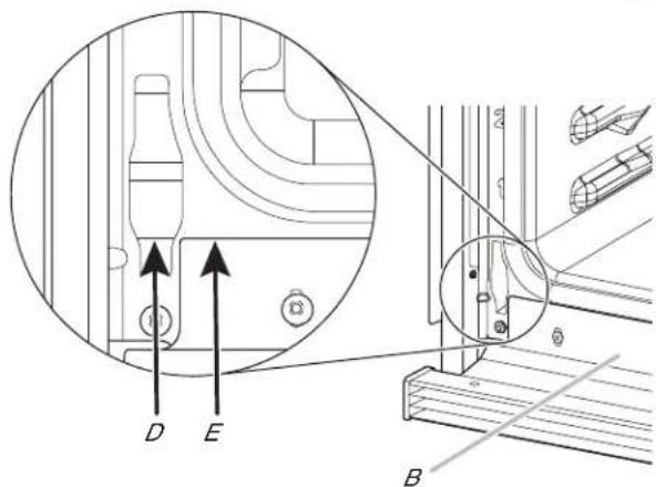
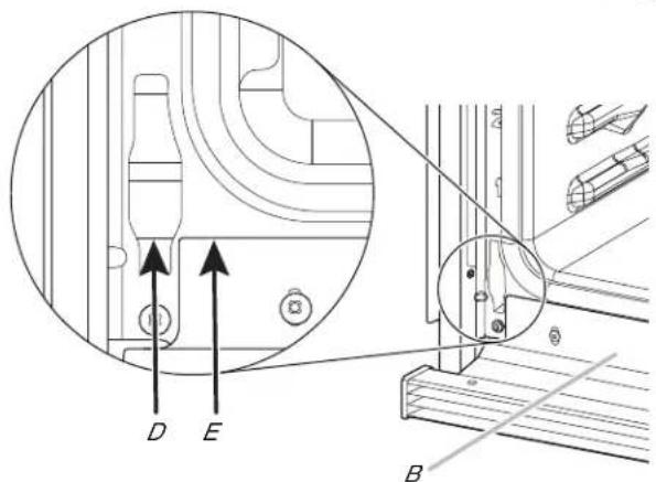
■ Align the bottom vent trim tab (B) with the oven frame as shown.
the appliance is wired incorrectly at the Junction Box or
Electrical Panel. Contact a qualified electrician to verify the
home electrical supply and the hardwire connection at the
Junction Box or Electrical Panel (See the Electrical
Connection Options section).
■ Using one #8-18 x 3/8" (9.5 mm) screw (C) on each side,
align the top edge of the bottom vent trim
tab (E) with the hinge receiver edge (D) as shown.
■ Fasten the bottom vent trim securely to the oven frame.
(1) Install Deflector Kit (on some models)
On single and double oven models installed above a warming drawer or for ovens installed using flush installation cabinetry, a deflector kit must be installed. See the "Tools and Parts" section for information on ordering.
Parts Supplied in Deflector Kit
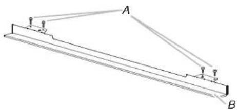
A. Phillips head screws (4), only 2 screws for 27" (68.6 cm) size
B. Deflector (1)
Install Deflector Kit
- Install the deflector (B) to the lower vent piece (D) using two #8-18 x 1/4" (6.4 mm) screws on each side.
NOTE: On 27" (68.6 cm) models, only one #8-18 x 1/4"
(6.4 mm) screw is used on each side.
A. Oven frame
C. #8-18 x 3/8" (9.5 mm)
B. Trim tab
screw
D. Hinge receiver edge
E. Bottom Vent Trim Tab top edge
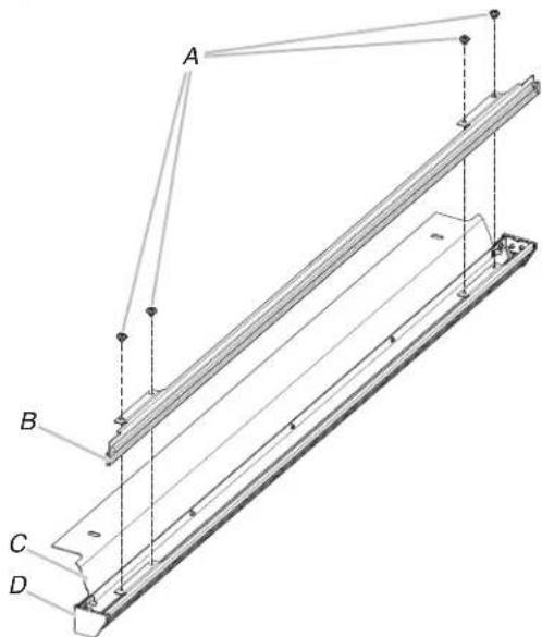
A. #8-18 x 1/4" (6.4 mm) screws
C. Upper vent piece
D. Lower vent piece
B. Deflector
- Replace the oven racks.
- Replace the oven door. See the "Replace Oven Door(s)" section.
- Check that the door is free to open and close. If it is not, repeat the removal and installation procedures. See the "Prepare Built-In Oven" section.
- Repeat for lower oven door.
IMPORTANT: For proper oven operation, check that the gap between bottom of the door and bottom vent trim is at least 1/4" (6.4 mm).
- Reconnect power.
- The display panel will light and boot up.
- If the display panel does not light, reference the Warranty.
- Align vent tab (B) with oven frame (A) as shown in the following illustration.
- Using one #8-18 x 3/8" (9.5 mm) screw (E) on each side of the oven cavity slot, make sure the door hinge notch is engaged on the bottom vent tab (B), fasten the vent securely to the oven.
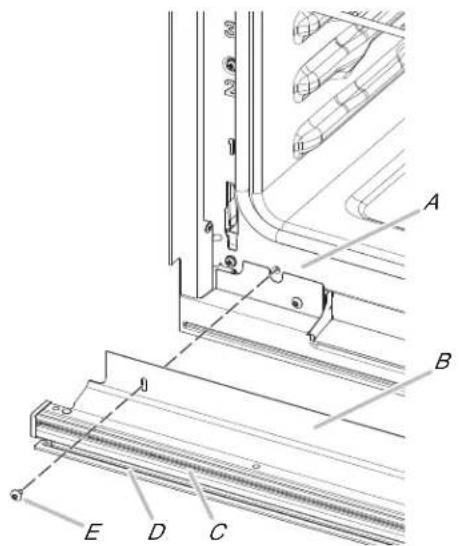
A. Oven frame
D. Deflector
B. Vent tab
E. #8-18 x 3/8" (9.5 mm) screw
C. Oven vent
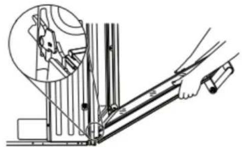
IMPORTANT: Do not close the door at this step or damage may occur to the door hinge.
- Lower the oven door to the fully open position. If the oven door does not open to a full 90°, repeat steps 1 through 3.
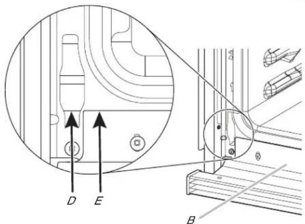
- Locate the oven door hinge locks in the corners of the oven door, and rotate the hinge locks toward the oven cavity to the locked position.
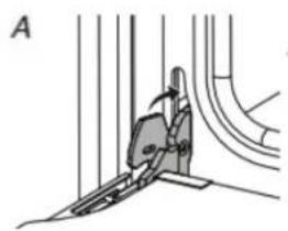
A. Unlocked position
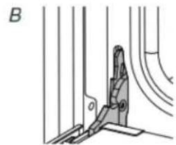
B. Locked position
Replace Oven Door(s)
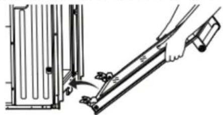
- Using two hands, grasp side edges of door at the midpoint. Face the oven cavity.
- Locate the slots on each side of the oven cavity for the door hinge locks.
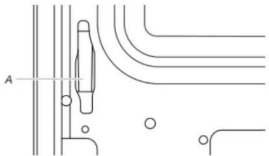
A. Slot in the oven cavity for door hinge lock
- After the door hinges have been locked, gently swing the door upward to close. The door should not be forced closed.
- When the hinges are properly installed and the door is closed there should be an even gap between the door and the control panel. If one side of the oven door is lower than the other, the hinge on that side is not properly installed.
- Using 2 hands, grasp the edges of the oven door. At a 45° angle, insert the hinges at the same time, and push the oven door into the oven cavity slot to replace. You may need to gently shift the door from side to side as you push.
Complete Installation
- Check that all parts are now installed. If there is an extra part, go back through the steps to see which step was skipped.
- Check that you have all of your tools.
- Dispose of/recycle all packaging materials.
- For oven cleaning, read the "Oven Maintenance and Care" section.
Check Operation of Single and Double Ovens
- Turn on power.
- At first use, set up the languages, clock, and any other preferences, if available. For more information, read the online "Control Guide".
- Start a broil cycle.
NOTE: Odors and smoke are normal when the oven is used the first few times.
- Wait 5 minutes, then check for heat.
If Oven(s) Does Not Operate, Check the Following:
■ Household fuse is intact and tight; or circuit breaker has not tripped. ■ Electrical supply is connected. ■ See the online "Troubleshooting".
- Place the SatinGlide Roll-Out Extension Rack for Smart Oven+ Attachments in the lowest rack position in the unit to make sure the correct accessory rack is on the bottom.
- Press UPPER CANCEL/LOWER CANCEL on double ovens, or press CANCEL on single ovens.
If you need Assistance or Service:
Please refer to the Quick Start Guide for contact information.
BUILT-IN OVEN SAFETY
Front view
National Fire Protection Association
1 Batterymarch Park
Quincy, MA 02169-7471
CSA International
8501 East Pleasant Valley Road
Cleveland, OH 44131-5575
Single ovens
Double ovens
A. Shim
B. Foot
C. Screw No. 8-18 x 3/8" (9.5 mm)
A. Spacer shims
A. Shim
B. Rear foot
C. Screw No. 8-18 x 3/8" (9.5 mm)
A. Front foot B. Screw No. 8-18 x 3/8" (9.5 mm) C. Shim
A. Shim B. Rear foot C. Screw No. 8-18 x 3/8" (9.5 mm)
A. Front foot B. Screw No. 8-18 x 3/8" (9.5 mm) C. Shim
B. Locked position
27" (68.6 cm) models 30" (76.2 cm) models
27" (68.6 cm) models 30" (76.2 cm) models
A. 27" (68.6 cm) minimum cabinet width
27" (68.6 cm) models 30" (76.2 cm) models
27" (68.6 cm) models 30" (76.2 cm) models
F. 11/16" (1.7 cm) side shim*
F. 11/16" (1.7 cm) side shim*
Front view
27" (68.6 cm) models
G. 11/16" (1.7 cm) side shim*G.
D. 11/16" (1.7 cm) side shim*D.
30" (76.2 cm) models
11/16" (1.7 cm) side shim*
F. 11/16" (1.7 cm) side taco*
F. 11/16" (1.7 cm) side taco*
D. 11/16" (1.7 cm) side taco*
Models of 30" (76.2 cm)
D. 11/16" (1.7 cm) side taco*
National Fire Protection Association
1 Batterymarch Park
Quincy, MA 02169-7471
CSA International
8501 East Pleasant Valley Road
Cleveland, OH 44131-5575
Electrical connection
Single ovens
Double oven
A. Model/serial/rating plate. Model/serial/rating plate nominal values
A. Separators
A. Spacer B. Rear leg C. Screw No. 8-18 x 3/8" (9.5 mm)
A. Front leg B. Screw No. 8-18 x 3/8" (9.5 mm) C. Spacer
A. Spacer B. Rear leg C. Screw No. 8-18 x 3/8" (9.5 mm)
A. Oven frame B. Guard tab C. Screw No. 8-18 x 3/8" (9.5 mm)
A. Oven frame D. Deflector
B. Locked position
- BUILT-IN ELECTRIC SINGLE AND DOUBLE OVEN OWNER'S MANUAL
- OWNER'S MANUAL FOR BUILT-IN ELECTRIC SINGLE OR DOUBLE OVEN
- TABLE OF CONTENTS
- BUILT-IN OVEN SAFETY
- YOUR SAFETY AND THE SAFETY OF OTHERS ARE VERY IMPORTANT
- DANGER
- WARNING
- IMPORTANT SAFETY INSTRUCTIONS
- SAVE THESE INSTRUCTIONS
- FOR SELF-CLEANING OVENS
- INTERNET CONNECTIVITY GUIDE FOR CONNECTED APPLIANCES ONLY
- YOU WILL NEED
- FEDERAL COMMUNICATIONS COMMISSION (FCC) COMPLIANCE NOTICE
- INDUSTRY CANADA (IC) COMPLIANCE NOTICE
- EXTERIOR PORCELAIN ENAMEL SURFACES (ON SOME MODELS)
- CLEANING METHOD
- STAINLESS STEEL (ON SOME MODELS)
- STAINLESS STEEL AND BLACK STAINLESS STEEL (ON SOME MODELS)
- METALLIC PAINT (ON SOME MODELS)
- CONTROL PANEL AND OVEN DOOR EXTERIOR
- OVEN RACKS
- UNLESS CLEANING METHOD
- AIR FRY BASKET (ON SOME MODELS)
- OVEN CAVITY OVEN DOOR INTERIOR
- POWERED ATTACHMENTS (ON SOME MODELS)
- SELF-CLEANING CYCLE
- PREPARE OVEN
- IMPORTANT
- HOW THE CYCLE WORKS
- TO SELF-CLEAN
- DELAY START: (ON SELECT MODELS)
- VERSION A
- VERSION B
- TO STOP SELF-CLEANING ANYTIME
- STEAM CLEAN (ON SOME MODELS)
- HELPFUL HINTS
- TO STEAM CLEAN
- INSTALLATION INSTRUCTIONS
- TOOLS AND PARTS
- TOOLS NEEDED
- PARTS NEEDED
- PARTS SUPPLIED
- LOCATION REQUIREMENTS
- PRODUCT DIMENSIONS - SINGLE OVENS
- 27" (68.6 CM) MODELS
- 30" (76.2 CM) MODELS
- SINGLE OVENS INSTALLED IN CABINET
- PRODUCT DIMENSIONS - DOUBLE OVENS
- CABINET DIMENSIONS - DOUBLE OVENS, STANDARD INSTALLATION
- CABINET DIMENSIONS - SINGLE OVENS, FLUSH INSTALLATIONS
- SINGLE OVENS UNDERCOUNTER - WITHOUT COOKTOP INSTALLED ABOVE
- CABINET DIMENSIONS - DOUBLE OVENS, FLUSH INSTALLATIONS
- DOUBLE OVENS INSTALLED IN CABINET
- 27" (68.5 CM) MODELS
- 27" (68.6 CM) MODELS 30" (76.2 CM) MODELS
- CUTOUT DIMENSIONS FOR OVENS INSTALLED UNDER COOKTOP
- APPROVED BUILT-IN OVEN AND GAS COOKTOP COMBINATIONS
- FOR THE APPROVED MODEL NUMBER COMBINATIONS, REFER TO THE UNDERCOUNTER LABEL LOCATED ON TOP OF THE OVEN CHASSIS
- ELECTRICAL REQUIREMENTS
- ELECTRICAL CONNECTION
- INSTALLATIONS
- PREPARE BUILT-IN OVEN
- REMOVE OVEN DOOR(S)
- POSITIONING OVEN FEET FOR MULTIPLE CABINET CUTOUT HEIGHTS
- SINGLE OVENS
- DOUBLE OVENS
- CUTOUT HEIGHT IS BETWEEN 150" AND 5118" (128.2 CM AND 129.9 CM) OR FOR FLUSH INSTALLATION
- MAKE ELECTRICAL CONNECTION
- FOR SINGLE OVENS
- FOR DOUBLE OVENS
- ELECTRICAL CONNECTION OPTIONS CHART
- 4-WIRE CABLE FROM HOME POWER SUPPLY
- 3-WIRE CABLE FROM HOME POWER SUPPLY - U.S. ONLY
- INSTALL OVEN
- INSTALL DEFLECTOR KIT (ON SOME MODELS)
- PARTS SUPPLIED IN DEFLECTOR KIT
- INSTALL DEFLECTOR KIT
- REPLACE OVEN DOOR(S)
- COMPLETE INSTALLATION
- CHECK OPERATION OF SINGLE AND DOUBLE OVENS
- MODELS OF 30" (76.2 CM)
Brand : WHIRLPOOL
Model : WOEC5027LW
Category : Electric oven