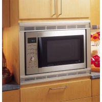
JX1527CWC - Microwave Oven GE - Free user manual and instructions
Find the device manual for free JX1527CWC GE in PDF.


| Product Type | Built-in Microwave Oven |
| Brand | GE |
| Model | JX1527CWC |
| Opening Dimensions (27 in) | Height 18 3/4 in, Width 24 ± 1/16 in, Min Depth 21 1/2 in (external outlet) or 23 in (internal outlet) |
| Opening Dimensions (30 in) | Height 18 3/4 in, Width 24 ± 1/16 in, Min Depth 21 1/2 in or 23 in |
| Power Supply | 120 V, 60 Hz, grounded 3-prong outlet |
| Base Support Weight | Minimum 100 lb (45.3 kg) |
| Capacity | Approx. 1.5 cu ft (estimate) |
| Main Functions | Microwave cooking, defrost, timer, +30s button |
| Cleaning | Clean interior with a damp cloth and mild soap |
| Safety | Anti-tip bracket included, electrical installation in compliance with codes |
| Included Parts | Trim kit, ducts, brackets, screws, template |
| Repairability | Parts available through GE after-sales service |
Frequently Asked Questions - JX1527CWC GE
User questions about JX1527CWC GE
0 question about this device. Answer the ones you know or ask your own.
Ask a new question about this device
Download the instructions for your Microwave Oven in PDF format for free! Find your manual JX1527CWC - GE and take your electronic device back in hand. On this page are published all the documents necessary for the use of your device. JX1527CWC by GE.
USER MANUAL JX1527CWC GE
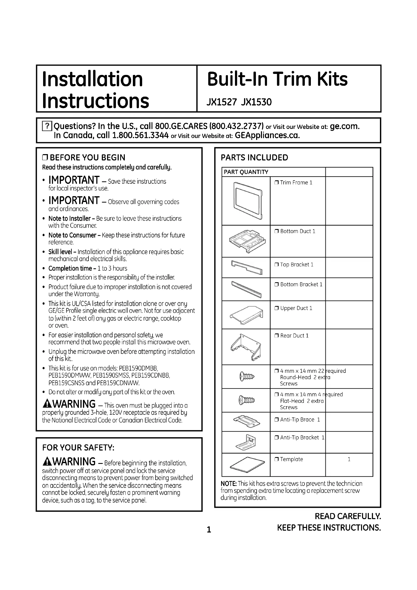
Installation Instructions
Built-In Trim Kits
JX1527 JX1530
Questions? In the U.S., call 800.GE.CARES (800.432.2737) or Visit our Website at: ge.com. In Canada, call 1.800.561.3344 or Visit our Website at: GEAppliances.ca.
BEFORE YOU BEGIN
Read these instructions completely and carefully.
- IMPORTANT – Save these instructions for local inspector's use.
- IMPORTANT – Observe all governing codes and ordinances.
- Note to Installer – Be sure to leave these instructions with the Consumer.
- Note to Consumer – Keep these instructions for future reference.
- Skill level – Installation of this appliance requires basic mechanical and electrical skills.
• Completion time – 1 to 3 hours - Proper installation is the responsibility of the installer.
- Product failure due to improper installation is not covered under the Warranty.
- This kit is UL/CSA listed for installation alone or over any GE/GE Profile single electric wall oven. Not for use adjacent to (within 2 feet of) any gas or electric range, cooktop or oven.
- For easier installation and personal safety, we recommend that two people install this microwave oven.
- Unplug the microwave oven before attempting installation of this kit.
- This kit is for use on models: PEB1590DMBB, PEB1590DMWW, PEB1590SMSS, PEB159CDNBB, PEB159CSNSS and PEB159CDNWW.
- Do not alter or modify any part of this kit or the oven.
⚠ WARNING — This oven must be plugged into a properly grounded 3-hole, 120V receptacle as required by the National Electrical Code or Canadian Electrical Code.
FOR YOUR SAFETY:
⚠ WARNING — Before beginning the installation, switch power off at service panel and lock the service disconnecting means to prevent power from being switched on accidentally. When the service disconnecting means cannot be locked, securely fasten a prominent warning device, such as a tag, to the service panel.
PARTS INCLUDED
| PART QUANTITY | ||
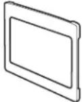 | ☐ Trim Frame 1 | |
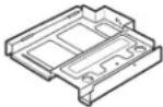 | ☐ Bottom Duct 1 | |
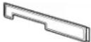 | ☐ Top Bracket 1 | |
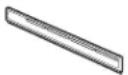 | ☐ Bottom Bracket 1 | |
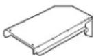 | ☐ Upper Duct 1 | |
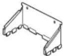 | ☐ Rear Duct 1 | |
 | ☐ 4 mm x 14 mm 22 requiredRound-Head 2 extraScrews | required |
 | ☐ 4 mm x 14 mm 4 requiredFlat-Head 2 extraScrews | required |
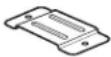 | ☐ Anti-Tip Brace 1 | |
 | ☐ Anti-Tip Bracket 1 | |
 | ☐ Template | 1 |
NOTE: This kit has extra screws to prevent the technician from spending extra time locating a replacement screw during installation.
TOOLS YOU WILL NEED
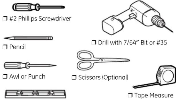
Level
□ 1 CUTOUT DIMENSIONS
| Models | 27" | 30" |
| Height | 1834" | 1834" |
| Width | 24'' ± 116" | 24'' ± 116" |
| Depth (min.)* | 2112" or 23" | 2112" or 23" |
* Min. depth with 120V–60 Hertz grounded power receptacle outside cabinet 21½" Min. depth with 120V–60 Hertz grounded power receptacle inside cabinet 23"
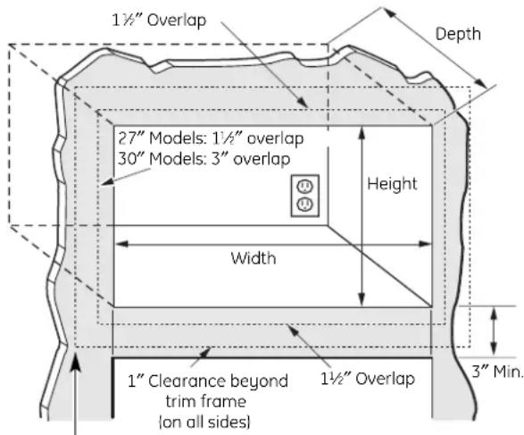
Bottom of trim kit must be minimum of 36" from floor
WARNING — This trim kit uses air flow from the top, bottom and sides of the trim frame. Blocking the air flow can cause the microwave to function improperly and may cause damage to the microwave.
Allow a 1" clearance beyond the edge of the trim frame to provide proper air flow.
☐ 1 CUTOUT DIMENSIONS (CONT.)
On 27" models, allow 1½" on all sides for overlap of the trim frame over the edges of the cutout.
On 30" models, allow 1½" at the top and bottom and 3" on each side for overlap of the trim frame over the edges of the cutout.
FOR INSTALLATION ABOVE A BUILT-IN OVEN:
Microwave oven should be installed on a 3/8" plywood base and supported by 2×4 or 1×2 equivalent runners on all sides. Base must be capable of supporting a minimum of 100 lbs (45.3 kg).
☐ 2 INSTALL THE ANTI-TIP BRACE
A Draw a line on the cutout floor at the center of the cutout, and extend the line 1/2" down the face of the cabinet.
B Fold or cut the front edge of the template, along the front guide line. Place the template flush along the front edge of the cutout floor, aligning the center line of the template with the center line of the cutout floor. Mark the centers of the two screw holes with an awl or center punch for the anti-tip brace location as shown.
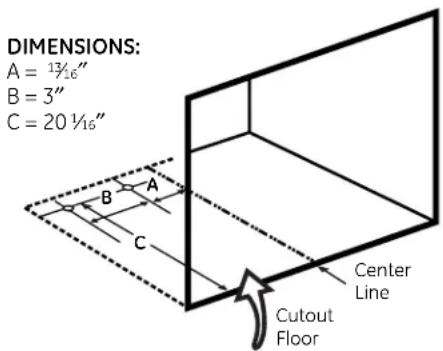
C Remove the template and drill two holes for the anti-tip brace.
D Install the anti-tip brace onto the cutout floor using two round-head screws.
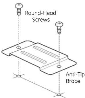
1^=0.3~m
1" = 2.5 cm
INSTALL BOTTOM DUCT ASSEMBLY TO MICROWAVE OVEN
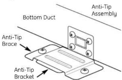
A Fasten the anti-tip bracket to the bottom duct using four round-head screws.
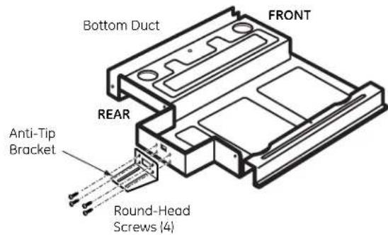
B Install the rear duct to the bottom duct with one round-head screw.
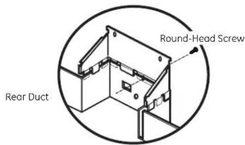
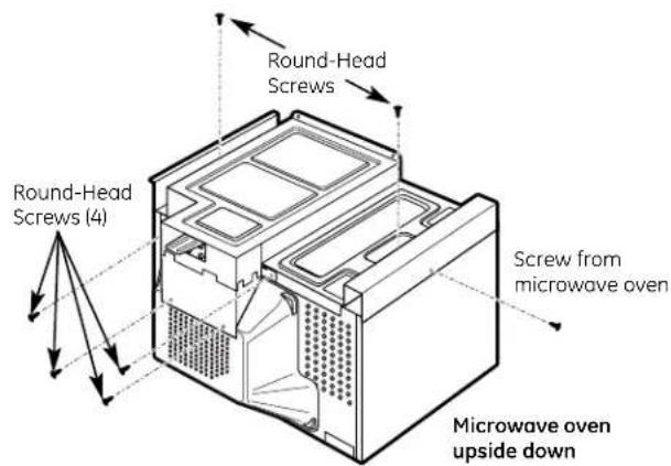
C Remove all loose items, including the turntable and turntable support, from the microwave oven. Carefully turn the oven upside down. Remove one screw from microwave oven cabinet. Place the bottom duct assembly on the microwave oven bottom and fasten with six round-head screws and the screw just removed from the microwave oven. Turn the microwave oven right side up, being careful not to bend the bottom duct flange.
☐ 4 INSTALL UPPER DUCT AND TOP BRACKET
A Remove two screws from back of the microwave oven. Peel off the adhesive backing from the upper duct and secure it to the microwave oven by pressing it firmly down on duct. Fasten the upper duct with the two screws just removed from the microwave oven.
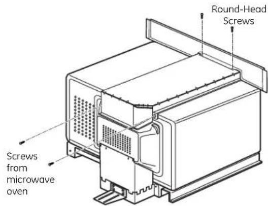
B Place the top bracket on top of the upper duct, with the opening on the top bracket lined up with the opening on the duct. Attach the top bracket to the upper duct using two round-head screws.
☐ 5 INSTALL MICROWAVE OVEN INTO CABINET
A Slide the microwave oven part way into the cabinet opening.
B Plug in the microwave oven.
C The anti-tip bracket must be flat to the
D Center the microwave oven within the cutout opening.
□6 CHECK LEVELING
Check the leveling by placing a level at the front and sides of the microwave. It may be necessary to add wood shims under the bottom duct to level the microwave front to back or side to side.
natural_image
Line drawing of hands operating a kitchen appliance with buttons and a digital display (no text or symbols)☐ 7 INSTALL THE BOTTOM BRACKET AND SECURE THE TOP BRACKET
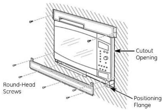
A Drill pilot holes through the three holes on the front flange of the bottom duct assembly.
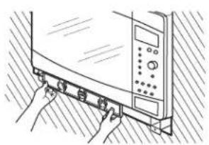
B Hold the bottom bracket against the front flange of the bottom duct assembly, lining up the three holes in the bottom bracket with the three holes in the bottom duct. Screw in three round-head screws. Drill pilot holes through the two holes in the tabs on the sides of the bottom bracket. Screw in two round-head screws.
C Drill pilot holes through the side holes in the top bracket. Secure the top bracket to the cabinet using two round-head screws.
MFL38290502
49-40553-1
10-07 JR
Printed in Korea
☐ 8 INSTALL THE TRIM FRAME
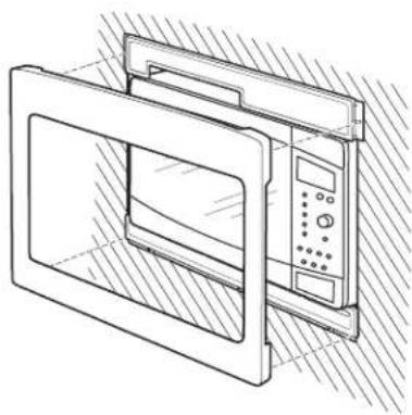
A Place the trim frame over the microwave oven with the vent openings at the bottom.
B Press the trim frame into the opening until all sides snap into place.
natural_image
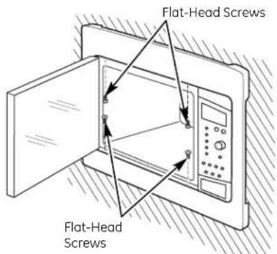
Line drawing of a microwave oven with control panel and door, no text or symbols presentC Open the microwave oven door. Secure the trim frame using four flat-head screws (two on the inside top and two on the inside bottom).
☐ 9 REPLACE ANY LOOSE ITEMS
A Your trim kit is now fully installed. Replace the turntable and turntable support that were removed from the inside of the microwave oven.
B Keep these installation instructions and extra screws for future reference and need. Do not place them in the microwave oven.
C Replace house fuse or close circuit breaker to restore power at the service panel.
LISEZ ATTENTIVEMENT CES INSTRUCTIONS
ET CONSERVEZ-LES.
OUTILS NÉCESSAIRES

□ Tournevis Phillips n° 2
natural_image
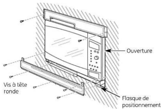
Line drawing of hands installing or adjusting a wall-mounted device component (no text or symbols visible)□ MONTAGE DU SUPPORT INFÉRIEUR ET FIXATION DU SUPPORT SUPÉRIEUR
natural_image
Technical line drawing of a microwave oven with control panel and door (no text or symbols)- Installation Instructions
- Built-In Trim Kits
- BEFORE YOU BEGIN
- FOR YOUR SAFETY:
- ☐ 1 CUTOUT DIMENSIONS (CONT.)
- FOR INSTALLATION ABOVE A BUILT-IN OVEN:
- ☐ 2 INSTALL THE ANTI-TIP BRACE
- INSTALL BOTTOM DUCT ASSEMBLY TO MICROWAVE OVEN
- ☐ 4 INSTALL UPPER DUCT AND TOP BRACKET
- ☐ 5 INSTALL MICROWAVE OVEN INTO CABINET
- □6 CHECK LEVELING
- ☐ 7 INSTALL THE BOTTOM BRACKET AND SECURE THE TOP BRACKET
- ☐ 8 INSTALL THE TRIM FRAME
- ☐ 9 REPLACE ANY LOOSE ITEMS
- OUTILS NÉCESSAIRES
- □ MONTAGE DU SUPPORT INFÉRIEUR ET FIXATION DU SUPPORT SUPÉRIEUR
Brand : GE
Model : JX1527CWC
Category : Microwave Oven