
JX2027DMCC - Microwave Oven GE - Free user manual and instructions
Find the device manual for free JX2027DMCC GE in PDF.

| Product type | Built-in microwave oven |
| Brand | GE |
| Model | JX2027DMCC |
| Opening dimensions (27 in) | Height: 16¼ in; Width: 25½ in; Min. depth: 19½ in or 22 in |
| Opening dimensions (30 in) | Height: 16¼ in; Width: 25½ in; Min. depth: 19½ in or 22 in |
| Power supply | 120 V, 60 Hz, 15 A, 3-prong grounded outlet |
| Capacity | Approximately 1.6 cu ft (estimate) |
| Microwave power | 1000 W (estimate) |
| Main functions | Microwave cooking, defrost, timer, turntable, interior light |
| Control | Touch electronic (depending on model) |
| Sound level | Approximately 55 dB (estimate) |
| Net weight | Approximately 20.4 kg (45 lb) (estimate) |
| Cavity material | Stainless steel or enamel |
| Installation type | Built-in, requires trim kit and anti-tip bracket |
| Maintenance and cleaning | Clean with a damp cloth and mild detergent. Avoid abrasives. |
| Safety | Child lock, automatic shutoff, grounding required |
| Available spare parts | Turntable, turntable support, trim kit, ducts |
| Repairability | Repairability index not provided. Repair possible by a professional. |
Frequently Asked Questions - JX2027DMCC GE
User questions about JX2027DMCC GE
0 question about this device. Answer the ones you know or ask your own.
Ask a new question about this device
Download the instructions for your Microwave Oven in PDF format for free! Find your manual JX2027DMCC - GE and take your electronic device back in hand. On this page are published all the documents necessary for the use of your device. JX2027DMCC by GE.
USER MANUAL JX2027DMCC GE
Installation Built-In Trim Kits Instructions JX2027 and JX2030

Questions? In the U.S., call 800.GE.CARES (800.432.2737) or Visit our Website at: ge.com. In Canada, call 1.800.561.3344 or Visit our Website at: GEAppliances.ca.

BEFORE YOU BEGIN
Read these instructions completely and carefully.
- IMPORTANT – Save these instructions for local inspector's use.
- IMPORTANT – Observe all governing codes and ordinances.
- Note to Installer – Be sure to leave these instructions with the Consumer.
- Note to Consumer – Keep these instructions for future reference.
- For easier installation and personal safety, we recommend that two people install this microwave oven.

WARNING — This oven must be plugged into a properly ended 3-hole, 120V receptacle as required by the National Electrical Code e Canadian Electrical Code.
- Do not alter or modify any part of this kit or the oven.
- Unplug the microwave oven before attempting installation of this kit.
- Skill level – Installation of this appliance requires basic mechanical and electrical skills.
• Completion time – 1-3 hours - Proper installation is the responsibility of the installer.
- Product failure due to improper installation is not covered under the Warranty.
- This kit is UL/CSA listed for installation alone or over any GE/GE Profile single electric wall oven. Not for use adjacent to (within 2 feet of) any gas or electric range, cooktop or oven.
- This kit is for use on models: PEB2060DMBB, PEB2060DMWW, PEB2060DMCC, PEB2060SMSS, JEB1860DMBB, JEB1860DMWW, JEB1860DMCC, JEB1860SMSS, PEB206CDNBB, PEB206CSNSS, PEB206CDNWW, JEB186CDNWW, JEB186CDNBB and JEB186CSNSS.
FOR YOUR SAFETY:

WARNING – Before beginning the
installation, switch power off at service panel and lock the service disconnecting means to prevent power from being switched on accidentally. When the service disconnecting means cannot be locked, securely fasten a prominent warning device, such as a tag, to the service panel.
TOOLS YOU WILL NEED

□ Phillips screwdriver

□ Pencil

□ Awl or punch

□ Level
Drill with 764 " bit or #35
Tape measure
□ Scissors (optional)
READ CAREFULLY.
KEEP THESE INSTRUCTIONS.
PARTS INCLUDED
| PART QUANTITY | ||
 | ☐ Trim Frame 1 | |
 | ☐ Bottom Duct 1 | |
| [IWXZ4] | ☐ Side Duct 1 | |
 | ☐ 4 mm × 12 mm 23 Round-Head Screws | (21 required for installation) |
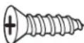 | ☐ 4 mm × 14 mm 6 Flat-Head Screws | (4 required for installation) |
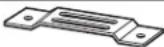 | ☐ Anti-Tip Brace | 1 |
 | ☐ Anti-Tip Bracket | 1 |
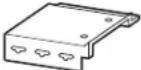 | ☐ Upper Duct | 1 |
 | ☐ Top Bracket | 1 |
 | ☐ Bottom Bracket | 1 |
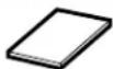 | ☐ Templates | 2 |
NOTE: This kit has extra screws to prevent the technician from spending extra time locating a replacement screw in case they lose one during installation.
□ 1 CUTOUT DIMENSIONS
| Models 27" 30" | ||
| Height 16 | 34" 16 | 34" |
| Width 25 | 12" 25 | 12" |
| Depth (min.)* 19 | 12" or 22" | 1912" or 22" |
* Min. depth with receptacle outside cabinet 19½" Min. depth with receptacle inside cabinet 22" 120 volt-60 Hertz grounded power receptacle
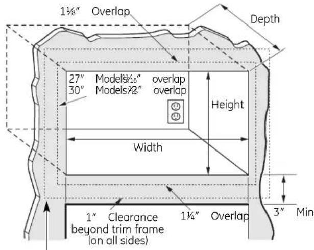
Bottom of trim kit must be minimum of 36" from floor
⚠ WARNING — This trim kit uses air flow from the top, bottom and sides of the trim frame. Blocking the air flow can cause the microwave to function improperly and may cause damage to the microwave.
Allow a 1" clearance beyond the edge of the trim frame to provide proper air flow.
On 27" models, allow 14 " at the top, 116 " on the sides and 114 " at the bottom for overlap of the Trim Frame over the edges of the cutout.
On 30" models, allow 1/8 " at the top, 2/6 " on the sides and 114 " at the bottom for overlap of the Trim Frame over the edges of the cutout.
FOR INSTALLATION ABOVE A BUILT-IN OVEN:
Microwave oven should be installed on a 3/8" plywood base and supported by 2x4 or 1x2 equivalent runners on all sides. Base must be capable of supporting a minimum of 100 lbs (45.3 kg).
☐ 2 INSTALL THE ANTI-TIP BRACE
A Draw a line on the cutout floor at the center of the cutout, and extend the line 1/2" down the face of the cabinet.
B Draw a line on the top front face of the cabinet at the center of the cutout. The line should extend 1/2" up the face of the cabinet. This center line will be used for mounting the top bracket (see step 7).
C Fold or cut the front edge of the template, along the front guide line. Place the template flush along the front edge of the cutout floor, aligning the center line of the template with the center line of the cutout floor. Mark the center positions with an awl or center punch for the anti-tip brace location as shown.
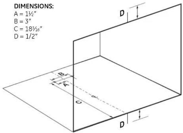
D Drill two holes for the anti-tip brace.
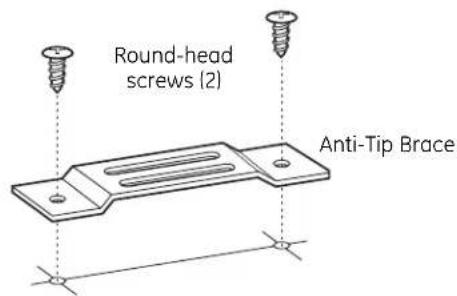
E Install the anti-tip brace onto the cutout floor using two round-head screws.
$$ 1 ^ {\prime} = 0. 3 \mathrm{m} $$
$$ 1 ^ {\prime \prime} = 2. 5 \mathrm{cm} $$
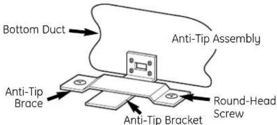
☐ 3 INSTALL ANTI-TIP BRACKET AND BOTTOM DUCT
A Disconnect the microwave oven before proceeding with the installation.
B Fasten the anti-tip bracket to the bottom duct by using four round-head screws.
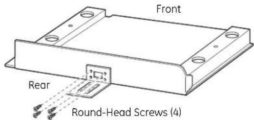
C Remove any loose items inside the microwave oven, including the turntable and turntable support. Carefully turn the microwave upside down.
D Install bottom duct with four round-head screws as shown.
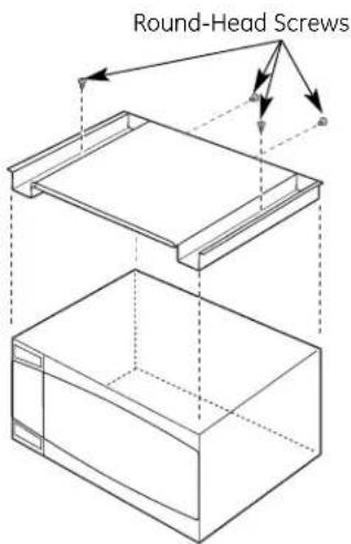
Microwave Oven Upside Down
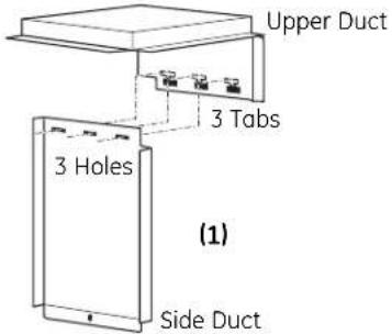
☐ 4 INSTALL SIDE DUCT AND UPPER DUCT
A Connect the side duct to the upper duct as shown.
- Insert projecting tabs of the upper duct into the holes of the side duct.
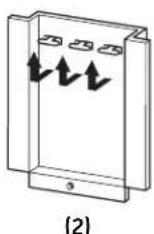
- Bend the tabs up with caution as shown.
NOTE: Remove any oil or dirt on the surface of the microwave oven before the ducts are attached.
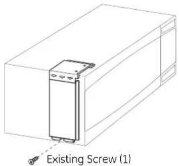
☐ 4 INSTALL SIDE DUCT AND UPPER DUCT (cont.)
B Set the microwave upright, being careful not to bend the front flange. Remove the one existing screw from the left side of the microwave oven.
C As indicated on the supplied template (publication #31-41003-1), fold or cut along the "cut lines" and place the template on top of the microwave oven. By aligning the template with the outside edges of the oven, you will see exactly where to place the upper duct assembly. Peel off the backing from the double-sided tape. Carefully position the side duct and upper duct assembly on the microwave cabinet, aligning with the bottom screw hole. Press down firmly on the ducts. Fasten the duct assembly to the left side of the cabinet with the screw removed above.
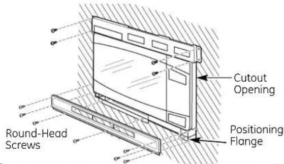
☐ 5 INSTALL MICROWAVE OVEN INTO CABINET
A Slide the microwave oven part way into the cabinet opening.
B Plug in the microwave oven.
C The anti-tip bracket must be flat to the cutout floor to engage correctly with the anti-tip brace as shown. Carefully slide the microwave back, making sure the power cord is not mashed or cut.
D Center the microwave oven within the cutout opening and slide the microwave oven in place, engaging the anti-tip brace.
E Ensure the microwave oven is accurately centered.
6 CHECK LEVELING
Check the leveling by placing a level at the front and sides of the microwave. It may be necessary to add wood shims under the bottom duct to level the microwave front to back or side to side.
natural_image
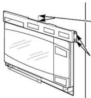
Line drawing of a door handle with hand positioning on one side (no text or symbols)INSTALL THE TOP BRACKET
Ensure that Top Bracket is Level
natural_image
Line drawing of a computer monitor with scroll panels and ventilation slots (no text or symbols)Align Center Lines on Cabinet and Top Bracket
Mark Screw Hole Locations (also on left side of bracket)
A Place the top bracket flange on top of the upper duct with the opening of the top bracket lined up with the opening on the upper duct.
B Align the center line marking on the top bracket with the center line drawn on the top front face of the cabinet at the center of the cutout.
C Ensure the top bracket is level and mark screw hole locations on the cabinet face.
D Drill pilot holes through the side holes in the top bracket. Secure the top bracket to the cabinet using four round-head screws (see illustration in step 8).
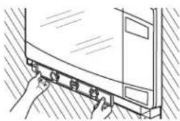
☐8 INSTALL THE BOTTOM BRACKET AND SECURE THE TOP BRACKET
A Drill pilot holes through the three holes on the front flange of the bottom duct assembly.
B Hold the bottom bracket against the front flange of the bottom duct assembly, lining up the three holes in the bottom bracket with the three holes in the bottom duct. Screw in three round-head screws. Drill pilot holes through the four holes in the tabs on the sides of the bottom bracket. Screw in four round-head screws.
9 INSTALL THE TRIM FRAME
A Place the trim frame over the microwave oven with the curved edge at the top.
B Press the trim frame into the opening until all sides snap into place.
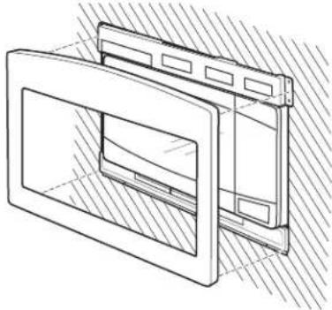
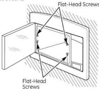
natural_image
Technical line drawing of a mechanical component with hatched shading (no text or symbols)C Open the microwave oven door. Secure the trim frame using four flat-head screws (two on the inside top and two on the inside bottom).
☐ 10 REPLACE ANY LOOSE ITEMS
A Your trim kit is now fully installed. Replace the turntable and turntable support that were removed from the inside of the microwave oven.
B Keep these installation instructions and extra screws for future reference and need. Do not place them in the microwave oven.
C Replace house fuse or close circuit breaker.
| MFL38268402 |
| 49-40552-1 |
LISEZ ATTENTIVEMENT CES INSTRUCTIONS ET CONSERVEZ-LES.
PIÈCES COMPRISES
natural_image
Line drawing of a hand pressing down on a curved mechanical component (no text or symbols)□ MÔNTAGE DU SUPPORT SUPÉRIEUR
natural_image
Line drawing of a window with arrows indicating direction (no text or symbols)natural_image
Technical line drawing of a door frame with hatched shading (no text or symbols)- Installation Built-In Trim Kits Instructions JX2027 and JX2030
- BEFORE YOU BEGIN
- FOR YOUR SAFETY:
- TOOLS YOU WILL NEED
- □ 1 CUTOUT DIMENSIONS
- FOR INSTALLATION ABOVE A BUILT-IN OVEN:
- ☐ 2 INSTALL THE ANTI-TIP BRACE
- ☐ 3 INSTALL ANTI-TIP BRACKET AND BOTTOM DUCT
- ☐ 4 INSTALL SIDE DUCT AND UPPER DUCT
- ☐ 4 INSTALL SIDE DUCT AND UPPER DUCT (cont.)
- ☐ 5 INSTALL MICROWAVE OVEN INTO CABINET
- CHECK LEVELING
- INSTALL THE TOP BRACKET
- ☐8 INSTALL THE BOTTOM BRACKET AND SECURE THE TOP BRACKET
- INSTALL THE TRIM FRAME
- ☐ 10 REPLACE ANY LOOSE ITEMS
- □ MÔNTAGE DU SUPPORT SUPÉRIEUR
Brand : GE
Model : JX2027DMCC
Category : Microwave Oven