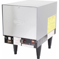
C12 - Heating Hatco - Free user manual and instructions
Find the device manual for free C12 Hatco in PDF.


| Product type | Electric water heater (booster) |
| Brand | Hatco |
| Model | C12 |
| Category | Heating |
| Series | Compact |
| Tank capacity | 23 liters (6 gallons) |
| Flow rate at 22°C rise | 454 liters/hour (120 gallons/hour) |
| Flow rate at 39°C rise | 261 liters/hour (69 gallons/hour) |
| Rated power | 12 kW |
| Available voltages | 208/240 V single-phase or three-phase |
| Dimensions (H × W × D) | 502 × 332 × 525 mm (with adjustable feet 152-178 mm) |
| Weight | 54 kg |
| Tank material | Castone® (10-year limited warranty) |
| Power supply | Electric, terminal block connection |
| Thermostat | Adjustable immersion type with ambient compensation |
| Safety device | High temperature limit switch, thermal/overpressure safety valve |
| Shut-off system | Low water cut-off |
| Included accessories | Safety valve, pressure reducing valve with bypass, two temperature/pressure gauges |
| Installation | By a qualified professional, in compliance with electrical and plumbing codes |
| Maintenance | Exterior cleaning, tank draining, descaling if necessary (water >0.75 GPL) |
| Warranty | 1 year parts and labor, +9 years parts for tank |
Frequently Asked Questions - C12 Hatco
User questions about C12 Hatco
0 question about this device. Answer the ones you know or ask your own.
Ask a new question about this device
Download the instructions for your Heating in PDF format for free! Find your manual C12 - Hatco and take your electronic device back in hand. On this page are published all the documents necessary for the use of your device. C12 by Hatco.
USER MANUAL C12 Hatco
Register Online! (see page 2)
Imperial, Compact, Mini-Compact Series Série Imperial, Compact, Mini-Compact
natural_image
Line drawing of a white industrial machine with ventilation slots and mounting feet (no text or symbols)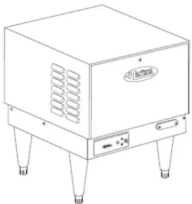
natural_image
Line drawing of a portable electronic device with ventilation slots and mounting legs (no text or symbols)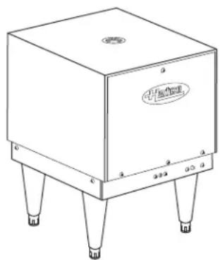
natural_image
Line drawing of a rectangular electronic device with four legs and a top panel, no visible text or symbols.WARNING
Do not operate this equipment unless you have read and understood the contents of this manual! Failure to follow the instructions contained in this manual may result in serious injury or death. This manual contains important safety information concerning the maintenance, use, and operation of this product. If you're unable to understand the contents of this manual, please bring it to the attention of your supervisor. Keep this manual in a safe location for future reference.
English = p 2
ADVERTENCIA
Important Owner Information ....2
Introduction......2
Important Safety Information....3
Model Description....5
All Models....5
Imperial Models "S" Series....5
Compact Models "C" Series 5
Mini-Compact Models "MC" Series 5
Specifications....6
Circuit Breaker and Fused Disconnect Switch Sizes......6
Sizing Chart for Low-Temp Dish Machines 9
Booster Heater Sizing Chart ....10
Capacity Charts....14
Dimensions....15
Installation....17
General....17
Plumbing Installation 18
Electrical-All Sizes and Voltages....23
Operation....24
General....24
Maintenance 25
General....25
Thermostat Adjustment....25
High Temperature Limit Safety Switch 25
Options and Accessories....26
Troubleshooting Guide 27
Limited Warranty....30
Authorized Parts Distributors......Back Cover
IMPORTANT OWNER INFORMATION
Record the model number, serial number, voltage, and purchase date of the unit in the spaces below (specification label located on the unit). Please have this information available when calling Hatco for service assistance.
Model No. ____
Serial No. ____
Voltage
Date of Purchase ____
Register your unit!
Completing online warranty registration will prevent delay in obtaining warranty coverage. Access the Hatco website at www.hatcocorp.com, select the Parts & Service pull-down menu, and click on "Warranty Registration".
Business
Hours: 8:00 AM to 5:00 PM Central Standard Time (CST)
(Summer Hours: June to September—
8:00 AM to 5:00 PM CST Monday–Thursday
8:00 AM to 2:30 PM CST Friday)
Telephone: 800-558-0607; 414-671-6350
e-mail: partsandservice@hatcocorp.com
Fax: 800-690-2966 (Parts and Service)
414-671-3976 (International)
24 Hour 7 Day Parts and Service Assistance available in the United States and Canada by calling 800-558-0607.
Additional information can be found by visiting our web site at www.hatcocorp.com.
INTRODUCTION
Hatco Electric Booster Water Heaters are designed for use with commercial dish machines to boost the temperature of the regularly available hot water, usually 110^-150^ ( 43^-66^ ) up to 180^ ( 82^ ). Water at 180^ ( 82^ ) can be used as sanitizing rinse water in commercial dish machines in accordance with Health Codes, NSF Standard #5 and plumbing codes.
All Hatco Booster Heaters are ready for electrical and plumbing service connections, with an adjustable ambient compensated immersion thermostat(s) and a high temperature limit switch. The service area is accessible from the front of the unit, permitting easy access.
Hatco Electric Booster Water Heaters are products of extensive research and field testing. The materials used were selected for maximum durability, attractive appearance, and optimum performance. Every unit is inspected and tested thoroughly prior to shipment.
This manual provides the installation, safety, and operating instructions for the Hatco Electric Booster Water Heaters. Hatco recommends all installation, operating, and safety instructions appearing in this manual be read prior to installation or operation of the unit.
Safety information that appears in this manual is identified by the following signal word panels:
WARNING
WARNING indicates a hazardous situation which, if not avoided, could result in death or serious injury.
CAUTION
CAUTION indicates a hazardous situation which, if not avoided, could result in minor or moderate injury.
NOTICE
NOTICE is used to address practices not related to personal injury.

Read the following important safety information before using this equipment to avoid serious injury or death and to avoid damage to equipment or property.
WARNING
ELECTRIC SHOCK HAZARD:
- Unit must be installed by qualified, trained installers. Installation must conform to all local electrical and plumbing codes. Installation by unqualified personnel will void the unit warranty and may lead to electric shock or burn, as well as damage to unit and/or its surroundings. Check with local plumbing and electrical inspectors for proper procedures and codes.
- Turn OFF power at fused disconnect switch/circuit breaker and allow unit to cool before performing any cleaning, adjustments, or maintenance.
- Consult a licensed electrical contractor for proper electrical installation conforming to local electrical codes and the National Electrical Code (N.E.C.).
- Unit is not weatherproof. Locate unit indoors where ambient air temperature is a minimum of 70^ (21°C).
- Do not place aftermarket covers on or over booster heater. Doing so can cause temperature and moisture build-up resulting in premature failure and electrical shock.
- This unit must be serviced by qualified personnel only. Service by unqualified personnel may lead to electric shock or burn.
- Use only Genuine Hatco Replacement Parts when service is required. Failure to use Genuine Hatco Replacement Parts will void all warranties and may subject operators of the equipment to hazardous electrical voltage, resulting in electrical shock or burn. Genuine Hatco Replacement Parts are specified to operate safely in the environments in which they are used. Some aftermarket or generic replacement parts do not have the characteristics that will allow them to operate safely in Hatco equipment.
Valves supplied by Hatco are designed for high-temperature commercial operation. Do not substitute Hatco valves with valves designed for domestic water heaters.
Temperature/pressure protective equipment should not be less than a combination temperature/pressure relief valve certified by a nationally recognized testing laboratory that maintains periodic inspection of the production of this equipment and meets the requirements for Relief Valves and Automatic Shutoff Devices for Hot Water Supply Systems, ANSI Z21.22-1979. The temperature/pressure relief valve must be marked with a minimum set pressure not to exceed the marked hydrostatic test pressure of the booster heater as noted on the unit specifications.
EXPLOSION HAZARD: Do not store or use gasoline or other flammable vapors or liquids in the vicinity of this or any other appliance.
WARNING
FOR INSTALLING PRESSURE AND TEMPERATURE RELIEF VALVES IN ACCORDANCE WITH AMERICAN NATIONAL STD. Z21.22-1979. Combination pressure and temperature relief valves with extension thermostats must be installed so that the temperature-sensing element is immersed in the water within the top 6" (152 mm) of the tank. They must be installed directly in a tank tapping. Combination pressure and temperature relief valves that do not have extension elements must be mounted directly in a tank tapping located within the top 6" (152 mm) of the tank, and shall be adequately insulated and located so as to assure isolation from ambient conditions that are not indicative of stored water temperature. TO AVOID WATER DAMAGE OR SCALDING DUE TO VALVE OPERATION, DRAIN PIPE MUST BE CONNECTED TO VALVE OUTLET AND RUN TO A SAFE PLACE OF DISPOSAL. Discharge line must be as short as possible and be the same size as the valve discharge connection throughout its entire length. Drain line must pitch downward from the valve and must terminate between 1-1/2" (38 mm) and 6" (152 mm) above the floor drain where any discharge will be clearly visible. The drain line shall terminate plain, not threaded, with material serviceable for temperatures up to 250°F (121°C) or greater. Excessive length, over 30' (9.1 m), or use of more than four elbows can cause a restriction and reduce the discharge capacity of the valve. No shut-off valve shall be installed between the relief valve and tank, or in the drain line. Valve lever must be tripped periodically to assure that waterways are clear. This device is designated for emergency safety relief and shall not be used as an operating control. The valves are set to relieve at 150 psi (1034 kPa) or when water temperature reaches 210°F (99°C). Read tag on valve for additional information.
Use only plumbing material suitable for a minimum water temperature of 200^ F ( 93^ C). Materials used must meet National Sanitation Foundation (NSF) specifications and all local plumbing codes and regulations.
Units are equipped with a high temperature limit safety switch that will shut off the power if the unit overheats. Contact an Authorized Hatco Service Agent if the high temperature limit safety switch cannot be reset or continues to trip.
Install booster water heater in a horizontal position with the base parallel to the floor and the inlet connection at the lowest point. Improper installation could create an unsafe condition.
Do not connect booster water heaters to domestic (consumer) dish machines or other domestic utilized equipment. This booster may damage domestic equipment.

Read the following important safety information before using this equipment to avoid serious injury or death and to avoid damage to equipment or property.
WARNING
This product contains fiberglass, a product known to the state of California to cause cancer, birth defects, or other reproductive harm.
Install booster water heater as close as possible to a commercial dish machine. Employ re-circulation if distance between water heater and dish machine exceeds National Sanitation Foundation (NSF) specifications of five (5) linear feet (1524 mm).
Follow standard welding safety and operational procedures when attaching sliderails to bottom of dishtable.
Make sure the dishtable is strong enough to support the weight of the heater AND water when installing with slide mounting brackets.
Refer to the BOOSTER HEATER SIZING CHART in this manual to ensure proper sizing and avoid personal injury and/or damage to the booster heater.
It is essential to recognize that even though a water heater may be properly installed initially and approved, there always exists the possibility that unknowing individuals might alter or change the installation in a manner that would render it unsafe. Therefore, it is important that all safety programs provide some mechanism to assure that these installations are inspected periodically.
This unit has no "user-serviceable" parts. If service is required on this unit, contact an Authorized Hatco Service Agent or contact the Hatco Service Department at 800-558-0607 or 414-671-6350; fax 800-690-2966; or International fax 414-671-3976.
CAUTION
BURN HAZARD:
• Water in unit is very hot. Wear protective gloves and proper attire when operating to avoid injury.
- Valves supplied by Hatco are designed for high temperature commercial operation. Do not substitute Hatco valves with valves designed for domestic water heaters.
Do not use anti-siphon valves on incoming water line.
Check valves on incoming water line is not recommended. Damages caused by the use of check valves on unit will not be covered by warranty.
Do not connect booster heater directly to a boiler or furnace coil or any other uncontrolled temperature source. The booster heater thermostat could be damaged causing unit to overheat.
Do not connect an expansion tank of any type to booster heater water lines.
CAUTION
Hatco requires that two temperature/pressure gauges (Hatco P/N 03.01.003.00) be installed to ensure proper operation. Install one in the supply line before the pressure reducing valve and one in the outlet line as close to the booster heater as possible. This provides a visual check of the water temperature and pressure before and after the water heater.
If water supply pressure to the booster inlet is over 20 psi (138 kPa) during flow, install pressure reducing valve with built-in bypass (Hatco P/N 03.02.004.00) for proper operation of dish machine rinse nozzles.
NOTE: The pressure reducing valve must be the type equipped with a high pressure bypass, as supplied by Hatco.
DO NOT turn on power to the booster heater until tank has been filled with water and all air has been vented through the dish machine rinse nozzles. Heating elements will burn out in seconds if operated when not immersed in water.
NOTICE
Always drain booster heater with power to the unit off or element burnout could occur.
Use dielectric couplings when connecting dissimilar metals, such as galvanized to copper. This will prevent electrolysis or premature plumbing damage.
Do not turn or adjust outlet water connection on all Large Compact Series units (C-24 to C-57).
Do not turn or adjust inlet water connection on Compact Series Booster Heaters or internal water flow will change.
Do not back out or loosen any pipe fittings or leaks may occur.
Do not lay unit on the side with the control panel. Damage to the unit could occur.
Incoming water in excess of 3 grains of hardness per gallon (GPG) (0.75 grains of hardness per liter [GPL]) must be treated and softened before being supplied to booster heater(s). Water containing over 3 GPG (0.75 GPL) will decrease efficiency, increase energy use, and reduce the operating life of the unit through increased lime build-up. Product failure caused by liming or sediment buildup is not covered under warranty.
Do not use deionized water. Deionized water will shorten the life of water reservoir and heating element.
Units are voltage-specific. Refer to specification label for electrical requirements before beginning installation. Connecting unit to incorrect power supply will void product warranty and may damage unit.
All Models
Hatco Electric Water Booster Heaters are available in three models: Imperial, Compact, and Mini-Compact. All standard models include a booster heater with low-water cut-off system, temperature/pressure relief valve, pressure reducing valve with built-in high pressure bypass, two temperature/pressure gauges and a high temperature limit safety switch.
Imperial Models "S" Series
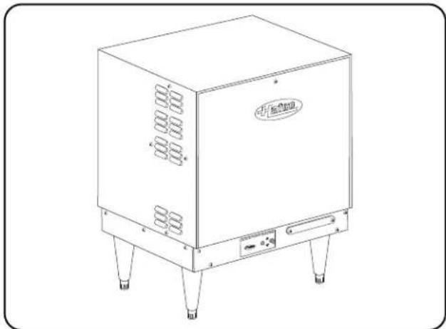
Hatco Imperial models feature a Castone ^® tank with a 10 year limited tank warranty, a Power ON/OFF (I/O) switch, an indicator light and 6" (152 mm) legs. Imperial units have a capacity of 16 gallons (61 liters) and provide up to 573 gallons per hour (gph) (2169 liters per hour [lph]) of sanitizing rinse water based on a 40°F (22°C) temperature rise.
natural_image
Line drawing of a rectangular industrial machine with cooling unit and mounting legs (no text or symbols)Imperial Model
Compact Models "C" Series
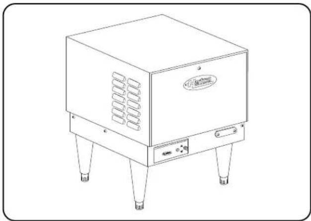
Hatco Compact models feature a Castone® tank with a 10 year limited tank warranty, a Power ON/OFF (I/O) switch, an indicator light and either 6" (152 mm) legs or slide mounting brackets for mounting under a dish table. Compact units have a capacity of 6 gallons (23 liters) and provide up to 573 gph (2169 lph) of sanitizing rinse water based on a 40°F (22°C) temperature rise.
natural_image
Line drawing of a portable industrial machine with four legs and ventilation slots (no text or symbols)Compact Model
Mini-Compact Models "MC" Series
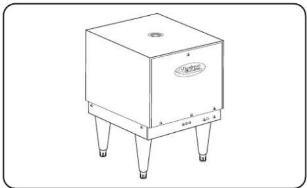
Hatco Mini-Compact models feature a stainless steel tank with a 10 year limited tank warranty and 6" (152 mm) legs. Mini-Compact units have a capacity of 3.2 gallons (12 liters) and provide up to 172 gph (651 lph) of sanitizing rinse water based on a 40°F (22°C) temperature rise. Ideal for either hot water sanitizing or point-of-use hot water dispensing.
NOTE: Mini-Compact models can be configured with an optional Power ON/OFF (I/O) switch.
natural_image
Line drawing of a square industrial control box with four legs and a top panel, no text or symbols present.Mini-Compact Model
Circuit Breaker and Fused Disconnect Switch Sizes — 4 to 12 kW
| kW Voltage Phase | L1 L2 L3 | Breaker or Fuse Size | Copper Wire Size Conduit Size | ||||
| 4 208 1 19 19 -- 30 10 1/2" (13 mm) | |||||||
| 240 1 17 17 -- 30 10 1/2" (13 mm) | |||||||
| 480 1 | 8 | 8 | -- 15 14 1/2" (13 mm) | ||||
| 5 208 1 24 24 -- 30 10 1/2" (13 mm) | |||||||
| 240 1 21 21 -- 30 10 1/2" (13 mm) | |||||||
| 480 1 10 10 -- 15 14 1/2" (13 mm) | |||||||
| 6 208 1 29 29 -- 40 8 | 1/2" (13 mm) | ||||||
| 208 3 14 25 14 | 40 8 | 1/2" (13 mm) | |||||
| 240 1 25 25 -- 40 8 | 1/2" (13 mm) | ||||||
| 240 3 13 22 13 | 30 10 1/2" (13 mm) | ||||||
| 380 | 3 | 9.2 | 9.2 | 9.2 | 15 | 14 | 1/2" (13 mm) |
| 480 | 3 | 6 | 11 | 6 | 15 | 14 | 1/2" (13 mm) |
| 600 | 3 | 5.7 | 5.7 | 5.7 | 15 | 14 | 1/2" (13 mm) |
| 7 208 1 34 34 -- 50 8 | 1/2" (13 mm) | ||||||
| 208 3 17 29 17 | 40 8 | 3/4" (19 mm) | |||||
| 240 1 29 29 -- 40 8 | 1/2" (13 mm) | ||||||
| 240 3 15 25 15 | 40 8 | 1/2" (13 mm) | |||||
| 380 | 3 | 11.4 | 11.4 | 11.4 | 15 | 14 | 1/2" (13 mm) |
| 480 | 3 | 7 | 13 | 7 | 20 | 12 | 1/2" (13 mm) |
| 600 | 3 | 6.7 | 6.7 | 6.7 | 15 | 14 | 1/2" (13 mm) |
| 9 208 1 43 43 -- 60 6 | 1/2" (13 mm) | ||||||
| 208 3 22 38 22 | 50 8 | 1/2" (13 mm) | |||||
| 240 1 38 38 -- 50 8 | 1/2" (13 mm) | ||||||
| 240 3 19 33 19 | 50 8 | 1/2" (13 mm) | |||||
| 380 | 3 | 13.3 | 13.3 | 13.3 | 20 | 12 | 1/2" (13 mm) |
| 480 | 3 | 9 | 16.3 | 9 | 30 | 12 | 1/2" (13 mm) |
| 600 | 3 | 8.7 | 8.7 | 8.7 | 15 | 14 | 1/2" (13 mm) |
| 9.9 | 208 | 1 | 47.5 | 47.5 | -- | 60 | 6 |
| 208 | 3 | 27.5 | 27.5 | 27.5 | 40 | 8 | |
| 10.4 | 208 | 3 | 28.8 | 28.8 | 28.8 | 40 | 8 |
| 10.5 | 208 1 51 51 -- 70 4 | 3/4" (19 mm) | |||||
| 208 3 29 29 29 | 40 8 | 1/2" (13 mm) | |||||
| 240 1 44 44 -- 60 6 | 1/2" (13 mm) | ||||||
| 240 | 3 | 25.3 | 25.3 | 25.3 | 40 | 8 | |
| 480 | 3 | 12.6 | 12.6 | 12.6 | 20 | 12 | |
| 600 3 10 10 10 | 15 14 1/2" (13 mm) | ||||||
| 11.4 | 240 | 1 | 47.5 | 47.5 | -- | 60 | 6 |
| 240 | 3 | 27.5 | 27.5 | 27.5 | 40 | 8 | |
| 480 | 3 | 13.7 | 13.7 | 13.7 | 20 | 12 | |
| 12 | 208 | 1 | 58 | 58 | -- | 90 | 3 |
| 208 3 33 33 33 | 50 8 | 1/2" (13 mm) | |||||
| 240 1 50 50 -- 70 4 | 3/4" (19 mm) | ||||||
| 240 3 29 29 29 | 40 8 | 1/2" (13 mm) | |||||
| 380 | 3 | 19.1 | 19.1 | 19.1 | 30 | 10 | |
| 480 | 3 | 14.5 | 14.5 | 14.5 | 20 | 12 | |
| 600 | 3 | 11.6 | 11.6 | 11.6 | 15 | 14 | |
The shaded area contains electrical information for International models only.
NOTE: 250 kcmil maximum wire size for terminal block.
Circuit Breaker and Fused Disconnect Switch Sizes — 13.5 to 30 kW
| kW Volts Phase | Amp Draw | Breaker or Fuse Size | Copper Wire Size Conduit Size | |||||
| L1 L2 L3 | ||||||||
| 13.5 208 | 1 65 65 - 90 3 | 1 | "(25 mm) | |||||
| 208 | 1 38 38 38 50 8 | 1/2" (13 mm) | ||||||
| 240 | 1 | 56.3 | 56.3 | -- | 90 | 3 | 1" (25 mm) | |
| 240 | 1 33 33 33 50 8 | 1/2" (13 mm) | ||||||
| 480 | 1 | 16.3 | 16.3 | 16.3 | 30 | 10 | 1/2" (13 mm) | |
| 600 | 1 13 13 13 20 | 12 | 1/2" (13 mm) | |||||
| 15 | 208 | 1 72 72 - 90 3 | 1 | "(25 mm) | ||||
| 208 | 3 | 41.7 | 41.7 | 41.7 | 60 | 6 | 3/4" (19 mm) | |
| 240 | 1 | 62.5 | 62.5 | -- | 90 | 3 | 1" (25 mm) | |
| 240 | 3 | 36.1 | 36.1 | 36.1 | 50 | 8 | 1/2" (13 mm) | |
| 380 | 3 | 23.0 | 23.0 | 23.0 | 30 | 10 | 1/2" (13 mm) | |
| 480 | 3 | 18.1 | 18.1 | 18.1 | 30 | 10 | 1/2" (13 mm) | |
| 600 | 3 | 14.5 | 14.5 | 14.5 | 20 | 12 | 1/2" (13 mm) | |
| 17.25 | 208 | 3 | 47.9 | 47.9 | 47.9 | 60 | 6 | 3/4" (19 mm) |
| 18 | 208 | 1 | 86.5 | 86.5 | -- | 125 | 1 | 1-1/4" (32 mm) |
| 240 | 1 | 75 | 75 | -- | 100 | 3 | 1" (25 mm) | |
| 240 | 3 | 43.4 | 43.4 | 43.4 | 60 | 6 | 3/4" (19 mm) | |
| 380 | 3 | 27.3 | 27.3 | 27.3 | 40 | 8 | 1/2" (13 mm) | |
| 480 | 3 | 21.7 | 21.7 | 21.7 | 30 | 10 | 1/2" (13 mm) | |
| 600 | 3 17 17 17 30 | 10 | 1/2" (13 mm) | |||||
| 24 | 208 | 1 | 115.4 | 115.4 | -- | 150 | 1/0 | 1-1/4" (32 mm) |
| 208 | 3 | 66.7 | 66.7 | 66.7 | 90 | 3 | 1" (25 mm) | |
| 240 | 1 | 100 | 100 | -- | 125 | 1 | 1-1/4" (32 mm) | |
| 240 | 3 | 57.8 | 57.8 | 57.8 | 90 | 3 | 1-1/4" (32 mm) | |
| 380 | 3 | 38.0 | 38.0 | 38.0 | 50 | 8 | 1/2" (13 mm) | |
| 480 | 3 | 29.9 | 29.9 | 29.9 | 40 | 8 | 1/2" (13 mm) | |
| 600 | 3 23 23 23 30 | 10 | 1/2" (13 mm) | |||||
| 27 | 208 | 1 | 129.8 | 129.8 | -- | 175 | 2/0 | 1-1/4" (32 mm) |
| 208 | 3 | 75 | 75 | 75 | 100 | 3 | 1" (25 mm) | |
| 240 | 1 | 112.5 | 112.5 | -- | 150 | 1/0 | 1-1/4" (32 mm) | |
| 240 | 3 65 65 65 90 3 | 1 | "(25 mm) | |||||
| 380 | 3 | 38.1 | 38.1 | 38.1 | 50 | 8 | 1/2" (13 mm) | |
| 480 | 3 | 32.5 | 32.5 | 32.5 | 50 | 8 | 1/2" (13 mm) | |
| 600 | 3 26 26 26 40 8 | 1/2" (13 mm) | ||||||
| 30 | 208 | 1 | 144 | 144 | -- | 200 | 3/0 | 1-1/2" (38 mm) |
| 208 | 3 | 83.3 | 83.3 | 83.3 | 125 | 1 | 1-1/4" (32 mm) | |
| 240 | 1 | 125 | 125 | -- | 175 | 2/0 | 1-1/2" (38 mm) | |
| 240 | 3 | 72.3 | 72.3 | 72.3 | 100 | 3 | 1" (25 mm) | |
| 380 | 3 | 45.7 | 45.7 | 45.7 | 60 | 6 | 3/4" (19 mm) | |
| 480 | 3 36 36 36 50 8 | 1/2" (13 mm) | ||||||
| 600 | 3 | 28.9 | 28.9 | 28.9 | 40 | 8 | 1/2" (13 mm) | |
Wire size is based on THHN wire for branch circuit protection at .91 derate factor. Circuit breakers and fused disconnects are to be mounted remote and wired by contractor. Sizes are based on the 2002 NEC table 310-16. Conduit size based on conductors plus ground wire sizing per Table C1 from Appendix C.
Only 6, 7 and 9 kW models can be field converted to single or three phase (open delta on 3 phase). Check wiring diagram supplied with the unit when converting the phase of the unit. Larger branch circuit required than for balanced 3 phase of equal kW. Balanced 3 phase available, consult factory.
Circuit Breaker and Fused Disconnect Switch Sizes — 36 to 57 kW
| kW Volts Phase | Amp Draw | Breaker or Fuse Size | Copper Wire Size Conduit Size | |||||
| L1 L2 L3 | ||||||||
| 36 208 1 173 173 -- 225 4/0 1-1/2" (38 mm) | ||||||||
| 208 3 100 100 100 125 1 | 1-1/4" (32 mm) | |||||||
| 240 1 150 150 -- 200 3/0 1-1/2" (38 mm) | ||||||||
| 240 | 3 | 86.7 | 86.7 | 86.7 | 125 | 1 | 1-1/4" (32 mm) | |
| 380 | 3 | 54.7 | 54.7 | 54.7 | 70 | 4 | 1" (25 mm) | |
| 480 | 3 | 43.3 | 43.3 | 43.3 | 60 | 6 | 3/4" (19 mm) | |
| 600 | 3 | 34.7 | 34.7 | 34.7 | 50 | 8 | 1/2" (13 mm) | |
| 39 | 208 | 1 | 187.5 | 187.5 | -- | 250 | 250 kcmil | 2" (51 mm) |
| 208 3 108 108 108 150 1/0 1-1/4" (32 mm) | ||||||||
| 240 | 1 | 163.5 | 163.5 | -- | 225 | 4/0 | 2" (51 mm) | |
| 240 3 | 94 94 94 | 125 1 | 1-1/4" (32 mm) | |||||
| 380 | 3 | 59.3 | 59.3 | 59.3 | 90 | 3 | 1" (25 mm) | |
| 480 | 3 | 47 | 47 | 47 | 60 | 6 | 3/4" (19 mm) | |
| 600 | 3 | 37.6 | 37.6 | 37.6 | 50 | 8 | 1/2" (13 mm) | |
| 40 | 208 | 3 | 61.6 | 61.6 | 61.6 | 90 | 3 | 1" (25 mm) |
| 40.5 | 208 | 3 | 112.5 | 112.5 | 112.5 | 150 | 1/0 | 1-1/4" (32 mm) |
| 240 | 3 | 97.5 | 97.5 | 97.5 | 125 | 1 | 1-1/4" (32 mm) | |
| 480 | 3 | 48.8 | 48.8 | 48.8 | 70 | 4 | 1" (25 mm) | |
| 600 | 3 | 39 | 39 | 39 | 50 | 8 | 3/4" (19 mm) | |
| 45 208 3 125 125 125 175 2/0 1-1/2" (38 mm) | ||||||||
| 240 1 188 188 -- 250 | 250 kcmil | 2" (51 mm) | ||||||
| 240 3 108 108 108 150 1/0 1-1/4" (32 mm) | ||||||||
| 380 | 3 | 68.6 | 68.6 | 68.6 | 90 | 3 | 1" (25 mm) | |
| 480 | 3 | 54 | 54 | 54 | 70 | 4 | 1" (25 mm) | |
| 600 | 3 | 43.4 | 43.4 | 43.4 | 60 | 6 | 3/4" (19 mm) | |
| 54 208 3 150 150 150 200 3/0 | 2" (51 mm) | |||||||
| 240 3 130 130 130 175 2/0 1-1/2" (38 mm) | ||||||||
| 380 3 | 82 82 82 | 125 1 | 1-1/4" (32 mm) | |||||
| 480 | 3 | 65 | 65 | 65 | 90 | 3 | 1" (25 mm) | |
| 600 | 3 | 52 | 52 | 52 | 70 | 4 | 1" (25 mm) | |
| 57 | 208 | 3 | 158.4 | 158.4 | 158.4 | 200 | 3/0 | 2" (51 mm) |
| 240 | 3 | 137.3 | 137.3 | 137.3 | 175 | 2/0 | 1-1/2" (38 mm) | |
| 380 | 3 | 86.7 | 86.7 | 86.7 | 125 | 1 | 1-1/4" (32 mm) | |
| 480 | 3 | 68.6 | 68.6 | 68.6 | 90 | 3 | 1" (25 mm) | |
| 600 | 3 | 54.9 | 54.9 | 54.9 | 70 | 4 | 1" (25 mm) | |
The shaded area contains electrical information for International models only.
Wire size is based on THHN wire for branch circuit protection at .91 derate factor. Circuit breakers and fused disconnects are to be mounted remote and wired by contractor. Sizes are based on the 2002 NEC table 310-16. Conduit size based on conductors plus ground wire sizing per Table C1 from Appendix C.
NOTE: 250 kcmil maximum wire size for terminal block.
WARNING
ELECTRIC SHOCK HAZARD: Consult a licensed electrical contractor for proper electrical installation conforming to local electrical codes and the National Electrical Code (N.E.C.).
Sizing Chart for Low-Temp Dish Machines
| BOOSTERS RATED AT 30°F (16°C) RISE Compact ImperialDish Machine Model Number Booster Booster | ||
| American Dish AH, AH-3D, AH-3D-S, AHC, AHC-3D, AHC-3D-S, ET-A, ET-AF, ET-AH,Service ET-A-M, ET-AH-M, ET-A-3, ET-AH-3, L-90-3D, L-90-3D-K, L-90-3D-K-S,L-90-3D-S, L-90-3DC, L-90-3DC-K, L-90-3DC-S, L-90-3DW,L-90-3DW-K, L-90-3DW-K-S, L-90-3DW-S, L-90-3DWC, L-90-3DWC-K,L-90-3DWC-K-S, L-90-3DWC-S, WH, WHC......C-4......S-6A-3D, A-3D-S, A, AC, AC-3D, AC-3D-S, AH-B, ET-AF-3, ET-AF-M, HT-25,L-60-3D, L-60-3D-K, L-60-3D-K-S, L-60-3D-S, L-60-3DC, L-60-3DC-K,L-60-3DC-K-S, L-60-3DC-S, L-60-3DW, L-60-3DW-K, L-60-3DW-K-S,L-60-3DW-S, L-60-3DWC, L-60-3DWC-K, L-60-3DWC-S,L-72-3D, L-72-3D-K, L-72-3D-K-S, L-72-3D-S, L-72-3DC, L-72-3DC-K,L-72-3DC-K-S, L-72-3DC-S, L-72-3DW, L-72-3DW-K, L-72-3DW-K-S,L-72-3DWC-S, L-72-3DWC, L-72-3DWC-K, L-72-3DWC-K-S, L-72-3DWC-S,W, WC......C-5......S-6A-B, AD-25, SS-25, 5-AH, 5-AHS......C-6......S-6AF, AF-3D, AF-3D-S, AF-B, AFC, AFC-3D, AFC-3D-S, AFW, AFWC, 5, 5-S......C-7......S-7ADC-44, ADC-66, 5-AG, 5-AGS, 5-CD-LF, 5-CD-RF......C-9......S-9 | ||
| Blakeslee | U21-C......C-4......S-6D-8-LT......C-6......S-6DD-8-LT, R-CC64-LT, R-EE-LT......C-12......S-12Series XF-EE-LT, XF-PEE-LT, XF-LL-LT, XF-PLL-LT, XF-MM-LT, XF-PMM-LT,XF-EEE-LT, XF-LLL-LT, XF-MMM-LT......C-13......S-13Series R-L-LT, R-PL-LT, R-M-LT, R-PM-LT, F-L-LT, F-PL-LT, F-M-LT,F-PM-LT (single tank)......C-36......S-36Series "R" & "F"-CC-LT, -EE-LT, -LL-LT, -MM-LT, -LLL-LT, -MMM-LT, -PCC-LT,-PEE-LT, -PLL-LT, -PMM-LT (multi-tank)......C-24......S-24Series XF-L-LT, XF-PL-LT, XF-M-LT, XF-PM-LT (single tank)......C-54......S-54Series XF-PEE-LT, XF-PLL-LT, XF-PMM-LT, XF-EEE-LT, XF-LLL-LT,XF-MMM-LT (multi-tank)......C-36......S-36FA (Flight-A-Round) and RA (Rack-A-Round) use comparable "F" listing. | |
| Champion | ULD, ULF......C-6......S-6DLF......C-13......S-13KL44, KL66......C-36......S-36 | |
| CMADish Machines | A-1, AH-1, C-1, VAC-1, A-3, AH-3, C-3, L-1C, VAC-3, VAC-4, VAC-5, L-1XA-2, AH-1, AH-2, AH-3, B-3, C-1, C-2, C-3, EVA-1, EVA-2, EVA-3, EVA-4,EVA-5, VAC-2......C-6......S-6B-1......C-7......S-7B-2......C-9......S-9CMA-44L with tank heater, CMA-66LCVA-1, CVA-2, CVA-3, CVA-4......C-6......S-6CVA-5......C-7......S-7 | |
| Hobart | LX-18C, LX-30C, LX-40C, WM-5C, SR24CLT-1......C-6......S-6AM-14, AM-14C......C-7......S-7C44A, CRS66A, CPW80A......C-27......S-27FT-800......C-30......S-30 | |
| Jackson | Conserver 24LT, 200LT, ES1000, (Ecolab/Jackson)......C-4......S-6Conserver 1, Conserver XL, ES2000 (Ecolab/Jackson)......C-9......S-9Conserver 2, Conserver XL2, ES4000 (Ecolab/Jackson)......C-15......S-15AJ-44, AJ-66, AJ-80......C-18......S-18 | |
| Knight Equipment LTD. | KLE-112-HL......C-5......S-6KLE-117i, KLE-117c, KLE-175GT, KLE-175GTM......C-9......S-9KLE-235d......C-13......S-13KLE-175GT Corner, KLE-175GTM Corner......C-12......S-12 | |
Booster Heater Sizing Chart
| Dish Machine Model Number Temperature Rise Temperature Rise | ELECTRIC ELECTRICCOMPACT BOOSTER IMPERIAL BOOSTER | ||||
| 40°F (22°C) | 70°F (39°C) | 40°F (22°C) | 70°F (39°C) | ||
| Adamation | CSL-1390, CA-2, CA-3, CA-4, SLAP 44 | C-39 | (2)C-36 | S-39 | (2)S-36 |
| CA, CA-1 | C-54 | (2)C-45 | S-54 | (2)S-45 | |
| Alvey | FLC-10, SL-2S | --- | --- | S-6 | S-9 |
| FLC-12, CL-1, CL-1 Turntable, SA-5A | --- | --- | S-7 | S-12 | |
| FL-2S | --- | --- | S-9 | S-13 | |
| KS-70, KS70M SB | --- | --- | S-9 | S-15 | |
| SL-2D | --- | --- | S-13 | S-18 | |
| FLC-36 | --- | --- | S-15 | S-27 | |
| KS-88 | --- | --- | S-18 | S-30 | |
| KS-70-N, KS-88-N | --- | --- | S-39 | (2)S-40 | |
| American Dish Service | AF-ES, AFC-ES | C-4 | C-7 | C-4 | C-7 |
| HT-25 | C-7 | C-12 | S-7 | S-12 | |
| ACD-44, ADC-66 | C-12 | C-24 | S-12 | S-24 | |
| Blakeslee | UC-21A, UC-21B | C-4 | C-4 | S-6 | S-6 |
| UC-21 | C-6 | C-12 | S-6 | S-12 | |
| D-8 | C-9 | C-13 | S-9 | S-13 | |
| D-9 | C-12 | C-17 | S-12 | S-17 | |
| Series "R" & "F"-CC, -EE, -LL, -MM, -LLL, -MMM, -PCC,-PEE, -PLL, -PMM (multi-tank) with suffix "LC" | C-13 | C-24 | S-13 | S-24 | |
| Series XF-EE, XF-LL | C-17 | C-30 | S-17 | S-30 | |
| Series XF-LL, XF-PLL, XF-MM, XF-PMM, XF-EEE, XF-LLL,XF-MMM (multi-tank) with suffix "LC" | C-17 | C-30 | S-17 | S-30 | |
| DD-8 | C-18 | C-30 | S-18 | S-30 | |
| Series F-E, FA-EE, FA-PEE, FA-LL, FA-PLL, FA-MM,FA-PMM, F-EEE, FA-EEE, FA-LLL, FA-MMM, F-PE | C-30 | C-54 | S-30 | S-54 | |
| Series R-L, R-PL, R-M, R-PM, F-L, F-PL, F-M,F-PM (single tank) | C-36 | C-54 | S-36 | S-54 | |
| Series XF-L, XF-PL, XF-M, XF-PM, (single tank) | (2)C-36 | --- | (2)S-36 | --- | |
| Series R-E, R-PE, XF-PEE, XF-PLL, XF-PMM, XF-EEE,XF-LLL, XF-MMM (multi-tank) | C-45 | (2)C-30 | S-45 | (2)S-30 | |
| FA (Flight-A-Round) and RA (Rack-A-Round) use comparable "F" listing,XF-EE, XF-EE-LT (with LT suffix) | C-17 | C-36 | S-17 | S-36 | |
| Champion | U-H1, UH-200, UH-200B, U-HB | C-4 | C-6 | S-6 | S-6 |
| UL-100, UH-100B, UH-170B, UH-200B, DH-2000 | C-6 | C-9 | S-6 | S-9 | |
| UL-150 | C-4 | C-7 | S-6 | S-7 | |
| UH-150, UH-150B, UH-100, UH-100B, DHB-VS | C-5 | C-9 | S-6 | S-9 | |
| D-H1, D-HB, D-H1T, D-HBT | C-6 | C-12 | S-6 | S-12 | |
| 44 DRWS, 66 DRPWWS, 80 DRHDPWWS, 70 DRFFPWWS | C-9 | C-13 | S-9 | S-13 | |
| PP-28 | C-9 | C-15 | S-9 | S-15 | |
| D-H1C, D-H1TC | C-9 | C-18 | S-9 | S-18 | |
| 44DR, 66DRPW, 80DRHDFW, 70DRFFPW, 54DR | C-12 | C-24 | S-12 | S-24 | |
| 66WSPW, 44-WS, 66-WS, 64, 90FFPW, 100HDPW,86 PW, 84, 106 PW,120 HDPW, 110 FFPW | C-13 | C-24 | S-13 | S-24 | |
| UC-CW6-WS | C-24 | C-36 | S-24 | S-36 | |
| US-CW8-WS | C-24 | C-39 | S-24 | S-39 | |
| 44, 66 PW, 70FFPW, 80HDPW, 54, 76PW, 80FFPW,90HDPW | C-24 | C-45 | S-24 | S-45 | |
| 40-KB, 40-KB-2-2, 40-KFWB, 40-KPRB, 40KPRB-2-2,40KPRB-2-3, 60-KB, 60-KB-2-2, 60-KFWB, 60-KFWB-2-2,60-KPRB, 60-KPRB-2-3, 64KB, 64-KB Corner, 64-KPRB,64-KPRB Corner, 64 Modular, 86 Modular | C-30 | C-54 | S-30 | S-54 | |
| 44-KB, 44-KB Corner, 44-KPRB, 44-KPRB Corner, 54-KB,54-KB Corner, 54-KPRB, 54-KPRB Corner, 44 Modular,66 PW Modular, UC** Series 6' Center, UC-C4 | C-36 | C-57 | S-36 | S-57 | |
| UC-CW4 | C-36 | (2)C-36 | S-36 | (2)S-36 | |
| UC-C | C-45 | (2)C-36 | S-45 | (2)S-36 | |
| UC**CW Series 6' Center | C-45 | (2)C-39 | S-45 | (2)S-40 | |
| W-6-WS, W6 | C-45 | (2)C-45 | S-45 | (2)S-40 | |
| CMA | |||||
| Dish Machines | CMA-180 | C-7 | C-12 | S-7 | S-12 |
| CMA-44/66 | C-24 | C-36 | S-24 | S-36 | |
| CMA-44H with tank heater, CMA-66H | C-36 | C-45 | S-36 | S-45 | |
| EST-44/66 | C-12 | C-24 | S-12 | S-24 | |
| Hobart | AM-15F | C-4 | C-6 | S-6 | S-6 |
| LXIC, LXiGC, LX-18C, LX-30C, LX-40C, AM-15F | C-4 | C-7 | S-6 | S-6 | |
| LX-30, SR24, SR24H | C-4 | C-7 | S-6 | S-7 | |
| LX-18, AM-14F, AM-15, AM-15T | C-5 | C-9 | S-6 | S-9 | |
| WM-5C | C-6 | C-9 | S-6 | S-9 | |
| WM-5 (without sump heater) | C-7 | C-12 | S-7 | S-12 | |
| AM-14T, AM-14TC | C-7 | C-12 | S-7 | S-12 | |
| AM-14, AM-14C | C-9 | C-12 | S-9 | S-12 | |
| AM-12, AM-12C* | C-9 | C-12 | S-9 | S-12 | |
| UW-50 | --- | --- | S-15 | S-24 | |
| or Opti-Rinse C44A, CRS-66A, CCS-66A, CPW-80A, C54A, CRS-76A, CCS-76A, CPW-90A, C64A, CRS-86A, CCS-86A, CPW-100A, C-88A, CRS-110A, CCS-110A, CPW-124A | C-15 | C-27 | S-15 | S-27 | |
| C-54A, CRS-76A, CPW-90A, CCS-76A | C-39 | (2)C-36 | S-30 | (2)S-36 | |
| C-44A, CRS-66A, CCS-66A, CPW-80A, C-64A, CRS-86A, CCS-86A, CPW-100A | C-30 | C-54 | S-30 | S-54 | |
| C-88A, CRS-110A, CPW-124A, CCS-110A | C-36 | C-54 | S-36 | S-54 | |
| or Opti-Rinse C44AW, CRS-66AW, CCS-66AW, CPW-80AW | C-9 | C-15 | S-9 | S-15 | |
| C-44AW, CRS-66AW, CPW-80AW, CCS-66AW | C-12 | C-24 | S-12 | S-24 | |
| C-44, CRS-66, CPW-80 | C-36 | C-54 | S-36 | S-54 | |
| C-54, CRS-76, CPW-90 | C-54 | (2)C-39 | S-54 | (2)S-39 | |
| C-64W, CRS-86W, CPW-100W, C-88W, CRS-110W, CPW-124W, CCS-86W | C-24 | C-36 | S-24 | S-36 | |
| C-64, CRS-86, CPW-100 | C-45 | (2)C-36 | S-45 | (2)S-36 | |
| FT800W, FT-900W | C-24 | C-39 | S-24 | S-39 | |
| FT-600, FT-700 | C-54 | (2)C-39 | S-54 | (2)S-39 | |
| FT800 | C-39 | (2)C-39 | S-39 | (2)S-39 | |
| FT900 | C-36 | C-57 | S-36 | S-57 | |
| FT800S, FT-900S | C-39 | (2)C-36 | S-39 | (2)S-36 | |
| UTW-28, UTW-28C | --- | --- | S-18 | S-36 | |
| FRC and FR (Fast Rack Series) use comparable "C" line listing. | |||||
| Insinger | GS 302, GS-14 | C-4 | C-4 | S-6 | S-6 |
| 45SA-5 | C-4 | C-7 | S-6 | S-7 | |
| Commander 18-5 Series, CS-5, CS-5C, CS-5CH, CS-5H, Ensign | C-6 | C-12 | S-6 | S-12 | |
| Commander 18-6 Series | C-6 | C-12 | S-6 | S-12 | |
| Admiral 44-4, 66-4, Speeder 64, 86-3, Clipper (all) | C-24 | C-36 | S-24 | S-39 | |
| Admiral 44-4, 66-4, (Built-In) | ABB-15-8 | ABB-27-8 | --- | --- | |
| 135-20, 185-20, 250-20, 60-20, 85-20, R-106-2 | C-24 | C-25 | S-24 | S-45 | |
| Century (all) | C-24 | C-45 | S-24 | S-45 | |
| Trac 878 | C-24 | C-36 | S-24 | S-36 | |
| Century 14, Clipper RC-##-RPW-W | C-24 | C-39 | S-24 | S-39 | |
| Super 106-2, Trac 321, Trac 321-2/RPW | C-27 | C-45 | S-27 | S-45 | |
| Defender Flight Machine | C-30 | C-54 | S-30 | S-54 | |
| Defender | C-36 | C-54 | S-36 | S-54 | |
| Master RC 3-tank Flight Machine | C-15 | C-27 | S-15 | S-27 | |
| Master RC 4-tank Flight Machine | C-36 | C-57 | S-36 | S-57 | |
| CA-3 | --- | --- | S-9 | S-24 | |
| DA-3 | --- | --- | (2)S-9 | (2)S-24 | |
| For outdated models, consult factory for correct booster. | |||||
* Hobart Model AM-12 with serial no. 12-067-357 or below and model AM-12C with serial no. 12-067-537 or below require slightly larger booster than listed. 'C' Models with serial no. 85-1041605 or greater use Opti-Rinse.
Shaded area indicates older models prior to Opti-Rinse.
Booster Heater Sizing Chart (continued)
| Dish machine Model Number Temperature Rise Temperature Rise | ELECTRIC ELECTRICCOMPACT BOOSTER IMPERIAL BOOSTER | ||||
| 40°F (22°C) | 70°F (39°C) | 40°F (22°C) | 70°F (39°C) | ||
| Jackson | JP-24, JP-24B, JP-24F, JP-24BF | C-4 | C-6 | S-6 | S-6 |
| 24B Series | --- | C-4 | --- | S-6 | |
| 10AB, 10APRB | --- | C-5 | --- | S-6 | |
| 44CE*, 66 CERPW | C-30 | C-54 | S-30 | S-54 | |
| 54CE, 76 CERPW | C-36 | (2)C-30 | S-36 | (2)S-30 | |
| 64CE, 86 CERPW | C-27 | C-39 | S-27 | S-39 | |
| 100 | C-12 | C-24 | S-12 | S-24 | |
| 100B, 100PRB, 150B, 150PRB | --- | C-9 | --- | S-9 | |
| 150 | C-12 | C-18 | S-12 | S-18 | |
| 200 | C-7 | C-12 | S-7 | S-12 | |
| 200B | --- | C-6 | --- | S-6 | |
| Tempstar, Tempstar SDS, Tempstar HH | C-6 | C-12 | S-6 | S-12 | |
| TS-44, TS-66 | C-24 | C-36 | S-24 | S-36 | |
| AJ-44, AJ-66, AJ-80, WH-44, ES-4400,ES-6600 (Ecolab/Jackson) | C-24 | C-45 | S-24 | S-45 | |
| AJ-54, AJ-76, AJ-90 | C-36 | (2)C-36 | S-36 | (2)S-36 | |
| AJ-64, AJ-86, AJ-100 | C-24 | C-39 | S-24 | S-39 | |
| *Model #44CE w/SN1999 or below requires larger booster than listed. | |||||
| KnightEquipment LTD. | KLE-112-HL | C-7 | C-12 | S-7 | S-12 |
| Meiko | K-44, K-66, K-80 | C-24 | C-36 | S-24 | S-36 |
| K-54, K-76, K-90, K-64, K-86, K-100 | C-24 | C-45 | S-24 | S-45 | |
| Metalwash/Intedge | FW4 | C-12 | C-18 | S-12 | S-18 |
| RS-30A, RS-28L | --- | --- | S-15 | S-24 | |
| RT-74, RT-60, RT-42B, RT-42BC | --- | --- | S-27 | S-40 | |
| RS-2R | --- | --- | S-30 | S-45 | |
| Stero | ER-44, ER-44-10, ER-66S, ER-76S, ER-76SC | C-15 | C-24 | S-15 | S-24 |
| ER-64, ER-86S, ER-94S, ER-94SC | C-15 | C-24 | S-15 | S-24 | |
| SCT-44-10-LW, SCT-44-LW, SCT-66S-LW, SCT-76S-LW, SCT-76SC-LW, SCT-90S-LW | C-15 | C-24 | S-15 | S-24 | |
| SC-1-2-4-LW, SC-1-6-4-LW, SC-2-4-LW, SC-5-2-4-LW, SC-5-6-4-LW, SC-6-4-LW | C-15 | C-24 | S-15 | S-24 | |
| SCT-64, SCT-86S, SCT-94S, SCT-94SC | C-24 | C-45 | S-24 | S-45 | |
| SCT-108S, SCT-108SC, SCT-76, SCT-94SM | C-30 | C-54 | S-30 | S-54 | |
| SC-6-4, SCT-44, SCT-44-10, SCT-66S, SCT-76S, SCT-76SC, SCT-90S | C-36 | C-54 | S-36 | S-54 | |
| SCT-120S, SCT-120SC, SCT-120SM, SCT-150SM | C-36 | C-57 | S-36 | S-57 | |
| STW-110, SC-1-2-7-4, SC-1-6-3-4, SC-1-6-7-4, SC-2-7-4, SC-5-2-7-4, SC-5-6-3-4, SC-5-6-7-4, SC-6-3-4, SC-6-7-4 | C-30 | C-54 | S-30 | S-54 | |
| SC-1-2-4, SC-1-6-4, SC-2-4, SC-5-2-4, SC-5-6-4 | C-36 | (2)C-57 | S-36 | (2)S-57 | |
| SCT-44-10-SC-1-3-4, SCT-44-10-3-4, SCT-44-SC-1-3-4, SCT-44-SC-3-4, SCT-54-SC-1-3-4, SCT-54-SC-3-4, SCT-76S-SC-3-4 | C-36 | C-54 | S-36 | S-54 | |
| STPC (Four tank) | C-24 | C-45 | S-24 | S-45 | |
| STPCW (Four tank) | C-27 | C-45 | S-27 | S-45 | |
| STPC | C-30 | C-54 | S-27 | S-54 | |
| STPCW | C-36 | (2)C-30 | S-36 | (2)S-30 | |
| SD-2RA, SDRA, SDRA-PACK | C-12 | C-18 | S-12 | S-18 | |
| U-31-A, U-31-AC | --- | --- | S-24 | S-45 | |
| U-31-A2 | --- | --- | (2)S-24 | (2)S-45 | |
| STBUW-1 | C-45 | (2)C-36 | S-45 | (2)S-36 | |
| SC-2-3-4, SC-5-2-3-4 | C-30 | C-45 | S-30 | S-45 | |
| SC20-1 (low temp) | C-12 | --- | S-12 | --- | |
| SC20-2 (low temp) | C-12 | C-24 | S-12 | S-24 | |
| SC-2-8, SC-2-9, SC-1-2-8, SC-5-6-8, SC-6-8, SC-6-9, SC-1-6-8 | |||||
| SC-5-6-9, SC-5-2-9, SC-1-6-9, SC-5-2-8 (low temp) | C-18 | C-36 | S-18 | S-36 | |
This selector chart is based on 40^ F ( 22^ C) and 70^ F ( 39^ C) temperature rises, 20 psi flow pressure, and minimum rinse cycle timer setting in NSF listing.
All booster heaters are rated at 100% of the capacity of the dish machines as recommended by the National Sanitation Foundation. Where make-up water for wash tank is provided from final rinse supply, chart recommendations are based upon this additional demand (not over 2 GPM) as required by NSF.
NOTE: All sizings shown are that of the dish machine manufacturers. Hatco Corporation is not responsible for incorrect sizing applications.
Capacity — Imperial "S" Series
| Model kW | 40°F (22°C) | Rise 70°F (39°C) | Rise Storage Capacity | Shipping Weight | |
| S-6 | 6 | 60 gph (227 lph) | 34 gph (129 lph) | 16 gallons (61 liters) | 200 lbs. (91 kg) |
| S-7 | 7 | 70 gph (265 lph) | 40 gph (151 lph) | 16 gallons (61 liters) | 200 lbs. (91 kg) |
| S-9 | 9 | 90 gph (341 lph) | 52 gph (197 lph) | 16 gallons (61 liters) | 200 lbs. (91 kg) |
| S-12 | 12 | 120 gph (454 lph) | 69 gph (261 lph) | 16 gallons (61 liters) | 200 lbs. (91 kg) |
| S-13 | 13.5 | 135 gph (511 lph) | 77 gph (292 lph) | 16 gallons (61 liters) | 200 lbs. (91 kg) |
| S-15 | 15 | 151 gph (572 lph) | 86 gph (326 lph) | 16 gallons (61 liters) | 200 lbs. (91 kg) |
| S-17 | 17.2 | 173 gph (655 lph) | 99 gph (375 lph) | 16 gallons (61 liters) | 200 lbs. (91 kg) |
| S-18 | 18 | 181 gph (685 lph) | 103 gph (390 lph) | 16 gallons (61 liters) | 200 lbs. (91 kg) |
| S-24 | 24 | 241 gph (912 lph) | 138 gph (522 lph) | 16 gallons (61 liters) | 214 lbs. (97 kg) |
| S-27 | 27 | 271 gph (1026 lph) | 155 gph (587 lph) | 16 gallons (61 liters) | 214 lbs. (97 kg) |
| S-30 | 30 | 301 gph (1139 lph) | 172 gph (651 lph) | 16 gallons (61 liters) | 214 lbs. (97 kg) |
| S-36 | 36 | 361 gph (1367 lph) | 206 gph (780 lph) | 16 gallons (61 liters) | 214 lbs. (97 kg) |
| S-39 | 39 | 391 gph (1480 lph) | 224 gph (848 lph) | 16 gallons (61 liters) | 214 lbs. (97 kg) |
| S-40 | 40.5 | 407 gph (1541 lph) | 232 gph (878 lph) | 16 gallons (61 liters) | 224 lbs. (102 kg) |
| S-45 | 45 | 452 gph (1711 lph) | 258 gph (977 lph) | 16 gallons (61 liters) | 224 lbs. (102 kg) |
| S-54 | 54 | 542 gph (2052 lph) | 310 gph (1174 lph) | 16 gallons (61 liters) | 224 lbs. (102 kg) |
| S-57 | 57 | 573 gph (2169 lph) | 326 gph (1234 lph) | 16 gallons (61 liters) | 224 lbs. (102 kg) |
Capacity — Compact "C" Series
| Model kW | 40°F (22°C) | Rise 70°F (39°C) | Rise Storage Capacity | Shipping Weight | |
| C-4 | 4 | 40 gph (151 lph) | 23 gph (87 lph) | 6 gallons (23 liters) | 105 lbs. (48 kg) |
| C-5 | 5 | 50 gph (189 lph) | 29 gph (110 lph) | 6 gallons (23 liters) | 105 lbs. (48 kg) |
| C-6 | 6 | 60 gph (227 lph) | 34 gph (129 lph) | 6 gallons (23 liters) | 118 lbs. (54 kg) |
| C-7 | 7 | 70 gph (265 lph) | 40 gph (151 lph) | 6 gallons (23 liters) | 118 lbs. (54 kg) |
| C-9 | 9 | 90 gph (341 lph) | 52 gph (197 lph) | 6 gallons (23 liters) | 118 lbs. (54 kg) |
| C-12 | 12 | 120 gph (454 lph) | 69 gph (261 lph) | 6 gallons (23 liters) | 120 lbs. (54 kg) |
| C-13 | 13 | 135 gph (511 lph) | 77 gph (292 lph) | 6 gallons (23 liters) | 120 lbs. (54 kg) |
| C-15 | 15 | 151 gph (572 lph) | 86 gph (326 lph) | 6 gallons (23 liters) | 120 lbs. (54 kg) |
| C-17 | 17 | 173 gph (655 lph) | 99 gph (375 lph) | 6 gallons (23 liters) | 120 lbs. (54 kg) |
| C-18 | 18 | 181 gph (685 lph) | 103 gph (390 lph) | 6 gallons (23 liters) | 120 lbs. (54 kg) |
| C-24 | 24 | 241 gph (912 lph) | 138 gph (522 lph) | 6 gallons (23 liters) | 142 lbs. (64 kg) |
| C-27 | 27 | 271 gph (1026 lph) | 155 gph (587 lph) | 6 gallons (23 liters) | 142 lbs. (64 kg) |
| C-30 | 30 | 301 gph (1139 lph) | 172 gph (651 lph) | 6 gallons (23 liters) | 142 lbs. (64 kg) |
| C-36 | 36 | 361 gph (1367 lph) | 206 gph (780 lph) | 6 gallons (23 liters) | 142 lbs. (64 kg) |
| C-39 | 39 | 391 gph (1480 lph) | 224 gph (848 lph) | 6 gallons (23 liters) | 142 lbs. (64 kg) |
| C-45 | 45 | 452 gph (1711 lph) | 258 gph (977 lph) | 6 gallons (23 liters) | 142 lbs. (64 kg) |
| C-54 | 54 | 542 gph (2052 lph) | 310 gph (1174 lph) | 6 gallons (23 liters) | 142 lbs. (64 kg) |
| C-57 | 57 | 573 gph (2169 lph) | 326 gph (1234 lph) | 6 gallons (23 liters) | 142 lbs. (64 kg) |
Capacity — Mini-Compact "MC" Series
| Model kW | 40°F (22°C) | C) Rise 70°F (39°C) | Rise Storage Capacity | Shipping Weight | |
| MC-10 9.9 | 99 gph (375 lph) | 57 gph (216 lph) | 3.2 gallons (12 liters) | 48 lbs (22 kg) | |
| MC-10.5 | 10.4 | 104 gph (393 lph) | 60 gph (227 lph) | 3.2 gallons (12 liters) | 48 lbs. (22 kg) |
| MC-11 | 11.4 | 114 gph (432 lph) | 65 gph (248 lph) | 3.2 gallons (12 liters) | 48 lbs. (22 kg) |
| MC-15 | 15 | 150 gph (568 lph) | 86 gph (326 lph) | 3.2 gallons (12 liters) | 48 lbs. (22 kg) |
| MC-17 | 17.25 | 173 gph (655 lph) | 99 gph (375 lph) | 3.2 gallons (12 liters) | 48 lbs. (22 kg) |
Dimensions — Imperial "S" Series
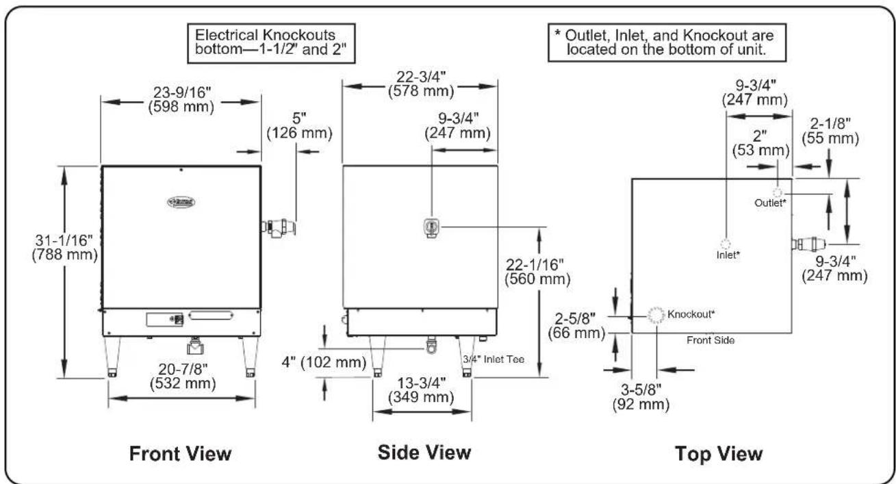
Dimensions — Compact "C" Series 4 to 18 kW
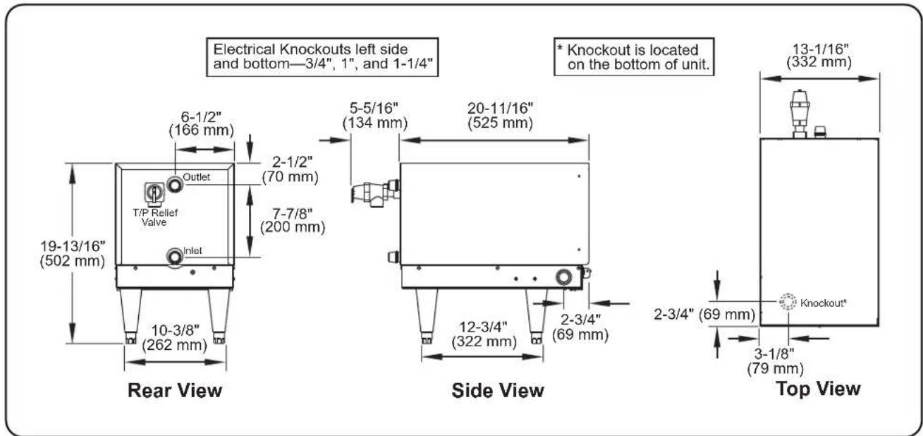
Dimensions — Compact "C" Series 24 to 57 kW
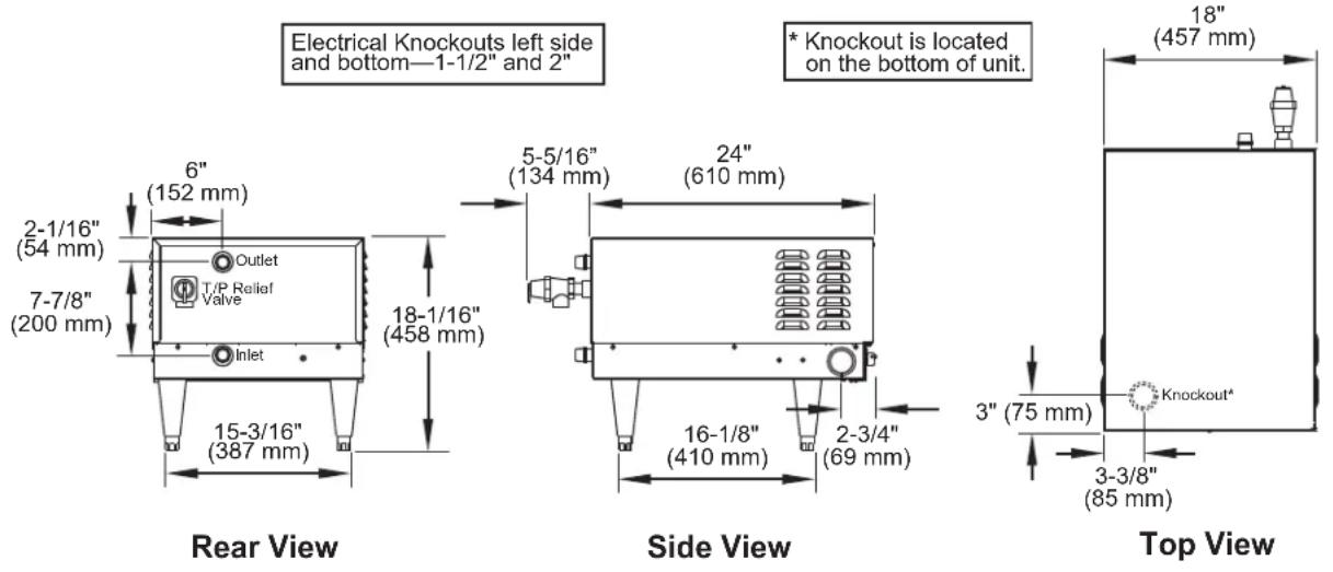
Electrical Knockouts left side and bottom—1-1/2" and 2"
Dimensions — Mini-Compact "MC" Series
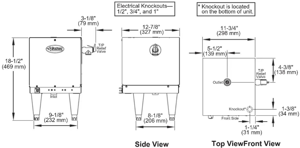
Electrical Knockouts—1/2", 3/4", and 1"
* Knockout is located on the bottom of unit.
General
Booster Heaters are shipped with most components pre-assembled. Care should be taken when unpacking shipping carton to avoid damage to unit and components enclosed. Components are shipped with the heater unit.
WARNING
ELECTRIC SHOCK HAZARD:
- Unit must be installed by qualified, trained installers. Installation must conform to all local electrical and plumbing codes. Installation by unqualified personnel will void the unit warranty and may lead to electric shock or burn, as well as damage to unit and/or its surroundings. Check with local plumbing and electrical inspectors for proper procedures and codes.
- Unit is not weatherproof. Locate unit indoors where ambient air temperature is a minimum of 70^ (21°C).
- Do not place aftermarket covers on or over booster heater. Doing so can cause temperature and moisture build-up resulting in premature failure and electrical shock.
EXPLOSION HAZARD: Do not store or use gasoline or other flammable vapors or liquids in the vicinity of this or any other appliance.
Install booster water heater as close as possible to a commercial dish machine. Employ re-circulation if distance between water heater and dish machine exceeds National Sanitation Foundation (NSF) specifications of five (5) linear feet (1524 mm).
Install booster water heater in a horizontal position with the base parallel to the floor and the inlet connection at the lowest point. Improper installation could create an unsafe condition.
-
Remove the unit from the box.
NOTE: To prevent delay in obtaining warranty coverage, complete online warranty registration. See the IMPORTANT OWNER INFORMATION section for details. -
Remove tape and protective packaging from all surfaces of unit.
-
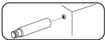
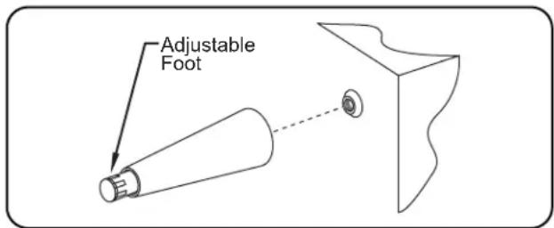
If unit is equipped with legs, carefully lay unit on its side and install the four legs.
natural_image
Simple line drawing of a cylindrical object with a dashed line indicating a connection or alignment (no text or symbols)NOTICE
Do not lay unit on the side with the control panel. Damage to the unit could occur.
NOTE: If unit is not level, use an adjustable wrench to adjust the foot of each leg until unit is level. Each leg is adjustable from 6" (152 mm) to 7" (178 mm).
-
Place the unit in the appropriate location.
-
The location must have a solid foundation along with being clean and dry.
- Adequate front clearance is required to allow for accessibility to the control compartment. Hatco recommends the side clearance be at least 2" (51 mm).
- Location must have adequate clearance to allow for inspection, testing or replacement of pressure and/or temperature relief valve.
• Install the booster heater as close as possible to the commercial dish machine for efficient operation.
WARNING
Make sure the dishtable is strong enough to support the weight of the booster heater and water when installing with slide mounting brackets.
Follow standard welding safety and operational procedures when attaching sliderails to bottom of dishtable.
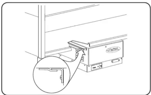
- Install unit under dishtable using mounting slide brackets, if applicable (Compact Series only).
a. Weld slide rails to bottom of dishtable.
b. Using Hatco slide brackets as a template, drill 1/8" (3 mm) holes into the sides of the heater jacket.
c. Attach slide brackets to sides of heater with supplied screws.
d. Slide heater onto slide rails under dishtable.
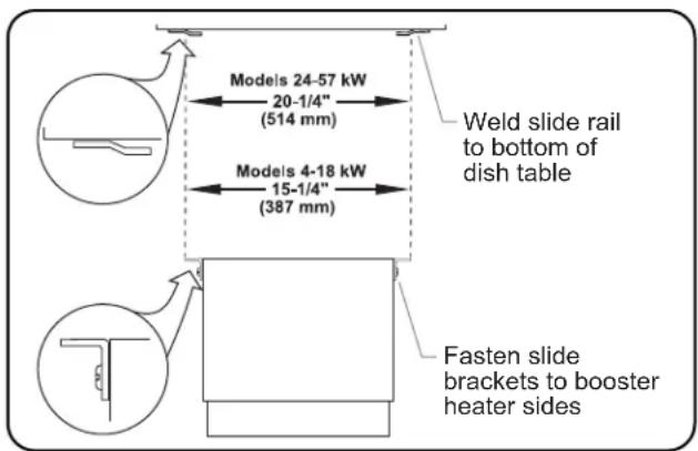
Hanging Support
natural_image
Technical line drawing of a mechanical device with an inset close-up showing a clamping mechanism (no text or symbols)Compact Series Heater Mounted to Dishtable
Plumbing Installation
WARNING
Do not connect booster water heaters to domestic (consumer) dish machines or other domestic utilized equipment. This booster may damage domestic equipment.
Do not connect an expansion tank of any type to booster heater water lines.
Use only plumbing material suitable for a minimum water temperature of 200^ F ( 93^ C). Materials used must meet National Sanitation Foundation (NSF) specifications and all local plumbing codes and regulations.
Refer to the BOOSTER HEATER SIZING CHART in this manual to ensure proper sizing and avoid personal injury and/or damage to the booster heater.
CAUTION
Do not connect booster heater directly to a boiler or furnace coil or any other uncontrolled temperature source. The booster heater thermostat could be damaged causing unit to overheat.
NOTICE
Use dielectric couplings when connecting dissimilar metals, such as galvanized to copper. This will prevent electrolysis or premature plumbing damage.
DO NOT turn or adjust inlet water connection on Compact Series Booster Heaters. Doing so will change the internal water flow.
Do not back out or loosen any pipe fittings. Doing so may cause leaks.
Do not lay unit on the side with the control panel. Damage to the unit could occur.
Incoming water in excess of 3 grains of hardness per gallon (GPG) (0.75 grains of hardness per liter [GPL]) must be treated and softened before being supplied to booster heater(s). Water containing over 3 GPG (0.75 GPL) will decrease efficiency, increase energy use, and reduce the operating life of the unit through increased lime build-up. Product failure caused by liming or sediment buildup is not covered under warranty.
Do not use deionized water. Deionized water will shorten the life of water reservoir and heating element.
NOTE: Product failure caused by liming or sediment buildup is not covered under warranty.
NOTE: A 3/4" union and a drain valve are required for easy servicing.
NOTE: An optional flow restrictor (P/N 03.02.074.00) is available for installation on the water inlet line.
NOTE: Some dish machines require two booster heaters to be plumbed in series (not parallel) to meet the demand. To ensure proper operation, a 30^ F (-1°C) temperature differential must be maintained between the outlet of the first booster heater and the inlet of the second booster heater.
Inlet
Use the following procedure to install the inlet assembly. Refer to the appropriate “Plumbing Connections” diagram in this section for more information.
- Connect the booster water inlet to a hot water supply line from a normal water heater.
- Water temperature from the water heater should be 110°–140°F (43°–60°C) and should not exceed 160°F (71°C). Minimum temperature differential between inlet and outlet should never be less than 30°F (-1°C).
NOTE: Refer to BOOSTER HEATER SIZING CHART for application information.
NOTE: The red mark on the inlet and outlet water pipes of Compact series units must remain in the top most position.
-
Install a shut-off valve (a full opening gate or ball type).
-
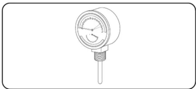
Install one of the temperature/pressure gauges.
- When installing the temperature/pressure gauge, the temperature sensing element must be in the water stream and the gauge must be mounted upright.
NOTE: Tighten gauge during installation by turning the 1/2" brass nut only. DO NOT turn the face of the gauge. Turning the face will cause inaccurate measurements.
CAUTION
Hatco requires that two temperature/pressure gauges (Hatco P/N 03.01.003.00) be installed to ensure proper operation. Install one in the supply line before the pressure reducing valve and one in the outlet line as close to the booster heater as possible. This provides a visual check of the water temperature and pressure before and after the water heater.
NOTE: If a check valve is installed and cannot be removed, install a back pressure relief valve (P/N 03.02.039.00) set at 125 psi (862 kPa) on the incoming line between the pressure reducing valve and the inlet to the booster heater. Discharge must be to open site drain.
natural_image
Line drawing of a pressure gauge with a central shaft and dial (no text or symbols)Temperature/Pressure Gauge
- Install the pressure reducing valve if water pressure available to the booster heater inlet is over 25 psi (172 kPa).
- Set pressure reducing valve at 20 psi (138 kPa) flow pressure.
NOTE: Be sure water flows through the pressure reducing valve in the proper direction. Check directional arrow. Valve will reduce pressure only during flow conditions.
CAUTION
If water supply pressure to the booster inlet is over 20 psi (138 kPa) during flow, install standard pressure reducing valve with built-in bypass (Hatco P/N 03.02.004.00) for proper operation of dish machine rinse nozzles.
NOTE: The pressure reducing valve must be the type equipped with a high pressure bypass, as supplied by Hatco.
NOTE: Optional optional brass pressure reducing valve with built-in bypass (Hatco P/N 03.02.015.00) also available.
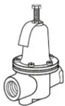
Pressure Reducing Valve
- Install the temperature/pressure relief valve.
• Mini-Compact Series: P/N 03.02.020.00
- Compact and Imperial Series: P/N 03.02.022.00
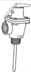
Temperature/Pressure Relief Valve
WARNING
Temperature/pressure protective equipment should not be less than a combination temperature/pressure relief valve certified by a nationally recognized testing laboratory that maintains periodic inspection of the production of this equipment and meets the requirements for Relief Valves and Automatic Shutoff Devices for Hot Water Supply Systems, ANSI Z21.22-1979. The temperature/pressure relief valve must be marked with a minimum set pressure not to exceed the marked hydrostatic test pressure of the booster heater as noted on the unit specifications.
FOR INSTALLING PRESSURE AND TEMPERATURE RELIEF VALVES IN ACCORDANCE WITH AMERICAN NATIONAL STD. Z21.22-1979. Combination pressure and temperature relief valves with extension thermostats must be installed so that the temperature-sensing element is immersed in the water within the top 6" (152 mm) of the tank. They must be installed directly in a tank tapping. Combination pressure and temperature relief valves that do not have extension elements must be mounted directly in a tank tapping located within the top 6" (152 mm) of the tank, and shall be adequately insulated and located so as to assure isolation from ambient conditions that are not indicative of stored water temperature. TO AVOID WATER DAMAGE OR SCALDING DUE TO VALVE OPERATION, DRAIN PIPE MUST BE CONNECTED TO VALVE OUTLET AND RUN TO A SAFE PLACE OF DISPOSAL. Discharge line must be as short as possible and be the same size as the valve discharge connection throughout its entire length. Drain line must pitch downward from the valve and must terminate between 1-1/2" (38 mm) and 6" (152 mm) above the floor drain where any discharge will be clearly visible. The drain line shall terminate plain, not threaded, with material serviceable for temperatures up to 250°F (121°C) or greater. Excessive length, over 30' (9.1 m), or use of more than four elbows can cause a restriction and reduce the discharge capacity of the valve. No shut-off valve shall be installed between the relief valve and tank, or in the drain line. Valve lever must be tripped periodically to assure that waterways are clear. This device is designated for emergency safety relief and shall not be used as an operating control. The valves are set to relieve at 150 psi (1034 kPa) or when water temperature reaches 210°F (99°C). Read tag on valve for additional information.
CAUTION
BURN HAZARD: Valves supplied by Hatco are designed for high temperature commercial operation. Do not substitute Hatco valves with valves designed for domestic water heaters.
Do not use an anti-siphon or check valves on incoming water line.
Plumbing Connections
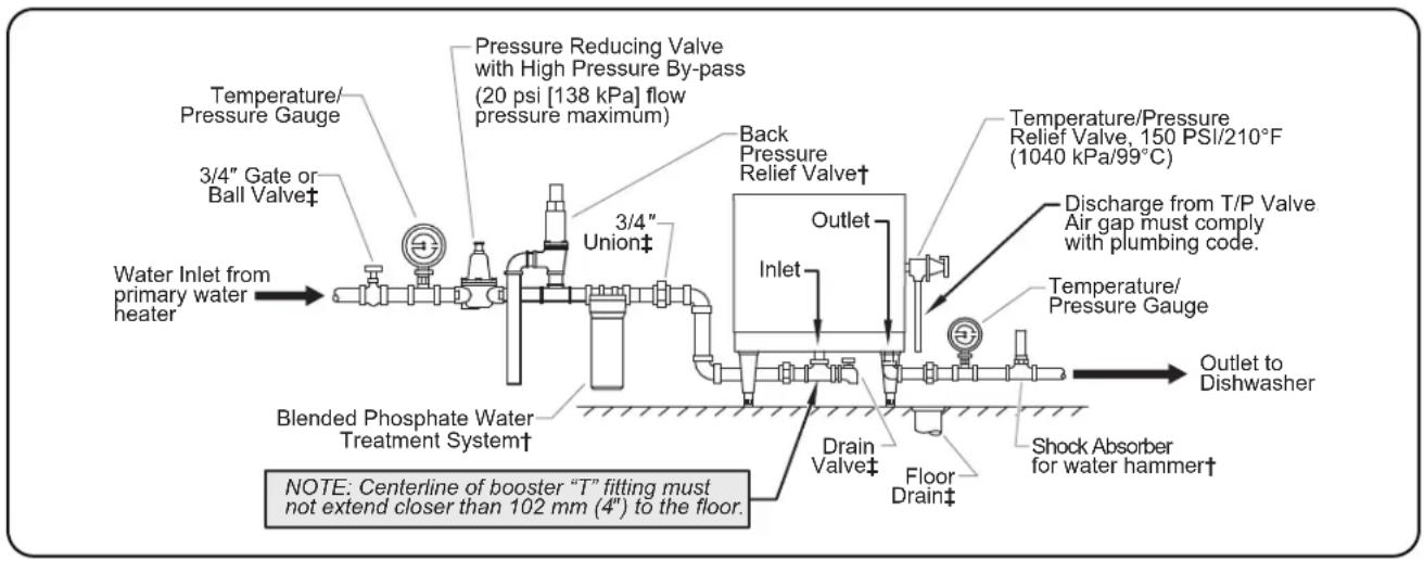
flowchart
graph LR
    A["Water Inlet from primary water heater"] --> B["Blended Phosphate Water Treatment System†"]
    B --> C["3/4" Gate or Ball Valve‡"]
    C --> D["Pressure Reducing Valve with High Pressure By-pass (20 psi [138 kPa"] flow pressure maximum)]
    D --> E["3/4" Union‡"]
    E --> F["Back Pressure Relief Valve†"]
    F --> G["Outlet"]
    G --> H["Inlet"]
    H --> I["Drain Valve‡"]
    I --> J["Floor Drain‡"]
    J --> K["Shock Absorber for water hammer†"]
    K --> L["Outlet to Dishwasher"]
    M["Temperature/Pressure Gauge"] --> N["3/4" Gate or Ball Valve‡"]
    O["Temperature/Pressure Relief Valve, 150 PSI/210°F (1040 kPa/99°C)"] --> P["Discharge from T/P Valve Air gap must comply with plumbing code."]
    P --> Q["Thermal/Pressure Gauge"]
Imperial "S" Series
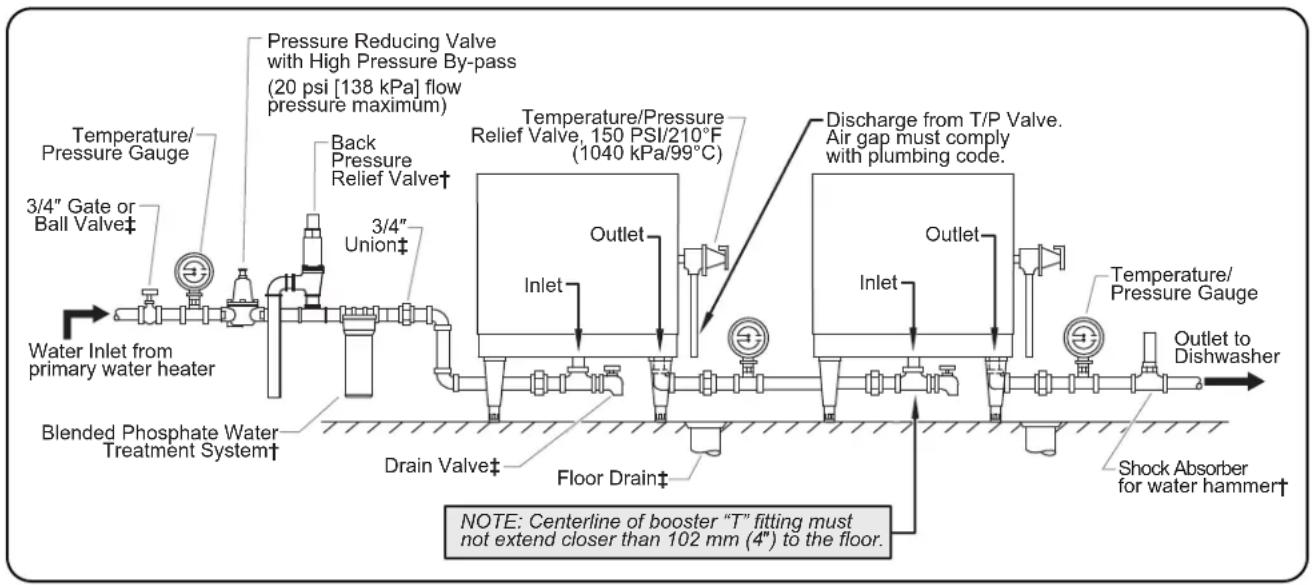
flowchart
graph LR
    A["Water Inlet from primary water heater"] --> B["Blended Phosphate Water Treatment System†"]
    B --> C["3/4" Gate or Ball Valve‡"]
    C --> D["3/4" Union‡"]
    D --> E["Back Pressure Relief Valve†"]
    E --> F["Pressure Reducing Valve with High Pressure By-pass (20 psi [138 kPa"] flow pressure maximum)]
    F --> G["Temperature/Pressure Gauge"]
    G --> H["Outlet"]
    H --> I["Inlet"]
    I --> J["Outlet"]
    J --> K["Discharge from T/P Valve. Air gap must comply with plumbing code."]
    K --> L["Outlet"]
    L --> M["Inlet"]
    M --> N["Outlet"]
    N --> O["Temperature/Pressure Gauge"]
    O --> P["Outlet to Dishwasher"]
    P --> Q["Shock Absorber for water hammer†"]
    Q --> R["Floor Drain‡"]
    R --> S["Drain Valve‡"]
    S --> T["Water Inlet from primary water heater"]
Two Imperial Models Connected in Series
† Not supplied, but is available as an option/accessory.
‡ Not supplied with booster heater.
WARNING
Valves, gauges, and unions must be installed per diagram to ensure proper operation, servicing, and warranty coverage.
Plumbing Connections
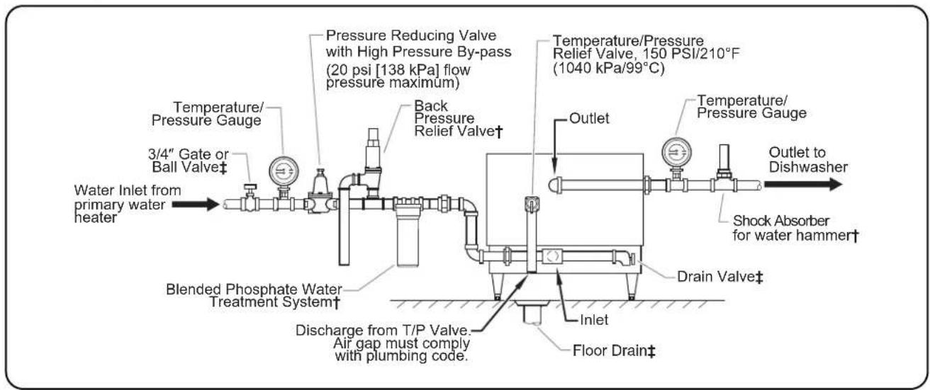
flowchart
graph LR
    A["Water Inlet from primary water heater"] --> B["3/4" Gate or Ball Valve‡"]
    B --> C["Temperature/Pressure Gauge"]
    C --> D["Pressure Reducing Valve with High Pressure By-pass (20 psi [138 kPa"] flow pressure maximum)]
    D --> E["Back Pressure Relief Valve†"]
    E --> F["Outlet"]
    F --> G["Temperature/Pressure Gauge"]
    G --> H["Outlet to Dishwasher"]
    H --> I["Shock Absorber for water hammer†"]
    I --> J["Drain Valve‡"]
    J --> K["Inlet"]
    K --> L["Discharge from T/P Valve. Air gap must comply with plumbing code."]
    L --> M["Floor Drain‡"]
Compact Series
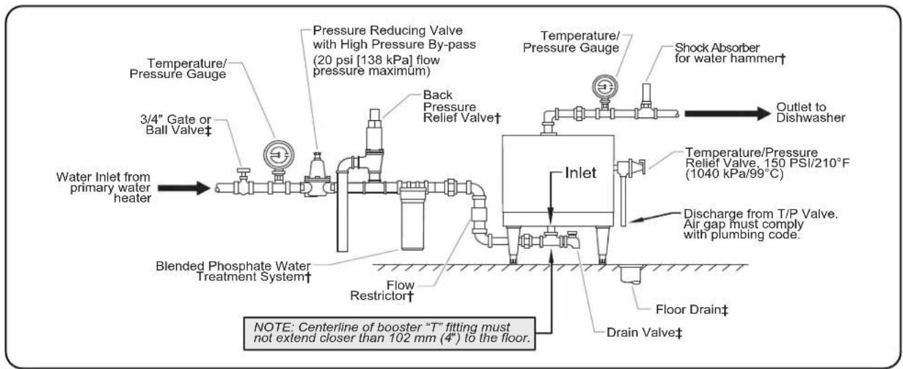
flowchart
graph LR
    A["Water Inlet from primary water heater"] --> B["Blended Phosphate Water Treatment System†"]
    B --> C["Flow Restrictor†"]
    C --> D["Inlet"]
    D --> E["Temperature/Pressure Gauge"]
    D --> F["Back Pressure Relief Valve†"]
    D --> G["Pressure Reducing Valve with High Pressure By-pass (20 psi [138 kPa"] flow pressure maximum)]
    D --> H["Shock Absorber for water hammer†"]
    D --> I["Discharge from T/P Valve. Air gap must comply with plumbing code."]
    D --> J["Floor Drain‡"]
    D --> K["Drain Valve‡"]
    D --> L["Outlet to Dishwasher"]
    D --> M["Note: Centerline of booster "T" fitting must not extend closer than 102 mm (4") to the floor."]
Mini-Compact Models
† Not supplied, but is available as an option/accessory.
‡ Not supplied with booster heater.
WARNING
Valves, gauges, and unions must be installed per diagram to ensure proper operation, servicing, and warranty coverage.
Outlet
- Flush the water supply line to remove any pipe compound and foreign matter.
- Connect the booster heater water outlet to the commercial dish machine sanitizing rinse pipe connection using a 3/4" union and piping.
NOTICE
DO NOT turn or adjust water outlet connection on Large Compact Series units (C-24 to C-57).
NOTE: Red mark on water outlet pipe for C-24 to C-57 series units must remain in the top most position.
NOTE: Be certain the connection is made to the final rinse and not to the wash tank.
- Install a temperature/pressure gauge in the outlet line. The temperature sensing element must be in the water stream and the gauge must be mounted upright.
- Water temperature at the outlet should be 185^ - 190^ (85^ - 88^) .
NOTE: Some dish machines require two booster heaters to be plumbed in series (not parallel) to meet the demand. To ensure proper operation, a 30^ F (-1°C) temperature differential must be maintained between the outlet of the first booster heater and the inlet of the second booster heater.
NOTE: Hatco recommends installing an optional shock absorber (P/N 03.04.057.00) in the outlet line as close as possible to the commercial dish machine solenoid rinse valve. The shock absorber softens the water hammer caused by automatic dish machine valves.
Plumbing Installation Inspection
- Close the drain valve and fill the booster heater with water.
- Check all pipe connections for leaks.
- Make sure the temperature/pressure relief valve discharge is not blocked.
- Vent air from the tank before operating by opening the temperature/pressure relief valve.
CAUTION
DO NOT turn on power to the booster heater until tank has been filled with water and all air has been vented through the dish machine rinse nozzle. The heating elements will burn out in seconds if operated when they are not immersed in water.
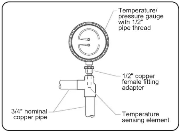
Recommended Temperature/Pressure Gauge Installation
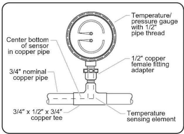
Alternate Temperature/Pressure Gauge Installation
WARNING
Hatco has always endorsed the use of safety equipment when using a booster water heater or storage-type water heater. Hatco booster heaters are shipped with a temperature/pressure relief valve at no extra charge. This valve must be installed into the marked opening provided in the tank. Valves supplied by Hatco are designed for high temperature commercial operation. Do not substitute Hatco supplied valves with valves designed for domestic operation.
It is essential to recognize that even though a water heater may be properly installed initially and approved, there always exists the possibility that unknowing individuals might alter or change the installation in a manner that would render it unsafe. Therefore, it is important that all safety programs provide some mechanism to assure that these installations are inspected periodically.
Electrical — All Sizes and Voltages
General
Hatco Electric Booster Water Heaters are available for operation on standard power systems. Check the specification label for the proper power supply.
All internal electrical connections have been made at the factory. See the "Circuit Breaker and Fused Disconnect Switch" chart in the SPECIFICATIONS section for supply wire size, fuse, breaker, and conduit recommendations. Consult local codes for verification and compliance.
WARNING
ELECTRIC SHOCK HAZARD:
- Unit must be installed by qualified, trained installers. Installation must conform to all local electrical and plumbing codes. Installation by unqualified personnel will void the unit warranty and may lead to electric shock or burn, as well as damage to unit and/or its surroundings. Check with local plumbing and electrical inspectors for proper procedures and codes.
- Turn OFF power at fused disconnect switch/circuit breaker and allow unit to cool before performing any cleaning, adjustments, or maintenance.
- Consult a licensed electrical contractor for proper electrical installation conforming to local electrical codes and the National Electrical Code (N.E.C.).
NOTICE
Units are voltage-specific. Refer to specification label for electrical requirements before beginning installation. Connecting unit to incorrect power supply will void product warranty and may damage unit.
Electrical Connections
- Remove the front jacket cover screws, pull the cover forward and remove the cover.
NOTE: On Imperial models, there is a hinged access panel under the front jacket cover. Remove the bottom screw and lift the panel up to expose the fuse blocks.
- On Mini-Compact models, remove front cover screws. Ease cover forward and upward.
-
On Compact models, the control box is under the front hinged jacket cover.
-
Locate the heater terminal or fuse block(s) inside the unit.
NOTE: See "Circuit Breaker and Fused Disconnect Switch" chart in the SPECIFICATIONS section for proper connections and wire size.
NOTE: Only 6, 7, and 9 kW models, in 208 or 240 volt, can be converted to single or three phase in the field. Refer to the wiring diagram for proper wiring connections at the terminal block.
- Bring power leads from a properly sized disconnect switch or circuit breaker through the knockout provided on the unit. Connect leads to the terminal or fuse block(s). USE COPPER WIRE ONLY. TIGHTEN CONNECTIONS PROPERLY TO A MINIMUM OF 40 INCH POUNDS.
NOTE: Due to the rigors of transportation all connections should be checked for tightness before heater is put into operation.
- Properly connect an equipment grounding connector to the grounding lug (located near the supply terminals).
CAUTION
DO NOT turn on power to the booster heater until tank has been filled with water and all air has been vented through the dish machine rinse nozzles. Heating elements will burn out in seconds if operated when not immersed in water.
- Replace and secure cover(s).
Imperial Series
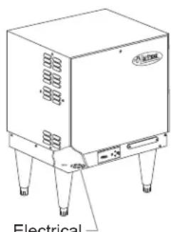
Electrical Knockout
Compact Series
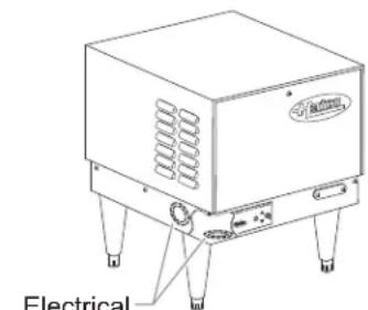
natural_image
Line drawing of a portable electrical device with ventilation slots and mounting legs (no text or symbols)Electrical Knockouts
Mini-Compact Series
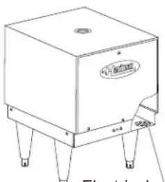
Electrical Knockout
Electrical Knockout Locations
General
Use the following procedures to operate Hatco Electric Booster Water Heaters.
CAUTION
BURN HAZARD: Water in unit is very hot. Wear protective gloves and proper attire when operating to avoid injury.
Startup
- Close the drain valve.
- Open the shutoff valve to the primary water supply line. The water temperature at inlet should be 110^ to 140^ F ( 43^ to 60^ C) and should not exceed 160^ F ( 71^ C).
NOTE: Minimum temperature differential between inlet and outlet should never be less than 30^ F ( -1^ C).
- Vent all the air from the tank through the dish machine rinse nozzles and the temperature/pressure relief valve when the tank is filled with water.
CAUTION
DO NOT turn on power to the booster heater until tank has been filled with water and all air has been vented through the dish machine rinse nozzles. Heating elements will burn out in seconds if operated when not immersed in water.
- Check all plumbing connections for leaks.
- Check the temperature/pressure relief valve discharge opening to be sure it is not blocked and no scale or other foreign matter has reduced the size of the opening.
- Turn on the booster water heater.
- For Imperial and Compact models, move the Power ON/OFF (I/O) switch on the control panel to the ON (I) position.
- For Mini-Compact models, turn on power at the fused disconnect switch/circuit breaker.
NOTE: Mini-Compact models can be configured with an optional Power ON/OFF (I/O) switch.
- When the booster water heater has had sufficient heating time, operate the rinse cycle and check the water temperature and pressure readings on the gauges.
- Water temperature at the booster outlet should be 185°–190°F (85°–88°C) and flow pressure should be 20 psi (138 kPa) maximum.
NOTE: Outlet water temperatures can be adjusted for Low-Temperature Dish Machine applications. See the MAINTENANCE section for thermostat adjustment procedure.
WARNING
Units are equipped with a high temperature limit safety switch that will shut off the power if the unit overheats. Contact an Authorized Hatco Service Agent if the high temperature limit safety switch cannot be reset or continues to trip.
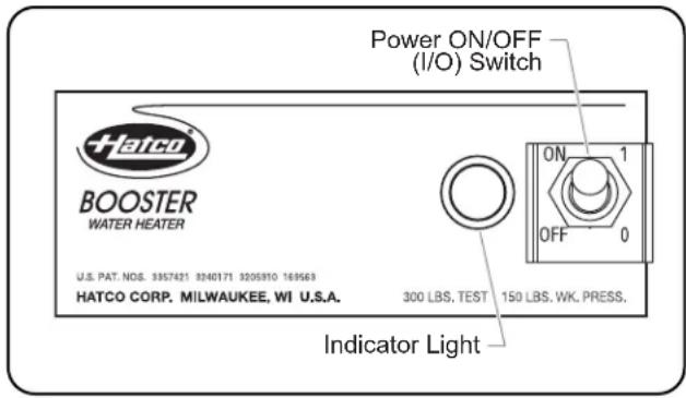
Control Panel (Imperial and Compact models shown)
Shutdown
Under normal and regular operation, Hatco recommends that the unit be turned on at all times.
If the booster heater will not be used for an extended period of time or will be exposed to freezing conditions, it should be drained to prevent damage to the unit.
- Move the Power ON/OFF (I/O) switch to the OFF (O) position, and turn off power at the fused disconnect switch/circuit breaker.
- Close the shutoff valve to the primary water supply line.
- Open the drain valve and drain the water from the booster heater tank.
NOTICE
Always drain booster heater with power to the unit off or element burnout could occur.
General
Electric Booster Water Heaters are designed for maximum durability and performance with minimum maintenance.
WARNING
ELECTRIC SHOCK HAZARD:
- Turn OFF power at fused disconnect switch/circuit breaker and allow unit to cool before performing any cleaning, adjustments, or maintenance.
- This unit must be serviced by qualified personnel only. Service by unqualified personnel may lead to electric shock or burn.
- Use only Genuine Hatco Replacement Parts when service is required. Failure to use Genuine Hatco Replacement Parts will void all warranties and may subject operators of the equipment to hazardous electrical voltage, resulting in electrical shock or burn. Genuine Hatco Replacement Parts are specified to operate safely in the environments in which they are used. Some aftermarket or generic replacement parts do not have the characteristics that will allow them to operate safely in Hatco equipment.
This unit has no "user-serviceable" parts. If service is required on this unit, contact an Authorized Hatco Service Agent or contact the Hatco Service Department at 800-558-0607 or 414-671-6350; fax 800-690-2966; or International fax 414-671-3976.
Thermostat Adjustment
The thermostat is factory calibrated at 185^-190^ ( 85^-88^ ). If adjustment or recalibration is required due to the rigors of transportation, use the following procedure.
NOTE: Low temperature dish machines require the thermostat(s) to be adjusted to 140^-150^ ( 60^-66^ ).
- Move the Power ON/OFF (I/O) switch to the OFF (O) position and unplug the unit from the power source.
- Remove the access cover.
-
Adjust the temperature setpoint to the desired temperature.
-
To lower the temperature setpoint, turn the outer screw counterclockwise.
- To raise the temperature setpoint, turn the outer screw clockwise.
NOTE: 1/6 turn of the outer screw equals 12^ F ( 6.7^ C).
NOTE: If recalibration is necessary, with the outer screw at high stop, turn the inner screw clockwise to raise the set point.
NOTE: 1/6 turn of the inner screw equals 8^ F ( 4.4^ C).
High Temperature Limit Safety Switch
All Hatco Electric Booster Water Heaters are equipped with a manually reset high temperature limit safety switch. If the temperature of the water in the heater exceeds 210^ F ( 99^ C) the safety switch will shut off the power. The switch must be manually reset.
If the high temperature limit safety switch needs to be reset use the following procedure:
- Move the Power ON/OFF (I/O) switch to the OFF (O) position and unplug the unit from the power source.
- Remove the access cover.
- Push the red reset button.
- If tripping repeats, call an Authorized Service Agent. Do NOT attempt to adjust the High Temperature Limit Safety Switch.
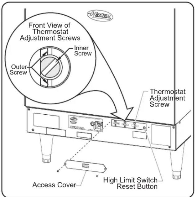
Thermostat Adjustment and High Temperature Limit Safety Switch (Imperial "S" Model Shown)
Stainless Steel Adjustable Legs
Stainless steel adjustable legs (P/N 05.30.070.00) are available as accessories for all models.
Use the following procedure to install legs:
- Carefully place unit on its side.
NOTICE
Do not lay unit on the side with the control panel. Damage to the unit could occur.
- Thread the adjustable legs into the existing leg holes on the bottom of the unit.
- After all legs are secure, return the unit to the upright position.
NOTE: If unit is not level, use an adjustable wrench to adjust the foot of each leg until unit is level. Each leg is adjustable from 6" (152 mm) to 7" (178 mm).
Stainless Steel Adjustable Legs
Floor Mounting Legs
Stainless steel adjustable legs with deck mounting flanges secure the booster heater to the floor are available options for Compact and Imperial models only.
Mounting Slide Brackets
A set of optional mounting slide brackets is available for Compact models only. (P/N R04.20.030.00)
Plumbing Accessories
A shock absorber, a brass pressure reducing valve, and a back pressure relief valve are available as accessories.
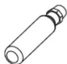
Shock Absorber P/N 03.40.057.00)
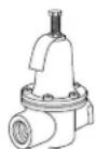
Brass Pressure Reducing Valve (P/N 03.02.015.00)
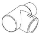
Back Pressure Relief Valve* (P/N 03.02.039.00)
*Not available for Mini-Compact models.
Plumbing Accessories
Blended Phosphate Water Treatment System
The optional Blended Phosphate Water Treatment System (P/N 03.05.061.00) dispenses a small amount of polyphosphate into the water. The polyphosphate prevents the buildup of mineral molecules.
The optional blended phosphate water treatment system is installed with unions on the incoming 3/4" water supply line after the pressure reducing valve and before the booster heater.
Replacing a Phosphate Cartridge (P/N 03.05.061A.00)
Cartridges supplied have a usage rating of 100,000 gallons (378,541 liters) of water. To ensure proper operation, the cartridges must be replaced when the compound is near the bottom of the cartridge.
Use the following procedure for replacement:
- Move the ON/OFF (I/O) switch to the OFF (O) position.
- Shut off water supply and open the drain valve to remove water in piping.
- Loosen the canister using the attached wrench.
- Remove canister and discard depleted cartridge.
- Using a clean damp cloth, wipe the interior of the canister clean.
NOTE: Make sure the O-ring seal is placed properly in the canister.
- Reverse the above procedure to reinstall.
NOTE: Product failure caused by liming or sediment buildup is not covered under warranty.
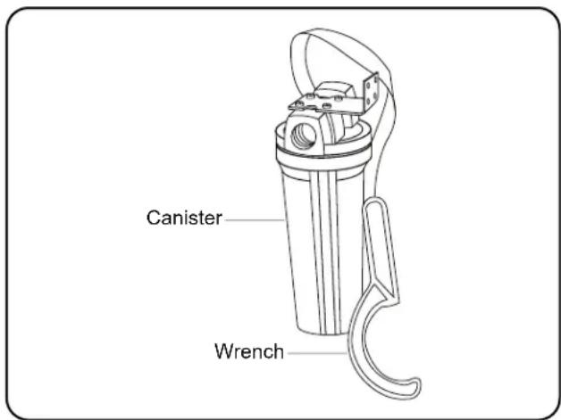
Blended Phosphate Water Treatment System
Stainless Body and Base
An optional stainless body and base is available for all models.
Security Package
A security package is a factory-installed option for Compact and Imperial models only. A security package contains Toriscrews and a control cover.
IMPORTANT! Read Before Using the Troubleshooting Guide
Many times when a booster heater does not appear to be functioning properly, the fault is not with the booster heater itself but with factors outside the heater.
WARNING
ELECTRIC SHOCK HAZARD:
- Turn OFF power at fused disconnect switch/circuit breaker and allow unit to cool before performing any cleaning, adjustments, or maintenance.
- This unit must be serviced by qualified personnel only. Service by unqualified personnel may lead to electric shock or burn.
Before proceeding with the "Troubleshooting Guide" to diagnose an issue, check ALL of the following outside factors.
Water Temperature
- Check the temperature of the water feeding into the booster tank. It must be 110° to 140°F (43° to 60°C), depending on the heating capability of the unit. The inlet water supply must be of sufficient quantity to hold its temperature throughout the dishwashing operation.
- If the wash tank of the dish machine is filled through the booster heater, this will use up all of the 180°F (82°C) water in storage. Sufficient time must be allowed to reheat the water in storage before starting the dish machine.
- Primary water heater temperature should not exceed 160°F (71°C).
Water Pressure
- Water pressure at the inlet to the booster heater must be adequate for proper operation of the rinse cycle of the dish machine, not to exceed 20 psi (138 kPa). Check with dish machine manufacture for specific details.
- If incoming water exceeds 20 psi (138 kPa), a pressure reducing valve must be installed.
Electrical Connections
- Booster heater voltage must be correct for voltage available. Check the specification label on the booster heater for full information.
- The breakers or fuses MUST be properly sized.
Plumbing Connections
- The temperature/pressure relief valve must be properly installed and be supplied by Hatco.
- A check valve should not be installed ahead of the booster.
NOTE: If a check valve is installed and cannot be removed, install a back pressure relief valve (P/N 03.02.039.00) set at 125 psi (862 kPa) on the incoming line between the pressure reducing valve and the inlet to the booster heater. Discharge must be to open site drain.
If the unit does not function properly after performing these checks, continue to the "Troubleshooting Guide" in this section.
WARNING
This unit must be serviced by qualified personnel only. Service by unqualified personnel may lead to electric shock or burn.
WARNING
ELECTRIC SHOCK HAZARD: Turn OFF power at fused disconnect switch/circuit breaker and allow unit to cool before performing any cleaning, adjustments, or maintenance.
| Symptom Probable | Cause Corrective Action | |
| Water reaches 180°F (82°C) but does not last through the entire dish machine operation. | Low incoming water temperature. Incoming | water temperature must be adequate for booster size. Increase incoming water temperature. |
| Incoming water temperature drops. Primary | water supply is not adequate to provide correct temperature in sufficient quantities. Increase supply of primary hot water. | |
| Flow pressure is too high. Higher pressure uses an excessive quantity of hot water. Adjust flow pressure to 20 psi (138 kPa). | ||
| Booster heater may be undersized. | Booster heater must be properly sized for incoming water temperature and rinse requirements of the dish machine. | |
| Incorrect voltage. Check voltage on heater serial plate and make sure supplied voltage matches. A 240V booster heater operating on 208V reduces wattage to 76% efficiency. | ||
WARNING
This unit must be serviced by qualified personnel only. Service by unqualified personnel may lead to electric shock or burn.
WARNING
ELECTRIC SHOCK HAZARD: Turn OFF power at fused disconnect switch/circuit breaker and allow unit to cool before performing any cleaning, adjustments, or maintenance.
| Symptom Probable | Cause Corrective Action | |
| The booster heater does not heat at all or only delivers water at 120°-150°F (49°-66°C). | Unit may have been energized without water (dry fired) causing the element(s) to burn out quickly. | Replace the element(s). |
| Fuses may be blown or circuit breaker tripped. | Check for proper fuse sizing. Replace fuses. Check/reset circuit breaker. | |
| Over-current fuses may be blown. Check for | shorted elements, bad fuse block or short in wiring. | |
| Temperature setting out of calibration or inoperable. | Temperature setting should be maximum of 190°F (88°C). | |
| Contactors do not pull in. Test for voltage at | coils. If coils are open or shorted, replace contactors. | |
| High limit switch may be tripped or defective | Reset switch, refer to “High Temperature Limit Safety Switch” in the MAINTENANCE section. If switch continues to trip or cannot be reset contact an Authorized Service Agent. | |
| Transformer not working properly. | Check secondary voltage, it should be the same as the control circuit voltage. If not, replace the transformer. | |
| Low water cutoff inoperable, contacts do not close. | Remove probe wire and touch it to the tank. If contacts close, probe is fouled and must be cleaned or replaced.Relay on circuit board maybe defective.Jumper terminals 6 and 7. If unit energizes, circuit board is defective and should be replaced. | |
| Water at dish machine is not at the proper temperature. | Gauge(s) not working properly. | Check temperature of water with a thermometer to be certain gauges are working correctly. If not, replace gauge(s). |
| Thermostat set too low. | Adjust or recalibrate, refer to “Thermostat Adjustment” in the MAINTENANCE section. If thermostat will not recalibrate properly, replace it. | |
| Booster heater has more than five (5) linear feet (1524 mm) of water pipe to the dish machine, causing the water to cool off inside the pipe. | If located farther than five (5) linear feet (1524 mm), pipes should be wrapped in insulation, and/or a recirculating system installed. | |
| Relief valve dribbles. No pressure | reducing valve installed or incorrect valve installed causing pressure build-up inside booster tank. | A pressure reducing valve with high pressure bypass must be installed in the incoming water line to allow water to expand back into the feed line. |
| Bypass in pressure reducing valve may be blocked. | Clean bypass or replace with new valve with built in bypass. | |
| Check valve or anti-siphon valve installed in the feed line. | Remove check valve or anti-siphon valve to allow for water expansion or install a back pressure relief valve (P/N 03.02.039.00) on the incoming water line. | |
| Relief valve opens. Unit is overheating. | Thermostat may be set too high or is sticking. Recalibrate or replace the thermostat. | |
| Contactor may be sticking in closed position not allowing unit to cycle off. | Replace contactor(s). | |
| High temperature limit safety switch trips. | Temperature limit safety switch is defective. | If booster heater is not overheating, replace High Limit Safety Switch. |
| Thermostat set too high. | Adjust or recalibrate, refer to “Thermostat Adjustment” in the MAINTENANCE section. | |
| Incoming water temperature too high causing nuisance tripping of high temperature limit switch. | Incoming water temperature should not be higher than 160°F (71°C). | |
| Chattering contactor or low water cutoff circuit board | Loose connections or wire connection has insulation under crimp. | Tighten all connections and check crimps |
| Low voltage. | Check control circuit voltage or secondary voltage with transformer. | |
| Probe may be fouled. | Bypass probe by removing wire from low water cutoff probe and grounding to tank. Clean or replace probe if chattering stops. | |
| Contactor(s) may be bad. | Test contactor coils and replace if needed. | |
| Heating element(s) burn out. | Tank inadvertently drained leaving element(s) in a dry condition. | Replace element(s), and make sure tank is full of water at all times. Check low water cut-off system for proper operation. |
| Lime buildup in tank causing element(s) to split and burn out. | Replace element(s), and clean or delime tanks periodically. A water softener or blended phosphate treatment system may be required. | |
Troubleshooting Questions?
If you continue to have problems resolving an issue, please contact the nearest Authorized Hatco Service Agency or Hatco for assistance. To locate the nearest Service Agency, log onto the Hatco website at www.hatcocorp.com and click on Find Service Agent, or contact the Hatco Parts and Service Team at:
Telephone: 800-558-0607 or 414-671-6350
e-mail: partsandservice@hatcocorp.com
Fax: 800-690-2966 or 414-671-3976
1. PRODUCT WARRANTY
Hatco warrants the products that it manufactures (the "Products") to be free from defects in materials and workmanship, under normal use and service, for a period of one (1) year from the date of purchase when installed and maintained in accordance with Hatco's written instructions or 18 months from the date of shipment from Hatco. Buyer must establish the Product's purchase date by registering the Product with Hatco or by other means satisfactory to Hatco in its sole discretion.
Hatco warrants the following Product components to be free from defects in materials and workmanship from the date of purchase (subject to the foregoing conditions) for the period(s) of time and on the conditions listed below:
a) One (1) Year Parts and Labor PLUS One (1) Additional Year Parts-Only Warranty:
Conveyor Toaster Elements (metal sheathed)
Drawer Warmer Elements (metal sheathed)
Drawer Warmer Drawer Rollers and Slides
Strip Heater Elements (metal sheathed)
Display Warmer Elements (metal sheathed air heating)
Holding Cabinet Elements (metal sheathed air heating)
Heated Well Elements — HW and HWB Series (metal sheathed)
b) One (1) Year Parts and Labor PLUS Four (4) Years Parts-Only Warranty:
3CS and FR Tanks
c) One (1) Year Parts and Labor PLUS Nine (9) Years Parts-Only Warranty on:
Electric Booster Heater Tanks
Gas Booster Heater Tanks
d) Ninety (90) Day Parts-Only Warranty:
Replacement Parts
THE FOREGOING WARRANTIES ARE EXCLUSIVE AND IN LIEU OF ANY OTHER WARRANTY, EXPRESSED OR IMPLIED, INCLUDING BUT NOT LIMITED TO ANY IMPLIED WARRANTY OF MERCHANTABILITY OR FITNESS FOR A PARTICULAR PURPOSE OR PATENT OR OTHER INTELLECTUAL PROPERTY RIGHT INFRINGEMENT. Without limiting the generality of the foregoing, SUCH WARRANTIES DO NOT COVER: Coated incandescent light bulbs, fluorescent lights, heat lamp bulbs, coated halogen light bulbs, halogen heat lamp bulbs, xenon light bulbs, LED light tubes, glass components, and fuses; Product failure in booster tank, fin tube heat exchanger, or other water heating equipment caused by liming, sediment buildup, chemical attack, or freezing; or Product misuse, tampering or misapplication, improper installation, or application of improper voltage.
2. LIMITATION OF REMEDIES AND DAMAGES
Hatco's liability and Buyer's exclusive remedy hereunder will be limited solely, at Hatco's option, to repair or replacement using new or refurbished parts or Product by Hatco or a Hatco-authorized service agency (other than where Buyer is located outside of the United States, Canada, United Kingdom, or Australia, in which case Hatco's liability and Buyer's exclusive remedy hereunder will be limited solely to replacement of part under warranty) with respect to any claim made within the applicable warranty period referred to above. Hatco reserves the right to accept or reject any such claim in whole or in part. In the context of this Limited Warranty, "refurbished" means a part or Product that has been returned to its original specifications by Hatco or a Hatco-authorized service agency. Hatco will not accept the return of any Product without prior written approval from Hatco, and all such approved returns shall be made at Buyer's sole expense. HATCO WILL NOT BE LIABLE, UNDER ANY CIRCUMSTANCES, FOR CONSEQUENTIAL OR INCIDENTAL DAMAGES, INCLUDING BUT NOT LIMITED TO LABOR COSTS OR LOST PROFITS RESULTING FROM THE USE OF OR INABILITY TO USE THE PRODUCTS OR FROM THE PRODUCTS BEING INCORPORATED IN OR BECOMING A COMPONENT OF ANY OTHER PRODUCT OR GOODS.
natural_image
Line drawing of a rectangular industrial machine with cooling unit and mounting legs (no text or symbols)Modèle Imperial
natural_image
Line drawing of a portable industrial device with ventilation slots and mounting feet (no text or symbols)Modèle Compact
natural_image
Line drawing of a square electronic device with four legs and a label on the front face (no readable text or symbols beyond branding)Modèle Mini-Compact
natural_image
Pure technical line drawing of a mechanical component with no text or symbolsAVIS
Support de suspension
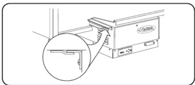
natural_image
Technical line drawing of a pressure gauge or pressure relief device (no text or symbols)natural_image
Line drawing of a portable electronic device with ventilation slots and four legs (no text or symbols)natural_image
Line drawing of a rectangular electronic device with three legs and a central label (no readable text or symbols)BURN HAZARD: Water in unit is very hot. Wear protective gloves and proper attire when operating to avoid injury.
Allumage
1. GARANTIE DU PRODUIT
Industrial Electric Commercial Parts & Service, Inc. Huntington Beach 714-379-7100
Chapman Appl. Service San Diego 619-298-7106
P & D Appliance Commercial Parts & Service, Inc. S. San Francisco 650-635-1900
COLORADO
Hawkins Commercial Appliance Englewood 303-781-5548
FLORIDA
Whaley Foodservice Repair Jacksonville 904-725-7800
3Wire Nass Service Co., Inc. Orlando 407-425-2681
B.G.S.I. Pompano Beach 954-971-0456
Comm. Appliance Service Tampa 813-663-0313
GEORGIA
TWC Services Mableton 770-438-9797
Heritage Service Group Norcross 866-388-9837 Southeastern Rest. Svc. Norcross 770-446-6177
HAWAII
Burney's Comm. Service, Inc. Honolulu 808-848-1466 Food Equip Parts & Service Honolulu 808-847-4871
ILLINOIS
Parts Town Lombard 708-865-7278 Eichenauer Elec. Service Decatur 217-429-4229 Midwest Elec. Appl. Service Elmhurst 630-279-8000 Cone's Repair Service Moline 309-797-5323
INDIANA
GCS Service Indianapolis 317-545-9655
IOWA
Electric Motor Service Co. Davenport 319-323-1823
Goodwin Tucker Group Des Moines 515-262-9308
KENTUCKY
Service Solutions Group Lexington 859-254-8854 Service Solutions Group Louisville 502-451-5411
LOUISIANA
Chandlers Parts & Service Baton Rouge 225-272-6620
MARYLAND
Electric Motor Service Baltimore 410-467-8080 GCS Service Silver Spring 301-585-7550
MASSACHUSETTS
Ace Service Co., Inc. Needham 781-449-4220
MICHIGAN
Bildons Appliance Service Detroit 248-478-3320
Commercial Kitchen Service Bay City 517-893-4561 Midwest Food Equip. Service Grandville 616-261-2000
MINNESOTA
GCS Service Plymouth 800-345-4221
MISSOURI
General Parts Kansas City 816-421-5400 Commercial Kitchen Services St. Louis 314-890-0700 Kaemmerlen Parts & Service St. Louis 314-535-2222
NEBRASKA
Anderson Electric Omaha 402-341-1414
NEVADA
Burney's Commercial Las Vegas 702-736-0006 Hi. Tech Commercial Service N. Las Vegas 702-649-4616
NEW JERSEY
Jay Hill Repair Fairfield 973-575-9145 Service Plus Flanders 973-691-6300
NEW YORK
Acme American Repairs, Inc. Brooklyn 718-456-6544
Alpro Service Co. Brooklyn 718-386-2515
Appliance Installation Buffalo 716-884-7425
Duffy's Equipment Services, Inc. Buffalo 800-836-1014
3Wire Northern Plattsburgh 800-634-5005
Duffy's Equipment Services, Inc. Sauquoit 800-836-1014 J.B. Brady, Inc. Syracuse 315-422-9271
NORTH CAROLINA
Authorized Appliance Charlotte 704-377-4501
OHIO
Akron/Canton Comm. Svc. Inc. Akron 330-753-6635
Service Solutions Group Cincinnati 513-772-6600
Commercial Parts and Service Columbus 614-221-0057
Electrical Appl. Repair Service Brooklyn Heights 216-459-8700
E. A. Wichman Co. Toledo 419-385-9121
OKLAHOMA
Hagar Rest. Service, Inc. Oklahoma City 405-235-2184
Krueger, Inc. Oklahoma City 405-528-8883
OREGON
Ron's Service, Inc. Portland 503-624-0890
PENNSYLVANIA
Elmer Schultz Services Philadelphia 215-627-5401
FAST Comm. Appl. Service Philadelphia 215-288-4800
Appliance Installation & Service Pittsburgh 412-809-0244
K & D Service Co. Harrisburg 717-236-9039 Electric Repair Co. Reading 610-376-5444
RHODE ISLAND
Marshall Electric Co. Providence 401-331-1163
SOUTH CAROLINA
Whaley Foodservice Repair W. Columbia 803-791-4420
TENNESSEE
Camp Electric Memphis 901-527-7543
TEXAS
GCS Service Fort Worth 800-433-1804
Armstrong Repair Service Houston 713-666-7100
Cooking Equipment Specialist Mesquite 888-866-9276
Refrigerated Specialist, Inc. Mesquite 888-866-9276
Commercial Kitchen Repair Co. San Antonio 210-735-2811
UTAH
La Monica's Rest. Equip. Service Murray 801-263-3221
VIRGINIA
Daubers Norfolk 757-855-4097
Daubers
Springfield 703-866-3600
WASHINGTON
3 Wire Restaurant Appliance Seattle 800-207-3146
WISCONSIN
A.S.C., Inc. Madison 608-246-3160 A.S.C., Inc. Milwaukee 414-543-6460
CANADA
ALBERTA
Key Food Equipment Service Edmonton 780-438-1690
BRITISH COLUMBIA
Key Food Equipment Service Vancouver 604-433-4484
Key Food Equipment Service Victoria 250-920-4888
MANITOBA
Air Rite, Inc. Winnipeg 204-895-2300
NEW BRUNSWICK
EMR Services, Ltd. Moncton 506-855-4228
ONTARIO
R.G. Henderson Ltd. Toronto 416-422-5580
Choquette - CKS, Inc. Ottawa 613-739-8458
QUÉBEC
Choquette - CKS, Inc. Montreal 514-722-2000
Choquette - CKS, Inc. Québec City 418-681-3944
UNITED KINGDOM
Marren Group Northants +44(0)1933 665313
HATCO CORPORATION
P.O. Box 340500
Milwaukee, WI 53234-0500 U.S.A.
800-558-0607 414-671-6350
Parts and Service Fax 800-690-2966
International Fax 414-671-3976
partsandservice@hatcocorp.com
www.hatcocorp.com
Register your unit online!
See IMPORTANT OWNER INFORMATION section for details.
- WARNING
- ADVERTENCIA
- IMPORTANT OWNER INFORMATION
- Register your unit!
- INTRODUCTION
- CAUTION
- NOTICE
- ELECTRIC SHOCK HAZARD:
- BURN HAZARD:
- All Models
- Imperial Models "S" Series
- Compact Models "C" Series
- Mini-Compact Models "MC" Series
- General
- Plumbing Installation
- Inlet
- Outlet
- DO NOT turn or adjust water outlet connection on Large Compact Series units (C-24 to C-57).
- Plumbing Installation Inspection
- Electrical — All Sizes and Voltages
- Electrical Connections
- Startup
- Shutdown
- Thermostat Adjustment
- High Temperature Limit Safety Switch
- Stainless Steel Adjustable Legs
- Do not lay unit on the side with the control panel. Damage to the unit could occur.
- Floor Mounting Legs
- Mounting Slide Brackets
- Plumbing Accessories
- Blended Phosphate Water Treatment System
- Replacing a Phosphate Cartridge (P/N 03.05.061A.00)
- Stainless Body and Base
- Security Package
- IMPORTANT! Read Before Using the Troubleshooting Guide
- Water Temperature
- Water Pressure
- Plumbing Connections
- Troubleshooting Questions?
- PRODUCT WARRANTY
- LIMITATION OF REMEDIES AND DAMAGES
- AVIS
- Allumage
- GARANTIE DU PRODUIT
- COLORADO
- FLORIDA
- GEORGIA
- HAWAII
- ILLINOIS
- INDIANA
- IOWA
- KENTUCKY
- LOUISIANA
- MARYLAND
- MASSACHUSETTS
- MICHIGAN
- MINNESOTA
- MISSOURI
- NEBRASKA
- NEVADA
- NEW JERSEY
- NEW YORK
- NORTH CAROLINA
- OHIO
- OKLAHOMA
- OREGON
- PENNSYLVANIA
- RHODE ISLAND
- SOUTH CAROLINA
- TENNESSEE
- TEXAS
- UTAH
- VIRGINIA
- WASHINGTON
- WISCONSIN
- CANADA
- ALBERTA
- BRITISH COLUMBIA
- MANITOBA
- NEW BRUNSWICK
- ONTARIO
- QUÉBEC
- UNITED KINGDOM
- Register your unit online!
Brand : Hatco
Model : C12
Category : Heating