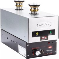
FR4B - Heating Hatco - Free user manual and instructions
Find the device manual for free FR4B Hatco in PDF.


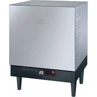
| Product Type | Bain-marie Warmer / Food Holding Cabinet |
| Brand | Hatco |
| Model | FR4B |
| Intended Use | Professional (catering, institutional kitchens) |
| Power Supply | Balanced three-phase, 208-240 V, 4.5 kW |
| Rated Current | 12.5 A (at 208 V) / 10.8 A (at 240 V) |
| Dimensions (W x D x H) | 435 x 216 x 117 mm (without container) |
| Net Weight | 14 kg |
| Material | Stainless steel (front) and powder-coated structure |
| Heating Reservoir Capacity | Approx. 2.4 to 4.3 liters (2.5-4.5 quarts) |
| Water Temperature Range | 60 to 88 °C (adjustable) |
| Maximum Water Temperature | 88 °C (do not exceed) |
| Filtration System | Double reservoir: settling tank and heating chamber |
| Safety Devices | High-limit thermostat (ECO) and low-water cutoff (LWCO) |
| Installation Type | Under a pan or container (drop-in model) |
| Connections | Water inlet and outlet 51 mm (2"), drains 19 mm (3/4") |
| Cleaning | Daily: rinse with clean water; regular descaling with white vinegar |
| Warranty | 1 year parts and labor + 4 additional years on the tank (parts only) |
| Standards | NSF construction certification (standard 4) |
| Available Accessories | Flushing hose kit, temperature monitor, indicator light, safety option |
Frequently Asked Questions - FR4B Hatco
User questions about FR4B Hatco
0 question about this device. Answer the ones you know or ask your own.
Ask a new question about this device
Download the instructions for your Heating in PDF format for free! Find your manual FR4B - Hatco and take your electronic device back in hand. On this page are published all the documents necessary for the use of your device. FR4B by Hatco.
USER MANUAL FR4B Hatco
Register Online! (see page 2)
natural_image
Line drawing of a laboratory instrument with two circular components and a control panel (no text or symbols)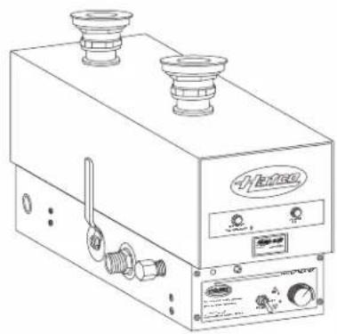
natural_image
Line drawing of a portable electronic device with two top ports and control panel (no text or symbols)WARNING
Do not operate this equipment unless you have read and understood the contents of this manual! Failure to follow the instructions contained in this manual may result in serious injury or death. This manual contains important safety information concerning the maintenance, use, and operation of this product. If you're unable to understand the contents of this manual, please bring it to the attention of your supervisor. Keep this manual in a safe location for future reference.
English = p 2
ADVERTENCIA
Important Owner Information....2
Introduction......2
Important Safety Information....3
NSF Criteria....4
Model Designations 4
Model Description 5
Specifications ....5
Plug Configurations 5
Electrical Rating Chart—3CS Models 6
Electrical Rating Chart—FR Models....8
Electrical Rating Chart—FRC Models 9
Dimensions....10
Installation....11
General....11
Sizing Information....11
Installing 3CS and FR Models....11
Installing FRC Models 13
Electrical Information....13
Operation....14
General 14
Maintenance....15
General....15
Daily Cleaning 15
Remove Lime and Mineral Deposits ....16
Draining Heater for Service Protection....16
Resetting the Energy Cut-Off Switch (ECO)....16
Troubleshooting Guide....16
Options and Accessories 17
Limited Warranty 18
Authorized Parts Distributors ....Back Cover
IMPORTANT OWNER INFORMATION
Record the model number, serial number (located on the lower right side on the front of the unit), voltage and purchase date of your Water Heater in the spaces below. Please have this information available when calling Hatco for service assistance.
Model No. ____
Serial No.
Voltage
Date of Purchase
Register your unit!
Completing online warranty registration will prevent delay in obtaining warranty coverage. Access the Hatco website at www.hatcocorp.com, select the Parts & Service pull-down menu, and click on "Warranty Registration".
Business
Hours: 7:00 AM to 5:00 PM Central Standard Time (CST)
(Summer Hours: June to September—
7:00 AM to 5:00 PM CST Monday–Thursday
7:00 AM to 4:00 PM CST Friday)
Telephone: 800-558-0607; 414-671-6350
E-mail: support@hatcocorp.com
24 Hour 7 Day Parts and Service Assistance available in the United States and Canada by calling 800-558-0607.
Additional information can be found by visiting our web site at www.hatcocorp.com.
INTRODUCTION
Hatco FR and 3CS heaters are designed to supply temperature-controlled water to a sink or holding vessel located above the heater. Water flows by natural convection from the sink or holding vessel into the heater directly downward into the rear reservoir. The rear reservoir acts as a soil collection sump.
Debris that could affect the heating element operation settles out in the sump to be drained away later. The debris free water flows into the second reservoir in which the heating elements are mounted. The water is heated and returns upward to the sink or holding vessel.
All electrical and plumbing connections are factory-assembled and ready for installation.
Hatco FR and 3CS Water Heaters are products of extensive research and field testing. The materials used were selected for maximum durability, attractive appearance and optimum performance. Every unit is thoroughly inspected and tested prior to shipment.
This manual provides the installation, safety, and operating instructions for Hatco Water Heaters. Hatco recommends that all installation, operating, and safety instructions appearing in this manual be read prior to installation or operation of a unit.
Safety information that appears in this manual is identified by the following signal word panels:

WARNING indicates a hazardous situation which, if not avoided, could result in death or serious injury.
CAUTION indicates a hazardous situation which, if not avoided, could result in minor or moderate injury.
NOTICE
NOTICE is used to address practices not related to personal injury.

Read the following important safety information before using this equipment to avoid serious injury or death and to avoid damage to equipment or property.
WARNING
ELECTRIC SHOCK HAZARD:
- Units supplied without an electrical cord and plug require a hardwired connection to on-site electrical system. Connection must be properly grounded and of correct voltage, size, and configuration for electrical specifications of unit. Contact a qualified electrician to determine and install proper electrical connection.
- Units supplied with an electrical cord, plug, and receptacle require installation of receptacle to on-site electrical system. Connection must be properly grounded and of correct voltage, size, and configuration for electrical specifications of unit. Contact a qualified electrician to determine and install proper electrical connection. - Unit must be installed by qualified, trained installers. Installation must conform to all local electrical and plumbing codes. Installation by unqualified personnel will void the unit warranty and may lead to electric shock or burn, as well as damage to unit and/or its surroundings. Check with local plumbing and electrical inspectors for proper procedures and codes.
- Unit is not weatherproof. Locate the unit indoors where the ambient air temperature is a minimum of 70^ (21°C).
- Turn OFF power switch, unplug power cord/turn off power at circuit breaker, and allow unit to cool before performing any cleaning, adjustments, or maintenance.
- DO NOT submerge or saturate with water. Unit is not waterproof. Do not operate if unit has been submerged or saturated with water.
- Do not clean unit when it is energized or hot.
- This unit is not "jet-proof" construction. Do not use jet-clean spray to clean this unit.
- Discontinue use if power cord is frayed or worn.
- Do not attempt to repair or replace a damaged power cord. Cord must be replaced by Hatco, an Authorized Hatco Service Agent, or a person with similar qualifications.
- This unit must be serviced by qualified personnel only. Service by unqualified personnel may lead to electric shock or burn.
- Use only Genuine Hatco Replacement Parts when service is required. Failure to use Genuine Hatco Replacement Parts will void all warranties and may subject operators of the equipment to hazardous electrical voltage, resulting in electrical shock or burn. Genuine Hatco Replacement Parts are specified to operate safely in the environments in which they are used. Some aftermarket or generic replacement parts do not have the characteristics that will allow them to operate safely in Hatco equipment.
WARNING
FIRE HAZARD:
- Install unit with a minimum of 3-1/2" (89 mm) of space from bottom of unit to all combustible surfaces to prevent combustion.
- Do not use harsh chemicals such as bleach (or cleaners containing bleach), oven cleaners, or flammable cleaning solutions to clean this unit.
Make sure all operators have been instructed on the safe and proper use of the unit.
This unit is not intended for use by children or persons with reduced physical, sensory, or mental capabilities. Ensure proper supervision of children and keep them away from the unit.
Hatco Corporation is not responsible for actual food product serving temperature. It is the responsibility of the user to ensure that food product is held and served at a safe temperature.
This unit has no "user-serviceable" parts. If service is required on this unit, contact an Authorized Hatco Service Agent or contact the Hatco Service Department at 800-558-0607 or 414-671-6350.
CAUTION
BURN HAZARD:
- Some exterior surfaces on unit will get hot. Avoid unnecessary contact with unit.
- Drain water may reach temperatures in excess of 200°F (93°C). Use appropriate plumbing materials when installing drain.
- Water in holding vessel may reach temperatures in excess of 190^ (88°C). Use appropriate protection when operating unit.
- Hot water in unit may cause scalding injury. Allow unit to cool before draining or cleaning.
- Do NOT set temperature control higher than 190^ (88°C). Units are designed to heat water up to 190^ (88°C). Water over 190^ (88°C) is very active and could splash onto operator causing serious burns or injury.
Do not use extension pipes on the inlet and outlet connections on water heater units. Poor performance or unsafe conditions may occur.
Do not add cold food for rethermalizing while holding hot food. The hot food will not maintain proper serving temperature.
NOTICE
Units are voltage-specific. Refer to specification label for electrical requirements before beginning installation. Connecting unit to incorrect power supply will void product warranty and may damage unit.
This unit is intended for commercial use only — NOT for household use.
Do not turn on power to unit until holding vessel has been filled with water. Dry operation may cause element burnout.
Always drain holding vessel with power to unit off or element burnout could occur.
Do not use excessive force when tightening unions or nuts. Over-tighening and excessive force may cause leaks.
Incoming water in excess of 3 grains of hardness per gallon (GPG) (0.75 grains of hardness per liter [GPL]) must be treated and softened before being supplied to water heater(s). Water containing over 3 GPG (0.75 GPL) will decrease efficiency, increase energy use, and reduce operating life of unit through increased lime build-up. Product failure caused by liming or sediment buildup is not covered under warranty.
Use only delimers that are non-corrosive to aluminum, brass, and stainless steel. Damage to unit caused by corrosive materials is not covered under warranty.
Inspect unit regularly for lime and sediment buildup. Excessive buildup may affect performance and reduce operating life of unit. Unit failure due to lime or mineral deposits is not covered under warranty.
NSF Criteria
NSF Standard 4 has recently added performance requirements for food rethermalizing. The requirements mirror the requirements for food rethermalizing in the FDA Food Code. The basic requirement is that food reach a temperature of 165^ F ( 74^ C) in a time period of two hours or less.
Appliances that are manufactured for the purpose of rethermalizing food will need to meet these performance requirements in order to be listed to NSF Standard 4.
The Hatco FR Series heating unit is specifically made for food rethermalizing, however, the heating unit is designed to be incorporated into a hot water bath rethermalizer. Hatco does not supply the vessel that contains the water, nor the system which determines how food is placed and held in the vessel. The Hatco FR unit attaches to the bottom of the vessel and supplies hot water to the vessel.
Hatco does supply sizing recommendations to enable the appliance manufacturer to correctly size the FR unit to the vessel. However, there are variables in the way that the vessel is manufactured that affect its ability to pass the NSF performance requirements. The Hatco FR unit is listed with NSF for construction only. Due to the fact that the FR is only a portion of a larger system, it is impossible to do performance testing until the FR unit is incorporated onto the water vessel.
It is the responsibility of the vessel manufacturer to have the entire rethermalizing appliance tested and listed in accordance with NSF Standard 4. Simply hanging an NSF listed FR unit on the appliance does not transfer NSF listing to the entire appliance.
MODEL DESIGNATIONS


All Models
The 3CS and FR Model water heaters mount under a sink or holding vessel, leaving the interior of the holding vessel free of obstructions. They include a stainless steel front, powdercoated body, and two drain outlets. These water heaters feature a unique dual reservoir system designed for cleaning convenience. One reservoir contains the heating element and always should be filled with water. The other reservoir traps and collects soil carried from a sink or holding vessel.
Each unit comes with a one year parts and labor warranty and a five year limited tank warranty. Units are shipped completely assembled and ready to install with all gaskets and fittings.
Options include a security package and a stainless steel body and base. A temperature monitor and a temperature light are available for 3CS Models. A flush hose kit is available as an accessory. Refer to the OPTIONS AND ACCESSORIES section for details.
3CS Models
Hatco 3CS Model heaters are designed for use with any manual dishwashing operation. These units maintain sanitizing rinse water above 180°F (82°C).
FR Models
Hatco FR Model heaters are designed to be used with a Bain-Marie or Food Rethermalizer to heat or hold foods at temperatures between 140°F and 190°F (60° and 88°C). The desired holding temperature is maintained by an adjustable water temperature control.
FRC-I and FRC-II Models
Hatco Corn Cooker models FRC-I and FRC-II utilize a Hatco FR-3 heater. The Corn-Cooker is completely assembled and comes equipped with an electrical power cord and plug. The unit may include a stand or as a vessel inserted into a countertop.
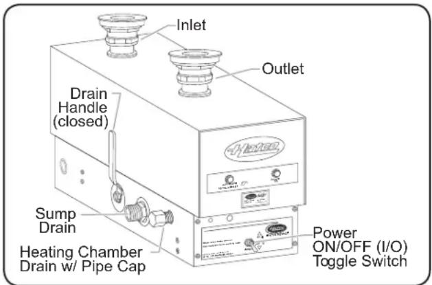
3CS Model
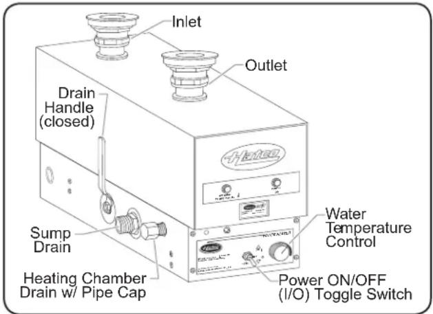
FR Model
SPECIFICATIONS
Plug Configurations
Some FR units are supplied from the factory with an electrical cord and plug installed and are shipped with a receptacle. Plugs and receptacles are supplied according to the applications.
WARNING
ELECTRIC SHOCK HAZARD: Units supplied with an electrical cord, plug, and receptacle require installation of receptacle to on-site electrical system. Connection must be properly grounded and of correct voltage, size, and configuration for electrical specifications of unit. Contact a qualified electrician to determine and install proper electrical connection.
NOTE: The specification label is located on the lower right side on the front of the unit. See label for serial number and verification of unit electrical information.
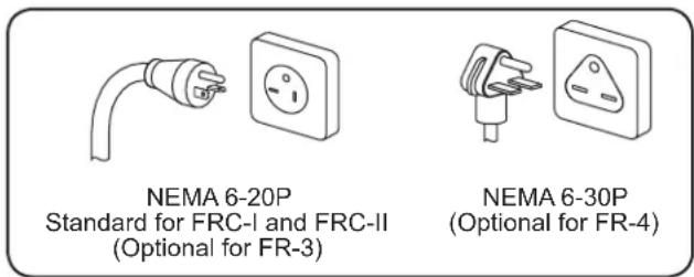
Plug Configurations
| Model 208 V 240 V 220-230 V | |||
| FR-3 NE | MA 6-20P NEMA | 6-20P --- | |
| FR-4 NE | MA 6-30P NEMA | 6-30P --- | |
| FRC-I, -II N | EMA 6-20P NEMA | 6-20P Cord, No Cap | |
Electrical Rating Chart—3CS-X Models
| Model Voltage | Kilowatts(kW) Phase Amps | Wiring Sizing AWG*† | Fuse or Circuit Breaker* | Shipping Weight | ||
| 3CS-3 208 3.0 1 14.4 12 20 24 lbs. (11 kg) | ||||||
| 240 3.0 1 12.5 12 20 24 lbs. (11 kg) | ||||||
| 480 3.0 1 6.3 14 15 24 lbs. (11 kg) | ||||||
| 220–230–240 2.5–2.8–3.0 1 11.5–12–12.5 12 20 24 lbs. (11 kg) | ||||||
| 380–400–415 2.8–3.1–3.4 1 7.4–7.8–8.1 | 14 15 24 lbs. (11 kg) | |||||
| 3CS-4 208 4.5 1 21.6 10 30 24 lbs. (11 kg) | ||||||
| 240 4.5 1 18.8 10 30 24 lbs. (11 kg) | ||||||
| 480 4.5 1 9.4 14 15 24 lbs. (11 kg) | ||||||
| 220–230–240 3.8–4.1–4.5 1 17.2–18–18.8 10 30 24 lbs. (11 kg) | ||||||
| 380–400–415 | 3.8–4.2–4.5 | 1 | 9.9–10.4–10.8 | 14 | 15 | 24 lbs. (11 kg) |
| 380–400–415 | 3.8–4.2–4.5 | 3♦ | 8.6–9–9.4 | 14 | 15 | 24 lbs. (11 kg) |
| 415 4.5 | 3♦ 9.4 14 15 24 lbs. (11 kg) | |||||
| 3CS-6 208 6.0 1 29.8 8 | 40 27 lbs. (12 kg) | |||||
| 240 | 6.0 | 1 | 25 | 8 | 40 | 27 lbs. (12 kg) |
| 480 6.0 1 12.5 12 20 27 lbs. (12 kg) | ||||||
| 220–230–240 5.0–5.5–6.0 1 23–24–25 | 10 30 27 lbs. (12 kg) | |||||
| 380–400–415 5.6–6.3–6.7 1 | 14.8–15.6–16.2 12 20 27 lbs. (12 kg) | |||||
| 208 | 6.0 | 3♦ | 25 | 8 | 40 | 27 lbs. (12 kg) |
| 240 | 6.0 | 3♦ | 21.7 | 10 | 30 | 27 lbs. (12 kg) |
| 380–400–415 | 5.6–6.3–6.7 | 3♦ | 12.9–13.5–14 | 12 | 20 | 27 lbs. (12 kg) |
| 415 | 6.0 | 3♦ | 14 | 12 | 20 | 27 lbs. (12 kg) |
| 480 | 6.0 | 3♦ | 10.8 | 14 | 15 | 27 lbs. (12 kg) |
| 3CS-9 208 9.0 1 43.3 4 | 60 27 lbs. (12 kg) | |||||
| 240 9.0 1 37.5 6 | 50 27 lbs. (12 kg) | |||||
| 480 9.0 1 18.8 10 30 27 lbs. (12 kg) | ||||||
| 220–230–240 | 7.6–8.3–9.0 | 1 | 34.4–35.9–37.5 | 6 | 50 | 27 lbs. (12 kg) |
| 208 | 9.0 | 3♦ | 37.5 | 6 | 50 | 27 lbs. (12 kg) |
| 240 | 9.0 | 3♦ | 32.5 | 8 | 40 | 27 lbs. (12 kg) |
| 480 | 9.0 | 3♦ | 16.2 | 12 | 20 | 27 lbs. (12 kg) |
The shaded areas contain electrical information for International models only.
* Wire size is based on THHN wire for branch circuit protection at 0.91 derate factor. Circuit breakers and fused disconnects are to be mounted remote and wired by contractor. Sizes are based on the 2002 NEC table 310-16. Conduit size based on conductors plus ground wire sizing per Table C1 from Appendix C.
† Based upon THHN wire rated 90°C.
◆ Open Delta-standard construction (Amperage higher than Balanced 3-phase)
NOTE: Shipping Weight includes packaging.
Electrical Rating Chart—3CS-XB Models
| Model Voltage | Kilowatts(kW) Phase Amps | Wiring Sizing AWG*† | Fuse or Circuit Breaker* | Shipping Weight | ||
| 3CS-3B 208 3.0 3 (Bal.) 8.3 14 15 30 lbs. (14 kg) | ||||||
| 240 3.0 3 (Bal.) 7.2 14 15 30 lbs. (14 kg) | ||||||
| 480 3.0 3 (Bal.) 3.6 14 15 30 lbs. (14 kg) | ||||||
| 380–400–415 2.8–3.1–3.4 3 (Bal.) 4.3–4.5–4.7 14 15 30 lbs. (14 kg) | ||||||
| 3CS-4B 208 4.5 3 (Bal.) 12.5 12 20 30 lbs. (14 kg) | ||||||
| 240 4.5 3 (Bal.) 10.8 14 15 30 lbs. (14 kg) | ||||||
| 480 4.5 3 (Bal.) 5.4 14 15 30 lbs. (14 kg) | ||||||
| 380–400–415 3.8–4.1–4.5 3 (Bal.) 5.7–6–6.2 | 14 15 | |||||
| 3CS-6B 208 6.0 3 (Bal.) 18.8 10 30 30 lbs. (14 kg) | ||||||
| 240 6.0 3 (Bal.) 14.4 12 20 30 lbs. (14 kg) | ||||||
| 480 6.0 3 (Bal.) 7.2 14 15 30 lbs. (14 kg) | ||||||
| 380–400–415 | 5.6–6.3–6.7 | 3 (Bal.) | 8.6–9–9.4 | 14 | 15 | 30 lbs. (14 kg) |
| 3CS-9B | 208 | 9.0 | 3 (Bal.) | 25 | 10 | 40 |
| 240 9.0 3 (Bal.) 21.7 10 30 30 lbs. (14 kg) | ||||||
| 440 9.0 3 (Bal.) 11.8 14 15 30 lbs. (14 kg) | ||||||
| 480 9.0 3 (Bal.) 10.8 14 15 30 lbs. (14 kg) | ||||||
| 380–400–415 | 7.5–8.3–9.0 | 3 (Bal.) | 11.4–11.9–12.5 | 12 | 20 | |
The shaded areas contain electrical information for International models only.
* Wire size is based on THHN wire for branch circuit protection at 0.91 derate factor. Circuit breakers and fused disconnects are to be mounted remote and wired by contractor. Sizes are based on the 2002 NEC table 310-16. Conduit size based on conductors plus ground wire sizing per Table C1 from Appendix C.
† Based upon THHN wire rated 90°C.
♦ Open Delta-standard construction (Amperage higher than Balanced 3-phase)
NOTE: Shipping Weight includes packaging.
Electrical Rating Chart—FR-X Models
| Model Voltage | Kilowatts(kW) Phase Amps | Wiring Sizing AWG*† | Fuse or Circuit Breaker* | Shipping Weight | ||
| FR-3 208 3.0 1 14.4 12 20 24 lbs. (11 kg) | ||||||
| 240 3.0 1 12.5 12 20 24 lbs. (11 kg) | ||||||
| 480 3.0 1 6.3 14 15 24 lbs. (11 kg) | ||||||
| 220–230–240 2.5–2.8–3.0 1 11.5–12–12.5 12 20 24 lbs. (11 kg) | ||||||
| 380–400–415 2.8–3.1–3.4 1 7.4–7.8–8.1 | 14 15 24 lbs. (11 kg) | |||||
| 208 3.0 | 3♦ | 8.3 14 15 24 lbs. (11 kg) | ||||
| 240 3.0 | 3♦ | 7.2 14 15 24 lbs. (11 kg) | ||||
| 380–400–415 | 2.8–3.1–3.4 | 3♦ | 4.3–4.5–4.7 | 14 | 26 | 24 lbs. (11 kg) |
| FR-4 208 4.5 1 21.6 10 30 24 lbs. (11 kg) | ||||||
| 240 4.5 1 18.8 10 30 24 lbs. (11 kg) | ||||||
| 480 4.5 1 9.4 14 15 24 lbs. (11 kg) | ||||||
| 220–230–240 3.8–4.1–4.5 1 17.2–18–18.8 10 30 24 lbs. (11 kg) | ||||||
| 380–400–415 | 3.8–4.2–4.5 | 1 | 9.9–10.4–10.8 | 14 | 15 | 24 lbs. (11 kg) |
| 208 4.5 | 3♦ | 12.5 12 20 24 lbs. (11 kg) | ||||
| 240 4.5 | 3♦ | 10.8 14 15 24 lbs. (11 kg) | ||||
| 380–400–415 | 3.8–4.2–4.5 | 3♦ | 8.6–9.0–9.4 | 14 | 15 | 24 lbs. (11 kg) |
| 415 4.5 | 3♦ | 9.4 14 15 24 lbs. (11 kg) | ||||
| 480 4.5 | 3♦ | 5.4 14 15 24 lbs. (11 kg) | ||||
| FR-6 208 6.0 1 28.8 8 | 40 27 lbs. (12 kg) | |||||
| 240 | 6.0 | 1 | 25 | 8 | 40 | 27 lbs. (12 kg) |
| 480 6.0 1 12.5 12 20 27 lbs. (12 kg) | ||||||
| 220–230–240 | 5.0–5.5–6.0 | 1 | 23–24–25 | 8 | 40 | 27 lbs. (12 kg) |
| 380–400–415 | 5.6–6.3–6.7 | 1 | 14.8–15.6–16.2 | 12 | 20 | 27 lbs. (12 kg) |
| 208 | 6.0 | 3♦ | 25 | 8 | 40 | 27 lbs. (12 kg) |
| 240 6.0 | 3♦ | 21.7 10 30 27 lbs. (12 kg) | ||||
| 380–400–415 | 5.6–6.3–6.7 | 3♦ | 12.9–13.5–14 | 12 | 20 | 27 lbs. (12 kg) |
| 415 | 6.0 | 3♦ | 14 | 12 | 20 | 27 lbs. (12 kg) |
| 480 6.0 | 3♦ | 10.8 14 15 27 lbs. (12 kg) | ||||
| 480 6.0 | 3♦ | 7.2 14 15 27 lbs. (12 kg) | ||||
| FR-9 208 9.0 1 43.3 4 | 60 27 lbs. (12 kg) | |||||
| 240 9.0 1 37.5 6 | 50 27 lbs. (12 kg) | |||||
| 480 9.0 1 18.8 10 30 27 lbs. (12 kg) | ||||||
| 220–230–240 | 7.6–8.3–9.0 | 1 | 34.4–35.9–37.5 | 6 | 50 | 27 lbs. (12 kg) |
| 208 | 9.0 | 3♦ | 37.5 | 6 | 50 | 27 lbs. (12 kg) |
| 240 | 9.0 | 3♦ | 32.5 | 8 | 40 | 27 lbs. (12 kg) |
| 480 9.0 | 3♦ | 16.2 12 20 27 lbs. (12 kg) | ||||
| 208 | 9.0 | 3♦ | 25 | 8 | 40 | 27 lbs. (12 kg) |
| 240 9.0 | 3♦ | 21.7 10 30 27 lbs. (12 kg) | ||||
Electrical Rating Chart—FR-XB Models
| Model Voltage | Kilowatts(kW) Phase Amps | Wiring Sizing AWG*† | Fuse or Circuit Breaker* | Shipping Weight | |||
| FR-3B 208 3.0 3 (Bal.) 8.3 14 15 30 lbs. (14 kg) | |||||||
| 240 3.0 3 (Bal.) 7.2 14 15 30 lbs. (14 kg) | |||||||
| 480 3.0 3 (Bal.) 3.6 14 15 30 lbs. (14 kg) | |||||||
| 380–400–415 2.8–3.1–3.4 3 (Bal.) 4.3–4.5–4.7 14 15 30 lbs. (14 kg) | |||||||
| FR-4B 208 4.5 3 (Bal.) 12.5 12 20 30 lbs. (14 kg) | |||||||
| 240 4.5 3 (Bal.) 10.8 14 15 30 lbs. (14 kg) | |||||||
| 480 4.5 3 (Bal.) 5.4 14 15 30 lbs. (14 kg) | |||||||
| 380–400–415 | 3.8–4.1–4.5 | 3 (Bal.) | 5.7–6–6.2 | 14 | 15 | 30 lbs. (14 kg) | |
| FR-6B 208 6.8 3 (Bal.) 18.8 10 30 30 lbs. (14 kg) | |||||||
| 240 6.0 3 (Bal.) 14.4 12 20 30 lbs. (14 kg) | |||||||
| 380 6.0 3 (Bal.) 10.2 14 15 30 lbs. (14 kg) | |||||||
| 380–400–415 | 5.6–6.3–6.7 | 3 (Bal.) | 8.6–9–9.4 | 14 | 15 | 30 lbs. (14 kg) | |
| 480 6.0 3 (Bal.) 7.2 14 15 30 lbs. (14 kg) | |||||||
| FR-9B | 208 | 9.0 | 3 (Bal.) | 25 | 10 | 40 | 30 lbs. (14 kg) |
| 240 9.0 3 (Bal.) 21.7 10 30 30 lbs. (14 kg) | |||||||
| 380 9.0 3 (Bal.) 12.9 12 20 30 lbs. (14 kg) | |||||||
| 440 9.0 3 (Bal.) 11.8 14 15 30 lbs. (14 kg) | |||||||
| 480 9.0 3 (Bal.) 10.8 14 15 30 lbs. (14 kg) | |||||||
| 380–400–415 | 7.6–8.3–9.0 | 3 (Bal.) | 11.5–11.9–12.5 | 12 | 20 | 30 lbs. (14 kg) | |
Electrical Rating Chart—FRC Models
| Model | Voltage | Kilowatts (kW) Phase | Amps | Wiring Sizing AWG*† | Fuse or Circuit Breaker* | Shipping Weight | |
| FRC-I | 208 | 3.0 | 1 | 14.4 | 12 | 20 | 42 lbs. (19 kg) |
| 220–230 | 2.5–2.8 | 1 | 11.5–12 | 14 | 15 | 42 lbs. (19 kg) | |
| 240 | 3.0 | 1 | 12.5 | 12 | 20 | 42 lbs. (19 kg) | |
| FRC-II | 208 | 3.0 | 1 | 14.4 | 12 | 20 | 69 lbs. (31 kg) |
| 220–230 | 2.5–2.8 | 1 | 11.5–12 | 14 | 15 | 69 lbs. (31 kg) | |
| 240 | 3.0 | 1 | 12.5 | 12 | 20 | 69 lbs. (31 kg) | |
The shaded areas contain electrical information for International models only.
* Wire size is based on THHN wire for branch circuit protection at 0.91 derate factor. Circuit breakers and fused disconnects are to be mounted remote and wired by contractor. Sizes are based on the 2002 NEC table 310-16. Conduit size based on conductors plus ground wire sizing per Table C1 from Appendix C.
† Based upon THHN wire rated 90°C.
◆ Open Delta-standard construction (Amperage higher than Balanced 3-phase)
NOTE: Shipping Weight includes packaging.
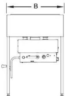
Dimensions
| Model A B | C D E F | |||||
| 3CS-X and FR-X | 16-7/8" (429 mm) | 5-1/2" (140 mm) | 8-1/2" (216 mm) | 2-7/8" (73 mm) | 6-3/4" (171 mm) | 3-3/8" (86 mm) |
| 3CS-XB and FR-XB | 17-1/8" (435 mm) | 4-5/8" (117 mm) | 8-1/2" (216 mm) | 4" (102 mm) | 8" (203 mm) | 4" (102 mm) |
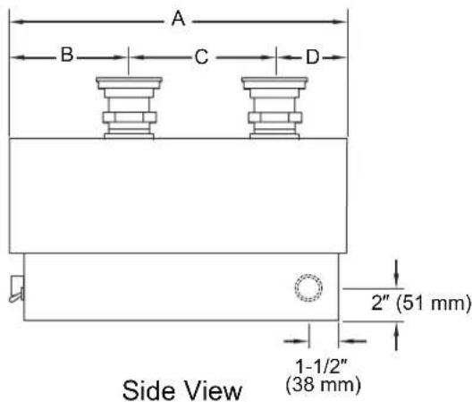
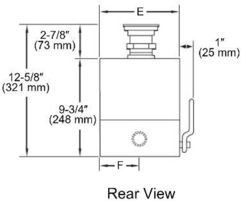
Dimensions—3CS and FR Models
Dimensions—FRC Models
| Model | Width (A) | Depth (B) | Height (C) |
| FRC-I | 12-3/4" (325 mm) | 20-7/8" (530 mm) | 19-7/8" (503 mm) |
| FRC-II | 15-5/8" (397 mm) | 23-3/4" (603 mm) | 34-1/4" (870 mm) |
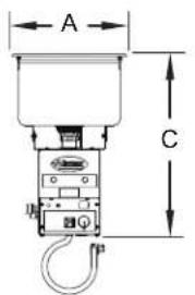
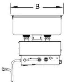
FRC-I
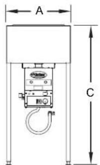
FRC-II
Dimensions—FRC Models
General
Hatco Water Heaters are shipped factory assembled. Care should be taken when unpacking shipping carton to avoid damage to unit and components enclosed.
WARNING
ELECTRIC SHOCK HAZARD:
- Units supplied without an electrical cord and plug require a hardwired connection to on-site electrical system. Connection must be properly grounded and of correct voltage, size, and configuration for electrical specifications of unit. Contact a qualified electrician to determine and install proper electrical connection.
- Units supplied with an electrical cord, plug, and receptacle require installation of receptacle to on-site electrical system. Connection must be properly grounded and of correct voltage, size, and configuration for electrical specifications of unit. Contact a qualified electrician to determine and install proper electrical connection.
- Unit must be installed by qualified, trained installers. Installation must conform to all local electrical and plumbing codes. Installation by unqualified personnel will void the unit warranty and may lead to electric shock or burn, as well as damage to unit and/or its surroundings. Check with local plumbing and electrical inspectors for proper procedures and codes.
- Unit is not weatherproof. Locate the unit indoors where the ambient air temperature is a minimum of 70^ (21°C).
FIRE HAZARD: Install unit with a minimum of 3-1/2" (89 mm) of space from bottom of unit to all combustible surfaces to prevent combustion.
- Remove the unit from the box.
NOTE: To prevent delay in obtaining warranty coverage, complete online warranty registration. See the IMPORTANT OWNER INFORMATION section for details.
- Remove tape and protective packaging from all surfaces of unit.
Sizing Information
Hatco recommends the following guidelines be used to ensure proper operation and sanitation.
For 3CS Models in a Sink Heater Application
- Minimum of 2000 watts per square foot (2.2 watts per sq. cm) of vessel top.
For FR Models in a Bain-Marie or Steam Table Application
- Minimum 750 watts per square foot (0.8 watts per sq. cm) of vessel top.
For FR Models in a Food Rethermalizer Application
- Minimum 2000 watts per square foot (2.2 watts per sq. cm) of vessel top.
NOTE: Use one heater for a Bain-Marie up to 6' (1829 mm) long. Units over 6' (1829 mm) require a minimum of two heaters.
Installing 3CS and FR Models
A paper template is shipped with the unit and is used to locate the sink strainer holes. Use the following procedure to mount to the sink or holding vessel.
CAUTION
BURN HAZARD: Drain water may reach temperatures in excess of 200^ F ( 93^ C). Use appropriate plumbing materials when installing drain.
Do not use extension pipes on the inlet and outlet connections on water heater units. Poor performance or unsafe conditions may occur.
NOTE: FR Models should be installed with a perforated water baffle (not supplied with unit) to distribute the heated water properly. The baffle should be 3/4" (19 mm) high with a divider wall between the inlet and outlet. The baffle should also have 3/4" (19 mm) holes around the periphery every 6" (152 mm).
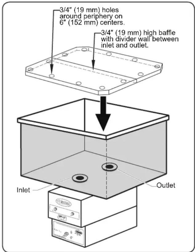
Water Baffle Installation (FR Models)
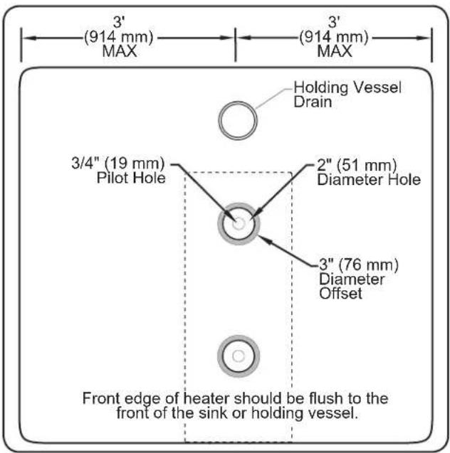
Top View of Sink or Holding Vessel
NOTE: The dotted lines in the image above indicate the position of the unit under the sink or holding vessel.
- Locate the template on the bottom of the sink or holding vessel.
- The template should be positioned exactly above where the water heater will be positioned below the sink or holding vessel.
- Make sure the front edge of the template is flush with the front edge of the sink or holding vessel.
- FR Models should be positioned with no more than 3' (914 mm) on either side when mounted under the sink or holding vessel.
- Center punch and drill a 3/4" (19 mm) pilot hole at each of the two center marks on the template.
NOTE: The pilot holes are for cutting larger holes with a knockout hole punch.
- Remove the template and cut a 2" (51 mm) diameter hole at each pilot hole location using a knockout hole punch.
- Make a 1/8" (3 mm) offset around each 2" (51 mm) diameter hole. The offset should be a diameter of 3" (76 mm) centered around the hole.
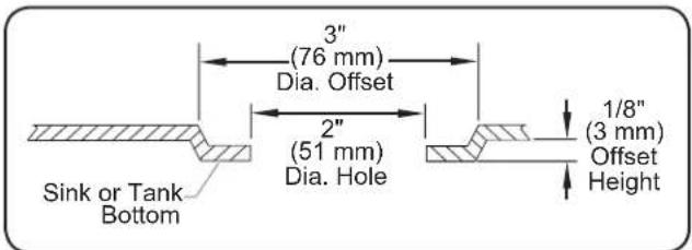
Side View of Hole and Offset
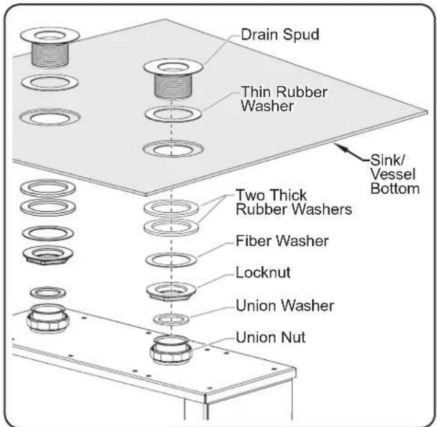
Installing the Drain Spud Assembly
- Unscrew the drain spud assembly from the welded pipe on the heater.
- Unscrew the locknut from the drain spud assembly and slide off all of the washers except the thin rubber washer.
- With only the thin rubber washer attached to the drain spud, slide the drain spud through the sink hole from above.
- Secure the drain spud assembly to the sink or holding vessel.
a. From under the sink, slide the two thick rubber washers followed by the fiber washer onto the drain spud.
b. Screw the locknut (flat side up) onto the drain spud. - Repeat steps 5–8 for the other spud assembly.
- Secure the unit to the sink or holding vessel. Two people may be required for this step.
a. Position the unit under the two spud assemblies.
NOTE: Make sure the union washers are positioned properly inside the union nuts and are not crimped.
b. Screw the union nut to the threaded drain spud assembly.
NOTICE
Do not use excessive force when tightening unions or nuts. Over-tightening and excessive force may cause leaks.
- Tighten the union nuts and locknuts securely.
- Verify drain valve handle is in closed (vertical) position.
- Fill the sink or holding vessel with water and check for leaks.
NOTE: A 3/4" (19 mm) hose or pipe may be connected to the sump drain and run to an open site drain. The sump drain should not be permanently connected to the sanitary drain system. Check local plumbing code for proper drain installation. See the MAINTENANCE section for more information.
Installing FRC Models
The FRC-I Model mounts into a countertop. Use the following procedure to mount the unit to the countertop.
NOTE: FRC-II Models are shipped pre-assembled in a stand from the factory.
BURN HAZARD: Drain water may reach temperatures in excess of 200°F (93°C). Use appropriate plumbing materials when installing drain.
Do not use extension pipes on the inlet and outlet connections on water heater units. Poor performance or unsafe conditions may occur.
- Cut the countertop opening. Refer to the Countertop Cutout figure in this section for more information.
a. Measure and mark the countertop for the cutout. (19-7/8" [505 mm] x 11-7/8" [301 mm]). - The corners need a 1" (25 mm) x 45° chamfer for the 5/16" (8 mm) mounting holes.
b. Cutout the countertop using the markings. - Drill the 5/16" (8 mm) mounting holes at each chamfer corner. Refer to the Countertop Cutout figure in this section for dimensions.
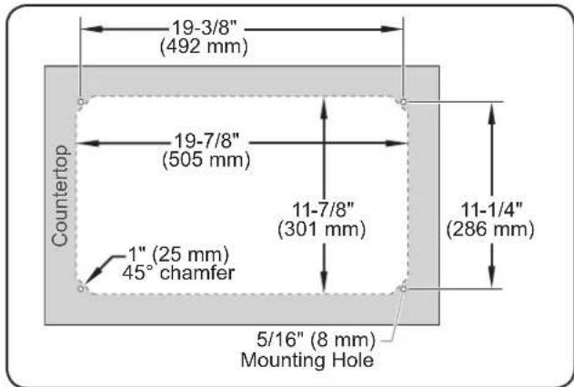
Top View of Countertop Cutout
NOTE: The dotted lines in the Countertop Cutout figure mark the area to cut out.
- Apply a bead of NSF-approved sealant between the countertop material and the mounting flange on the unit. The sealant must be rated for use at a minimum temperature of 250^ F ( 121^ C).
- Place the unit into the countertop opening.
a. Align the studs on the bottom of the sink into the 5/16" (8 mm) mounting holes at each chamfer corner.
b. Fasten with the included nylock nuts.
NOTE: There must be a minimum of 30" (762 mm) clearance below the countertop to accommodate the tank, heater, and drain assembly.
- Remove any excess sealant.
Electrical Information
Hatco 3CS and FR Model Water Heaters are available for operation on standard power systems. Check the specification label for the proper power supply.
All internal electrical connections have been made at the factory. Refer to the appropriate "Electrical Rating Chart" for wiring and voltage requirements.
Turn OFF power switch, disconnect unit from power source, and allow unit to cool before performing any cleaning, adjustments, or maintenance.
NOTICE
Connect Water Heaters to the same power supply as indicated on the specification decal only. Connecting units to an incorrect power supply will void the product warranty and may damage the equipment.
Hardwired Connections
Conductors from a properly sized fused disconnect switch or circuit breaker must be wired to the heater in accordance with local electrical codes.
- Remove the bottom cover screws and remove the bottom cover.
- Locate the heater terminal block inside the unit.
NOTE: 3CS and FR Models rated for 6 and 9 kW (wired for three phase open delta) can be field converted to single phase. Refer to the electrical diagram supplied with unit or contact Hatco for assistance.
- Bring power leads from a properly sized disconnect switch or circuit breaker through the knockouts provided on the unit, and connect to the terminal block.
- Use copper wire only. Tighten connections properly to a minimum of 40 inch pounds.
NOTE: Refer to "Dimensions" in the SPECIFICATION section for knockout locations.
NOTE: Due to the rigors of transportation all connections should be checked for tightness before heater is put into operation.
-
A grounding lug is provided near the terminal block. An equipment grounding conductor must be properly connected to it.
-
Replace and secure bottom cover using previously removed screws.
Cord, Plug, and Receptacle Connections
FR-3 and FR-4 water heaters may be supplied with an optional electrical cord, plug, and receptacle. FR-3 Models use a NEMA 6-20R receptacle, FR-4 Models use a NEMA 6-30R receptacle.
All FRC Models are shipped with cords.
ELECTRIC SHOCK HAZARD: Units supplied with an electrical cord, plug, and receptacle require installation of receptacle to on-site electrical system. Connection must be properly grounded and of correct voltage, size, and configuration for electrical specifications of unit. Contact a qualified electrician to determine and install proper electrical connection.
General
Use the following procedures to operate a water heater.

WARNING
Read all safety messages in the IMPORTANT SAFETY INFORMATION section before operating this equipment.

CAUTION
BURN HAZARD:
- Water in holding vessel may reach temperatures in excess of 190^ (88°C). Use appropriate protection when operating unit.
- Units are designed to heat water up to 190°F (88°C). DO NOT set temperature controls to a setting higher than 190°F (88°C). Water over 190°F (88°C) is very active and could splash onto operator causing serious burns or injury.
Do not add cold food for rethermalizing while holding hot food. The hot food will not maintain proper serving temperature.
NOTICE
Make sure a minimum of 0.5 gallons (2 liters) of water is in unit before plugging in or operating. Operating unit with less than 2 liters of water will cause unit to overheat.
Startup
- Check that the fused disconnect switch or circuit breaker is on, or if equipped with power cord and plug make sure unit is plugged into a properly grounded receptacle of the correct voltage, size, and plug configuration. See the SPECIFICATIONS section for details.
- Make sure that the drain cap is securely tightened to the heating chamber drain.
- Close sump drain by moving the drain handle toward the front of the unit until it stops.
- Fill the sink or holding vessel with hot tap water to the normal operating level.
NOTE: FR Models should be installed with a perforated water baffle (not supplied with unit) to distribute the heated water properly. The baffle should be 3/4" (19 mm) high with a divider wall between the inlet and outlet. The baffle should also have 3/4" (19 mm) holes around the periphery every 6" (152 mm).
- Move the Power ON/OFF (I/O) toggle switch to the ON (I) position.
- The POWER ON light will glow indicating power is supplied.
-
On FR Models, set the water temperature control to the desired temperature.
-
Wait until the water reaches the desired temperature.
-
FR Models: The WATER AT TEMPERATURE light will glow when water is at the control temperature.
- 3CS models: An optional WATER AT TEMPERATURE light or an optional temperature monitor can be used to determine when a sanitizing temperature is reached.
Energy Cut-Off Switch (ECO)
All Hatco water heaters have a built-in Energy Cut-Off switch (ECO) that will shut "OFF" the power if the unit should overheat.
If the Energy Cut-Off switch has activated, a low water level may be the cause. To continue operation the unit needs to be reset.
To reset FR Models:
- Fill to the proper water level. Push the high temperature limit switch on the front of the heater.
To reset 3CS Models:
- Fill to the proper water level. Turn the Power ON/OFF (I/O) switch to OFF (O) position and then to the ON (I) position.
NOTE: The ECO on FR Models does not protect the heater when both reservoirs are drained. The optional low-water cut-off (LWCO) system disconnects power to the heating elements if water is drained.
NOTE: The ECO on 3CS Models does not protect the heating elements when both reservoirs are drained. Dry firing of unit will damage the heating elements and is not covered under warranty.
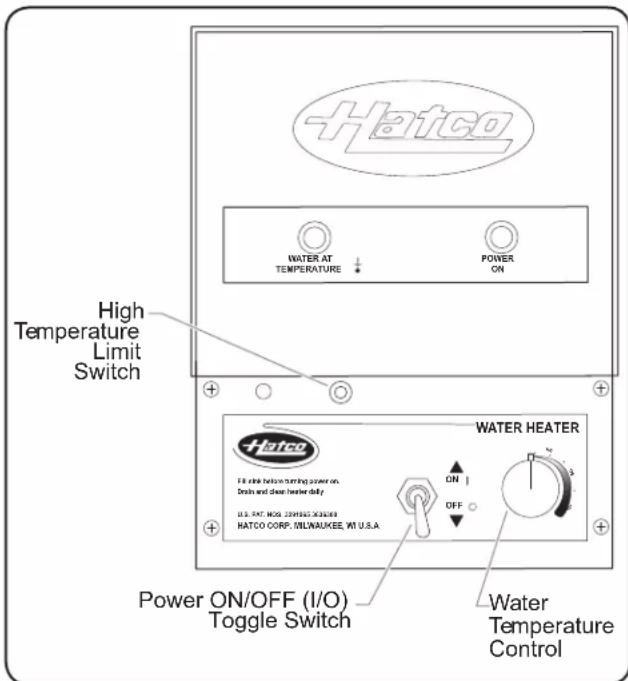
Control Panel (FR Model shown)
General
Hatco Water Heaters are designed for maximum durability and performance with minimum maintenance.
WARNING
ELECTRIC SHOCK HAZARD:
- Turn OFF power switch, unplug power cord/turn off power at circuit breaker, and allow unit to cool before performing any cleaning, adjustments, or maintenance.
- DO NOT submerge or saturate with water. Unit is not waterproof. Do not operate if unit has been submerged or saturated with water.
- Do not steam clean or use excessive water on unit.
- Do not clean unit when it is energized or hot.
This unit has no “user-serviceable” parts. If service is required on this unit, contact an Authorized Hatco Service Agent or contact the Hatco Service Department at 800-558-0607 or 414-671-6350.
Use only Genuine Hatco Replacement Parts when service is required. Failure to use Genuine Hatco Replacement Parts may subject operators of the equipment to hazardous electrical voltage, resulting in electrical shock or burn. Genuine Hatco Replacement Parts are specified to operate safely in the environments in which they are used. Some aftermarket or generic replacement parts do not have the characteristics that will allow them to operate safely in Hatco equipment.
Recommended Cleaning Schedule
Complete cleaning and power flushing should be done:
- On a daily basis.
- Whenever food accumulates in the tank.
- Whenever a non-food spill occurs.
- Whenever the unit is to be stored or shipped, especially in freezing temperatures.
Helpful Hints
- Keep inlet and outlet free of debris.
- Keep perforated water baffle (not supplied) in place and free of debris (FR units only).
- Delime unit using a non-corrosive deliming solution.
Daily Cleaning
Use the following procedure to clean the unit. The unit should be cleaned daily. Lime and mineral deposits should be removed regularly. The flush hose kit accessory is recommended to clean the unit properly.
- Move the POWER ON/OFF (I/O) toggle switch to the OFF (O) position and allow the unit and water to cool.
- Connect one end of a drain hose onto the sump drain with the other end in a bucket or open site drain in a manner according to local plumbing codes.
- Place rubber stopper into the inlet strainer.
-
Open the sump drain by moving the drain handle backward until it is in the horizontal position. Water will now flow from the drain hose.
-
Attach the flush hose with adapter to a fresh water supply and position adapter end into outlet strainer. Flush with water until discharge from sump drain is clear.
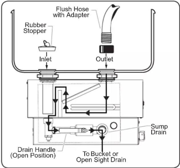
Draining the Sump Reservoir
- Close the sump drain by moving the drain handle towards the front of the unit until it stops.
- Place the rubber stopper into the outlet strainer and the flush hose in the inlet.
- Place a bucket under the heating chamber drain and remove the drain cap. Flush water through the unit until discharge water from heating compartment is clear.
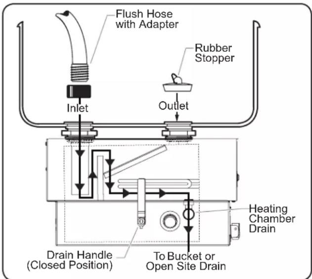
Draining the Heating Reservoir
- Turn the water supply off and allow the unit to finish draining.
- Replace the drain cap and tighten to stop any leaks.
- Remove the rubber stopper and the flush hose.
Remove Lime and Mineral Deposits
The amount of lime and mineral content in the water and how often the unit is operated will dictate how often the unit needs to be delimed.
Units used with water that contains high lime and mineral content may require deliming on a daily basis.
Use the following procedure to remove lime and mineral deposits.
-
Move the Power ON/OFF (I/O) toggle switch to the OFF (O) position and allow the unit and water to cool.
-
Connect one end of a drain hose onto the sump drain with the other end in a bucket or open site drain in a manner according to local plumbing codes.
-
Remove drain cap from side of unit and drain all water from heating compartment.
-
Replace the drain cap on the side of unit.
-
Close the sump drain by moving the drain handle toward the front of the unit until it stops.
-
Add a mixture of 75% water and 25% white vinegar into the heat tank through the sink strainer assemblies. Do not use flavored vinegar. Allow the unit to stand with the mixture in the reservoir for an appropriate period of time.
NOTE: The amount of lime and mineral content in the water and how often the unit is operated will dictate how often the unit needs to be delimed. Units used with water that contains high lime and mineral content may require deliming on a daily basis.
NOTE: The time required will vary depending on the solution used and amount of deposits in reservoir.
NOTE: Product failure caused by liming or sediment buildup is not covered under warranty.
NOTE: The delimer used should be a safe, non-toxic, non-corrosive solution. Follow the delimer's instructions.
-
After cleaning, drain all expended solution from the unit through the sump drain and heating chamber drain.
-
Thoroughly flush heater through the front and rear openings with fresh water for several minutes until discharge is clear.
-
Re-install drain cap and close sump drain.
-
Upon visual inspection, if tank is not thoroughly clean, repeat steps 6-9.
Draining Heater For Service Protection
Use the following procedure when shutting down the unit for long periods of time.
- Move the Power ON/OFF (I/O) toggle switch to the OFF (O) position.
- Perform the entire "Cleaning" procedure in this section.
- Turn off the electrical power supply to the heater.
- Make sure the water has been drained from the unit as well as the sink or holding vessel.
NOTE: Heating element chamber holds from 2-1/2 up to 4-1/2 quarts of water, depending upon model.
Resetting the Energy Cut-Off Switch (ECO)
FR Models are equipped with a manually-resettable high temperature limit switch that prevents the water temperature from getting dangerously high.
If the water inside the unit becomes too hot, the high temperature limit switch will shut the unit off.
To reset the energy cut-off switch after it activates, use the following procedure.
- Move the Power ON/OFF (I/O) toggle switch to the OFF (O) position.
- Press the high temperature limit switch until it clicks. The switch is a small red button located on the front of the unit.
- The high temperature limit switch is now reset.
NOTE: 3CS models do not have a manually reset on the high temperature limit switch. If the unit shuts off due to high water temperature, turn the unit off and let it cool.
NOTE: Contact an Authorized Service Agent if the high temperature limit continues to trip.
TROUBLESHOOTING GUIDE
Troubleshooting Questions?
If you continue to have problems resolving an issue, please contact the nearest Authorized Hatco Service Agency or Hatco for assistance. To locate the nearest Service Agency, log onto the Hatco website at www.hatcocorp.com and click on Find Service Agent, or contact the Hatco Parts and Service Team at:
Telephone: 800-558-0607 or 414-671-6350
e-mail: support@hatcocorp.com
WARNING
This unit must be serviced by trained and qualified personnel only. Service by unqualified personnel may lead to electric shock or burn.
WARNING
ELECTRIC SHOCK HAZARD: Turn OFF power switch, unplug power cord/turn off power at circuit breaker, and allow unit to cool before performing any cleaning, adjustments, or maintenance.
| Symptom Probable | Cause Corrective Action | |
| Water temperature too high. The water | temperature control (FR only) is set too high. | Adjust the water temperature control (FR only) to the desired temperature. |
| Water temperature too low. Water heaters | need approximately 30 minutes to reach a safe sanitizing temperature. | Wait 30 minutes for the unit to reach proper temperature. |
| The water temperature control (FR only) is set too low. | Adjust the water temperature control (FR only) to the desired temperature. | |
| Heating elements burn out. The sink or holding vessel is dry or has a low level of water. | Fill the sink or holding vessel with water to normal operating level. | |
| Deposits built up in heater are restricting water flow. | ||
| The sink or holding vessel leaks. | Fittings are too loose or too tight. | Adjust any fittings that may be causing the unit to leak. Replace gasket, if necessary. |
| The Power ON/OFF (I/O) toggle switch is in the ON (I) position but the unit is not heating the water. | The Low-Water Cut-Off switch was activated. The | unit was shutdown due to a low water level or from being overheated. Fill the heater to the proper water level and turn the Power ON/OFF (I/O) toggle switch to the OFF (O) position and then to the ON (I) position. |
| Fuses may be blown, the circuit breaker may be tripped, or the power cord may be unplugged. | Check for proper fuse sizing and replace fuses, check/reset circuit breaker, and/or check/replace power cord. | |
OPTIONS AND ACCESSORIES
Temperature Monitor
An optional temperature monitor is available for 3CS Models. The temperature monitor displays the current water temperature.
Temperature Light
An optional temperature light is available for 3CS Models. The temperature light glows when the water temperature reaches safe sanitizing temperature.
Low-Water Cut-Off
An optional low-water cut-off (LWCO) feature is available for FR Models. This feature prevents element burn out from low water conditions.
Flush Hose Kit
The Flush Hose Kit is available for 3CS and FR Models and is used to power flush the unit to keep it working at peak efficiency. The kit consists of a drain stopper and a hose with adapter.
Security Package
A security package is a factory-installed option for 3CS and FR Models. A security package contains Torx ^® screws and a control cover.
Cord and Plug with Receptacle
An optional cord and plug with the matching receptacle is available for FR-3 and FR-4 Models. Refer to "Plug Configurations" in the SPECIFICATION section for more information.
NOTE: Optional items are not field retrofittable.
1. PRODUCT WARRANTY
Hatco warrants the products that it manufactures (the "Products") to be free from defects in materials and workmanship, under normal use and service, for a period of one (1) year from the date of purchase when installed and maintained in accordance with Hatco's written instructions or 18 months from the date of shipment from Hatco. Buyer must establish the Product's purchase date by registering the Product with Hatco or by other means satisfactory to Hatco in its sole discretion.
Hatco warrants the following Product components to be free from defects in materials and workmanship from the date of purchase (subject to the foregoing conditions) for the period(s) of time and on the conditions listed below:
a) One (1) Year Parts and Labor PLUS One (1) Additional Year Parts-Only Warranty:
Conveyor Toaster Elements (metal sheathed) Drawer Warmer Elements (metal sheathed) Drawer Warmer Drawer Rollers and Slides Strip Heater Elements (metal sheathed) Display Warmer Elements (metal sheathed air heating) Holding Cabinet Elements (metal sheathed air heating) Heated Well Elements—HW and HWB Series (metal sheathed)
b) Two (2) Year Parts and Labor Warranty: Induction Ranges
c) One (1) Year Parts and Labor PLUS Four (4) Years Parts-Only Warranty: 3CS and FR Tanks
d) One (1) Year Parts and Labor PLUS Nine (9) Years Parts-Only Warranty on: Electric Booster Heater Tanks Gas Booster Heater Tanks
e) Ninety (90) Day Parts-Only Warranty: Replacement Parts
THE FOREGOING WARRANTIES ARE EXCLUSIVE AND IN LIEU OF ANY OTHER WARRANTY, EXPRESSED OR IMPLIED, INCLUDING BUT NOT LIMITED TO ANY IMPLIED WARRANTY OF MERCHANTABILITY OR FITNESS FOR A PARTICULAR PURPOSE OR PATENT OR OTHER INTELLECTUAL PROPERTY RIGHT INFRINGEMENT. Without limiting the generality of the foregoing, SUCH WARRANTIES DO NOT COVER: Coated incandescent light bulbs, fluorescent lights, heat lamp bulbs, coated halogen light bulbs, halogen heat lamp bulbs, xenon light bulbs, LED light tubes, glass components, and fuses; Product failure in booster tank, fin tube heat exchanger, or other water heating equipment caused by liming, sediment buildup, chemical attack, or freezing; or Product misuse, tampering or misapplication, improper installation, or application of improper voltage.
2. LIMITATION OF REMEDIES AND DAMAGES
Hatco's liability and Buyer's exclusive remedy hereunder will be limited solely, at Hatco's option, to repair or replacement using new or refurbished parts or Product by Hatco or a Hatco-authorized service agency (other than where Buyer is located outside of the United States, Canada, United Kingdom, or Australia, in which case Hatco's liability and Buyer's exclusive remedy hereunder will be limited solely to replacement of part under warranty) with respect to any claim made within the applicable warranty period referred to above. Hatco reserves the right to accept or reject any such claim in whole or in part. In the context of this Limited Warranty, "refurbished" means a part or Product that has been returned to its original specifications by Hatco or a Hatco-authorized service agency. Hatco will not accept the return of any Product without prior written approval from Hatco, and all such approved returns shall be made at Buyer's sole expense. HATCO WILL NOT BE LIABLE, UNDER ANY CIRCUMSTANCES, FOR CONSEQUENTIAL OR INCIDENTAL DAMAGES, INCLUDING BUT NOT LIMITED TO LABOR COSTS OR LOST PROFITS RESULTING FROM THE USE OF OR INABILITY TO USE THE PRODUCTS OR FROM THE PRODUCTS BEING INCORPORATED IN OR BECOMING A COMPONENT OF ANY OTHER PRODUCT OR GOODS.
Informations relatives aux dimensions....28
Informations relatives aux dimensions
Use only Genuine Hatco Replacement Parts when service is required. Failure to use Genuine Hatco Replacement Parts may subject operators of the equipment to hazardous electrical voltage, resulting in electrical shock or burn. Genuine Hatco Replacement Parts are specified to operate safely in the environments in which they are used. Some aftermarket or generic replacement parts do not have the characteristics that will allow them to operate safely in Hatco equipment.
1. GARANTIE DU PRODUIT
Service Solutions Group
Phoenix 602-234-2443
Byassee Equipment Co.
Phoenix 602-252-0402
CALIFORNIA
Industrial Electric
Commercial Parts & Service, Inc.
Huntington Beach 714-379-7100
Chapman Appl. Service
San Diego 619-298-7106
P & D Appliance
Commercial Parts & Service, Inc.
S. San Francisco 650-635-1900
COLORADO
Hawkins Commercial Appliance
Englewood 303-781-5548
FLORIDA
Whaley Foodservice Repair
Jacksonville 904-725-7800
Whaley Foodservice Repair
Orlando 407-757-0851
B.G.S.I
Pompano Beach 954-971-0456
Comm. Appliance Service
Tampa 813-663-0313
GEORGIA
TWC Services
Mableton 770-438-9797
Heritage Service Group
Norcross 866-388-9837
Southeastern Rest. Svc
Norcross 770-446-6177
HAWAII
Burney's Comm. Service, Inc.
Honolulu 808-848-1466
Food Equip Parts & Service
Honolulu 808-847-4871
ILLINOIS
Parts Town
Lombard 708-865-7278
Eichenauer Elec. Service
Decatur 217-429-4229
Midwest Elec. Appl. Service
Elmhurst 630-279-8000
Cone's Repair Service
Moline 309-797-5323
INDIANA
GCS Service
Indianapolis 800-727-8710
IOWA
Goodwin Tucker Group
Des Moines 515-262-9308
KENTUCKY
Service Solutions Group
Lexington 859-254-8854
Service Solutions Group
Louisville 502-451-5411
LOUISIANA
Chandlers Parts & Service
Baton Rouge 225-272-6620
MARYLAND
Electric Motor Service
Baltimore 410-467-8080
GCS Service
Silver Spring 301-585-7550
MASSACHUSETTS
Ace Service Co., Inc.
Needham 781-449-4220
MICHIGAN
Bildons Appliance Service
Detroit 248-478-3320
Commercial Kitchen Service
Bay City 989-893-4561
Midwest Food Equip. Service
Grandville 616-261-2000
MINNESOTA
GCS Service
Minnetonka 800-822-2303
x20365
MISSOURI
General Parts
Kansas City 816-421-5400
Commercial Kitchen Services
St. Louis 314-890-0700
Kaemmerlen Parts & Service
St. Louis 314-535-2222
NEBRASKA
Anderson Electric
Omaha 402-341-1414
NEVADA
Burney's Commercial
Las Vegas 702-736-0006
Hi. Tech Commercial Service
N. Las Vegas 702-649-4616
NEW JERSEY
Jay Hill Repair
Fairfield 973-575-9145
Service Plus
Flanders 973-691-6300
NEW YORK
Alpro Service Co.
Maspeth 718-386-2515
Appliance Installation
Buffalo 716-884-7425
Duffy's Equipment Services, Inc.
Buffalo 800-836-1014
3Wire Northern
Plattsburgh 800-634-5005
Duffy's Equipment Services, Inc.
Sauquoit 800-836-1014
J.B. Brady, Inc.
Syracuse 315-422-9271
NORTH CAROLINA
Authorized Appliance
Charlotte 704-377-4501
OHIO
Akron/Canton Comm. Svc. Inc.
Akron 330-753-6634
Service Solutions Group
Cincinnati 513-772-6600
Commercial Parts and Service
Columbus 614-221-0057
Electrical Appl. Repair Service
Brooklyn Heights 216-459-8700
E. A. Wichman Co.
Toledo 419-385-9121
OKLAHOMA
Hagar Rest. Service, Inc
Oklahoma City 405-235-2184
Krueger, Inc.
Oklahoma City 405-528-8883
OREGON
Ron's Service, Inc.
Portland 503-624-0890
PENNSYLVANIA
Elmer Schultz Services
Philadelphia 215-627-5401
FAST Comm. Appl. Service
Philadelphia 215-288-4800
Appliance Installation & Service
Pittsburgh 412-809-0244
K & D Service Co.
Harrisburg 717-236-9039
Electric Repair Co
Reading 610-376-5444
RHODE ISLAND
Marshall Electric Co.
Providence 401-331-1163
SOUTH CAROLINA
Whaley Foodservice Repair
Lexington 803-996-9900
TENNESSEE
Camp Electric
Memphis 901-527-7543
TEXAS
GCS Service
Fort Worth 800-433-1804
Armstrong Repair Servi
Houston 713-666-7100
Cooking Equipment Specialist
Mesquite 972-686-6666
Commercial Kitchen Repair Co
San Antonio 210-735-2811
UTAH
La Monica's Rest. Equip. Service
Murray 801-263-3221
VIRGINIA
Daubers
Norfolk 757-855-4097
Daubers
Springfield 703-866-3600
WASHINGTON
3Wire Restaurant Appliance
Seattle 800-207-3146
WISCONSIN
A.S.C., Inc.
Madison 608-246-3160
A.S.C., Inc.
Milwaukee 414-543-6460
CANADA
ALBERTA
Key Food Equipment Service
Edmonton 780-438-1690
BRITISH COLUMBIA
Key Food Equipment Service
Vancouver 604-433-4484
Key Food Equipment Service
Victoria 250-920-4888
MANITOBA
Air Rite, Inc.
Winnipeg 204-895-2300
NEW BRUNSWICK
EMR Services Ltd
Moncton 506-855-4228
ONTARIO
R.G. Henderson Ltd.
Toronto 416-422-5580
Choquette - CKS, Inc.
Ottawa 613-739-8458
QUÉBEC
Choquette - CKS, Inc.
Montreal 514-722-2000
Choquette - CKS, Inc.
Québec City 418-681-3944
UNITED KINGDOM
Marren Group
Northants +44(0)1933 665313
HATCO CORPORATION
P.O. Box 340500
Milwaukee, WI 53234-0500 U.S.A.
800-558-0607 414-671-6350
support@hatcocorp.com
www.hatcocorp.com
Register your unit online!
See IMPORTANT OWNER INFORMATION section for details.
- WARNING
- ADVERTENCIA
- IMPORTANT OWNER INFORMATION
- Register your unit!
- INTRODUCTION
- ELECTRIC SHOCK HAZARD:
- FIRE HAZARD:
- CAUTION
- BURN HAZARD:
- NOTICE
- NSF Criteria
- MODEL DESIGNATIONS
- All Models
- 3CS Models
- FR Models
- FRC-I and FRC-II Models
- SPECIFICATIONS
- Plug Configurations
- General
- Sizing Information
- For 3CS Models in a Sink Heater Application
- For FR Models in a Bain-Marie or Steam Table Application
- For FR Models in a Food Rethermalizer Application
- Installing 3CS and FR Models
- Do not use excessive force when tightening unions or nuts. Over-tightening and excessive force may cause leaks.
- Installing FRC Models
- Electrical Information
- Hardwired Connections
- Cord, Plug, and Receptacle Connections
- Startup
- Energy Cut-Off Switch (ECO)
- Recommended Cleaning Schedule
- Helpful Hints
- Daily Cleaning
- Remove Lime and Mineral Deposits
- Draining Heater For Service Protection
- Resetting the Energy Cut-Off Switch (ECO)
- TROUBLESHOOTING GUIDE
- Troubleshooting Questions?
- OPTIONS AND ACCESSORIES
- Temperature Monitor
- Temperature Light
- Low-Water Cut-Off
- Flush Hose Kit
- Security Package
- Cord and Plug with Receptacle
- PRODUCT WARRANTY
- LIMITATION OF REMEDIES AND DAMAGES
- Informations relatives aux dimensions
- GARANTIE DU PRODUIT
- CALIFORNIA
- COLORADO
- FLORIDA
- GEORGIA
- HAWAII
- ILLINOIS
- INDIANA
- IOWA
- KENTUCKY
- LOUISIANA
- MARYLAND
- MASSACHUSETTS
- MICHIGAN
- MINNESOTA
- MISSOURI
- NEBRASKA
- NEVADA
- NEW JERSEY
- NEW YORK
- NORTH CAROLINA
- OHIO
- OKLAHOMA
- OREGON
- PENNSYLVANIA
- RHODE ISLAND
- SOUTH CAROLINA
- TENNESSEE
- TEXAS
- UTAH
- VIRGINIA
- WASHINGTON
- WISCONSIN
- CANADA
- ALBERTA
- BRITISH COLUMBIA
- MANITOBA
- NEW BRUNSWICK
- ONTARIO
- QUÉBEC
- UNITED KINGDOM
Brand : Hatco
Model : FR4B
Category : Heating