
Tread XL Baja Chase Edition - Wall mount GARMIN - Free user manual and instructions
Find the device manual for free Tread XL Baja Chase Edition GARMIN in PDF.

| Product Type | Off-road GPS Navigator with Mounting Base |
| Brand | Garmin |
| Model | Tread XL Baja Chase Edition |
| Category | Wall Mount (Vehicle Base) |
| Power Supply | 12–24 V DC via vehicle power cable; built-in lithium-ion battery |
| Display | Touchscreen |
| Connectivity | Wi-Fi, Bluetooth, USB port, microSD reader, external GNSS and Iridium antennas |
| Main Functions | Off-road GPS navigation, inReach satellite messaging, SOS, VHF radio (Group Ride Radio), team tracking, Garmin PowerSwitch, Tread Audio, track recording, topographic maps and BirdsEye imagery |
| Satellite Reception | GPS + external GNSS (antenna included); Iridium for satellite messaging |
| Antenna Ports | 1 x GNSS (BNC), 1 x Iridium |
| Storage | microSD (4–256 GB, FAT32) |
| Operating Temperature | -20 to 70 °C (navigation device) |
| Storage Temperature | -40 to 85 °C |
| Water Resistance (Base) | Not specified but compatible with outdoor installation |
| Maintenance and Cleaning | Clean the external casing with a soft cloth; touchscreen with screen cleaner; avoid abrasive products |
| Safety | SOS button under cover, screen lock, power save mode |
| Spare Parts and Repairability | External antennas, cables, mounts, base; consult garmin.com for accessories |
| General Information | 92-page user manual available in PDF; translation available on request |
Frequently Asked Questions - Tread XL Baja Chase Edition GARMIN
User questions about Tread XL Baja Chase Edition GARMIN
0 question about this device. Answer the ones you know or ask your own.
Ask a new question about this device
Download the instructions for your Wall mount in PDF format for free! Find your manual Tread XL Baja Chase Edition - GARMIN and take your electronic device back in hand. On this page are published all the documents necessary for the use of your device. Tread XL Baja Chase Edition by GARMIN.
USER MANUAL Tread XL Baja Chase Edition GARMIN
natural_image
Line drawing of a rectangular electronic device with a top handle and front panel (no text or symbols)TREAD® XL - BAJA RACE EDITION TREAD XL - BAJA CHASE EDITION
Chase Edition.... 14
Tread Audio Box Mounting Considerations.... 65
Mounting the Tread Audio Box Black Box Device.... 65
Connections.... 66 Identification de port.... 66
Speaker and LED Wiring Harness Wire and Connector Identification.... 67
RCA Wiring Harness Wire and Connector Identification......68
text_image
Labeled diagram of a device rear panel with numbered components and a central display screen showing status bar.text_image
① ② GARMIN ③ ④ ⑤ ⑥text_image
Diagram of a cable or wire connector with labeled parts: pin 1, connector 2, and terminal 3.
text_image
Exploded view diagram of a device showing numbered parts from 1 to 6 for assembly or repair.text_image
Diagram of a mechanical assembly with numbered parts, showing a base plate and screw installation with labeled parts 1 through 4.natural_image
3D rendering of a black electronic device casing with control buttons and mounting holes (no visible text or symbols)text_image
GARMIN ① ② ③natural_image
3D model of a black plastic mechanical housing with mounting holes and internal components (no text or symbols visible)natural_image
3D model of a black plastic camera case with an orange arrow indicating a motion or change, no visible text or symbols.natural_image
Two black electronic devices with buttons and a highlighted internal component, one showing a red arrow pointing to the button (no text or symbols visible)text_image
Diagram showing a device component with labeled parts and directional arrows indicating movement or change.natural_image
Close-up of a black plastic device with orange upward arrows indicating motion or force, no text or symbols present.natural_image
Mechanical assembly diagram showing a component with labeled parts (1 and 2), no readable text or symbols present.text_image
Diagram showing a device assembly with lock and padlock icons, labeled with number 5 pointing to a component.text_image
2.1mi Driving Northwest Waterfall + - 20m h Speed 61:34 Moving 7.9m i Distance 8:25A Arrivaltext_image
1.1mi 10000 Ft 10299 Ft Atan Mountain, 10299 Ft ② ③ ⑤ ① ④ 10m Speed 13:36 Moving CR-4 1.1m Distance Directiontext_image
Diagram of a device component with labeled parts, showing a red spring and blue tool inserted into a black casing.Application Tread Audio
text_image
I Guess I Just Feel Like John Mayer No Frills 2:08 -2:16 I GUESS I JUST FEEL LIKE Source Don's Phonetext_image
I Guess I Just Feel Like John Mayer No Frills 2:08 -2:16 I GUESS I JUST FEEL LIKE Source Don's Phonetext_image
0.1mi I-35 N (US-169 N) 1 2 ① ② ③ 169 169 7 City of Olathe 35 S Hamilton Cr 10 W.153rd St W.151st Ter 200 ft ⑥ ⑤ ④ ⑦ 4.2m 12:38 PM Distance Arrival 51m 00:06 Speed Moving W 151st Sttext_image
7. Johnson County Library-BI 2 3 4 5 Go! 8. Johnson County Library 137 E Shawnee St, Gardner, ... 7.0mi SW 9. Lenexa City Center Library 8778 Penrose Ln, Lenexa, KS 7.8mi N 10. Johnson County Library-... 15345 W 87th St Pkwy, Lene...natural_image
Laptop connected to a device via cable, no visible text or symbols on the device or backgroundnatural_image
Two black plastic electronic components with mounting holes and internal slots, one with an upward arrow indicating motion (no text or symbols visible)text_image
PAIR ① ② ③ ④You can use a connected Tread Audio system to control audio and LED lights from your Tread XL device.
Tread Audio Box Mounting Considerations
ATTENTION
In high ambient temperatures and after extended use, the device enclosure may reach temperatures deemed dangerous to touch. Therefore, you must install the device in a location where it is not touched during operation.
AVIS
The storage and operating temperature ranges for this device are listed in the product specifications. Extended exposure to temperatures exceeding the specified temperature range, in storage or operating conditions, may cause device failure. Device damage and related consequences caused by extended exposure to these conditions are not covered by the warranty.
- You must mount the device in a location with adequate ventilation where it is not exposed to extreme temperatures.
- You should mount the device so that the cables can be connected easily.
- To achieve IP67 water ingress protection and optimal heat sink cooling, you must mount the device on a vertical surface with the connectors pointing downward.
- You can mount the device on a horizontal surface, but such positioning might not achieve IPX67 water ingress protection.
- To avoid interference with a magnetic compass, you should install the device at least 203 mm (8 in.) away from a compass.
Mounting the Tread Audio Box Black Box Device
Before you mount the device, you must select a mounting location, and determine what screws and other mounting hardware are needed for the surface.
1 Place the black box device in the mounting location, and mark the location of the pilot holes.
2 Drill a pilot hole for one corner of the device.
3 Loosely fasten the device to the mounting surface with one corner, and examine the other three pilot-hole marks.
4 Mark new pilot-hole locations if necessary, and remove the device from the mounting surface.
5 Drill the remaining pilot holes.
6 Secure the device to the mounting location.
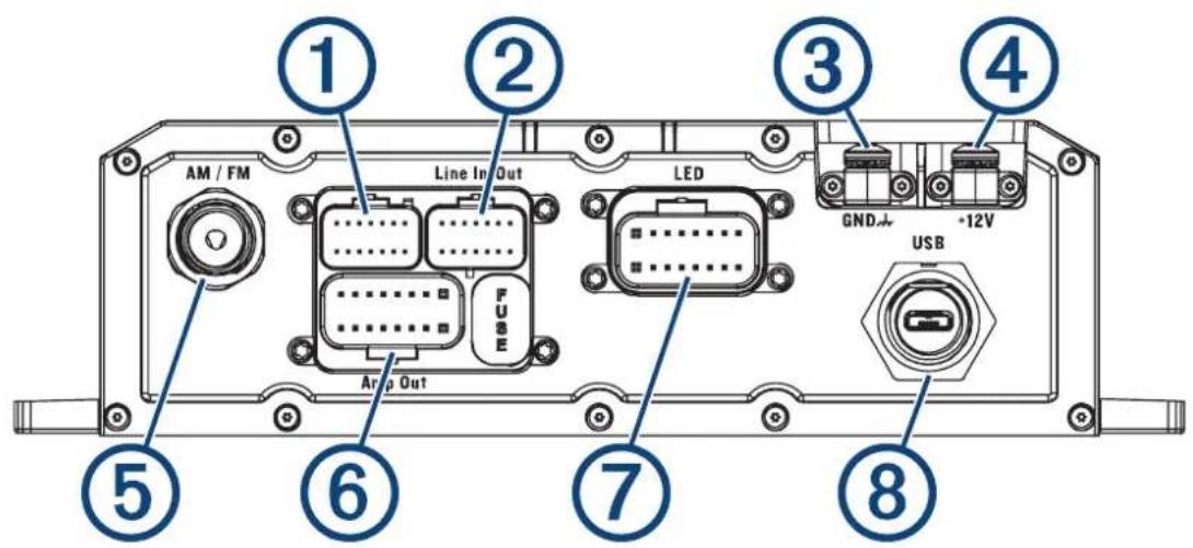
Connections
The stereo must be connected to power, to speakers, and to media input sources to function correctly. You should carefully plan the layout of the stereo, speakers, and your input sources before making any connections.
Identification de port
text_image
① AM / FM Line In Out LED ② FUSE Am p Out ③ GND -12V USB ④ ⑤ ⑥ ⑦ ⑧Élément Description
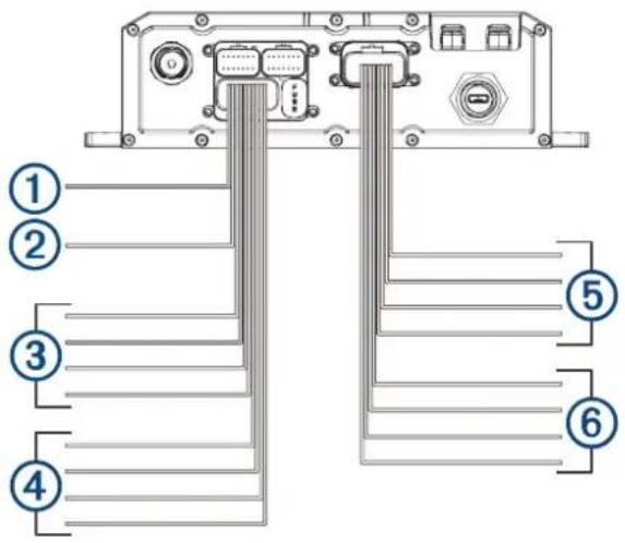
Speaker and LED Wiring Harness Wire and Connector Identification
text_image
① ② ③ ④ ⑤ ⑥| Wire Group Wire Color and Description | |
| 1 Ignition | Red: Connects to the vehicle accessory line. If the ignition wire is unused, ground the ignition wire or leave it disconnected. |
| 2 Amplifier on | Blue: Connects to an optional external amplifier to turn it on when the stereo turns on. |
| 3 Speaker zone 1 | White: Left (+), Connects to the included speaker. White with a black stripe: Left (-), Connects to the included speaker. Gray: Right (+), Connects to the included speaker. Gray with a black stripe: Right (-), Connects to the included speaker. |
| 4 Speaker zone 2 | Green: Left (+), Connects to an additional speaker. Green with a black stripe: Left (-), Connects to an additional speaker. Purple: Right (+), Connects to an additional speaker. Purple with a black stripe: Right (-), Connects to an additional speaker. |
| 5 LED RGB1 | Black: Power Red: Red LED Green: Green LED Blue: Blue LED |
| 6 LED RGB2 | Black: Power Red: Red LED Green: Green LED Blue: Blue LED |
Addressable LED Wiring Considerations
You can wire addressable LED lights to your Tread Audio Box. For more information, see the manual for your addressable LED lights.
Compatible addressable LED types:
- WS2812B
- WS2813
| Addressable LED LED Wire Color and Function | |
| Addressable LED 1 | Red: +5V PowerWhite: GroundGreen with a black stripe: Data |
| Addressable LED 2 | Red: +5V PowerWhite: GroundGreen with a black stripe: Data |
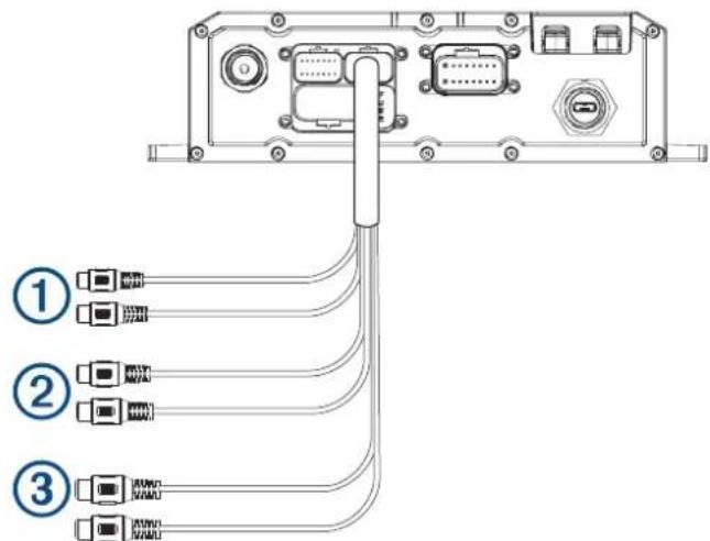
RCA Wiring Harness Wire and Connector Identification
text_image
Diagram showing three labeled connectors (①, ②, ③) connected to an electronic device interface with ports and cables.| Wire Number | Wire Function |
| 1 | Auxiliary in left: Provides a red and white RCA stereo line input for audio sources, such as a CD or MP3 player.Auxiliary in right: Provides a red and white RCA stereo line input for audio sources, such as a CD or MP3 player. |
| 2 | Line out left: Provides a full-range output to an external amplifier, and is associated with the volume control.Line out right: Provides a full-range output to an external amplifier, and is associated with the volume control.REMARQUE: if you are connecting to an external amplifier, you should use a ground loop isolator to ensure a clear signal. |
| 3 | Subwoofer out: Provides a single mono output to a powered subwoofer or subwoofer amplifier.REMARQUE: if you are connecting to an external amplifier, you should use a ground loop isolator to ensure a clear signal. |
text_image
Technical diagram of an electronic device rear panel with labeled components and directional arrow indicating assembly or connection.text_image
Diagram of a battery connected to a panel with labeled components including battery, switch, and terminal blocksUsing the Heat-Shrink Crimp Connectors
You should use the included heat-shrink crimp connectors to make a water-tight connection between the bare wires.
AVERTISSEMENT
Only use the heat gun to apply heat to the heat-shrink crimp connectors in a well-ventilated area. Do not use the heat gun near clothing or bare skin. Doing so can result in property damage or serious injury.
1 Using wire strippers, strip 6 mm ( ^1/_4 in.) off the end of each bare wire.
2 If necessary, twist the strands of each wire clockwise to bundle them together.

text_image
Diagram of a mechanical or electrical component with three labeled parts (1, 2, 3) and directional arrow indicating flow or movement.3 Insert one bare wire into one end of the heat-shrink crimp connector.②
The bare wires are not secure until they are crimped and sealed.
4 Insert the corresponding bare wire into the other end of the heat-shrink crimp connector.
5 Using pliers, crimp both sides of the center of the connector ③ secure the connection.
6 Using a heat gun, apply heat to the heat-shrink crimp connector until the connector is sealed to the wires. Do not apply heat to the wires directly.
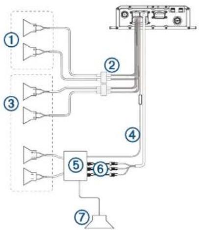
Complete System Wiring
This diagram illustrates a system installation with an external amplifier and subwoofer connected to the stereo using a line out.
REMARQUE : you can also connect speakers to the speaker wires for the internal stereo amplifier while using an external amplifier connected to the line out. Adjusting the volume affects speakers connected to the internal amplifier and speakers connected to the line out. This may result in uneven volume levels.
flowchart
graph TD
    A["Component 1"] --> B["Component 2"]
    C["Component 3"] --> B
    D["Component 4"] --> E["Component 5"]
    F["Component 6"] --> E
    G["Component 7"] --> H["Ground"]
| Item Description | |
| 1 | Zone 2 speakers |
| 2 | Water-tight connection |
| 3 | Zone 1 speakers |
| 4 | Amplifier-on signal wire |
| 5 | Powered amplifier |
| 6 | Line out and subwoofer out |
| 7 | Subwoofer |
text_image
Diagram showing cable connections between two devices with labeled components and connectors①
Speakers
②
Water-tight connection
text_image
Technical diagram of a mechanical device with numbered components for identificationtext_image
Technical diagram of a mechanical device with numbered components labeled 6, 7, and 8When connecting the speakers and LED lights to your stereo or amplifier, observe these considerations.
- You should use the included wire to connect the speakers to the stereo or amplifier. If necessary, you can use a larger gauge of wire (Wire Gauge Guide, page 75).
- You should make all of the wiring connections using the included heat-shrink crimp connectors. You should plan and select the best connection type for your installation needs.
- You can use this table to identify the polarity of the leads on the speaker.
| Lead color Polarity Use | ||
| White Positive (+) Speaker | ||
| White with a black stripe Negative (-) Speaker | ||
| Red Red LED | ||
| Green Green LED | ||
| Blue Blue LED | ||
| Black +12V Power | ||
Wire Gauge Guide
If necessary, you can use longer cables for your installation.
REMARQUE : if you are using aluminum or tinned wire, you should use a wire two gauges larger than the gauge listed below to compensate for a potential voltage drop due to the wire material.
- Use 16 AWG (1.31 mm ^2 ) for speaker wires.
- Use 20 AWG (0.52 mm ^2 ) for LED wires.
natural_image
Circular digital interface panel with playback controls and a 'FUSION' logo at bottom (no readable text or symbols beyond branding)
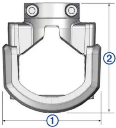
Bracket Side Dimensions
text_image
Technical diagram of a mechanical component with labeled parts ①, ②, and dimension lines① 85 mm ( 3^3/_8 in.)
② From 74 mm ( 2^7/8 in.) to 94 mm ( 3^11/16 in.)
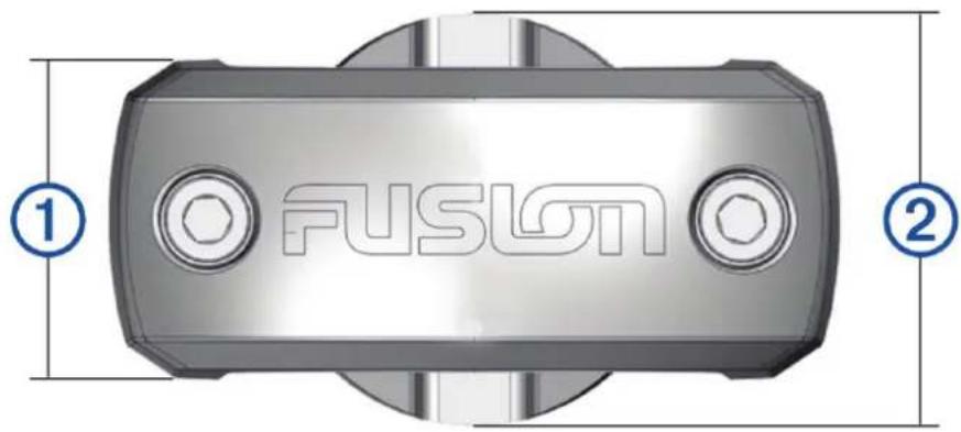
Bracket Top Dimensions
text_image
FUSIGN ① ②① 37 mm ( 1^7/_16 in.)
② 48 mm (2 in.)