
P910 1 D9 X - Cooker LA GERMANIA - Free user manual and instructions
Find the device manual for free P910 1 D9 X LA GERMANIA in PDF.
| Product type | Gas cooker (hob) |
| Brand | La Germania |
| Model | P910 1 D9 X |
| Category | Built-in hob |
| Dimensions (W x D) | 84 x 48 cm |
| Power supply | Gas (G20/G25/G30/G31) and electric 230 V |
| Number of burners | 5 |
| Burner types | Auxiliary, Semi-rapid, Rapid, Fish kettle, Ultra rapid |
| Ignition | Automatic electric with safety thermocouple |
| Nominal power (max) | 3.5 kW (ultra rapid burner) |
| Material | Stainless steel and enamel |
| Color | Stainless steel |
| Cleaning | Soapy water, no abrasive products |
| Safety | Thermocouple, automatic shut-off in case of flame out |
| Installation | Built-in, requires ventilation (min. opening 100 cm²) |
| Compliance | Gas directives 2009/142/EC, low voltage 2006/95/EC, EMC 2004/108/EC |
| Spare parts | Replacement nozzles, power cord, seals |
| Use | Domestic non-professional |
| Accessories included | Replacement nozzles, sealing gasket |
| Certification | CE |
Frequently Asked Questions - P910 1 D9 X LA GERMANIA
User questions about P910 1 D9 X LA GERMANIA
0 question about this device. Answer the ones you know or ask your own.
Ask a new question about this device
Download the instructions for your Cooker in PDF format for free! Find your manual P910 1 D9 X - LA GERMANIA and take your electronic device back in hand. On this page are published all the documents necessary for the use of your device. P910 1 D9 X by LA GERMANIA.
USER MANUAL P910 1 D9 X LA GERMANIA
(IT) ISTRUZIONI PER L'INSTALLAZIONE, MANUTENZIONE pagina. 2 ED USO DEI PIANI COTTURA DA INCASSO A GAS E MISTI 59X50 cm (TIPO P61/P61V) 74X50 cm (TIPO P71/P71V) 86X50 cm (TIPO P91/P91V)
(GB) INSTRUCTIONS FOR THE INSTALLATION, MAINTENANCE pag. 7 AND USE OF FIXED HOBS WITH GAS OR MIXED SUPPLY 59X50 cm (TYPE P61/P61V) 74X50 cm (TYPE P71/P71V) 86X50 cm (TYPE P91/P91V)
(FR) (BE) INSTRUCTIONS POUR L'INSTALLATION, L'ENTRETIEN ET page. 12 L'UTILISATION DES TABLES DE CUISSON ENCASTRABLES GAZ ET MIXTES 59X50 cm (MODELE P61/P61V) 74X50 cm (MODELE P71/P71V) 86X50 cm (MODELE P91/P91V)
These instructions are valid only for those countries which are indicated by their identification symbol on the front cover of the instruction booklet and on the label on the appliance.
The manufacturer cannot be held responsible for any damage to things or persons caused by an incorrect installation or by incorrect use of the appliance.
The manufacturer cannot be held responsible for any inaccuracies due to errors in printing or writing contained in this booklet. The appearance of the figures shown is also only approximate.
The manufacturer reserves the right to make changes to his products when it is considered necessary and useful without effecting the essential features regarding safety and function.
INDEX:
| TECHNICAL MANUAL FOR THE INSTALLER | pag. 7 |
| Inserting the hob | pag. 7 |
| Fixing the hob – Advice about installation | pag. 7-8 |
| Ventilation and airing of the premises – Connection to the gas supply | pag. 8 |
| Adaptation to different types of gas | pag. 8 |
| Regulation of the burners | pag. 8 |
| Connection to the electricity supply | pag. 8-9 |
| MAINTENANCE OF THE APPLIANCE – Replacing parts | pag. 9 |
| USE AND MAINTENANCE MANUAL | pag. 9 |
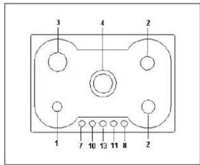
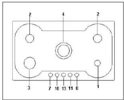
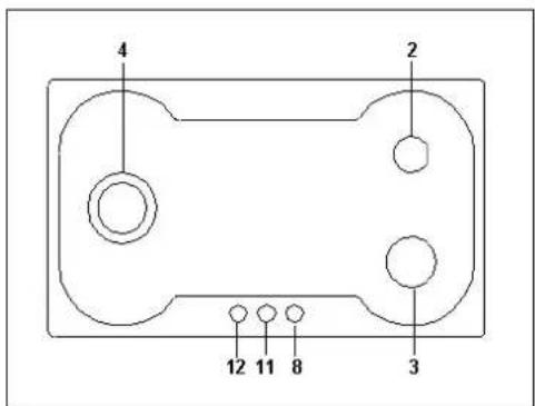
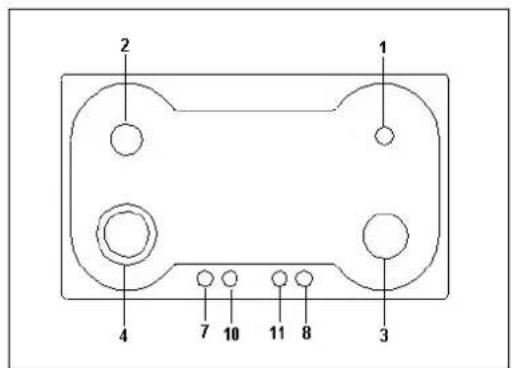
| Description of types of hobs | pag. 9 |
| Use of the burners | pag. 10 |
| Use of the electric plates | pag. 10 |
| Cleaning of the appliance | pag. 11 |
| Figures | pag. 37 |
| Electrical Diagram | pag. 39 |
THIS APPLIANCE HAS BEEN DESIGNED FOR NON PROFESSIONAL USE IN HOUSEHOLDS.
This appliance is marked according to the European directive 2012/19/EU on Waste Electrical and Electronic Equipment (WEEE). This guideline is the frame of a European-wide validity of return and recycling on Waste Electrical and Electronic Equipment.
TECHNICAL MANUAL FOR THE INSTALLER
INFORMATION FOR THE INSTALLER
The installation, all regulations, changes and maintenance referred to in this part must only be carried out by qualified staff. A wrong installation can cause damage to persons, animals or things which the manufacturer cannot be held responsible for. The safety and automatic regulation devices on the appliances can only ever be changed by the manufacturer or by the supplier which has been authorised to do so.
INSERTING THE HOB
When you have removed the various adjustable parts from their internal and external packaging, check that the hob is intact. If you are in doubt do not use the appliance and contact the qualified staff.
The parts which make up the packaging ( polystyrene, bags, boxes, nails etc.), are dangerous objects and must be kept out of children's reach.
Taking into consideration the specific dimensions of the appliance (see table N°1), make an opening in the work surface (see figure):
• Hobs type P61/P61V (59x50 cm) P71/P71V (74x50 cm) P91/P91V (86x50 cm) with right angle corner Fig. 1A.
• Hobs type P61/P61V (59x50 cm) P91/P91V (86x50 cm) with curved corner Fig. 1B
using the measurements indicated in table N°.1
The appliance must be classified in class 3 and thus it is subject to all the regulations indicated by the norms regarding these appliances.
Table N°.1
| Square Version | Rounded version | ||||
| W (cm) | D (cm) | W (cm) | D (cm) | R (cm) | |
| P61/P61V | 57 | 48 | 57 | 48 | 13.5 |
| P71/P61V | 57 | 48 | |||
| P91/P91V | 84 | 48 | 84 | 48 | 13.5 |
| L1 min (cm) | 6 |
| L2 min (cm) | 4 |
| L3 min (cm) | 10 |
| L4 min (cm) | 70 |
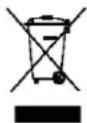
FIXING THE HOB
In order to prevent liquids from accidentally leaking into the kitchen unit underneath the appliance is equipped with a special seal. To put on this seal follow the instructions below very carefully.
1) Stretch out the seal along the edge of the opening, taking care to overlap the joining points. (fig. 2).
2) Insert the hob into the opening in the kitchen unit.
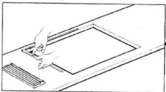
3) With a screwdriver assemble the 4 plates A with the special screw B (fig. 3).
4) Move the plates along and fix them using screw B.
5) Reinsert the part of the seal on the outside of the hob.
IMPORTANT INFORMATION CONCERNING THE INSTALLATION OF THE APPLIANCE
The hob can be installed by itself, in an isolated position or inserted between two kitchen units or between one kitchen unit and a wall. Furthermore the back wall and surrounding surfaces must resist a temperature of 65 K.
To prevent the plastic layer which covers the kitchen unit from ungluing, the glue used to join the two surfaces together must resist temperatures of up to 150 °C
The installation of the appliance must be carried out according to the norms in force of the country concerned and the appliance must be installed in a well ventilated place.
This appliance is not equipped with devices to remove the products of combustion. The appliance must therefore be connected following the norms for installation mentioned above. Special attention must be paid to the information below regarding aeration and ventilation of the premises.
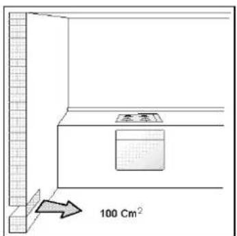
VENTILATION OF THE PREMISES
To guarantee that the appliance works correctly it is necessary that the place where the appliance is installed is continuously ventilated. The volume of the premises must not be less than 25 m^3 and the quantity of air needed must be based on the regular combustion of gas and on the ventilation of the premises. The natural flow of air will take place through permanent openings made in the wall of the premises to be ventilated: these openings will be connected to the outside and must have a minimum section of 100 cm^2 (see Fig. 4). These openings must be made in such a way that they cannot be obstructed.
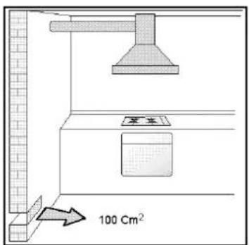
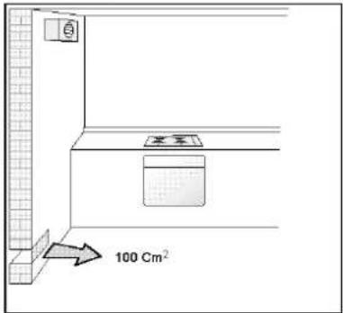
POSITION AND VENTILATION
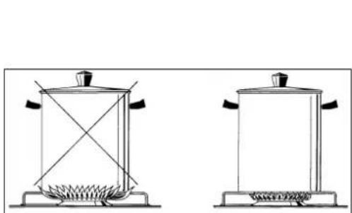
The cooking appliances that use gas must always remove the products of combustion via a hood linked to chimneys, chimney flues or via a direct connection to the outside (see Fig. 5A). If it is not possible to fit a hood it is possible to use a fan, fitted on the window or facing directly outside, which operates when the appliance is in use. (see Fig. 5B). In this way the norms in force of the country concerned regarding the ventilation of premises are strictly followed.
CONNECTING THE APPLIANCE TO THE GAS SUPPLY
Before connecting the appliance to the gas supply you first need to remove the plastic protective plug for the gas supply which is inserted under pressure in the gas inlet connection. To remove the plug simply unscrew it.
Then make sure that the details shown on the label on the lower part of the case are compatible with those of the gas supply. A label on the last page of this manual and on the lower part of the case indicates the conditions for regulating the appliance: type of gas and pressure used.
IMPORTANT: This appliance must be installed in accordance with the norms in force of the country concerned and it must only be used in a well-ventilated place.
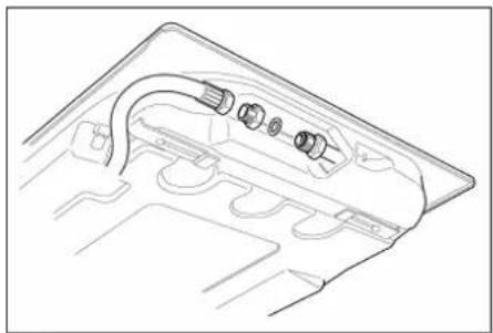
ATTENTION: Remember that the gas inlet connection for the appliance is threaded 1/2 gas cylindrical male in accordance with the norms UNI-ISO 228-1. (Fig. 6)
ADAPTING TO DIFFERENT TYPES OF GAS
Before carrying out any maintenance work, disconnect the appliance from the gas and electric supply.
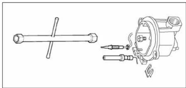
- CHANGING THE NOZZLES FOR USE WITH OTHER TYPES OF GAS:
To change the nozzles of the burners use the following procedure:
Lift up the burners and unscrew the nozzles (Fig. 7) using an adjustable spanner of 7 mm and change the nozzles with those designed for the new gas supply according to the information given in TABLE N° 2 shown below.
ATTENTION: After carrying out the changes described above, the technician must put the label corresponding to the new gas supply on the appliance to take the place of the old label. This label is found in the bag containing spare nozzles.
TABLE N°2: Adapting to different types of gas
APPLIANCE CATEGORY: II2H3+
| Burner | Type of Gas | Pressure | Nozzle diameter | Nominal Charge | Reduced Charge | Diameter by-pass 1/100mm | |||||
| mbar | 1/100mm | g/h | l/h | Kw | kcal/h | kw | kcal/h | No saf. | safety | ||
| Auxiliary | Natural G20 | 20 | 72 | - | 95 | 1 | 860 | 0,3 | 258 | 27 | 27 |
| Butane G30 | 28 | 50 | 73 | - | 1 | 860 | 0,3 | 258 | 27 | 27 | |
| Propane G31 | 37 | 50 | 71 | - | 1 | 860 | 0,3 | 258 | 27 | 27 | |
| Semi-Rapid | Natural G20 | 20 | 97 | - | 167 | 1,75 | 1505 | 0,44 | 378 | 34 | 31 |
| Butane G30 | 28 | 65 | 127 | - | 1,75 | 1505 | 0,44 | 378 | 34 | 31 | |
| Propane G31 | 37 | 65 | 125 | - | 1,75 | 1505 | 0,44 | 378 | 34 | 31 | |
| Rapid | Natural G20 | 20 | 115 | - | 286 | 3 | 2580 | 0,75 | 645 | 44 | 42 |
| Butane G30 | 28 | 85 | 218 | - | 3 | 2580 | 0,75 | 645 | 44 | 42 | |
| Propane G31 | 37 | 85 | 214 | - | 3 | 2580 | 0,75 | 645 | 44 | 42 | |
| Fish | Natural G20 | 20 | 120 | - | 276 | 2,9 | 2494 | 1,4 | 1204 | 65 | 60 |
| Butane G30 | 28 | 85 | 211 | - | 2,9 | 2494 | 1,4 | 1204 | 65 | 60 | |
| Propane G31 | 37 | 85 | 207 | - | 2,9 | 2494 | 1,4 | 1204 | 65 | 60 | |
| Ultra Rapid | Natural G20 | 20 | 135 | - | 334 | 3.5 | 3010 | 1.8 | 1548 | 70 | 70 |
| Butane G30 | 28 | 95 | 254 | - | 3.5 | 3010 | 1.8 | 1548 | 70 | 70 | |
| Propane G31 | 37 | 95 | 250 | - | 3.5 | 3010 | 1.8 | 1548 | 70 | 70 | |
REGULATION OF BURNERS:
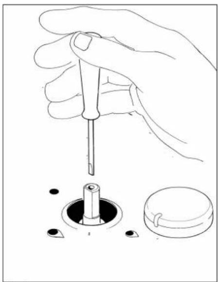
1) Regulation of the "MINIMUM" on the burners
To regulate the minimum on the burners carry out the following procedure indicated below:
1) Turn on the burner and put the knob onto position MINIMUM (small flame).
2) Remove the knob (Fig. 8) of the tap which is set for standard pressure. The knob is found on the bar of the tap itself.
3) Beside the tap bar on the work top, use a small screwdriver that fits the screw (gold) found on the lower part of the tap (Fig. 8) and turn the fixing screw to the right or left until the flame of the burner is regulated in the most suitable way to MINIMUM.
4) Make sure that the flame does not go out when changing the position quickly from MAXIMUM to the MINIMUM position.
ATTENTION: The regulation described above can be carried out only with burners using methane gas and city gas (where available), while with burners using liquid gas the screw must be fully screwed in, in a clockwise direction.
CONNECTION OF THE APPLIANCE TO THE ELECTRICITY SUPPLY:
Connection to the electricity supply must be carried out according to the norms and indications of the law in force.
Before carrying out the connection check that:
- The electric charge of the system and the sockets are suitable for the maximum power of the appliance (see label on the lower part of the case).
- The socket or system is equipped with an efficient earth connection according to the norms and indications of the law currently in force. No responsibility can be held if these indications are not respected.
When the connection to the electricity supply is made with a socket.
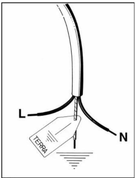
Fit onto the electric cable a standard plug (if it is not provided) which is appropriate for the charge indicated on the label. Connect up the wires according to the diagram in Fig. 9 taking care to respect the corresponding pairs listed below:
letter L (phase) = brown coloured wire;
letter N (neutral) = blue coloured wire;
symbol" 1- earth = green-yellow coloured wire;
- The electric cable must be positioned so that it cannot reach a temperature of over 75 K at any point.
- Do not use reducers, adapters or shunts for the connection as they could cause false contacts and subsequent dangerous overheating.
When the connection is made directly with the electricity supply: - Place a single-pole switch between the appliance and the electricity supply. The switch must be of a suitable charge for the appliance with a minimum opening between the contacts of 3 mm.
- Remember that the earth wire must not be interrupted by the switch.
- Alternatively the electrical connection can also be protected by a differential switch of high sensitivity.
- You are strongly advised to fix the special yellow-green earth wire to an efficient earthing system
ATTENTION: The appliance conforms with the regulations of directives 2009/142/CE (Gas Directive) regarding gas appliances for domestic use and the like2006/95/CE (Low Voltage Directive) regarding electrical safety and 2004/108/CE (EMC Directive) regarding electromagnetic compatibility.
Before carrying out any maintenance work, disconnect the appliance from the gas and electric supply.
To replace different components such as burners, taps and electrical parts you must take out the hob from the kitchen unit by releasing the fixing hooks, unscrew the fixing screws of the burners on the work top, unscrew the fixing nuts of the electric plates which are visible on the lower part of the hob and remove the worktop in order to carry out the replacement of the defective parts.
NOTE: If the taps need replacing you also need to unscrew the two fixing screws of the gas ramp at the bottom of the hob which are found on the upper part of the latter.
For appliances equipped with automatic "ON" switches you must dismantle the "ON" switch chain before replacing the taps.
You are advised to change the seal on the tap every time you replace a tap in order to ensure a perfect hold between the body and ramp.
WARNING: The electric cable which is provided with the appliance is connected to the appliance with a type X connection and thus can be replaced with the same type of cable as that installed without using special tools.
In the event of wear or damage to the mains cable, replace it following the indications shown below in table n°3:
TABLE N° 3: Types and sections of the electric mains cable for hobs
| Dimensions of hob | Type of hob | Type/ section of mains cable |
| 59 x 50 cm.74 x 50 cm.86 x 50 cm. | gas burners | H05VV-F 3x0,75 mm2 |
| gas burners + 1 electric plate. | H05VV-F 3x1 mm2 |
WARNING: If you replace the electric mains cable the installer must have the earth conductor about 2 cm longer than the phase conductors and must also take heed of the warnings regarding electric connection.
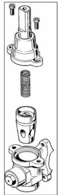
Oiling the taps: (This must be carried out by qualified staff from a technical assistance centre)
If a tap becomes difficult to move you must oil the tap, without delay, following the instructions given below:
1) Dismantle the main part of the tap by unscrewing the two screws that can be found on the bar of the tap itself. (Fig. 10)
2) Take out and clean the holding cone and its setting with a cloth soaked in diluent.
3) Oil the cone lightly with the special oil.
4) Insert the cone, move it a few times, take it out again, remove the excess oil and make sure that the areas where the gas flows are not obstructed.
5) Reassemble all the pieces in the reverse order to that followed for the dismantling and check that the tap is working properly.
USE AND MAINTENANCE MANUAL
DESCRIPTION OF HOBS
On the control panel above every knob there is a diagram which indicates which burner the knob in question refers to. The burners can be turned on in several ways according to the type of appliance and its individual features:
- Manual “On” switch (this is always possible even if the electric current is cut off): Turn the knob corresponding to the selected burner in an anticlockwise direction so that the knob is at MAXIMUM (this corresponds to a large flame) and then put a lit match to the burner.
- Electric "On" switch: Turn the knob corresponding to the selected burner in an anticlockwise direction so that the knob is at MAXIMUM (this corresponds to a large flame) and then press the lighter button and let it go as soon as the burner is alight..
- Automatic Electric “On” switch: Turn the knob corresponding to the selected burner in an anticlockwise direction so that the knob is at MAXIMUM (this corresponds to a large flame) and then press in the knob. Let it go as soon as the burner is alight.
- “On “ switch for burners with safety device ( thermocouples ): Turn the knob corresponding to the selected burner in an anticlockwise direction so that the knob is at MAXIMUM (this corresponds to a large flame) and then use one of the lighting devices described above. When the burner is lit keep the knob pressed in for about 10 seconds in order to allow the flame to heat up the thermocouple. If the burner goes out when letting the knob go, repeat the operation all over again.
N.B.: You are advised not to try and light a burner if its flame divider is not correctly in place.
Advice for the best use of the burners:
- Use suitable pans for each burner (see tab. n° 4 and Fig. 12).
- When boiling point is reached turn the knob on to MINIMUM.
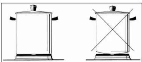
- Always use pans with a lid.
TABLE N°4: Recommended pan diameters.
| BURNER | PAN DIAMETERS recommended (cm.) |
| Auxiliary | 12 - 14 |
| Semi-rapid | 14 - 26 |
| Rapid | 18 - 26 |
| Double crown | 22 - 26 |
ATTENTION: use containers with a flat bottom
ATTENTION: If there is no electric current you can light the burners with matches.
Lighting the burners with safety thermocouples can only be carried out when the knob is on MAXIMUM (large flame). When cooking food with oil or fat which can easily set alight, the user must not leave the appliance.
Do not use sprays near the appliance when it is in use. When using the burners make sure that the pan handles are in the correct position. Keep children away. If the hob has a lid, before closing it, make sure that the surrounding work surface is cleaned of any food that has been left there.
NOTE: The use of a gas cooking appliance produces heat and humidity in the place where it is installed. Therefore you need to ensure that the place is well ventilated, keeping clear the natural ventilation openings (Fig. 4) and using the mechanical ventilation device/flue or electric fan (Fig. 5A and 5B). Intensive or prolonged use of the appliance may require additional ventilation such as by opening a window or an increased ventilation efficiency obtained by increasing the power of the echanical ventilators if it is present.
USE OF THE ELECTRIC PLATES
The plates are controlled by a switch with 6 positions (Fig. 13).
The plates can be inserted by rotating the knob onto the desired position. On the front of the appliance there is a design showing which plate the knob refers to. The insertion of the plate is shown by the indicator light which is also found on the front panel of the appliance.
How to use an electric plate:
When you use the plate for the first time or after a long period over which the plate has not been used, you are advised to use the plate on position 1 for about 30 minutes in order to eliminate any humidity absorbed by the isolating material inside. As an indication we give a table with the necessary rules to follow for the best use of the electric plates.
WARNING: When using the plate for the first time or after a long period over which the plate has not been used, in order to eliminate any humidity absorbed by the isolating material it is necessary to use the plate for about 30 minutes on position 1 of the switch.
| PLATE 1500W | Watt | COOKING POSSIBILITIES |
| 0 | 0 | Plate switched off |
| 1 | 135 | To melt butter, chocolate etc. - To heat up small quantities of liquid |
| 2 | 165 | To heat up larger quantities of liquid - to prepare creams/sauces with long cooking times |
| 3 | 250 | To thaw foods, cooking boiling temperatures |
| 4 | 500 | To cook roasts of delicate meat and fish |
| 5 | 750 | For roast of chops and steaks, for large boiled foods |
| 6 | 1500 | To boil large quantities of water, to fry |
For a correct use remember the following:
- Dry the bottom of the pan before putting it on the plate.
- Use pans with a flat bottom and in thick metal (see Fig. 14).
- Never use pans which are smaller than the plate.
- Switch on the current after you have put the pan on the plate.
- After use, to keep the plate in good condition, always treat the plate with normal products for electric plates which are available on the market so that the surface is always clean; doing this will avoid any eventual oxidisation (rust).
- Even after use the plates stay hot for a long time and so do not put your hands or other objects on the plates so as to prevent possible burns.
- When the plates are in use make sure that the pan handles are positioned correctly. Keep children away. – When cooking foods with oil and fat, which can easily set alight, the user must not leave the appliance.
WARNING: As soon as you see a crack in the surface of the plate immediately disconnect the appliance from the mains.
CLEANING OF THE APPLIANCE
Before carrying out any cleaning operation disconnect the appliance from the electric mains and turn off the main tap which supplies the appliance with gas.
Cleaning the worktop: Periodically the burner heads, enamelled steel grills, enamelled lids and flame dividers must be cleaned with warm soapy water, rinsed and dried well.
Any liquid which overflows from the pan must always be removed with a cloth.
If opening or closing any tap is difficult do not force it but ask for an urgent check from the technical assistant.
Cleaning of the enamelled parts: To maintain the features of the enamelled parts they must be cleaned frequently with soapy water. Never use abrasive powders. Avoid leaving acid or alkaline substances on the enamelled parts (vinegar, lemon juice, salt, tomato juice etc.) and washing the enamelled parts when they are still warm.
Cleaning of the stainless steel parts: Clean the parts with soapy water and then dry them with a soft cloth. The shininess is maintained by periodically cleaning with the special products normally available on the market. Never use abrasive powders.
Cleaning of the burner flame dividers: as they are not fixed, the flame dividers can be cleaned by simply removing them and cleaning with soapy water. After drying them well and checking that the holes are not blocked, put them back into their correct position.
(FR) (BE)
LISEZ ATTENTIVEMENT CETTE NOTICE AVANT D'INSTALLER ET D'UTILISER L'APPAREIL.
INSTALLATIE VAN HET APPARAAT
text_image
L1 R D W L2 L4 L3Fig.1B
natural_image
Line drawing of a hand pressing down on a rectangular object with a gridded base (no text or symbols)Fig.2
text_image
Technical diagram showing mechanical assembly with labeled components A and B, including a rotating shaft and directional arrow.Fig.3
text_image
100 Cm²Fig.4
text_image
100 Cm²Fig.5A
text_image
100 Cm²Fig.5B
natural_image
Technical line drawing of a mechanical component with no visible text or symbolsFig.6
natural_image
Technical line drawing of a mechanical assembly with two components: a cylindrical rod and a motor (no text or symbols)Fig.7
natural_image
Illustration of a hand using a screwdriver to adjust a circular component with holes (no text or symbols)Fig. 8
text_image
L N TERRAFig.9
natural_image
Technical line drawings of mechanical components including a cylindrical spring, piston, and housing (no text or labels)Fig.10
text_image
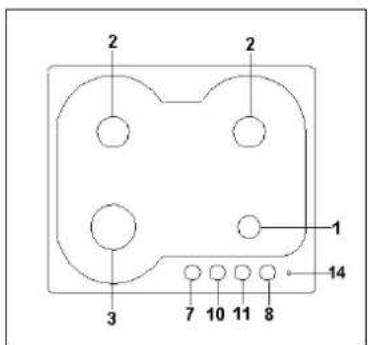
2 2 1 14 3 7 10 11 8Fig.11A
text_image
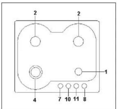
2 2 1 4 7 10 11 8Fig.11B
text_image
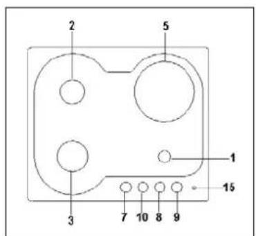
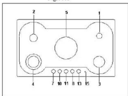
2 5 1 3 7 10 8 9 15Fig.11C
text_image
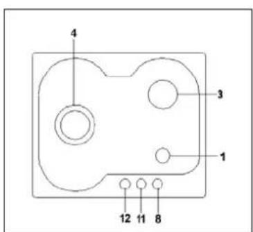
4 3 1 12 11 8Fig.11D
text_image
3 4 2 1 7 10 13 11 8 2Fig. 11E
text_image
2 4 2 3 7 10 13 11 8 1Fig.11F
text_image
4 2 12 11 8 3Fig.11G
text_image
2 1 4 7 10 11 8 3Fig.11H
text_image
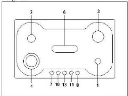
2 6 3 4 7 10 13 11 8 1Fig.11L
text_image
2 5 1 4 7 10 11 8 13 15 3Fig.11M
text_image
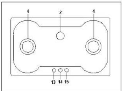
4 2 4 13 14 15Fig.11N
natural_image
Two simple line drawings of a portable stove with heating elements, no text or symbols present.Fig.12

text_image
0 1 θ 2 5 3 4Fig. 13
natural_image
Two identical line drawings of a cooking pot with handles, shown from different angles (no text or symbols)Fig. 14
Targhetta portadati
CE
Targhetta gas collaudo