PZ0023 - Sensor IFM - Free user manual and instructions
Find the device manual for free PZ0023 IFM in PDF.


| Product type | Electronic pressure sensor |
| Brand | IFM |
| Model | PZ0023 (PB5 series) |
| Main function | Pressure detection with N.O./N.C. switching output and LED bar graph display |
| Supply voltage | 18 ... 30 V DC |
| Power consumption | ≤ 50 mA |
| Output current | 250 mA max |
| Electrical protection | Short-circuit, reverse polarity, overload protection |
| Measuring range (depending on variant) | 0,05 ... 400 bar (depending on PB5xx code) |
| Display | Bar graph of 10 green LEDs (pressure) + 1 yellow LED (switching status) |
| Adjustment | High (S) and low (R) set points via SET and ENTER buttons |
| Hysteresis | Adjustable via gap between S and R |
| Materials in contact with fluid | Stainless steel 303, ceramic, FPM (Viton) |
| Housing material | EEPDM/X (Santoprene), FPM, NBR, PA, Pocan, PC, Stainless steel 304 |
| Protection rating | IP 65 or IP 67 depending on variant |
| Ambient temperature | -25 ... +80 °C |
| Fluid temperature | -25 ... +80 °C |
| Electrical connection | M12 connector (PNP/NPN/SSDC) |
| Mounting | Via suitable process connection (see label "Port Size") |
| Programming lock | Possible by long press (10s) on both buttons |
| Maintenance | No specific maintenance required; clean the exterior with a dry cloth |
Frequently Asked Questions - PZ0023 IFM
User questions about PZ0023 IFM
0 question about this device. Answer the ones you know or ask your own.
Ask a new question about this device
Download the instructions for your Sensor in PDF format for free! Find your manual PZ0023 - IFM and take your electronic device back in hand. On this page are published all the documents necessary for the use of your device. PZ0023 by IFM.
USER MANUAL PZ0023 IFM
Electronic pressure sensor
natural_image
Simple line drawing of a cylindrical device with two circular ports and a base (no text or symbols)Controls and visual indication
![1 2 OUT 10 20 30 40 50 60 70 80 90 100 SET S ENTER R SET R ENTER S [bar] ③ ④](/content/2026/04/604519/images/7a0d91b438cc3dae319996dc80e859d3f77fb28b4803d299aed7f5537e0736f5.jpg)
| 1 | LEDs green | display of the system pressure (lit LEDs, and of the switch-on point (flashing LED,)) |
| 2 | LED yellow | switching status;lights if the output has switched |
| 3 | SET S / ENTER R button | indication and adjustment of the switch-on point (S); acknowledgement of the switch-off point (R)* |
| 4 | SET R / ENTER S button | indication and adjustment of the switch-off point (R); acknowledgement of the switch-on point (S)* |
*Setting: scrolling by holding pressed; incremental by pressing briefly
Contents
Safety instructions . . . . . . . . . . . . . . . . page 12
- Function and features ..... page 12
- Operating modes . . . . . . . . . . . . . . . . . . page 14
- Installation . . . . . . . . . . . . . . . . . . . . . . . . page 15
- Electrical connection ..... page 15
- Programming ..... page 16
- Commissioning / Operation ..... page 17
- Technical data ..... page 17 Scale drawing ..... page 26
Menu structure

flowchart
graph TD
    A["Run Mode 10-100 OUT"] --> B["1x"]
    B --> C["display of switch-on point (S) (in 1% steps)"]
    C --> D["5s"]
    A --> E["1x"]
    E --> F["display of switch-off point (R) (in 1% steps)"]
    F --> G["5s"]
    A --> H[">5s"]
    H --> I["setting of switch-on point (S)"]
    I --> J["1x"]
    A --> K[">5s"]
    K --> L["setting of switch-off point (R)"]
    L --> M["1x"]
    style A fill:#f9f,stroke:#333
    style B fill:#ccf,stroke:#333
    style C fill:#cfc,stroke:#333
    style D fill:#fcc,stroke:#333
    style E fill:#cff,stroke:#333
    style F fill:#ffc,stroke:#333
    style G fill:#cfc,stroke:#333
    style H fill:#ccf,stroke:#333
    style I fill:#cfc,stroke:#333
    style J fill:#fcc,stroke:#333
    style K fill:#cff,stroke:#333
    style L fill:#ffc,stroke:#333
    style M fill:#cfc,stroke:#333
| Display of S / R in 1% steps)= value of the lit LED (☐)+ 1/10 of the value of the flashingLED (≡≡) | PBxxx30 ... 25 bar | 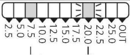 7,5bar + 2bar = 9,5bar 7,5bar + 2bar = 9,5bar | |
| PBxxx00 ... 400 bar | 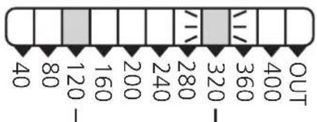 120bar + 32bar = 152bar 120bar + 32bar = 152bar | PBxxx40 ... 10 bar | 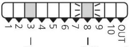 3bar + 0,8bar = 3,8bar 3bar + 0,8bar = 3,8bar |
| PBxxx10 ... 250 bar | 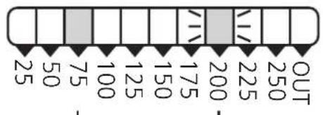 75bar + 20bar = 95bar 75bar + 20bar = 95bar | PBxxx60 ... 2,5 bar |  0,75bar + 0,2bar = 0,95bar 0,75bar + 0,2bar = 0,95bar |
| PBxxx20 ... 100 bar | 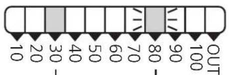 30bar + 8bar = 38bar 30bar + 8bar = 38bar | PBxxx70 ... 1 bar | OUT0,3bar + 0,08bar = 0,38bar |
Safety instructions
Please read the product description prior to installing the unit. Please check that the product is suitable for your application without any restrictions.
If the operating instructions or the technical data are not adhered to, personal injury and/or damage to property may occur.
Please check in all applications that the product materials (see Technical data) are compatible with the media to be measured.
For gaseous media the application is limited to max. 25 bar.
1. Function and features
The pressure sensor detects whether a preset value has been reached or not and indicates this by a switched signal.
In addition a row of LEDs signals the current system pressure and the switch point (both in 10% steps).

□ = lit LED
= flashing LED
Applications (type of pressure: relative pressure):
| Measuring range | Order no.overl. pressure | Bursting pressure | |
| PB5xx0 0 ... | 400 bar 600 bar 100 | bar | |
| PB5xx1 0 ... | 250 bar 400 bar 850 | bar | |
| PB5xx2 0 ... | 100 bar 300 bar 650 | bar | |
| PB5xx3 0 ... | 25 bar 100 bar 350 | bar | |
| PB5xx4 0 ... | 10 bar 50 bar 150 | bar | |
| PB5xx6 0 ... | 2,5 bar 20 bar 50 | bar | |
| PB5xx7 0 ... | 1 bar 10 | bar 30 bar |

Avoid static and dynamic overpressure exceeding the given overload pressure.
Even if the bursting pressure is exceeded only for a short time the unit can be destroyed (danger of injuries)!

Indication of the current system pressure as from 5% of the value of the measuring range. “All LEDs OUT” does not mean that the system is free of pressure!
The unit
- can be used as N.O. or N.C.
• and operates with the hysteresis function.
When the system pressure is rising, the output switches when the switch-on point has been reached (S); when the system pressure is falling again, the output switches back when the switch-off point (R) has been reached.
The hysteresis can be set: First the switch-on point is set, then the switch-off point with the requested difference.

line
| t | P | | ---- | ----- | | 0 | 0 | | 1 | 1 | | 2 | 1 | | 3 | 1 | | 4 | 1 | | 5 | 1 | | 6 | 1 | | 7 | 1 | | 8 | 1 | | 9 | 1 | | 10 | 1 | | 11 | 1 | | 12 | 1 | | 13 | 1 | | 14 | 1 | | 15 | 1 | | 16 | 1 | | 17 | 1 | | 18 | 1 | | 19 | 1 | | 20 | 1 | | 21 | 1 | | 22 | 1 | | 23 | 1 | | 24 | 1 | | 25 | 1 | | 26 | 1 | | 27 | 1 | | 28 | 1 | | 29 | 1 | | 30 | 1 | | 31 | 1 | | 32 | 1 | | 33 | 1 | | 34 | 1 | | 35 | 1 | | 36 | 1 | | 37 | 1 | | 38 | 1 | | 39 | 1 | | 40 | 1 | | 41 | 1 | | 42 | 1 | | 43 | 1 | | 44 | 1 | | 45 | 1 | | 46 | 1 | | 47 | 1 | | 48 | 1 | | 49 | 1 | | 50 | 1 | | 51 | 1 | | 52 | 1 | | 53 | 1 | | 54 | 1 | | 55 | 1 | | 56 | 1 | | 57 | 1 | | 58 | 1 | | 59 | 1 | | 60 | 1 | | 61 | 1 | | 62 | 1 | | 63 | 1 | | 64 | 1 | | 65 | 1 | | 66 | 1 | | 67 | 1 | | 68 | 1 | | 69 | 1 | | 70 | 1 | | 71 | 1 | | 72 | 1 | | 73 | 1 | | 74 | 1 | | 75 | 1 | | 76 | 1 | | 77 | 1 | | 78 | 1 | | 79 | 1 | | 80 | 1 | | 81 | 1 | | 82 | 1 | | 83 | 1 | | 84 | 1 | | 85 | 1 | | 86 | 1 | | 87 | 1 | | 88 | 1 | | 89 | 1 | | 90 | 1 | | 91 | 1 | | 92 | 1 | | 93 | 1 | | 94 | 1 | | 95 | 1 | | 96 | 1 | | 97 | 1 | | 98 | 1 | | 99 | 1 | | Note: The data is extracted from the image and displayed in the code as it is a schematic representation. The diagram contains labels for the x-axis 't' and y-axis 'P'. The text 'N.O.' and 'N.C.' are not present in the diagram.Setting range:
| Switch-on point (S) | Switch-off point (R) | in steps ofOrde | |
| PB5xx0 20 ... 400 bar 12 ... 392 | bar 4 bar | ||
| PB5xx1 | 12.5 ... 250 bar 7.5 ... 245 bar 2,5 bar | ||
| PB5xx2 | 5 ... 100 bar 3 ... 98 bar 1 bar | ||
| PB5xx3 | 1.25 ... 25 bar 0.75 ... 24.5 bar 0.25 bar | ||
| PB5xx4 | 0.5 ... 10 bar 0.3 ... 9.8 bar 0.1 bar | ||
| PB5xx6 | 0.125 ... 2.5 bar 0.075 ... 2.45 bar | 0.025 bar | |
| PB5xx7 | 0.05 ... 1.0 bar | 0.03 ... 0.98 bar 0.01 bar |
2. Operating modes
The unit has the following operating modes:
Run mode (normal operating mode), display mode (indication of the switch-on / switch-off point), programming mode (setting of the switch-on / switch-off point).
Run mode:
When the supply voltage has been applied, the unit is in the Run mode. It monitors and switches the transistor output according to the set hysteresis.
The green LEDs indicate the current system pressure, the yellow LED indicates the switching state of the output.
Display mode:
When the button “SET S” (or “SET R”) is pressed for a short time, the unit passes to the Display mode. Internally it remains in the operating mode. Irrespective of this the switch-on / switch-off point can be read in 1% steps.
- When the button is pressed for a short time, the corresponding value is displayed for approx. 5s; then the unit returns to the Run mode.


Programming mode:
The unit passes to the programming mode when after the selection of a parameter value (Display mode) the "Set" button is pressed until the display of the parameter value is changed. Internally the unit remains in the operating mode. It continues its monitoring function with the existing parameters until the change has been terminated.
You can change the parameter value by pressing the "Set" button and confirm it by pressing the "Mode/Enter" button. The unit returns to the Run mode when no button has been pressed for 5s.
3. Installation

Before mounting and removing the sensor, make sure that no pressure is applied to the system.
Mount the pressure sensor on a suitable process connection (see type label "Port Size").
4. Electrical connection

The unit must only be connected by an electrician.
The national and international regulations for the installation of electrical equipment must be observed.
Voltage supply to EN50178, SELV, PELV.
Disconnect power before connecting the unit.
Wiring:
| M12 connector DC PNP | 1 BN L+ 4 BK 3 BU L- L- | 3 BU L+ 4 BK 1 BN L- L- |
| M12 connector DC NPN | 1 BN L+ 4 BK 3 BU L- L- | 3 BU L+ 4 BK 1 BN L- L- |
| SS connector DC PNP | 1 L+ 3 2 L- L- | 2 L+ 3 1 L- |
Core colours of ifm sockets:
1 = BN (brown), 2 = WH (white), 3 = BU (blue), 4 = BK (black).
5. Programming
Increase the switch-on point / switch-off point
| 1 | 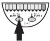 Press the SET S-button* and keep it pressed until the requested switch point is displayed.As soon as the LED starts moving the switch point can be increased (incremental by pressing briefly or scrolling by holding pressed). Press the SET S-button* and keep it pressed until the requested switch point is displayed.As soon as the LED starts moving the switch point can be increased (incremental by pressing briefly or scrolling by holding pressed). | 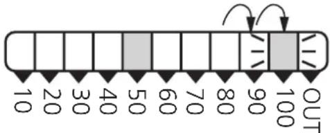 After 5s the flashing LED moves from left to right. After 5s the flashing LED moves from left to right.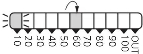 fter LED 9 has been reached the cycle starts again at LED 0. The LED which is constantly lit moves on by one position.** fter LED 9 has been reached the cycle starts again at LED 0. The LED which is constantly lit moves on by one position.** | |
| 2 | 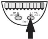 Press the ENTER S-button* briefly (acknowledgement). Press the ENTER S-button* briefly (acknowledgement). | The set switch point becomes effective; the unit passes into the operating mode. |
* SET R button to set the switch-off point
ENTER R button to acknowledge the setting of the switch-off point
The switch-on point (S) is always higher than the switch-off point (R). The unit does not accept values for R which are higher than S.
**Overflow: If the flashing LED and the lit LED exceed the maximum setting value, the cycle starts again at the minimum setting value.
Decrease the switch-on point / switch-off point
Let the flashing and lit LEDs move to the maximum setting value. Then the cycle starts again at the minimum setting value.
Locking / Unlocking
The unit can be electronically locked to prevent unwanted adjustment of the set parameters: Press both pushbuttons for 10s. Indication goes out briefly (acknowledgement of locking / unlocking). Units are delivered from the factory in the unlocked state.
6. Commissioning / Operation
After mounting, wiring and setting check whether the unit operates correctly. Faults displayed during operation: All LEDs flashing in case of short-circuit.
- Technical data
| Operating voltage [V] . . . . . . . . . . . . . . . . . . . . . . . . . . . . . . . . . . . . . . . . . . . . . . . . . . . . . . . . . . . . . . . . . . . . . . . . . . . . . . . . . . . . . . . . . . . . . . . . . . . . 18 ... 30 DCCurrent rating [mA]. . . . . . . . . . . . . . . . . . . . . . . . . . . . . . . . . . . . . . . . . . . . . . . . . . . . . . . . . . . . . . . . . . . . . . . . . . . . . . . . . . . . . . . . . . . . . . . . . . . . short-circuit protection, reverse polarity protection / overload protection, integrated watchdogVoltage drop[ [V] . . . . . . . . . . . . . . . . . . . . . . . . . . . . . . . . . . . . . . . . . . . . . . . . . . . . . . . . . . . . . . . . . . . . . . . . . . . . . . . . . . . . . . . . . . . . . . . . < 2Current consumption [mA] . . . . . . . . . . . . . . . . . . . . . . . . . . . . . . . . . . . . . . . . . . . . . . . . . . . . . . . . . . . . . . . . . . . . . . . . . . . . . . . . . . . . . . . . . . . . . . . . . . 50 |
| Repeatability [% of value of measuring range] . . . . . . . . . . . . . . . . . . . . . . . . . . . . . . . . . . . . . . . . . . . . . . . . . . . . . . . . . . . . . . . . . . . . . . . . . . . . . . . . . . . . . . . . . . . . . . . . . . Accuracy of switch point [% of value of measuring range] . . . . . . . . . . . . . . . . . . . . . . . . . . . . . . . . . . . . . . . . . Temperature drift [% of value of measuring range / 10 K] . . . . . . . . . . . . . . . . . . . . . . . . . . . . in the temperature range [°C] . . . . . . . . . . . . . . . . . . . . . . -25 ... +80Power-on delay time [s] . . . . . . . . . . . . . . . . . . . . . . . . . . . . . . . . . . . . . . . . . . . . . . . . . . . . . . . . . . . 0.2 |
| Materials (wetted parts) . . . . . stainless steel (303S22); ceramics; FPM (Viton)Housing material... EEPDM/X (Santoprene); FPM (Viton); NBR (Buna N); PA; Pocan; PC (Macrolon); stainless steel (304S15)Protection PB5x00 ... PB5x07 IP 65 / IIIProtection PB5x20 ... PB5x22 IP 67 / IIIProtection PB5x23 ... PB5x27 IP 65* / IIIInsulation resistance [MΩ] > 100 (500 V DC)Shock resistance [g] 50 (DIN / IEC 68-2-27, 11ms)Vibration resistance [g] 20 (DIN / IEC 68-2-6, 10 - 2000 Hz)Switching cycles min. 100 millionAmbient temperature [°C] -25 ... +80Medium temperature [°C] -25 ... +80Storage temperature [°C] -40 ... +100EMCIEC 1000/4/2 ESD: 4 / 8 KVIEC 1000/4/3 HF radiated: 10 V/mIEC 1000/4/4 Burst: 2 KVIEC 1000/4/6 HF conducted: 10 V |
*Encreased protection (IP 67) with accessories (Order no. E30038).
Applications (type de pression: pression relative):
| N° de commande | Etendue de mesure | Surpression admissible | Pression d’éclatement |
| PB5xx0 0 ... | 400 bar 600 bar 1000 bar | ||
| PB5xx1 0 ... | 250 bar 400 bar 850 bar | ||
| PB5xx2 0 ... | 100 bar 300 bar 650 bar | ||
| PB5xx3 0 ... | 25 bar 100 bar 350 bar | ||
| PB5xx4 0 ... | 10 bar 50 bar 150 bar | ||
| PB5xx6 0 ... | 2,5 bar 20 bar 50 bar | ||
| PB5xx7 0 ... | 1 bar 10 bar 30 bar |

1 = BN (brun), 2 = WH (blanc), 3 = BU (bleu), 4 = BK (noir).
5. Programmation
| 1 = Programmiertaste2 = Prozeßanschluß |
| 1 = programming button2 = process connection |
| 1 = bouton poussoir2 = montage process |
| 1 = Programmiertaste2 = Prozeßanschluß |
| 1 = programming button2 = process connection |
| 1 = bouton poussoir2 = montage process |
- Controls and visual indication
- Contents
- Safety instructions
- Function and features
- The unit
- Operating modes
- Run mode:
- Display mode:
- Programming mode:
- Installation
- Electrical connection
- Programming
- Increase the switch-on point / switch-off point
- Decrease the switch-on point / switch-off point
- Locking / Unlocking
- Commissioning / Operation
- Programmation
Brand : IFM
Model : PZ0023
Category : Sensor