
RUCS65iP - Boiler Rinnai - Free user manual and instructions
Find the device manual for free RUCS65iP Rinnai in PDF.
| Product Type | Condensing tankless water heater (instantaneous water heater) |
| Brand | Rinnai |
| Model | RUCS65iP |
| Usage | Indoor only (models RUCS65i / RUCS75i) |
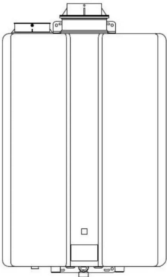
| Dimensions (W x H x D) | 451 x 700 x 235 mm |
| Weight (empty) | Approximately 24 kg |
| Power supply | 120 V AC, 60 Hz, standard 3-prong plug |
| Usable gas | Natural gas or propane (depending on configuration) |
| Water connections | Cold water inlet and hot water outlet 3/4" NPT |
| Venting type | Direct vent (outside combustion air) – PVC/CPVC or concentric pipes |
| Vent diameter | 3" or 4" (PVC/CPVC) |
| Maximum vent length | 41 ft (12.5 m) in 3", 100 ft (30.5 m) in 4" |
| Hot water flow rate | Varies by temperature (refer to the ladder diagram) |
| Set temperature | Adjustable via controller (optional MC-91-2) or DIP switches |
| Safety features | Flame detection, freeze protection, vent blockage sensor, error code diagnostics |
| Maintenance | Clean water filter, flush heat exchanger (in case of LC code), manual drain |
| Freeze protection | Built-in down to -22°F (-30°C) for indoor models, requires draining if power failure |
| Certifications | ANSI Z21.10.3 · CSA 4.3, Low Lead (NSF/ANSI 372) |
| Warranty | Heat exchanger 12 years, parts 5 years, labor 1 year (residential) |
Frequently Asked Questions - RUCS65iP Rinnai
User questions about RUCS65iP Rinnai
0 question about this device. Answer the ones you know or ask your own.
Ask a new question about this device
Download the instructions for your Boiler in PDF format for free! Find your manual RUCS65iP - Rinnai and take your electronic device back in hand. On this page are published all the documents necessary for the use of your device. RUCS65iP by Rinnai.
USER MANUAL RUCS65iP Rinnai
Direct Vent Tankless Water Heater Installation and Operation Manual
FOR INDOOR APPLICATIONS ONLY
RUCS65i... REU-KCM2025FFU-US
RUCS75i... REU-KCM2528FFU-US
FOR OUTDOOR APPLICATIONS ONLY
RUS65e REU-KCM2025W-US
RUS75e REU-KCM2528W-US


Low Lead Content NSF/ANSI 372

SANITATION


ANSI Z21.10.3 dot CSA 4.3
READ ALL OF THE INSTRUCTIONS THOROUGHLY BEFORE INSTALLING OR OPERATING THIS WATER HEATER.
This manual provides information on the installation, operation, and maintenance of the water heater. For proper operation and safety, it is important to follow the instructions and adhere to the safety precautions.
A licensed professional must install the water heater according to the exact instructions in this manual.
The consumer must read the entire manual to properly operate the water heater and to have regular maintenance performed.

WARNING
If the information in these instructions is not followed exactly, a fire or explosion may result causing property damage, personal injury, or death.
-
Do not store or use gasoline or other flammable vapors and liquids in the vicinity of this or any other appliance.
WHAT TO DO IF YOU SMELL GAS -
Do not try to light any appliance.
- Do not touch any electrical switch; do not use any phone in your building.
- Immediately call your gas supplier from a neighbor's phone. Follow the gas supplier's instructions.
- If you cannot reach your gas supplier, call the fire department.
Installation and service must be performed by a licensed professional.
Table of Contents
Table of Contents 2
Safety Behaviors and Practices for the
Consumer and Installer 3
Installation Instructions
(for the licensed professional) 4
Prepare for Installation. 5
Determine Installation Location 6
Freeze Protection. 10
Checklist to Determine Installation Location...11
Mount to Wall. 11
Remove the Front Panel 11
Installation of Venting (indoor models only) ... 12
Determining Vent Configuration. 13
Twin Pipe PVC/CPVC Vent Installation. 20
Condensate 37
Checklist for Venting and Condensate
(indoor models only). 37
Installation of Plumbing 38
Checklist for Plumbing 41
Installation of Gas Supply 41
Connect Electricity 43
Adjustment for High Altitude Installations.....43
Adjustment for Vent Length
(indoor models only). 43
Checklist for Gas and Electricity. 43
Installation of Temperature Controller. 44
Final Checklist. 46
Technical Data 47
Specifications 47
Dimensions. 48
Pressure Drop and Water Flow Curves 49
Ladder Diagram. 50
Operation Instructions 51
Consumer Operation Guidelines for the
Safe Operation of your Water Heater 52
How to set the Temperature 53
How to use the Optional Temperature
Controller 54
Diagnostic Codes 56
Required Maintenance. 59
Freeze Protection and Winterization 60
Flushing the Heat Exchanger. 61
Manual Draining of the Water Heater.. 62
State Regulations. 63
Replacement Parts 64
Warranty. 65
French Version. 67
NOTICE: Rinnai sometimes shares customer contact information with businesses that we believe provide products or services that may be useful to you. By providing this information, you agree that we can share your contact information for this purpose. If you prefer not to have your information shared with these businesses, please contact customer service and ask not to have your information shared. We will however, continue to contact you with information relevant to the product(s) you registered and/or your account with us.
If you have any questions or feel that the manual is incomplete contact Rinnai at 1-800-621-9419.
Important Safety Information
Safety Definitions

This is the safety alert symbol. This symbol alerts you to potential hazards that can kill or hurt you and others.

DANGER
Indicates an imminently hazardous situation which, if not avoided, will result in personal injury or death.

WARNING
Indicates a potentially hazardous situation which, if not avoided, could result in personal injury or death.

CAUTION
Indicates a potentially hazardous situation which, if not avoided, could result in minor or moderate injury. It may also be used to alert against unsafe practices.
Safety Behaviors and Practices for the Consumer and Installer

WARNING
- Before operating, smell all around the appliance area for gas. Be sure to smell next to the floor because some gas is heavier than air and will settle on the floor.
- Keep the area around the appliance clear and free from combustible materials, gasoline, and other flammable vapors and liquids.
- Combustible construction refers to adjacent walls and ceiling and should not be confused with combustible or flammable products and materials. Combustible and/or flammable products and materials should never be stored in the vicinity of this or any gas appliance.
Always check the water temperature before entering a shower or bath. - To protect yourself from harm, before performing maintenance:
Turn off the electrical power supply by unplugging the power cord or by turning off the electricity at the circuit breaker. (The temperature controller does not control the electrical power.)
Turn off the gas at the manual gas valve, usually located immediately below the water heater.
Turn off the incoming water supply. This can be done at the isolation valve immediately below the water heater or by turning off the water supply to the building.
- Use only your hand to push in or turn the gas control knob. Never use tools. If the knob will not push in or turn by hand, do not try to repair it; call a licensed professional. Force or attempted repair may result in a fire or explosion.
- Do not use this appliance if any part has been under water. Immediately call a licensed professional to inspect the appliance and to replace any part of the control system and any gas control which has been under water.
- Do not use substitute materials. Use only parts certified for the appliance.
- Should overheating occur or the gas supply fail to shut off, turn off the manual gas control valve to the appliance.
- Do not adjust the DIP switch unless specifically instructed to do so.
- Do not use an extension cord or an adapter plug with this appliance.
- Any alteration to the appliance or its controls can be dangerous and will void the warranty.
- Proper venting is required for the safe operation of this appliance.

CAUTION
-
BURN HAZARD. Hot exhaust and vent may cause serious burns. Keep away from the water heater unit. Keep small children and animals away from the unit.
-
Hot water outlet pipes leaving the unit can be hot to touch. In residential applications, insulation must be used for hot water pipes below 36 due to burn risk to children.

WARNING
California law requires this notice to be provided:
California Proposition 65:
This product contains chemicals known to the state of California to cause cancer, birth defects, or other reproductive harm.
Installation Instructions (for the licensed professional)
A licensed professional must install the appliance, inspect it, and leak test it before use. The warranty will be voided due to any improper installation.
The installer should have skills such as:
Gas sizing.
- Connecting gas lines, water lines, valves, and electricity.
- Knowledge of applicable national, state, and local codes.
- Installing venting through a wall or roof.
- Training in installation of tankless water heaters. (Training can be accessed on-line at www.trainingevents.rinnai.us)
Type of installation
- For installation in residential applications only.
- Certified for installation in manufactured (mobile) homes.
Installation Steps
Prepare for Installation 5
Determine Installation Location. 6
Freeze Protection. 10
Checklist to Determine Installation Location...11
Mount to Wall. 11
Remove the Front Panel 11
Installation of Venting (indoor models only) ...12
Condensate (indoor models only). 37
Checklist for Venting and Condensate 37
Installation of Plumbing 38
Checklist for Plumbing 41
Installation of Gas Supply. 41
Connect Electricity 43
Adjustment for High Altitude Installations ....43
Adjustment for Vent Length (indoor models only) 43
Checklist for Gas and Electricity. 43
Installation of Temperature Controller. 44
Final Checklist. 46
General Instructions Installer Qualifications
DO NOT
- Do not install the RUCS65i, or the RUCS75i outdoors.
- Do not install the RUS65e, or the RUS75e indoors.
- Do not install the appliance in an area where water leakage of the unit or connections will result in damage to the area adjacent to the appliance or to lower floors of the structure. When such locations cannot be avoided, it is recommended that a suitable drain pan, adequately drained, be installed under the appliance. The pan must not restrict combustion air flow.
- Do not obstruct the flow of combustion and ventilation air. Combustion air shall not be supplied from occupied spaces.
- Do not use this appliance in an application such as a pool or spa heater that uses chemically treated water. (This appliance is suitable for filling large or whirlpool spa tubs with potable water.)
- Do not use substitute parts that are not authorized for this appliance.
MUST DO
- The installation must conform with local codes or, in the absence of local codes, with the National Fuel Gas Code, ANSI Z223.1/NFPA 54, or the Natural Gas and Propane Installation Code, CSA B149.1. If installed in a manufactured home, the installation must conform with the Manufactured Home Construction and Safety Standard, Title 24 CFR, Part 3280 and/or CAN/SCA Z240 MH Series, Mobile Homes.
- The appliance, when installed, must be electrically grounded in accordance with local codes or, in the absence of local codes, with the National Electrical Code, ANSI/NFPA 70, or the Canadian Electrical Code, CSA C22.1.
- The appliance and its appliance main gas valve must be disconnected from the gas supply piping system during any pressure testing of that system at test pressures in excess of 1/2 psi (3.5kPa) (13.84 in W.C.).
General Instructions (continued)
- The appliance must be isolated from the gas supply piping system by closing its individual manual shutoff valve during any pressure testing of the gas supply piping system at test pressures equal to or less than 1/2 psi (3.5kPa) (13.84 in W.C.).
- You must follow the installation instructions and those in Care and Maintenance for adequate combustion air intake and exhaust.
INFORMATION
- If a water heater is installed in a closed water supply system, such as one having a backflow preventer in the cold water supply line, means shall be provided to control thermal expansion. Contact the water supplier or local plumbing inspector on how to control thermal expansion.
- Should overheating occur or the gas supply fail to shut off, turn off the manual gas control valve to the appliance.
- Keep the air intake location free of chemicals, such as chlorine or bleach, that produce fumes. These fumes can damage components and reduce the life of your appliance.
Prepare for installation
Parts included
Tankless water heater
Self Tapping Screws (Qty - 2)
Tools needed
- Pipe wrenches (2)
- Adjustable pliers
Screwdrivers (2) - Wire cutters
Gloves
- Safety glasses
- Level
Tools that might be needed
- Hammer drill with concrete bits
- Saw
- Threading machine with heads and oiler
Core drill with diamond head
- Torch set
Copper tubing cutter
- Steel pipe cutter
Materials needed
-
Soap or gas leak detector solution
Approved venting -
Teflon tape (recommended) or pipe compound
Pressure Relief Valve
Materials that may be needed
Heat tape
- Pipe insulation
- Electrical wire and conduit per local code
Concrete wall anchors
- Optional pipe cover
- Optional temperature controller (MC-91-2)
- PVC glue/cement
- 5 / 8'' ID PVC flexible tubing
2 conductor 22 AWG wire for controller - Single gang electrical box
Wire nuts - Unions and drain valves
- Isolation Valve Kit
Determine Installation Location
You must ensure that clearances will be met and that the vent length will be within required limits. Consider the installation environment, water quality, and need for freeze protection. Requirements for the gas line, water lines, electrical connection, and condensate disposal can be found in their respective installation sections of this manual.
Water Quality
Consideration of care for your water heater should include evaluation of water quality.
The water must be potable, free of corrosive chemicals, sand, dirt, or other contaminates. It is up to the installer to ensure the water does not contain corrosive chemicals, or elements that can affect or damage the heat exchanger. Water that contains chemicals exceeding the levels below affect and damage the heat exchanger. Replacement of the heat exchanger due to water quality damage is not covered by the warranty.
| Maximum Level | |
| Total Hardness Up to 200 mg / L | |
| Aluminum * Up to 0.2 mg / L | |
| Chlorides * Up to 250 mg / L | |
| Copper * Up to 1.0 mg / L | |
| Dissolved Carbon Dioxide (CO2) Up to 15.0 mg / L or PPM | |
| Iron * Up to 0.3 mg / L | |
| Manganese * Up to 0.05 mg / L | |
| pH * 6.5 to 8.5 | |
| TDS (Total Dissolved Solids) * Up to 500 mg / L | |
| Zinc * Up to 5 mg / L | |
- Source: Part 143 National Secondary Drinking Water Regulations
If you install this water heater in an area that is known to have hard water or that causes scale build-up the water must be treated and may require more frequent heat exchanger flushing schedule.
When scale build-up in the heat exchanger begins to affect the performance of the water heater, a diagnostic code "LC#" will display. Flush the heat exchanger to prevent damage to it. Scale build up is caused by hard water and can be accelerated if the unit is set at a high temperature.
Rinnai offers Southeastern Filtration's "ScaleCutter Water Conditioning System" that offers superior lime scale prevention and corrosion control by feeding a blend of control compounds into the cold water supply.
| Part Number Description | |
| 103000038 | Southeastern Filtratronn ScaleCutter System 3/4" Feed |
| 103000039 | ScaleCutter Refill |
Environment
Air surrounding the water heater, venting, and vent termination(s) is used for combustion and must be free of any compounds that cause corrosion of internal components. These include corrosive compounds that are found in aerosol sprays, detergents, bleaches, cleaning solvents, oil based paints/ varnishes, and refrigerants. The air in beauty shops, dry cleaning stores, photo processing labs, and storage areas for pool supplies often contains these compounds. Therefore it is recommended that outdoor models be used for these locations where possible.
The water heater, venting, and vent termination(s) should not be installed in any areas where the air may contain these corrosive compounds. If it is necessary for a water heater to be located in areas that may contain corrosive compounds, the following instructions are strongly recommended.
IMPORTANT CONSIDERATIONS FOR:
Indoor/Internal Water Heaters
- DO NOT Install in areas where air for combustion might be contaminated with chemicals.
- Before installation, consider where air has the ability to travel within the building to the water heater.
- Where possible, install the water heater in a sealed closet so that it is protected from the potential of contaminated indoor air.
Chemicals that are corrosive in nature should not be stored or used near the water heater.
Outdoor/External Water Heaters and Vent
Terminations of Indoor/Internal Water Heaters
- Install the water heater as far away as possible from exhaust vent hoods.
- Install as far away as possible from any air inlet vents. Corrosive fumes may be released through these vents when air is not being brought in through them.
Chemicals that are corrosive in nature should not be stored or used near the water heater or vent termination.
Damage and repair due to corrosive compounds in the air is not covered by warranty.
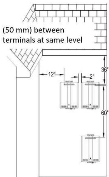
Direct Vent Terminal Clearances (Indoor Units)
For indoor models, you must install a vent termination to bring in combustion air and expel exhaust to the outside.

| Ref | Description | Canadian Installations US Installations | |
| A | Clearance above grade, veranda, porch, deck, or balcony | 12 inches (30 cm) | 12 inches (30 cm) |
| B | Clearance to window or door that may be opened | 36 inches (91 cm) | 12 inches (30 cm) |
| C | Clearance to permanently closed window | * | * |
| D | Vertical clearance to ventilated soffit, located above the terminal within a horizontal distance of 2 feet (61 cm) from the center line of the terminal | * * | |
| E | Clearance to unventilated soffit | * | * |
| F | Clearance to outside corner | * | * |
| G | Clearance to inside corner | * | * |
| H | Clearance to each side of center line extended above meter/regulator assembly | 3 feet (91 cm) within a height 15 feet (4.5 m) above the meter/regulator assembly | * |
| I | Clearance to service regulator vent outlet | 36 inches (91 cm) | * |
| J | Clearance to nonmechanical air supply inlet to building or the combustion air inlet to any other appliance | 36 inches (91 cm) 12 inches (30 cm) | |
| K | Clearance to a mechanical air supply inlet | 6 feet (1.83 m) | 3 feet (91 cm) above if within 10 feet (3 m) horizontally |
| L | Clearance above paved sidewalk or paved driveway located on public property | 7 feet (2.13 m) ① * | |
| M | Clearance under veranda, porch, deck, or balcony | 12 inches (30 cm) ② | * |
[1] A vent shall not terminate directly above a sidewalk or paved driveway that is located between two single family dwellings and serves both dwellings.
[2] Permitted only if veranda, porch, deck, or balcony is fully open on a minimum of two sides beneath the floor.
- For clearances not specified in ANSI Z223.1/NFPA 54, clearances are in accordance with local installation codes and the requirements of the gas supplier.
Clearance to opposite wall is 24 inches (60cm)

Other Than Direct Vent Terminal Clearances (Outdoor Units)
| Ref | Description | Canadian Installations(CSA B149.1) | US Installations(ANSI Z223.1 / NFPA 54) |
| A | Clearance above grade, veranda, porch, deck, or balcony | 12 inches (30 cm) | 12 inches (30 cm) |
| B | Clearance to window or door that may be opened | 6 in (15 cm) for appliances ≤ 10,000 Btuh (3 kW), 12 in (30 cm) for appliances > 10,000 Btuh (3 kW) and ≤ 100,000 Btuh (30 kW), 36 in (91 cm) for appliances >100,000 Btuh (30 kW) | 4 ft (1.2 m) below or to side of opening;1 ft (300 mm) above opening |
| C | Clearance to permanently closed window | * | * |
| D | Vertical clearance to ventilated soffit, located above the terminal within a horizontal distance of 2 feet (61 cm) from the center line of the terminal | * * | |
| E | Clearance to unventilated soffit | * | * |
| F | Clearance to outside corner | * | * |
| G | Clearance to inside corner | * | * |
| H | Clearance to each side of center line extended above meter/regulator assembly | 3 feet (91 cm) within a height 15 feet (4.5 m) above the meter/regulator assembly | * |
| I | Clearance to service regulator vent outlet | 36 inches (91 cm) | * |
| J | Clearance to non-mechanical air supply inlet to building or the combustion air inlet to any other appliance | 6 in (15 cm) for appliances ≤ 10,000 Btuh (3 kW), 12 in (30 cm) for appliances > 10,000 Btuh (3 kW) and ≤ 100,000 Btuh (30 kW), 36 in (91 cm) for appliances >100,000 Btuh (30 kW) | 4 ft(1.2 m)below or to side of opening;1 ft (300 mm) above opening |
| K | Clearance to a mechanical air supply inlet | 6 feet (1.83 m) | 3 feet (91 cm) above if within 10 feet (3 m) horizontally |
| L | Clearance above paved sidewalk or paved driveway located on public property | 7 feet (2.13 m) ① | * |
| M | Clearance under veranda, porch, deck, or balcony | 12 inches (30 cm) ② | * |
[1] A vent shall not terminate directly above a sidewalk or paved driveway that is located between two single family dwellings and serves both dwellings.
[2] Permitted only if veranda, porch, deck, or balcony is fully open on a minimum of two sides beneath the floor.
- For clearances not specified in ANSI Z223.1/NFPA S4, clearances are in accordance with local installation codes and the requirements of the gas supplier.
Clearance to opposite wall is 24 inches (60cm)
8 KCM Series Manual
Additional clearances
Check to determine whether local codes supersede these clearances.
- Avoid termination locations near a dryer vent.
- Avoid termination locations near commercial cooking exhaust.
- Avoid termination locations near any air inlets.
- You must install a vent termination at least 12 inches above the ground or anticipated snow level.
RUCS65i, RUCS75i
The vent for this appliance shall not terminate
Over public walkways; or
Near soffit vents or crawl space vents or other area where condensate or vapor could create a nuisance or hazard or cause property damage; or
- Where condensate or vapor could cause damage or could be detrimental to the operation of regulators, relief valves, or other equipment. Important considerations for locating vent termination under a soffit (ventilated or unventilated or eave vent; or to a deck or porch)
- Do not install vent termination under a soffit vent such that exhaust can enter the soffit vent
- Install vent termination such that exhaust and rising moisture will not collect under eaves. Discoloration to the exterior of the building could occur if installed too close.
- Do not install the vent termination too close under the soffit where it could present recirculation of exhaust gases back into the combustion air intake part of the termination.
RUS65e, RUS75e
(0.91 m) to ventilated or unventilated soffit or eve vent; or to a deck or porch
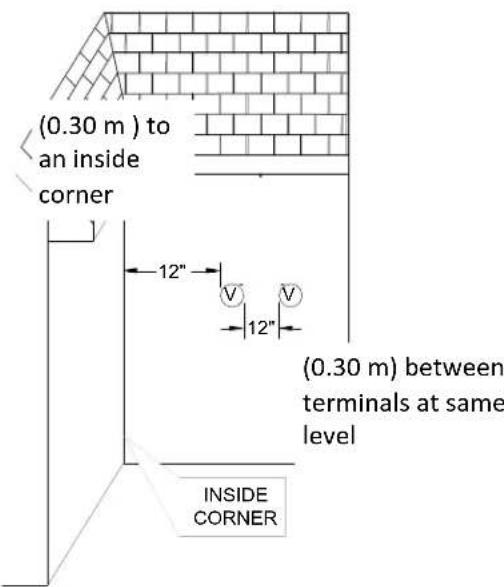
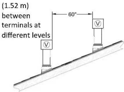
(1.52 m) vertically between terminals
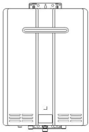
(0.30 m) to an inside corner


(0.30 m) between terminals at same level

Unit clearances
to floor/ground
| Indoor models: RUCS65i, RUCS75i | to Combustibles inches (mm) | to Non-Combustibles inches (mm) |
| Top of Heater | 6* (152) | 2*(51) |
| Back of Heater | 0 (zero) | 0 (zero) |
| Front of Heater | 6 (152) | 6 (152) |
| Sides of Heater | 2 (51) | 1/2 (13) |
| Ground/Bottom | 12 (305) | 12 (305) |
| Vent | 0 (zero) 0 (zero) |
- 0 inches from vent components and condensate drain line.
The clearance for servicing is 24 inches in front of the water heater.
For closet installation, clearance is 6 inches (152 mm from the front of the water heater.
| to Non-Combustibles | inches (mm) |
| Top of Heater | 12 (305) | 2 (51) |
| Back of Heater | 0 (zero) | 0 (zero) |
| Front (panel) | 24 (610) | 0 (zero) |
| Front (exhaust) | 24 (610) | 24 (610) |
| Sides of Heater | 6 (152) | 1/8 (3.2) |
| Ground/Bottom | 12 (305) | 2 (51) |
The clearance for servicing is 24 inches in front of the water heater.
Freeze Protection
Make sure that in case of freezing weather the water heater and its water lines are protected to prevent freezing. Damage due to freezing is not covered by the warranty.
With electrical power and gas supplied, the water heater will not freeze when the outside air temperature is as cold as -22ircF (-30ircC) for indoor models or is as cold as -4ircF (-20ircC) for outdoor models, when protected from direct wind exposure. Because of the "wind-chill" effect, any wind or circulation of the air on the unit will reduce its ability to protect itself from freezing.
In the event of a power failure and/or gas interruption at temperatures below freezing the water heater should be drained of all water to prevent freezing damage. In addition, drain the condensate trap and drain line.
Loss of freeze protection may result in water damage from a burst heat exchanger or water lines.
The unit may be drained manually. However, it is highly recommended to:
- drain down solenoid valves be purchased and installed that will automatically drain the unit if power is lost. These are available in a kit, 104000059. (The condensate trap is not affected by the auto drain down solenoid valves and will have to be manually drained.)
- a surge protector with terminals be purchased and installed which allows the solenoid valves to operate if the unit is disabled due to a diagnostic code. This is available as 104000057.
In addition, the solenoid valves should be connected electrically to a surge protector with terminals. This allows the solenoid valves to operate if the water heater is disabled due to a diagnostic code.
The freeze protection features of the water heater will not prevent the external piping from freezing. It is recommended that hot and cold water pipes be insulated. Pipe cover enclosures may be packed with insulation for added freeze protection.
It is recommended that the condensate trap drain line be insulated. A frozen condensate trap results in a diagnostic code 25.
Checklist to Determine Installation Location
The water heater is not exposed to corrosive compounds in the air.
The water heater location complies with all required clearances.
For indoor models, the planned venting will not exceed the maximum length for the number of elbows used.
The planned venting termination/air intake location meets all required clearances.
Indoor air is not being used for combustion.
The water supply does not contain chemicals or exceed total hardness that will damage the heat exchanger.
A standard 3 prong 120 VAC, 60Hz properly grounded wall outlet (for indoor models) or other 120 VAC, 60Hz source is available.
The installation must conform with local codes or, in the absence of local codes, with the National Fuel Gas Code, ANSI Z223.1/NFPA 54, or the Natural Gas and Propane Installation Code, CSA B149.1. If installed in a manufactured home, the installation must conform with the Manufactured Home Construction and Safety Standard, Title 24 CFR, Part 3280 and/or CAN/SCA Z240 MH Series, Mobile Homes.
Leave the entire manual taped to the water heater (indoor models) or give the entire manual directly to the consumer.
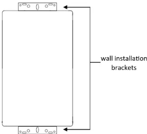
Mount to Wall
- Identify the installation location and confirm that the installation will meet all required clearances.
- Securely attach the water heater to the wall using any of the holes in the wall installation brackets which are at the top and bottom of the water heater. Ensure that the attachment strength is sufficient to support the weight of the water heater. Refer to the weight of the water heater in the Specifications section of this manual.
Use a leveling tool to ensure that the water heater is level. Proper operation requires that the water heater be level.
NOTICE
The water heater must be installed in an upright position. Do not install upside down or on its side.
Remove the Front Panel
- Slide the plastic trim pieces on each side of the water heater to expose the screws.
Remove the 4 screws and pull off the front panel.
Installation of Venting (indoor models only)
Install the correct venting for your model according to the venting manufacturer's instructions and the guidelines below. Refer to the vent manufacturer's technical literature for specific part numbers and instructions.
Approved Vent Manufacturers
| Manufacturer | Listed and Tested Vent Products | Telephone | Fax | Contact |
| Ubbink | Rolux Condensing Vent System | 800-621-9419 | 678-829-1666 | www.rinnai.us |
| Centrotherm | InnoFlue Vent System (single wall SW, 3 inch diameter) | 877-434-3432 | 518-618-3166 | info@centrotherm.us.com www.centrotherm.us.com |
| Heat-Fab | Saf-T Vent SC system | 800-772-0739 | 413-863-4803 | custsvc@heat-fab.com, www.heatfab.com |
| Metal-Fab | Corr/Guard Vent/Air Intake System | 800-835-2830 | 316-943-2717 | info@mtlfab.com, www.metal-fabinc.com |
| Ipex | Concentric Kit / Low Profile Termination Kit | U.S. - 800-463-9572 CA. - 866-473-9462 | — | www.ipexamerica.com www.ipexinc.com |
| Various Manufacturers | Schedule 40 PVC DWV Solid Core Pipe (or approved equal) CPVC schedule 40 | — | — |
Approved Vent Products
| Manufacturer | Vent Product | Vertical Termination | Horizontal Termination |
| Ubbink | Rolux | 184162PP | 223176PP, 223177PP |
| Centrotherm | InnoFlue | ICRT3539 | ISELL0387UV |
| Heat-Fab | Saf-T Vent | Saf-T Vent CI Plus Wall Termination | Saf-T Vent CI Plus Rain Cap |
| Metal-Fab | Corr/Guard | 3CGRVDK | 3CGRVT |
| Ipex | Concentric Kit | 3”- 196006 /1970094”-196021 /197021 | 3”- 196006 / 1970094”-196021 / 197021 |
| Ipex | Low Profile Termination Kit | — | 3”- 1969854”- 196986 |
| Various Manufacturers | Schedule 40 PVC DWV Solid Core Pipe (or approved equal) CPVC schedule 40 | Reference “Approved PVC/CPVC Vent Configurations” Table | Reference “Approved PVC/ CPVC Vent Configurations” Table |
Proper venting is required for the safe operation of this appliance.
Venting Guidelines
DO NOT
- Do not use cellular core PVC/CPVC.
- Do not use Radel, ABS, or galvanized material to vent this appliance.
- Do not cover non-metallic vent pipe and fittings with thermal insulation.
- Do not combine vent components from different manufacturers.
- Vent diameter must not be reduced.
- Do not connect the venting system with an existing vent or chimney.
- Do not common vent.
MUST DO
- This water heater is a direct vent water heater and therefore is certified and listed with the vent system. You must use vent components that are certified and listed with the water heater model.
The vent system must vent directly to the outside of the building and use outside air for combustion. - Avoid dips or sags in horizontal vent runs by installing supports per the vent manufacturer's instructions.
Support horizontal vent runs every four feet and all vertical vent runs every six feet or in accordance with local codes. - Venting should be as direct as possible with a minimum number of pipe fittings.
- Vent connections must be firmly pressed together so that the gaskets form an air tight seal.
- The vent piece connected to the water heater must be secured with one self-tapping screw.
INFORMATION
Refer to the instructions of the vent system manufacturer for component assembly instructions.
- If the vent system is to be enclosed, it is suggested that the design of the enclosure permit inspection of the vent system. The design of such enclosure shall be deemed acceptable by the installer or the local inspector.
NOTICE
If it becomes necessary to access an enclosed vent system for service or repairs, Rinnai is not responsible for any costs or difficulties in accessing the vent system. The warranty does not cover obtaining access to a vent system in an enclosed environment.
Determining Vent Configuration
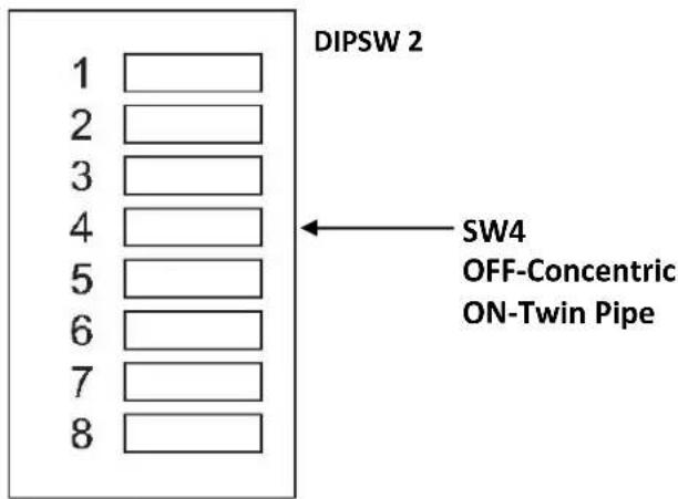
Prior to the installation of the vent system, the dip switches on the PCB board must be properly set for the venting configuration selected for the application. (Unit comes defaulted for concentric applications)
| Venting Dip Switch Settings | |
| Venting Style SW4 | in DIPSW 2 |
| Concentric OFF | |
| Twin Pipe ON | |
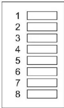
DIPSW1
Determining Vent Configuration

NOTICE
- Prior to the installation of the vent system, the unit must be properly adjusted for the venting configuration selected for the application.
- Any issues resulting from improper installation will not be covered by warranty.
- Ducted outside air is mandatory for all twin pipe configurations.

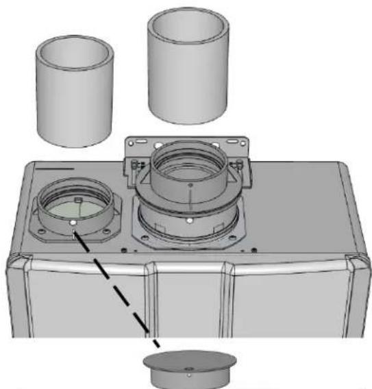
Concentric Vent Configuration (Same procedure to be used for Twin Pipe with Centrotherm Adapter Configuration)
Removal of Exhaust Adapter Ring
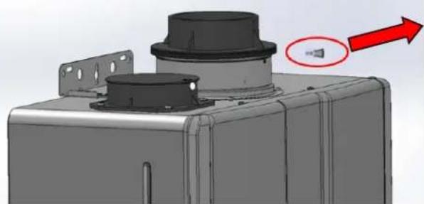
1. Remove fastener from concentric flue connection.

2. Remove exhaust adapter ring.
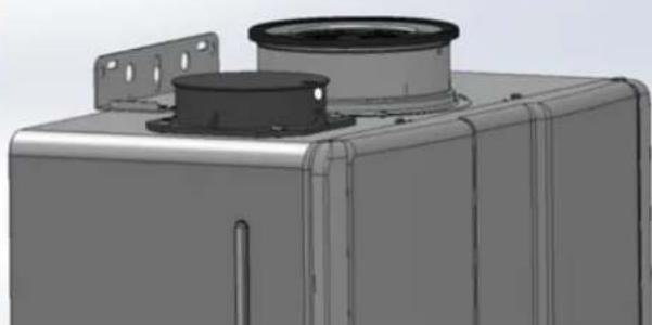
3. Install the concentric vent. Ensure it is properly seated.
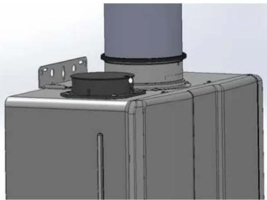
4. Secure the vent pipe to the unit with a screw

Determining Vent Configuration (continued)
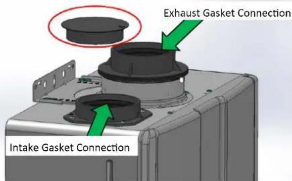
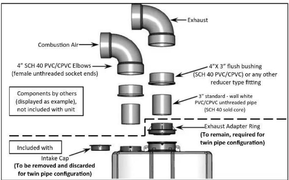
Twin Pipe PVC/CPVC Configuration (3"or 4")
Intake Cap to be removed and discarded for twin pipe PVC/CPVC configuration.
Removal of Intake Cap
- Remove the fastener from intake connection.
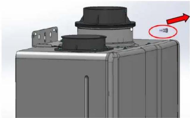
- Remove the intake cap.
- Install the intake pipe. Ensure it is properly seated.
- Secure the intake pipe to the unit with the supplied screw (in the carton box).
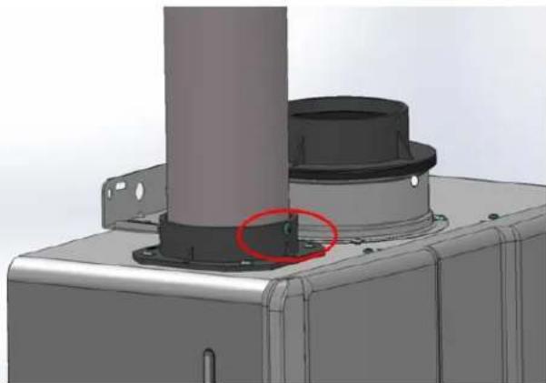
- Install the exhaust pipe. Ensure it is properly seated.
- Secure the exhaust pipe to the unit with the supplied screw (in the carton box).


WARNING
DO NOT apply PVC glues, solvents, or cleaners to the water heaters intake or exhaust gasket connections. Failure to correctly assemble the components according to these instructions may result in property damage, personal injury, or death.
Maximum vent length
Maximum Vent Length with Concentric Venting
- Determine the number of 90 degree elbows in the vent system. (Two 45 degree elbows count as one 90 degree elbow.)
- Refer to the table to find the maximum vent length based on the number of elbows.
- Adjust SW1 in DIPSW 1 (tan switches) if required by the applicable note.
| Ubbink Concentric (90° elbow is equivalent to 6 feet; 45° elbow is equivalent to 3 feet.) | |
| Maximum Equivalent Vent Length 41 ft (12.5 m) | |
| # of 90° Elbows | Maximum Vent Length in feet (meters) |
| 0 41 (12.5) | 1 |
| 1 35 (10.7) | 2 |
| 2 29 (8.8) | 3 |
| 3 23 (7.0) | 4 |
| 4 17 (5.2) | 4 |
| 5 11 (3.4) | 4 |
| 6 5 (1.5) | 4 |
① If the length is greater than 21 ft (6.4m) then move SW1 to OFF.
If the length is greater than 15 ft (4.6 m) then move SW1 to OFF.
③ If the length is greater than 9 ft (2.7m) then move SW1 to OFF.
④ Move SW1 to OFF.
Example: If you have one elbow then your maximum vent length is 35 feet (10.7 m). If your actual length is greater than 15 ft (4.6 m) then move SW1 in DIPSW 1 to OFF.
NOTICE
If you have a longer vent length (see number 3 regarding max. vent length), SW1 in DIPSW 1 is required to be in the OFF position. This ensures the water heater will run properly. Blocked flue diagnostic codes and shutdowns may result if SW1 in DIPSW 1 is not in the correct position.
Maximum Vent Length for Centrotherm 2 Pipe
InnoFlue Vent System (single wall SW, 3 inch diameter)
Vent length using short radius elbow
(Intake is the short UV protected 90irc elbow)
| Number of 90° Short Radius Elbows | Maximum Straight Vent Length | SW1 in DIPSW 1 If length is greater than: |
| 0 41 ft | (12.50 m) | 18 ft (5.49 m) move SW1 to OFF |
| 1 26 ft | (7.93 m) | 3 ft (0.91 m) move SW1 to OFF |
| 2 11 ft | (3.35 m) | move SW1 to OFF for any length |
Vent length using long radius elbow
(Intake is the long UV protected 90irc elbow)
| Number of 90° Long Radius Elbows | Maximum Straight Vent Length | SW1 in DIPSW 1 If length is greater than: |
| 0 41 ft | (12.50 m) 21 ft (6.40 m) move | |
| 1 35 ft | (10.67 m) 15 ft (4.57 m) move | |
| 2 29 ft | (8.84 m) 9 ft (2.74 m) move | |
| 3 23 ft | (7.01m) 3 ft (0.91 m) move | |
| 4 17 ft | (5.18 m) | move SW1 to OFF for any length |
| 5 11 ft | (3.35 m) | |
| 6 5 ft | (1.52 m) |
Maximum vent length
Maximum Vent Length with Twin Pipe PVC / CPVC
| Twin Pipe 3" PVC / CPVC (90° elbow is equivalent to 5 feet; 45° elbow is equivalent to 2.5 feet.) | |
| Maximum Equivalent Vent Length 41 ft (12.5 m) | |
| # of 90° Elbows | Maximum Vent Length in feet (meters) |
| 0 41 (12.5)** | |
| 1 36 (11.0)** | |
| 2 31 (9.4)** | |
| 3 26 (7.9)** | |
| 4 21 (6.4)** | |
| 5 16 (4.9)** | |
| 6 11 (3.4)** | |
| Twin Pipe 4" PVC / CPVC (90° elbow is equivalent to 5 feet; 45° elbow is equivalent to 2.5 feet.) | |
| Maximum Equivalent Vent Length 100 ft (30.5 m) | |
| # of 90° Elbows | Maximum Vent Length in feet (meters) |
| 0 100 (30.5) | ** |
| 1 95 (29.0) | ** |
| 2 90 (27.4) | ** |
| 3 85 (25.9) | ** |
| 4 80 (24.4) | ** |
| 5 75 (22.9) | ** |
| 6 70 (21.3) | ** |
**SW 1 in DIPSW 1 is "OFF" for lengths greater than or equal to 21 feet.
(See Twin Pipe PVC/CPVC Vent Installation section for more information regarding equivalent vent length calculations.)
Flue Installation with Concentric Venting (indoor models only)
Install the venting termination according to the diagrams and instructions below.
Slope the venting 1 / 4'' per foot toward the appliance according to the vent manufacturers installation instructions.
Vertical Termination

Slope the venting 1 / 4'' per foot toward the appliance according to the vent manufacturers installation instructions.
Secure the first vent component to the water heater with one self-tapping screw at the hole.
Flue Installation with Centrotherm Venting (indoor models only)
Install the venting termination according to the diagrams and instructions below.
Comply with the exhaust clearances found in this Rinnai Installation and Operation Manual.
- Only one appliance can be attached to the vent system.
Install the system according to the Centrotherm installation instructions included with the vent system.
The vent termination and air intake must be in the same pressure zone.
- Do not exceed the maximum straight vent length with number of elbows as shown in the tables in the following section.
- Maintain the clearances shown in the figures below.
WARNING
The following vent materials are NOT APPROVED for use with this appliance:
- Cellular core PVC/CPVC
Radel, ABS, and/or Galvanized ducts.
Failure to use approved vent materials can result in property damage, personal injury, or death.

Vertical Termination
Horizontal Termination
Slope horizontal exhaust run towards the water heater 1/4'' per foot. DO NOT slope combustion air pipe towards unit. Be sure to dispose of condensate per local codes.

WARNING
Installations must comply with local requirements and with the National Fuel Gas Code, ANSI Z223.1/NFPA 54 for U.S. installations or CSA B149.1 for Canadian installations. DO NOT use cellular core PVC, CPVC, or Radel based pipe materials for the exhaust vent. Vents MUST be of solid core pipes ONLY.

WARNING
Use only the materials listed in this section for vent, air intake pipe, and fittings (See vent and air piping materials table). Failure to comply with this warning could result in property damage, personal injury, or death.

DANGER
Tankless Water Heaters with PVC/CPVC venting must be configured with intake air and exhaust vent using piping and methods described in this section. Each water heater must have its own intake and vent. DO NOT common vent with any other appliance using this method. Inspect finished vent and intake air piping thoroughly to ensure all are airtight and comply with the instructions provided and with all requirements of applicable codes. Failure to provide a properly installed vent and air system will cause personal injury or death.

WARNING
Combustion Air Intake - The combustion air intake termination fitting must be installed with the clearances and geometry relative to the exhaust (vent) depicted in this section to ensure that flue products do not enter the combustion air intake. Ensure that the intake air will not contain any of the contaminants outlined in the "Determine Installation Location" section of this manual. Contaminated intake air will damage the water heater, resulting in possible property damage, personal injury, or death.
Exhaust - The exhaust (vent) termination fitting must be installed with the clearances and geometry relative to the combustion air pipe as depicted in this section to ensure that flue products do not enter the combustion air intake

WARNING
The installation must conform with local codes or, in the absence of local codes, with the National Fuel Gas Code, ANSI Z223.1/NFPA 54, or the Natural Gas and Propane Installation Code, CSA B149.1. DO NOT use cellular core PVC, CPVC, Radel, ABS, or galvanized material for the exhaust vent. Vents MUST be of solid core pipes ONLY.

WARNING
Use only the materials listed in this manual for vent, combustion air intake pipe, and fittings (See "Vent and Air Piping" table). Failure to comply with this warning could result in property damage, personal injury, or death.

WARNING
If used, a masonry chimney can ONLY be used as a CHIMINEY CHASE for the exhaust and combustion air intake pipes. The exhaust and air piping must be installed as instructed in this manual. The chimney chase must be used only for the Rinnai Water Heater(s) vent chase. NO OTHER appliance or fireplace can be connected to the chimney chase. Exhaust and air piping materials must comply with this instruction. The chimney chase must be fitted with a sealed access opening to facilitate interior inspection. The chimney chase (and liner, if installed) to be inspected annually for any degradation. Failure to comply could result in property damage, personal injury, or death.

NOTICE
If the vent and/or combustion air intake piping configurations covered in this manual cannot be applied to a specific installation, contact Rinnai's Application Engineer group for assistance. Other configurations may be available.
Twin Pipe PVC/CPVC Vent Installation Requirements:
- All PVC/CPVC IPEX Concentric Vent Kit (CVK) Assemblies are certified to ULC S636. Where ULC S636 compliance is required, use only System 636 pipe, fittings, and cement at terminal connection.
DO NOT use PVC/CPVC on Non-Condensing Units.
DO NOT operate unit until venting is completely installed and all solvents and glues have bonded. - All PVC/CPVC exhaust vent material used in Canada must be S636 certified.
For further details on listed PVC/CPVC venting material (table below) refer to the installation manual of the PVC/CPVC manufacturer.
IMPORTANT CONSIDERATIONS FOR LOCATION:
- Locate the vent outlet where flue gases will not harm surrounding plants and/or cooling equipment.
-
Avoid locating vent where prevailing winds could affect the performance of the water heater or cause recirculation of the flue gases.
DO NOT terminate the venting over a public walkway or over an area where condensate or vapor can create a nuisance / hazard or where condensate can be detrimental to the operation of equipment such as regulators or relief valves -
Water Heater flue gases must be piped from the appliance to the outside, Installer MUST adhere to the instructions provided herein and the most recent Water Heater Manual and all applicable codes.
- Exhaust and combustion air must terminate through the same sidewall or roof as the terminations must be in the same pressure zone and face same direction.
- Vent pipe must terminate either through the sidewall or through the roof, exhaust/vent termination and/or intake air openings shall adhere to clearances as set forth in the Direct Vent Termination Clearances diagram.
Each Condensing Tankless Water Heater requires a separate vent system. - For twin pipe installation use only 3'' or 4'' PVC/CPVC.
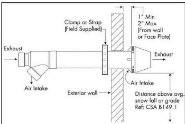
Terminations must be installed 12 above grade or anticipated snow level.
| Vent and Air Piping Materials | |||
| Item Material | Standard for Installation in North America | ||
| United States Canada | |||
| Thermoplastic Piping Materials | |||
| Vent or combustion air intake pipe & Fittings | PVC schedule 40 ANSI/ASTM D1785 | Thermoplastic vent pipe must be certified to ULC S636. Intake pipe may be of any material listed (left). | |
| PVC-DWV ANSI/ASTM D2665 | |||
| CPVC schedule 40 ANSI/ASTM F441 | |||
| PVC pipe cement & primer | PVC ANSI/ASTM D2564 | ||
| CPVC ANSI/ASTM F493 | |||
| IPEX bird screens (purchase separately) | |||
| Termination Vent Screens | Polyethylene | 3" Vent screen: IPEX part # 196051; 4" Vent screen: IPEX part #: 196052 (Screens are friction fitted inside termination fitting bells.) | |
| NOTE The listed vent, vent fittings, termination, cleaner, and glue are all certified as part of the condensing tankless water heater vent system. | |||
| DANGER Failure to correctly install vent and combustion air intake pipes of the water heater to atmosphere as outlined in this venting section will result in death from asphyxiation (from carbon monoxide), fire, or explosion. NEVER operate the water heater without proper venting (vent and combustion air intake). Always inspect the vent terminal unit, combustion air intake pipe, and the entire vent system affixed to the water heater for proper installation at equipment commissioning and at least annually thereafter. | |||
IMPORTANT CONSIDERATIONS FOR LOCATION (continued):
Exhaust and Combustion Air Intake Pipe Diameters and Maximum Lengths:
- For PVC/CPVC vent systems reduce the maximum allowable length for each elbow and termination type as follows:
2.5 feet for every 45irc elbow.
5 feet for every 90irc elbow.
Termination (refer to the Approved Vent Component table of this section)
- Vent and combustion air intake pipe diameters must not exceed the maximum equivalent vent lengths referenced within this manual.
- Do not exceed vent and combustion air intake pipe MAXIMUM lengths (Lengths are specific to models and fuel type).
Determining Total System Equivalent Length
There are two options for determining the vent lengths/ components necessary for the installation.
Option 1: The installer can use the vent length calculation sheet (below), filling in the quantity of the vent components in order to calculate the total equivalent vent lengths.
Option 2: The installer can use the maximum vent lengths tables on the next pages to determine the amount of straight pipe that can be used with a specific termination type and quantity of elbows.
OPTION 1:
Calculation of equivalent piping lengths for venting system:
Choose the vent type and fill out the calculation sheet below. When determining equivalent combustion air and vent length, add 5 feet for each 90irc elbow, 2.5 feet for each 45irc elbow.
Example of calculation (assume 3'' diameter pipes for natural gas unit):
- Twin pipe (parallel) with snorkel terminal
Combustion air pipe length: 16 ft straight pipe with 2 × 90irc elbows - Exhaust pipe length: 16 ft straight pipe with 2 × 90irc elbows (include all interior and exterior elbows)
- Snorkel Termination: 15 equivalent feet (reference Approved PVC/CPVC Termination Components table)
Calculation:
Equivalent Combustion air pipe length: [16 + (2× 5) + 15] = 41 ft
- Equivalent Vent Length: [16 + (2 × 5) + 15] = 41 ft
- Total = 41 ft. for both exhaust and combustion air pipes, which is the maximum allowable vent length for 3'' PVC/CPVC on a natural gas unit. If longer lengths are required, go to the 4'' diameter pipe configuration which is certified for up to 100 equivalent feet.

ATTENTION
Maximum equivalent vent lengths are specific to the fuel type of the water heater. It is imperative when performing vent calculations the following be taken into consideration:
| Vent Type | Maximum Equivalent Vent Length |
| 3” PVC/CPVC | 41 Feet |
| Concentric PP | 41 Feet |
| 4” PVC/CPVC | 100 Feet |
| Twin Pipe PP (Centrotherm) | 41 Feet |
Equivalent Vent Length Calculation Sheet
| Fitting / Termination Type | Number of fittings | Equivalent Vent Length | Total Equivalent Length | ||
| 1) 90 elbow | 2 | x | 5 | = | 10 |
| 2) 45 elbow | x | 2.5 | = | 0 | |
| 3) IPEX Low Profile Termination | x | 5 | = | 0 | |
| 4) IPEX 4" Concentric Termination | x | 20 | = | 0a | |
| 5) IPEX 3" Concentric Termination | x | 20 | = | 0 | |
| 6) 3" Tee Termination | x | 5 | = | 0 | |
| 7) 4" Tee Termination | x | 5 | = | 0 | |
| 8) 3" Snorkel Termination | 1 | x | 15 | = | 15 |
| 9) 4" Snorkel Termination | x | 15 | = | 0 | |
| 10) Length of Straight Section in feet | NA | 16 | = | 16 | |
| Total (add up lines 1 through 10) | 41 | ||||
(A blank copy of the Equivalent Vent Length Calculation Sheet is located at the end of this section)
Ensure SW1 in DIPSW 1 is in OFF position if vent length is greater than 21ft (6.4m).
OPTION 2:
Maximum Equivalent Vent Length Tables:
Determine the number of 90 degree elbows in the vent system. (two 45 degree elbows count as one 90 degree elbow.) Refer to the tables below to find the maximum vent length based on the number of elbows and termination style.
| Total Equivalent Vent Length (Intake/outlet) for Twin Pipe 3" PVC/CPVC | ||||
| Maximum Vent Length | 41 Feet | |||
| Termination Type | IPEX Concentric Vent Kit | Snorkel Termination | Side Wall Tee Termination | Low Profile Termination |
| Termination Equivalent Length in feet (meters) (Already factored into the straight pipe lengths below) | 20 (6.1) | 15 (3.0) | 5 (1.5) | 5 (1.5) |
| # of 90° Elbows (each: 5 equivalent feet) | Max. straight pipe vent length in feet (meters) | |||
| 0 | 21 (6.4) ** | 26 (7.9) ** | 36 (11.0) ** | 36 (11.0) ** |
| 1 | 16 (4.9) ** | 21 (6.4) ** | 31 (9.4) ** | 31 (9.4) ** |
| 2 | 11 (3.4) ** | 16 (4.9) ** | 26 (7.9) ** | 26 (7.9) ** |
| 3 | 6 (1.8) ** | 11 (3.4) ** | 21 (6.4) ** | 21 (6.4) ** |
| 4 | - | 6 (1.8) ** | 16 (4.9) ** | 16 (4.9) ** |
| 5 | - | 1 (0.4) ** | 11 (3.4) ** | 11 (3.4) ** |
| 6 | - | - | 6 (1.8) ** | 6 (1.8) ** |
| Total Equivalent Vent Length (Intake/outlet) for Twin Pipe 4" PVC/CPVC | ||||
| Maximum Vent Length | 100 Feet | |||
| Termination Type | IPEX Concentric Vent Kit | Snorkel Termination | Side Wall Tee Termination | Low Profile Termination |
| Termination Equivalent Length in feet (meters) (Already factored into the straight pipe lengths below) | 20 (6.1) | 15 (3.0) | 5 (1.5) | 5 (1.5) |
| # of 90° Elbows (each: 5 equivalent feet) | Max. straight pipe vent length in feet (meters) | |||
| 0 | 80 (24.4) ** | 85 (25.9) ** | 95 (29.0) ** | 95 (29.0) ** |
| 1 | 75 (22.9) ** | 80 (24.4) ** | 90 (27.4) ** | 90 (27.4) ** |
| 2 | 70 (21.3) ** | 75 (22.9) ** | 85 (25.9) ** | 85 (25.9) ** |
| 3 | 65 (19.8) ** | 70 (21.3) ** | 80 (24.4) ** | 80 (24.4) ** |
| 4 | 60 (18.3) ** | 65 (19.8) ** | 75 (22.9) ** | 75 (22.9) ** |
| 5 | 55 (16.8) ** | 60 (18.3) ** | 70 (21.3) ** | 70 (21.3) ** |
| 6 | 50 (15.2) ** | 55 (16.8) ** | 65 (19.8) ** | 65 (19.8) ** |
**SW 1 in DIPSW 1 is "OFF" for lengths greater than or equal to 21 feet

ATTENTION
Maximum vent lengths are specific to the fuel type of the tankless water heater. It is imperative when performing equivalent vent length calculations that the gas type be taken into consideration.
Installation of PVC/CPVC Vent and Intake Air Piping:
Adapter Installation Configurations:
Note the correct position of the combustion air inlet and gas flue outlet, as these are NOT interchangeable. For the correct position and design of the twin pipe gas flue outlet and combustion air inlet refer to the installation instructions in this manual.
WARNING
DO NOT apply PVC glues, solvents, or cleaners to the water heaters intake or exhaust gasket connections.
Required Parts For 3" PVC/CPVC Assembly Configuration
The RUCS series units do not require additional parts to be used with standard 3'' 3rd party solid core PVC/ CPVC pipes; refer to figure below for required parts for 3'' PVC/CPVC assembly configuration.

Required Parts For 4" PVC/CPVC Assembly Configuration
Conversely, the RUCS series units require 2 additional (4 × 3 Flush-Schedule 40 PVC) bushing to be used with 4 PVC/CPVC assembly configuration (refer to figure below).
WARNING
Failure to correctly assemble the components according to these instructions may result in property damage, personal injury, or death.
Certified PVC/CPVC Vent Termination Options
Vent Termination Configurations
There are 4 configurations for vent terminations that are approved for use with the RUCS series water heaters:
- Concentric Termination (IPEX Concentric Vent Kit) -Allows for only one penetration through a wall or roof.
- Snorkel Termination -Allows for easier clearance above grade when having to terminate through a lower point
- Side Wall Tee Termination
- IPEX Low Profile Termination -Used for flush mount side wall application only.
Termination Installation
- Exhaust and combustion air piping must be securely fastened to structure every 4 feet, to ensure dimensions shown in the Figures throughout this document are maintained.
- DO NOT strap vertical vent too tightly as the strapping must permit the vent to move in the event of expansion and contraction.
- Straps are field supplied. Use straps, clamps or equivalent that will not score or damage the pipe. Expansion and contraction should be addressed between appliance and termination point.
- All penetrations must be sealed according to local building codes. Caulking for side wall terminations and flashing for roof penetrations are typical. Use only PVC/ CPVC compatible sealing material. Contact PVC/CPVC manufacturer for a list of compatible materials.
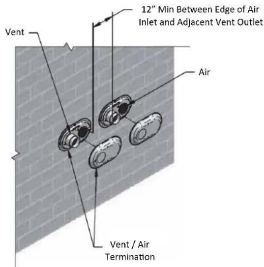
IPEX Concentric Vent Kit (CVK) Installation
- For installations with multiple terminations, maintain appropriate clearances between terminals. (Reference IPEX Concentric Vent Kit Clearance diagram)
- The pipe length of the concentric vent kit can be shortened; providing that the cutting and cementing procedures adhere to the System 636 guidelines; reference IPEX installation instructions for further information.
- Pipe lengths and/or fittings CANNOT be added to the socket of the rain cap in order to divert exhaust gas.
WARNING
Moisture in the flue gas will condense as it leaves the vent terminal. In cold weather this condensate can freeze on the exterior wall, under the eaves, and on surrounding objects. Some discoloration to the exterior of the building is to be expected. However, improper location or installation can result in damage to the structure or exterior finish of the building.
WARNING
Danger of fire or bodily injury - Solvent cements and primers are highly flammable. Provide adequate ventilation and do not assemble near a heat source or open flame. Do not smoke. Avoid contact with the skin or eyes. Observe all cautions and warnings on material containers.
Wall Termination

Roof Termination
Certified PVC/CPVC Vent Termination Options (continued)
IPEX Concentric Vent Kit Assembly (System 636):
- Once the proper location has been determined, cut a hole in the roof or wall large enough to accommodate the outer pipe. The size of the hole can vary greatly depending on the roof pitch.
- As per the procedures outlined, solvent cement the inner pipe to the concentric Wye fitting.
- Solvent cement the outer pipe to the concentric Wye fitting.
- Slide the assembly through the roof or wall penetration. (Install flashing as required)
- To permanently affix the rain cap, it should be solvent cemented to the inner pipe. For installations where removal of the cap may be required for service or cleaning the cap, it can be fastened mechanically (see instructions). For either installation method, the outer pipe is only a friction fit with the cap.
MECHANICALLY FASTENED RAIN CAP:
The Rain Cap must be installed with the supplied Stainless Steel screw and lock nut, and in accordance with the instructions and diagram below.
- Locate the drill location dimple on the outside of the rain cap.
- At this location, drill through the cap and the inner pipe wall. Ensure that the path of the hole is perpendicular to the inner pipe NOT the outside of the cap. For the 3 kit, drill a 3 / 16'' hole, for the 4 kit, drill a 1 / 4'' hole. Clean any resulting debris.
- Insert the screw and tighten, DO NOT OVER TIGHTEN.
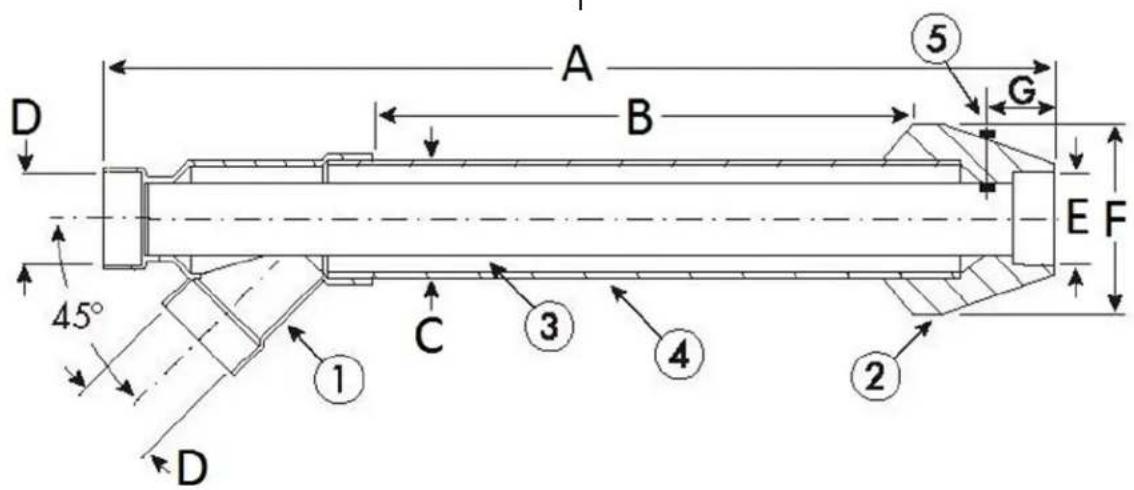
Twin Pipe to Concentric Termination Physical Data
| System 636 Concentric Vent Kits Termination Kits Include: | Nominal Pipe Size (Dimension in Inches) | |||||||
| Item # | Concentric Kit | A | B* | C+ | D | E | F | G |
| 196006 | 3" x 20" PVC | 36.1 | 20 | 4.5 | 3 | 3 | 8.75 | 2.25 |
| 196021 | 4" x 36" PVC | 56 | 37.3 | 6.62 | 4 | 4 | 10 | 3.5 |
| 197009 | 3" x 20" CPVC | 36.1 | 20 | 4.5 | 3 | 3 | 8.75 | 2.25 |
| 197021 | 4" x 36" CPVC | 56 | 37.3 | 6.62 | 4 | 4 | 10 | 3.5 |
| 1 Wye - (Concentric)2 Rain Cap3 Exhaust Vent Pipe (Inner)4 Fresh Air Intake Pipe (Outer)5 Stainless Steel Screw & Nut | B* Dimension be may be shortened to a minimum of 12". Inner pipe (item 3) must remain "F" inches longer than the outer pipe (item 4). Cut pipe ends square and solvent cement as outlined in the System 636 installation manual.C+ Installation cutout should be at least 1/2" larger than dimension "C".Lengthening the units is not permitted. | |||||||
IPEX CONCENTRIC VENT KIT (CVK) CLEARANCES:

ACCEPTABLE VENTING CLEARANCES FOR IPEX CONCENTRIC VENT KIT (CVK) TERMINATION
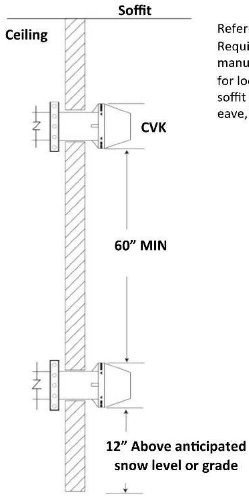
TWO OR MORE VENT TERMINALS ON SAME LEVEL
Vertical between Terminals
NOTE
Vent spacing depicted above is specific to the IPEX PVC/CPVC-FGV Concentric Vent Kit ONLY; for required spacing for all other termination types refer to subsequent pages of this manual.
| Table 8: Approved PVC/CPVC Vent Configurations | |||
| 3" or 4" PVC/ CPVC Concentric Side Wall Termination Configuration | Water Heater | 3" or 4" PVC/ CPVC Concentric Vertical Termination Configuration | Water Heater |
| 3" or 4" PVC/ CPVC Snorkel Termination Configuration | Water Heater | 3" or 4" PVC/ CPVC Standard upside down "U" Vertical Termination Configuration | Water Heater |
| 3" or 4" PVC/ CPVC Tee Side Wall Termination Configuration | Water Heater | 3" or 4" PVC/ CPVC Tee Vertical Termination Configuration | Water Heater |
| 3" or 4" PVC/ CPVC Low Profile Termination Configuration | Water Heater | ||
VENTING INSTALLATION SEQUENCE
- Install the water heater.
- Determine the termination method—sidewall or vertical, concentric, or separate pipes, etc.
- Determine proper location for wall or roof penetration for each termination.
- Install termination assembly as described in this manual.
KCM Series Manual 29
- Install air and vent piping from water heater to termination.
- Slope horizontal exhaust run towards the water heater 1/4'' per foot. DO NOT slope combustion air pipe towards unit. Be sure to dispose of condensate per local codes.
- Install pipe supports and brackets every 4 feet allowing for movement from expansion or as per local code requirements.
Certified PVC/CPVC Vent Termination Options (continued)
3" and 4" Low Profile Vent Termination Kits
The following information should be used in conjunction with the IPEX System 636 Installation Guide:
Termination kits are to be tested and certified for use with the brand of pipe-fitting-cement system that is to be utilized in the application. The IPEX Low Profile termination is fully certified for use with IPEX product only.
- System 636 PVC Low Profile Vent kits are rated to 65ircC maximum and are made from certified compound.
- All termination kits must be located and installed in accordance with these instructions, local building code, and CSA B149.1 Natural Gas and Propane Installation Code.
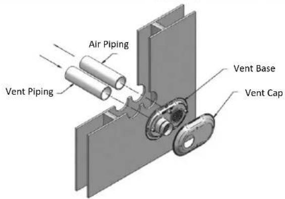
Installation:
- Once a proper location has been determined, cut 2 appropriately sized holes in the wall to accommodate the pipe. (Reference the Low Profile Termination Kit-Dimensions table below)
- Slide intake and exhaust pipes through the holes. Secure (using solvent cement) both pipes to the base of the vent termination kit. (Be sure to follow guidelines for solvent cementing as described in the System 696 Installation Guide)
- Use the supplied screws and anchors to secure the base to the wall. (a drilled 3 / 16'' hole, 1 - 3 / 16'' deep will be needed for the anchors.) Use the base as a template to locate the anchor hole.
- Using the supplied screws, secure the Cap to the Base.
- Upon securing the vent termination and pipes, seal the wall penetrations (from the interior) using a PVC compatible sealant material.

WARNING
All exhaust vents and air inlets must terminate at the same height to avoid property damage, personal injury, or death.
IPEX Low Profile Termination Kits-Dimensions
| Item # | Description | Pipe Outside Diameter | Hole Spacing (Ctr toCtr) |
| 196985 | 3" Flush Mount Vent Kit | 3.5” 5.6" | |
| 196986 | 4" Flush Mount Vent Kit | 4.5” 5.6" |
Kit Contents
| Qty Item Description |
| 1 Base (Two Holes) |
| 1 Cap (One Hole) |
| 8 Stainless Steel Screws |
| 4 Plastic Anchors |

Certified PVC/CPVC Vent Termination Options (continued)
Twin Pipe (PVC/CPVC) Terminations
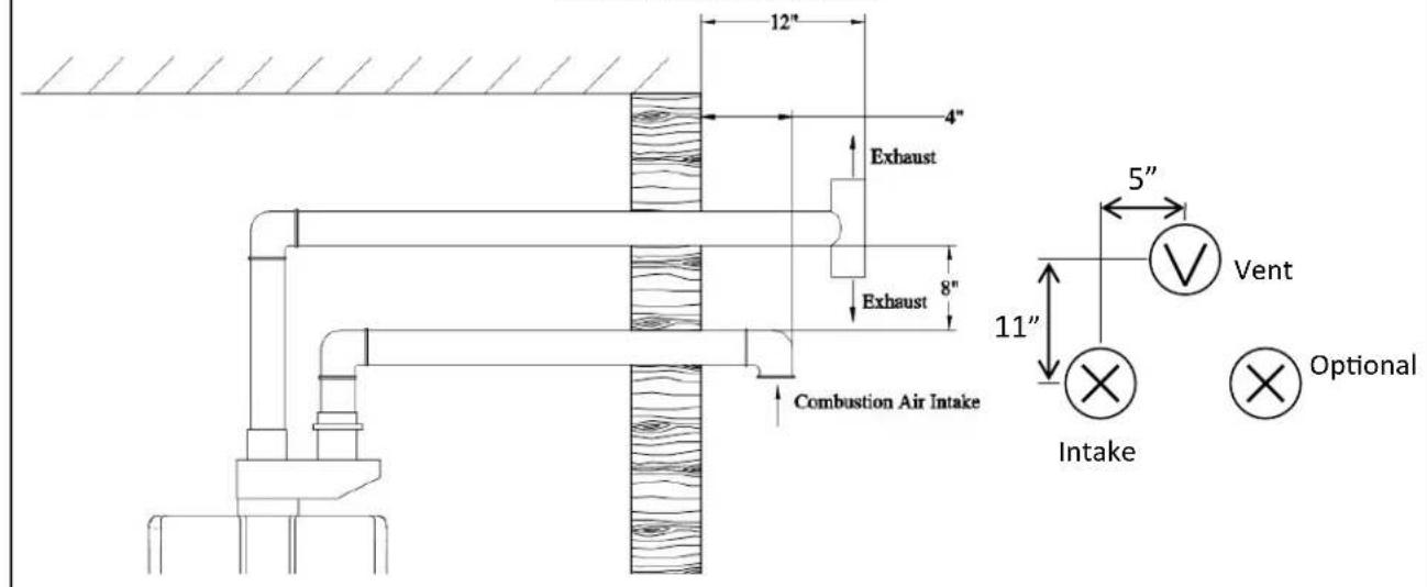
PVC/CPVC Sidewall (Tee and Snorkel) Terminations:
Locate the vent and intake air termination using the following guidelines:
- The total length of the vent or intake air piping must not exceed the limits given in maximum equivalent vent length tables. The equivalent length for 90irc elbows and termination associated with the respective vent and intake air piping arrangement MUST be subtracted from total length listed in maximum equivalent vent tables.
- Specific to Side Wall Tee Termination, the vent and intake air piping must terminate at the outside surface of the outer wall, minimum 1" between wall, tee, and elbow socket ends.
- Termination must be installed a minimum of 12 (30.5 cm), above grade or anticipated snow level.
- Refer to 'Vent Termination Clearances' table for recommended exhaust/combustion terminal position.
NOTE
If the vent is terminated on a sidewall that is subject to high winds it is recommended to terminate the vent using a tee. A tee provides the best protection against wind.
5. The intake air pipe must terminate away from the vent termination. Both vent and air intake pipe terminations must be installed a minimum of 12 (30.5 cm) above grade or highest anticipated snow level and as shown in figures to the right.

NOTICE
The information and figures depicting method of terminating the vent and combustion air intake pipes are directly related to PVC/CPVC vent systems. When utilizing a method other than a PVC/CPVC vent system there may be some variations. Consult the respective vent manufacturer or the water heater manual for recommendations and clarifications.

NOTICE
Slope horizontal exhaust piping downward toward the water heater a minimum of 1/4 inch per foot. DO NOT slope combustion air piping down towards water heater. Dispose of condensate per local codes.
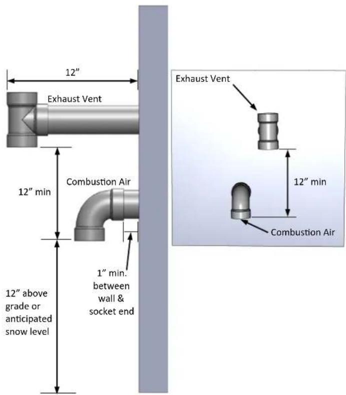
Sidewall Vent and Combustion Air Piping with Tee Termination

Sidewall Vent and Combustion Air Piping with Snorkel Termination
(Picture shown is for illustration purposes only; listed equivalent length is based on worst case scenario of 3 × 90irc Elbows or 15 equivalent feet.)
Certified PVC/CPVC Vent Termination Options (continued)
NOTE
All figures shown in this section are in reference to flat roofs. For heights of venting passing through a pitched roof, refer to NFPA 54/ANSI Z223.1-09 (table and figure 12.7.2), CSA B149.1-10 (figure 8.1) Pitched Roof Termination Clearances Diagram (this manual)
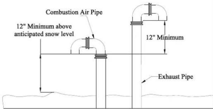
PVC/CPVC Roof (Tee and upside down "U") Terminations:
Locate the vent and intake air termination using the following guidelines:
- The total length of the vent or intake air piping must not exceed the limits given in maximum equivalent vent length tables. The equivalent length for 90irc elbows and termination associated with the respective vent and intake air piping arrangement MUST be subtracted from the total length listed in maximum equivalent vent length tables.
- For roof terminations installed as shown in the figures to the right, the intake air piping must terminate using a tee or combination of elbows. The termination must be installed 12 (30.5 cm) above roof or the highest anticipated snow level.
- The vent must terminate vertically with a coupling to facilitate the bird screen and must be located 12 (30.5 cm) minimum above the combustion air inlet.
- The vent and intake air terminations must be located a radial distance of 12 minimum (30.5 cm) from outer wall of vent termination to outer wall of combustion air intake termination.

Vertical Termination of Tee-Vent and Combustion Air Pipe

Vertical Termination of U-Vent and Combustion Air Pipe
Multiple Water Heater Installation - Through the Roof
Locate the vent and intake air termination using the following guidelines:
- For installations with multiple Tankless Water Heaters, refer to Figure 16 for proper exhaust and combustion air piping placement.
- Roof penetration of the vent and intake air piping should be such that the combustion air intake is a minimum 12 (30.5 cm) from the adjacent vent pipe of the other water heater. For installations in the U.S. refer to Figure 16. For installations in Canada, refer to clearances required by CAN/CSA B149.1.

Vertical Termination of Multiple Water Heaters
Certified PVC/CPVC Vent Termination Options (continued)
NOTE
To prevent the possibility of condensate freeze-up, do not install vent kits one above the other. Once the vent terminal location has been determined, make holes through the exterior wall to accommodate the vent pipes. Vent pipes must exit exterior wall horizontally only.

Pitched Roof Termination Clearances:
Vertical Termination of U-Vent and Combustion Air Pipe on a Pitched Roof
NOTE
DO NOT use lubricant between two PVC/CPVC components. Refer to cement manufacturer instruction for specific instructions and handling.
Basic Instructions for Cementing Joints:
- Cut pipe end square; smooth out jagged edges and burrs. Chamfer end of pipe; then clean fitting socket and pipe joint area of all dirt, grease, or moisture.
-
After checking pipe and socket for proper fit, wipe socket and pipe with cleaner-primer. Apply a liberal coat of primer to inside surface of socket and outside of pipe.
-
Apply a thin coat of cement evenly in the socket. Quickly apply a heavy coat of cement to the pipe and insert pipe into fitting with a slight twisting motion until it bottoms out.
- Hold the pipe fitting for 30 seconds to prevent the tapered socket from pushing the pipe out of the fitting.
- Wipe all excess cement from the joint with a rag. Allow 15 minutes before handling. Cure time will vary according to fit, temperature, and humidity
Parts Information
| Types of Acceptable PVC/CPVC Elbows for Venting System | ||
| ACCEPTABLE | ACCEPTABLE | NOT ACCEPTABLE |
| 90° Elbows, Female Unthreaded Socket Ends: (Long Turn) Long Sweep | 90° Elbows, Female Unthreaded Socket Ends: (1/4 Bend) Short Sweep | 90° Elbows, Female Unthreaded Socket Ends: Close Turn |
WARNING
Improper installation of vent system and components, or failure to follow all installation instructions, can result in property damage, personal injury, or death.
Parts Information (continued)
Vent Components and Assigned Equivalent Lengths:
The following fittings and accessories (by others) are certified for use with the abovementioned condensing products:
| Approved PVC/CPVC Termination Components | ||||
| OEM | OEM # or Cert. | Product Description | Diagram | Equivalent Lengths (Ft.) |
| IPEX (Purchased separately) | 196006 /197009 (3 Inch)196021 /197021 (4 Inch)(System 636) | PVC/CPVC-FGVConcentric Vent Kit w/vent screen | 20 | |
| IPEX (Purchased separately) | 196985(3 Inch)196986(4 Inch)(System 636) | Low ProfileTermination Kit | 5 | |
| Field Supplied PVC/CPVC Sch. 40Fittings or Approved Equal | Comply withCAN/CGAB149.1 & ULC-S636 | 3" and 4" SCH 40 (SolidCore) PVC/CPVC TEEw/vent screen | 5 | |
| Field Supplied PVC/CPVC Sch. 40Fittings or Approved Equal | Comply withCAN/CGAB149.1 & ULC-S636 | 3" and 4" SCH 40 (SolidCore) PVC/CPVC 90° ELw/vent screen | 5 | |
| Field Supplied PVC/CPVC Sch. 40Fittings or Approved Equal | Comply withCAN/CGAB149.1 & ULC-S636 | 3" and 4" SCH 40 (SolidCore) PVC/CPVC 45° ELw/vent screen | 2.5 | |
| IPEX (Purchased separately) | 196051(3 Inch)196052(4 Inch) | Friction fit vent screen(3" and 4") | 0 | |
| Field Supplied PVC/CPVC Sch. 40Fittings or Approved Equal | Comply withCAN/CGAB149.1 & ULC-S636 | 3" and 4" SCH 40 (SolidCore) PVC/CPVSnsorkel vent w/vent screen(2X90° or2X90° EL + 1X45° EL) | 15 | |
- Vent screens are not ULC S636 Certified.
Friction fit vent screens inside termination fitting are used to avoid debris and/or small animals from entering vent. - Primer shall be used when installing System 636® and other PVC/CPVC products at temperatures below 32 irc F( 0 irc C) .
- Primer is required in some jurisdictions regardless of temperature, verify with your local authority having jurisdiction.
- Use only System 636 cements and primers; substituting other cements and primers will void IPEX's certification and warranty; (see OEM's literature).
For Schedule 40 PVC/CPVC, any glue and primer approved by your local authority having jurisdiction may be substituted.
KCM Series Manual 35
PVC/CPVC Equivalent Vent Length Calculation Sheet
| Equivalent Vent Length Calculation Sheet | ||||
| Fitting / Termination Type | Number of fittings | Equivalent Vent Length | Total Equivalent Length | |
| 1) 90 elbow | x | 5 | = | |
| 2) 45 elbow | x | 2.5 | = | |
| 3) IPEX Low Profile Termination | x | 5 | = | |
| 4) IPEX 4" Concentric Termination | x | 20 | = | |
| 5) IPEX 3" Concentric Termination | x | 20 | = | |
| 6) 3" Tee Termination | x | 5 | = | |
| 7) 4" Tee Termination | x | 5 | = | |
| 8) 3" Snorkel Termination | x | 15 | = | |
| 9) 4" Snorkel Termination | x | 15 | = | |
| 10) Length of Straight Section in feet | NA | Total (add up lines 1 through | ||
Note: Ensure SW 1 in DIPSW 1 is in "OFF" position if vent length is greater than 21ft (6.4m).
Condensate
Condensate can form in high efficiency direct vent appliances. Without proper drainage, condensate will damage the heat exchanger.
To prevent condensate damage, follow these instructions.
DO NOT
- Do not connect the condensate drain pipe directly to the rain sewer.
- Do not connect the condensate drain line with an air conditioning evaporator coil drain.
MUST DO
- Use only venting that is approved and identified as acceptable for your particular model.
- Slope the venting toward the appliance according to the vent manufacturer's installation instructions.
- All condensate must drain and be disposed of according to local codes.
- Use only corrosion resistant materials for the condensate drain lines such as PVC pipe or plastic hose.
- The condensate drain pipe (along its entire length) must be at least the same diameter as the drain line, (1/2 inch NPT).
- The end of the condensate drain pipe should be open to the atmosphere. The end should not be under water or other substances.
- To minimize freezing of the condensate in outdoor units, run the condensate drain line through an interior wall or between insulation and an interior wall.
- It is recommended that the condensate trap drain line be insulated. A frozen condensate trap results in a diagnostic code 25.
INFORMATION
Water heaters have an integrated condensate collector.
- Regions of cold climate will create more condensate in the vent system.
- The condensate drain pipe should be as short as possible and have a downward pitch.
- If the condensate drain gets blocked, a diagnostic code will display on the controller or status monitor. If this occurs, the condensate drain must be cleaned.
- The condensate trap will automatically prime (self-prime) during operation of the unit as condensate forms. Condensate draining from the unit indicates that the trap is full and that there is no blockage in the condensate drain. It is not necessary to add water to the condensate trap.
- A condensate neutralizer kit, 804000074, is available from Rinnai. The kit allows condensate to flow through neutralizing media that raises the pH of the condensate to a level that will help prevent corrosion of the drain and public sewer system.
Checklist for Venting and Condensate (indoor models only)
Verify proper clearances around the vents and air intakes.
For indoor models, ensure SW4 in DIPSW2 is set to the appropriate venting style.
- Ensure you have used the correct venting products for the model installed and that you have completely followed the venting manufacturer's installation instructions and these installation instructions.
Verify that the vent system does not exceed the maximum length for the number of elbows used.
Installation of Plumbing
Pressure Relief Valve Requirements
A pressure relief valve must be installed according to these instructions.
An approved pressure relief valve is required by the American National Standard (ANSI Z21.10.3) for all water heating systems and shall be accessible for servicing.
DO NOT
- Do not plug the relief valve and do not install any reducing fittings or other restrictions in the relief line. The relief line should allow for complete drainage of the valve and the line.
- Do not place any other type valve or shutoff device between the relief valve and the water heater.
MUST DO
- The relief valve must comply with the standard for Relief Valves and Automatic Gas Shutoff Devices for Hot Water Supply Systems ANSI Z21.22 and/or the standard Temperature, Pressure, Temperature and Pressure Relief Valves and Vacuum Relief Valves, CAN1-4.4.
- The relief valve must be rated up to 150 psi and to at least the maximum BTU/hr of the appliance.
- The discharge from the pressure relief valve should be piped to the ground or into a drain system per local codes.
- The pressure relief valve must be manually operated once a year to check for correct operation.

WARNING
Water discharged from the pressure relief valve could cause severe burns instantly or death from scalds.
- The relief valve should be added to the hot water outlet line and near the hot water outlet according to the manufacturer's instructions. DO NOT place any other type valve or shut off device between the relief valve and the water heater.
INFORMATION
- If a relief valve discharges periodically, this may be due to thermal expansion in a closed water supply system. Contact the water supplier or local plumbing inspector on how to correct this situation. Do not plug the relief valve.
- The American National Standard (ANSI Z21.10.3) does not require a combination temperature and pressure relief valve for this appliance. However, local codes may require a combination temperature and pressure relief valve.
Isolation Valves
Rinnai strongly recommends the installation of isolation valves on the cold and hot water lines because they provide the ability to isolate the water heater from the structure's plumbing and allow quick access to flush the heat exchanger. Flushing the heat exchanger regularly is required as part of the proper maintenance for this water heater.
Piping Requirements
A manual water control valve must be placed in the water inlet connection to the water heater before it is connected to the water line. Unions may be used on both the hot and cold water lines for future servicing and disconnection of the unit.
DO NOT
- Do not introduce toxic chemicals such as those used for boiler water treatment to the potable water used for space heating.
MUST DO
- The piping (including soldering materials) and components connected to this appliance must be approved for use in potable water systems.
- Purge the water line to remove all debris and air. Debris will damage the water heater.
- If the appliance will be used as a potable water source, it must not be connected to a system that was previously used with a non-potable water heating appliance.
- Ensure that the water filter on the water heater is clean and installed.
Isolation Valves and Pressure Relief Valve (PRV)
The isolation valves provide the ability to isolate the water heater from the structure's plumbing and allow quick access to flush the heat exchanger. Check with local codes to determine if a pressure and temperature relief valve is required. The valves must meet American National Standard (ANSI Z21.10.3) / Canadian Standard (CSA 4.3) and are ANSI/NSF 61 approved for potable water.
Isolation Valves Installation Instructions:
NOTICE
When unscrewing the UNION FITTING, Be careful not to lose any washers and/or gaskets that may be present.
- Wrap the ends of the threaded water inlet and outlet on the tankless water heater, as well as the threaded end of the approved pressure relief valve with a minimum of 5 wraps of Teflon® tape.
- Screw the pressure relief valve into the 3/4'' threads opposite the wing handle on the HOT water service valve. (RED drain handle) (see Pressure Relief Valve Section for proper installation requirements)
- Loosen the 3/4'' union nut on the HOT water valve and connect to the HOT water outlet on the tankless water heater. If nut is removed, ensure that you realign the tailpiece accurately to the valve and that the black washer is positioned such that the raised metal edge of the valve is inside the washer.
- Align the direction of the HOT water drain to the desired position.
- Tighten the union assembly to the HOT water valve using approximately 15 foot lbs of torque.
- Repeat steps 3-5 for the COLD water valve. (BLUE drain handle) for connection to the COLD water inlet on the tankless water heater.
- Connect the INLET on the COLD water valve to the MAIN SOURCE of the water supply.
- Connect the OUTLET on the HOT water valve to the HOT WATER plumbing system.
- Ensure that both drain valve lever handles are in the closed position (perpendicular to the drain portion of the body).
KCM Series Manual 39
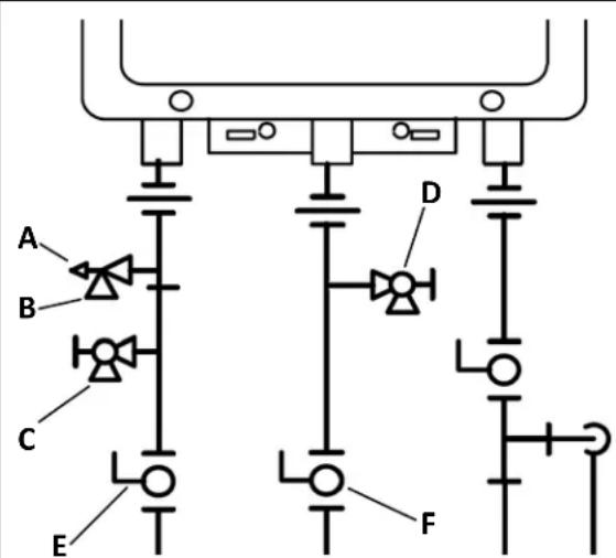
A Pressure Relief Valve (PRV)
B PRV Discharge Outlet
C Hot Drain Valve
D Cold Drain Valve
E Hot Ball Valve
F Cold Ball Valve
*Not Included
Pressure Relief Valve Installation Instructions:
The PRV must be connected to the 3/4'' threaded port on the HOT (RED) water service valve (will be adjacent to or above the shut off, never below). Installation must maintain a 3/4'' port size with no shut off valve or line restriction in-between the appliance and the PRV. The discharge line from the PRV should pitch downward and terminate 6'' above drains where discharge will be clearly visible. The discharge end of the line shall be plain (unthreaded) and a minimum of 3/4'' in diameter. The discharge line material must be suitable for water at least 180irc Fahrenheit. No valve of any type may be installed in the discharge line of the pressure relief valve.
Pressure Relief Valve Maintenance:
For proper care of this approved pressure relief valve, it is recommended that the valve is manually operated once a year. In doing so, it will be necessary to take precautions with regard to the discharge of potentially scalding hot water under pressure. Ensure discharge water has a safe place to flow. Contact may cause property damage and/or bodily harm.
Please note PRV must be rated for up to 150 psi and at least the maximum BTU/hr of the appliance.
Piping Diagram for Basic Installation

| KEY | This is not an engineered drawing. It is intended only as a guide and not as a replacement for professionally engineered project drawings. This drawing is not intended to describe a complete system. It is up to the contractor/engineer to determine the necessary components and configuration of the particular system being installed. This drawing does not imply compliance with local building code requirements. It is the responsibility of the contractor/engineer to ensure installation is in accordance with all local building codes. Confer with local building officials before installation. | ||
| 15 | 3/4" Ball Valve | Pressure Regulator | |
| = | 3/4" Union | Circulating Pump | |
| Check Valve | Boiler Drain Valve | ||
| Pressure Relief Valve | Solenoid Valve | ||
Connect Water Heater to Water Supply
Water connections to the tankless water heater should follow all state and local plumbing codes.
If this is a standard installation, refer to the Piping Diagram for Basic Installation.
- Plumb water supply to the tankless water heater on the 3/4'' MNPT connection at the bottom of the unit marked "Water Inlet", which is the cold water supply.
- Plumb the building hot water supply to the 3/4'' MSPT connection marked "Water Outlet", which is the hot water supply.
If a pipe cover will be installed, make sure water lines to the water heater fit.
Checklist for Plumbing
- Purge the water line of all debris and air by closing the hot isolation valve and opening the cold isolation valve and its drain. Debris will damage the water heater. Use a bucket or hose if necessary.
Ensure that hot and cold water lines are not crossed to the unit and are leak free.
Ensure that a pressure relief valve is properly installed with a rating that exceeds the BTU input of the water heater model. Refer to the rating plate on the side of the water heater for BTU input.
Clean the inlet water filter by closing the cold and hot water inlet isolation (shut-off) valves. Put a bucket under the filter at the bottom of the water heater to catch any water that is contained inside the unit. Unscrew the water filter. Rinse the filter to remove any debris. Install the filter and open the isolation valves.
Check for proper water pressure to the water heater. Minimum water pressure is 50 psi. Rinnai recommends 60-80 psi for maximum performance.
Ensure any issues regarding water quality have been properly addressed.
Installation of Gas Supply
WARNING
- A licensed professional must install the gas supply.
- Turn off 120v power supply.
- Turn off the gas.
- Gas is flammable. Do not smoke or provide other ignition sources while working with gas.
- Do not turn on the water heater or gas until all fumes are gone.
General Instructions
MUST DO
- A manual gas control valve must be placed in the gas supply line to the water heater. A union can be used on the connection above the shut off valve for the future servicing or disconnection of the unit.
- Check the type of gas and the gas inlet pressure before connecting the water heater. If the water heater is not of the gas type that the building is supplied with, DO NOT connect the water heater. Contact the dealer for the proper unit to match the gas type.
- Check the gas supply pressure immediately upstream at a location provided by the gas company. Supplied gas pressure must be within the limits shown in the Specifications section of this manual with all gas appliances operating.
- Before placing the appliance in operation, all joints including the heater must be checked for gas tightness by means of leak detector solution, soap and water, or an equivalent nonflammable solution, as applicable. (Since some leak test solutions, including soap and water, may cause corrosion or stress cracking, the piping shall be rinsed with water after testing, unless it has been determined that the leak test solution is non-corrosive.)
-
Use approved connectors to connect the unit to the gas line. Purge the gas line of any debris before connection to the water heater.
-
Any compound used on the threaded joint of the gas piping shall be a type that resists the action of liquefied petroleum gas (propane / LPG).
- The gas supply line shall be gas tight, sized, and so installed as to provide a supply of gas sufficient to meet the maximum demand of the heater and all other gas consuming appliances at the location without loss of pressure.
INFORMATION
- If in doubt about the size of the gas line, refer to an approved pipe sizing chart
Size the gas pipe
The gas supply must be capable of handling the entire gas load required at the location. Gas line sizing is based on gas type, the pressure drop in the system, the gas pressure supplied, and gas line type. For gas pipe sizing in the United States, refer to the National Fuel Gas Code, NFPA 54. The below information is provided as an example. The appropriate table from the applicable code must be used.
- For some tables, you will need to determine the cubic feet per hour of gas required by dividing the gas input by the heating value of the gas (available from the local gas company). The gas input needs to include all gas products at the location and the maximum BTU usage at full load when all gas products are in use.
- Use the table for your gas type and pipe type to
Cubic Feet Gas Input of all gas products (BTU / HR) per Hour = Heating Value of Gas (BTU / FT³) (CFH)
find the pipe size required. The pipe size must be able to provide the required cubic feet per hour of gas or the required BTU/hour.
Example:
The heating value of natural gas for your location is 1000 BTU/FT 3 . The gas input of the RUCS75i is 160,000 BTU/HR. Additional appliances at the location require 65,000 BTU/hr. Therefore the cubic feet per hour = (160,000 + 65,000) / 1000 = 165 FT 3 /HR. If the pipe length is 10 feet then the 3/4 inch pipe size is capable of supplying 264 FT 3 /HR of natural gas.
Pipe Sizing Table - Natural Gas
Schedule 40 Metallic Pipe
Inlet Pressure: less than 2 psi (55 inches W.C.)
Pressure Drop: 0.3 inches W.C.
Specific Gravity: 0.60
cubic feet per hour
| Length | Pipe Size (inches) | |||
| 3/4 | 1 | 1 1/4 | 1 1/2 | |
| 10 | 273 | 514 | 1060 | 1580 |
| 20 | 188 | 353 | 726 | 1090 |
| 30 | 151 | 284 | 583 | 873 |
| 40 | 129 | 243 | 499 | 747 |
| 50 | 114 | 215 | 442 | 662 |
| 60 | 104 | 195 | 400 | 600 |
| 70 | 95 | 179 | 368 | 552 |
| 80 | 89 | 167 | 343 | 514 |
| 90 | 83 | 157 | 322 | 482 |
| 100 | 79 | 148 | 304 | 455 |
Pipe Sizing Table - Propane Gas
Schedule 40 Metallic Pipe
Inlet Pressure: 11.0 inches W.C.
Pressure Drop: 0.5 inches W.C.
Specific Gravity: 1.50
Capacity in Thousands of BTU per Hour
| Length | Pipe Size (inches) | |||
| 1/2 | 3/4 | 1 | 1 1/4 | |
| 10 | 291 | 608 | 1150 | 2350 |
| 20 | 200 | 418 | 787 | 1620 |
| 30 | 160 | 336 | 632 | 1300 |
| 40 | 137 | 287 | 541 | 1110 |
| 50 | 122 | 255 | 480 | 985 |
| 60 | 110 | 231 | 434 | 892 |
| 80 | 101 | 212 | 400 | 821 |
| 100 | 94 | 197 | 372 | 763 |
Connect Electricity

WARNING
Do not use an extension cord or an adapter plug with this appliance.
The water heater must be electrically grounded in accordance with local codes and ordinances or, in the absence of local codes, in accordance with the National Electrical Code, ANSI/NFPA No. 70.
Indoor water heaters are equipped with a three-prong (grounding) plug for your protection against shock hazard and should be plugged directly into a properly grounded three-prong receptacle. Do not cut or remove the grounding terminal from this plug.
Do not rely on the gas or water piping to ground the water heater. A screw is provided in the junction box for the grounding connection.
The water heater requires 120 VAC, 60Hz power from a properly grounded circuit.
If using the 5 foot long power cord, plug it into a standard 3 prong 120 VAC, 60Hz properly grounded wall outlet.
On outdoor models, a disconnect switch must be provided and installed for the incoming 120 VAC power. It should be a type that is suitable for outdoor use. Check the National Electrical Code, ANSI/NFPA 70 and your local codes for a proper switch type to use in your area.
The wiring diagram is located on the Technical Sheet attached to the inside of the front cover.
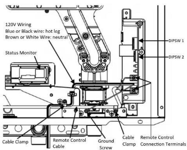
Adjustment for High Altitude Installations
Set SW3 in DIPSW 1 to the values shown in table below for your altitude. The default setting for the appliance is 0-2000 ft (0-610 m) with switches SW3 in the OFF position.
When the DIP switch is adjusted, it is not necessary to adjust the gas pressure setting for high altitude.
| Altitude SW3 in DIPS | W 1 |
| 0-2000 ft (0-610 m) | OFF |
| 2001-5400 ft (610-1646 m) | ON |
Adjustment for Vent Length (indoor models only)
Adjust SW 1 in DIPSW 1 if required. Refer to the section "Maximum vent length".
Checklist for Gas and Electricity
A manual gas control valve is placed in the gas line to the water heater.
Check the gas lines and connections for leaks.
- Confirm that the gas inlet pressure is within limits.
- Confirm that the water heater is rated for the gas type supplied.
- Confirm that the electricity is supplied from 120 VAC, 60Hz power source and is in a properly grounded circuit.
- Confirm that an extension cord or an adapter plug has NOT been used with the water heater.
Installation of Optional Temperature Controller

WARNING
Turn the power off. Do not attempt to connect the temperature controller(s) with the power on. Although the controller is a low voltage device, there is 120 volt potential next to the temperature controller connections inside the unit.
Do not connect the temperature controller to the 120VAC terminals provided for the optional solenoid drain valves.
The units referenced in this manual do not include a temperature controller.
Controller Location
- The controller should be out of reach of small children.
- Avoid locations where the controller may become hot (near an oven or radiant heater).
- Avoid locations in direct sunlight. The digital display may be difficult to read in direct sunlight.
- Avoid locations where the temperature controller could be splashed with liquids.
- Do not install in locations where the controller can be adjusted by the public.
Cable Lengths and Sizes
The cable for the temperature controller should be a non-polarized two-core cable with a minimum gauge of 22 AWG. The maximum cable length from each controller to the water heater depends on the total number of wired controllers connected to the water heater.
| Number of Wired Controllers | Maximum Cable Length for each Controller to Water Heater |
| 1 328 ft (100 m) | |
| 2 164 ft (50 m) | |
| 3 or 4 65 ft (20 m) |
Configurations
A maximum of 4 temperature controllers can be installed for a water heater or bank of water heaters. Controllers can only be wired in parallel. Controllers cannot be wired in series.
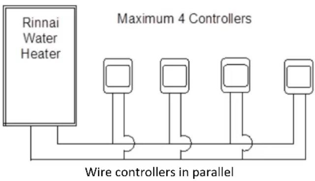
The 4 temperature controllers can consist of multiple MC-91-2.
(MC-91-1 should not be installed on a unit that already has an MC-91-2 connected)
If 4 MC-91-2's are installed, simultaneously press the Priority and On/Off buttons on the fourth controller until a beep sounds.
Do not install MC-100V and BC-100V.
Mounting the controller
- Make three holes in the wall as shown.
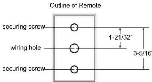
- Run the cable between the controller and the water heater or the controller and another controller.
- Remove the face plate from the temperature controller using a screwdriver.
- Connect the cable to the temperature controller.
- Mount the controller to the wall using the holes drilled in step 1.
- Disconnect the power from the water heater.
- Remove the plastic cover from the PCB and electrical connections.
- Thread the cable through the access hole at the base of the unit and connect the wires to the controller terminals on the right hand side bottom of the PCB.
- Secure the controller cable using the clamp provided.
- Replace plastic cover over PCB and then replace the cover of the water heater.
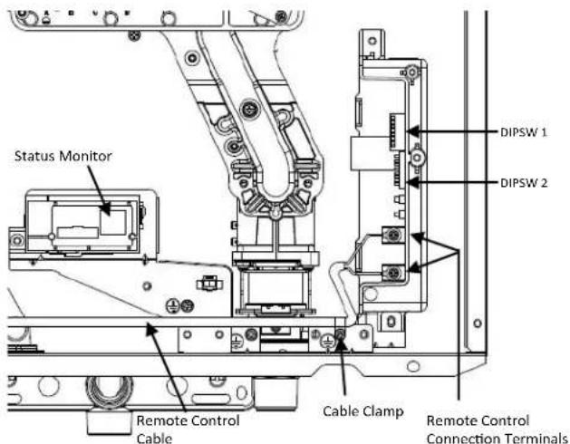

Once Installation is complete, install the front panel and cycle the unit on to ensure it is functioning correctly. Proper installation/operation of the unit is with the front panel installed.
Final Checklist
The water heater is not subject to corrosive compounds in the air.
Water supply does not contain chemicals or exceed total hardness referenced in manual.
Clearances from the water heater unit are met.
Clearances from vent termination are met.
For indoor models, ensure you have used the correct venting products for the model installed and that you have completely followed the venting manufacturer's installation instructions and these installation instructions.
For indoor models, verify that the vent system does not exceed the maximum length for the number of elbows used.
For indoor models, verify that SW 1 in DIPSW 1 has been adjusted for vent length if necessary. Refer to the section on Maximum Vent Length.
For indoor models, ensure SW4 in DIPSW 2 is set to the appropriate venting style.
Purge water line of all debris and air by closing hot isolation valve and opening the cold isolation valve and its drain. Debris will damage the water heater. Use a bucket or hose if necessary.
Ensure that hot and cold water lines are not crossed to the unit and are leak free.
A manual gas control valve has been placed in the gas line to the water heater.
Ensure a pressure relief valve is properly installed with a rating that exceeds the BTU input of the water heater model. Refer to the rating plate on the side of the water heater for BTU input.
Clean the inlet water filter by closing the cold and hot water inlet isolation (shut-off) valves. Put a bucket under the filter at the bottom of the water heater to catch any water that is contained inside the unit. Unscrew the water filter. Rinse the filter to remove any debris. Install the filter and open the isolation valves.
Check the gas lines and connections for leaks.
- Confirm that the gas inlet pressure is within limits.
- Confirm that the water heater is rated for the gas type supplied.
Confirm that the electricity is supplied from a 120 VAC, 60Hz power source, is in a properly grounded circuit, and turned on. - Verify the temperature controller or status monitor is functioning properly.
Verify that SW3 in DIPSW 1 is set correctly for your altitude.
Verify the system is functioning correctly by connecting your manometer to the gas pressure test port on the water heater. Operate all gas appliances in the home or facility at high fire. The inlet gas pressure at the water heater must not drop below that listed on the rating plate.
DO NOT introduce toxic chemicals such as those used for boiler water treatment to the potable water used for space heating.
If the water heater is not needed for immediate use, drain the water from the heat exchanger.
Install the front panel.
Explain to the customer the importance of not blocking the vent termination or air intake.
Explain to the customer the operation of the water heater, safety guidelines, maintenance, and warranty.
The installation must conform with local codes or, in the absence of local codes, with the National Fuel Gas Code, ANSI Z223.1/NFPA 54, or the Natural Gas and Propane Installation Code, CSA B149.1. If installed in a manufactured home, the installation must conform with the Manufactured Home Construction and Safety Standard, Title 24 CFR, Part 3280 and/or CAN/SCA Z240 MH Series, Mobile Homes.
Inform the consumer if the isolation valves are not installed or if a water softening system is not installed.
Leave the entire manual taped to the water heater (indoor units) or give the entire manual directly to the consumer.
Technical Data
Specifications
| RUCS65i | RUCS75i | RUS65e | RUS75e | ||
| Minimum Gas Consumption Btu/h 10,300 | |||||
| Maximum Gas Consumption Btu/h | 130,000 | 160,000 | 130,000 | 160,000 | |
| Hot water capacity (Min - Max) * | 0.26 - 6.5 GPM(1.0 - 25.7 L/min) | 0.26 - 7.5 GPM(1.0 - 28.7 L/min) | 0.26 - 6.5 GPM(1.0 - 25.7 L/min) | 0.26 - 7.5 GPM(1.0 - 28.7 L/min) | |
| Temperature Setting (no controller) | 120° F (49°C), 125° F (52°C), 135° F (57°C), 140° F (60°C) | ||||
| Maximum Temp Setting 140° F (60°C) | |||||
| Minimum Temperature Setting | 120° F (49°C) | ||||
| Weight | 57.3 lb (26 kg) | ||||
| Noise level | 47 dB | 55 dB | |||
| Electrical Data | Normal | 89 W | 61 W | ||
| Standby | 1.3 W | ||||
| Anti-frost Protection | 167 W | 140W | |||
| Max Current | 2.3 A | ||||
| Fuse | 10 A | ||||
| Gas Supply Pressure | Natural Gas | 4.0 - 10.5 inch W.C. | |||
| Propane | 8.0 - 13.5 inch W.C. | ||||
| By-Pass Control | Fixed | ||||
| Type of Appliance | Condensing, Tankless, Temperature controlled continuous flow gas hot water system | ||||
| Connections | Gas Supply: 3/4" MNPT, Cold Water Inlet: 3/4" MNPT, Hot Water Outlet: 3/4" MNPT | ||||
| Ignition System | Direct Electronic Ignition | ||||
| Electric Connections | Appliance: AC 120 Volts, 60Hz.Temperature Controller: DC 12 Volts (Digital) | ||||
| Water Temperature Control | Simulation Feed forward and Feedback | ||||
| Water Supply Pressure | Minimum Water Pressure: 50 PSI (Recommended 60-80 PSI for maximum performance) | ||||
| Maximum Water Supply Pressure | 150 PSI | ||||
| Remote Control Cable | Non-Polarized Two Core Cable (Minimum 22 AWG) | ||||
| Energy Star Qualified | Yes | ||||
| Certified for installation in manufactured(mobile) homes | Yes | ||||
| Complies with South Coast Air QualityManagement District 14 ng/J or 20 ppm NOxemission levels | Yes | ||||
- Minimum flow may vary slightly depending on the temperature setting and the inlet water temperature. Minimum activation flow is 0.4 GPM (1.5 L/min).
Our products are continually being updated; therefore, specifications are subject to change without prior notice.
The maximum inlet gas pressure must not exceed the value specified by the manufacturer. The minimum value listed is for the purpose of input adjustment.
Dimensions
Inches (millimeters)
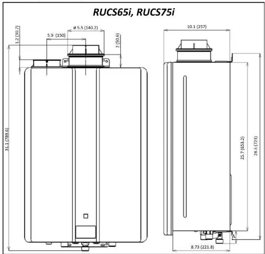
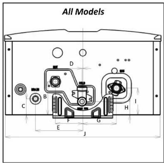
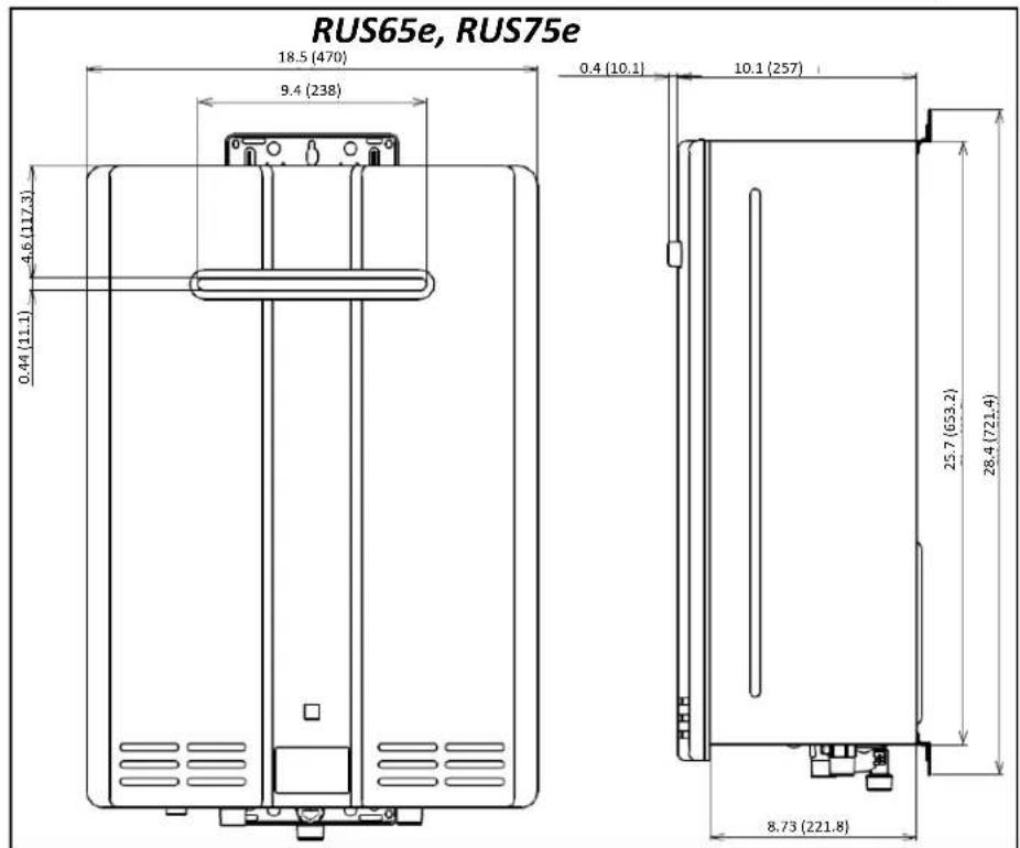
* This is the minimum dimension from the wall. The wall bracket is adjustable to allow an additional 1.3 inches (33 mm).
| DIMENSION Inches (mm) | |
| A (GAS) 1.3 (33.2) | |
| A (COLD) 1.93 (49) | |
| A (HOT) 1.35 (34.4) | |
| A (CONDENSATE OUTLET) | 0.94 (23.9) |
| B 3.93 (100) | |
| C 1.91 (48.6) | |
| D 0.09 (2.2) | |
| E 5.6 (142.3) | |
| F 3.24 (82.4) | |
| G 3.99 (101.4) | |
| H 1.58 (40.1) | |
| I 3.17 (80.4) | |
| J 18.3 (466) |
Pressure Drop and Water Flow Curves
RUCS65i,
RUS65e
RUCS75i,
RUS75e

NOTICE
The chart below only applies to incoming water temperatures of 70ircF (21ircC) or less. For incoming water temperatures greater than 70ircF (21ircC) please contact Rinnai.
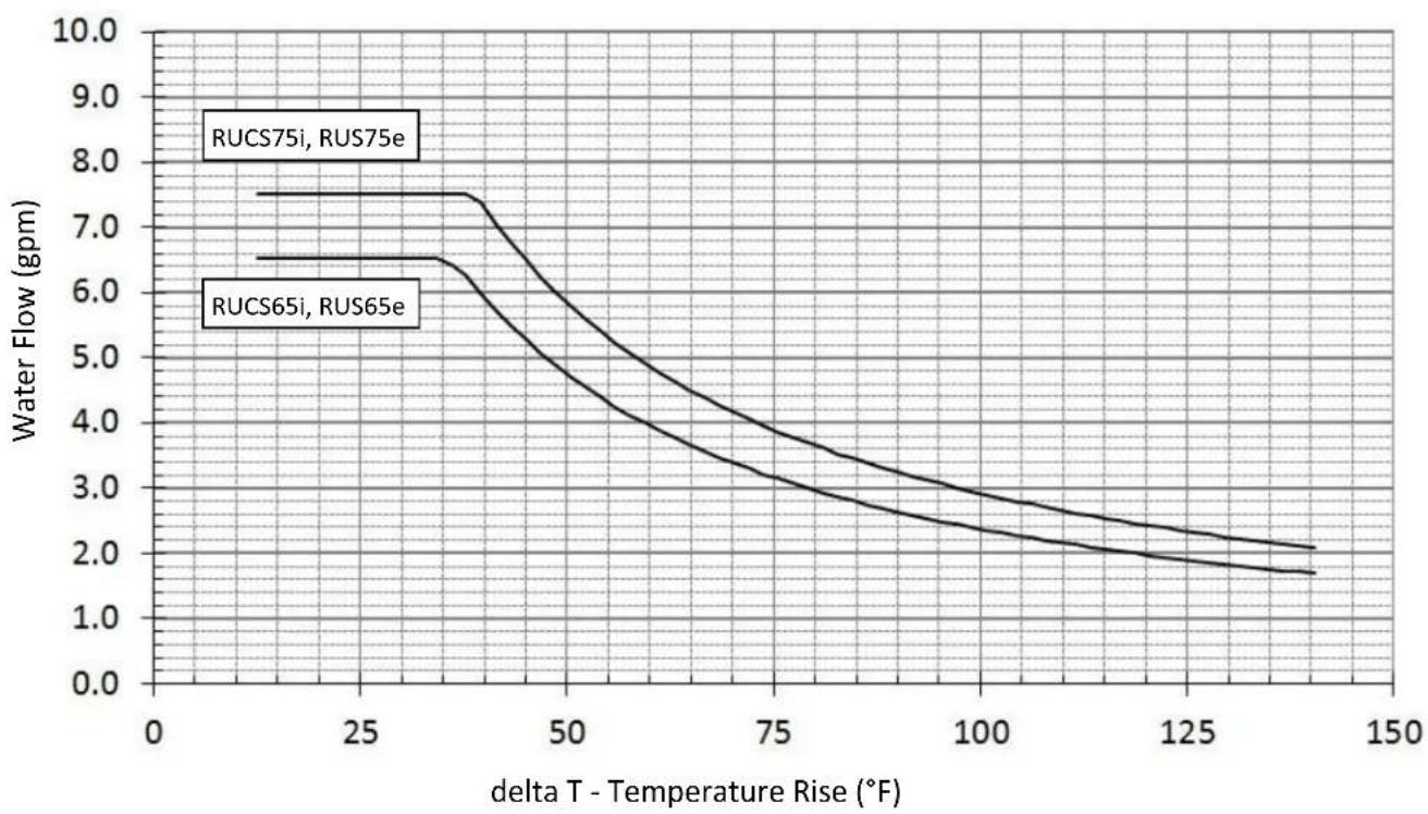
Ladder Diagram

Rinnai
Direct Vent Tankless Water Heater Operation Instructions
FOR INDOOR APPLICATIONS ONLY
RUCS65i REU-KCM2025FFU-US
RUCS75i... REU-KCM2528FFU-US
FOR OUTDOOR APPLICATIONS ONLY
RUS65e . REU-KCM2025W-US
RUS75e REU-KCM2528W-US
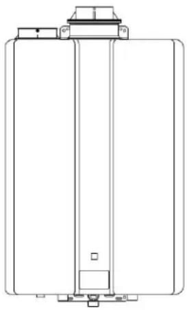
Important Facts about your Water Heater
Thank you for purchasing a Rinnai Tankless Water Heater. For proper operation and safety, it is important to follow the instructions and adhere to all safety precautions.
Read all of the instructions and the warranty thoroughly before operating this water heater. Keep this manual in a safe place.
NOTICE: Rinnai sometimes shares customer contact information with businesses that we believe provide products or services that may be useful to you. By providing this information, you agree that we can share your contact information for this purpose. If you prefer not to have your information shared with these businesses, please contact customer service and ask not to have your information shared. We will however, continue to contact you with information relevant to the product(s) you registered and/or you account with us.

WARNING
If the information in these instructions is not followed exactly, a fire or explosion may result causing property damage, personal injury, or death.
-
Do not store or use gasoline or other flammable vapors and liquids in the vicinity of this or any other appliance.
WHAT TO DO IF YOU SMELL GAS -
Do not try to light any appliance.
- Do not touch any electrical switch; do not use any phone in your building.
- Immediately call your gas supplier from a neighbor's phone. Follow the gas supplier's instructions.
-
If you cannot reach your gas supplier, call the fire department.
-
Installation and service must be performed by a licensed professional.
Consumer Operation Guidelines for the Safe Operation of your Water Heater
WARNING these instructions exactly, a fire or explosion may result causing property damage, personal injury, or loss of life.
A. This appliance does not have a pilot. It is equipped with an ignition device which automatically lights the burner. Do not try to light the burner by hand.
B. BEFORE OPERATING smell all around the appliance area for gas. Be sure to smell next to the floor because some gas is heavier than air and will settle on the floor.
WHAT TO DO IF YOU SMELL GAS
- Do not try to light any appliance.
- Do not touch any electric switch; do not use any phone in your building.
-
Immediately call your gas supplier from a neighbor's phone. Follow the gas supplier's instructions.
-
If you cannot reach your gas supplier, call the fire department.
C. Use only your hand to push in or turn the gas control knob. Never use tools. If the knob will not push in or turn by hand, do not try to repair it, call a licensed professional. Force or attempted repair may result in a fire or explosion.
D. Do not use this appliance if any part has been under water. Immediately call a licensed professional to inspect the appliance and to replace any part of the control system and any gas control which has been under water.
OPERATING INSTRUCTIONS
- STOP! Read the safety information above.
- Set the thermostat to lowest setting.
- Turn off all electric power to the appliance using the ON/OFF button.
- This appliance is equipped with an ignition device which automatically lights the burner. Do not try to light the burner by hand.
- Locate the manual gas valve on the side of the heater. Turn the manual valve clockwise to the full OFF position.
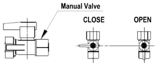
- Wait five (5) minutes to clear out any gas. Then smell for gas, including near the floor. If you smell gas, STOP! Follow "B" in the safety information above. If you don't smell gas, go to the next step.
- Turn the manual gas valve counterclockwise to the full ON position.
- Turn on all electric power to the appliance using the ON/OFF button.
- Set the thermostat to desired setting.
- Open a hot water tap. If the appliance will not operate, follow the instructions "To Turn Off Gas To Appliance" and call your licensed professional or gas supplier. See manual for additional information.
TO TURN OFF GAS TO APPLIANCE
- Turn off all electric power to the appliance using the ON/OFF button.
-
Set the thermostat to lowest setting.
-
Locate the manual gas valve on the side of the heater. Turn the manual valve clockwise to the full OFF position.
52 KCM Series Manual

WARNING
- Before operating, smell all around the appliance area for gas. Be sure to smell next to the floor because some gas is heavier than air and will settle on the floor.
- Keep the area around the appliance clear and free from combustible materials, gasoline, and other flammable vapors and liquids.
Always check the water temperature before entering a shower or bath. - Do not use this appliance if any part has been under water. Immediately call a licensed professional to inspect the appliance and to replace any part of the control system and any gas control which has been under water.
- Should overheating occur or the gas supply fail to shut off, turn off the manual gas control valve to the appliance.
-
Do not adjust the DIP switch unless specifically instructed to do so.
-
Do not use an extension cord or an adapter plug with this appliance.
- Any alteration to the appliance or its controls can be dangerous and will void the warranty.
- If you install this water heater in an area that is known to have hard water or that causes scale build-up the water must be treated and/or the heat exchanger flushed regularly. Rinnai provides a "Scale Control System" as an accessory that offers superior lime scale prevention and corrosion control by feeding a blend of control compounds into the water supply. Damage and repair due to corrosive compounds in the air is not covered by warranty.
- Keep the air intake location free of chemicals, such as chlorine or bleach, that produce fumes. These fumes can damage components and reduce the life of your appliance. Damage and repair due to scale in the heat exchanger is not covered by warranty.
How to Set the Temperature
A maintenance display or status monitor is provided in the front panel to indicate operating status and error codes. This water heater requires a minimum flow rate to operate. This rate can be found on the specification page in this manual. In some cases when you are not getting hot water or if the water alternates between hot and cold, it is due to the water flow being below or close to the minimum flow rate. Increasing the flow rate should resolve these problems in these cases.
If you are experiencing issues with higher temperature settings, then reduce the temperature setting. Selecting a temperature closer to that which is actually used at the faucet will increase the amount of hot water being delivered to the faucet, due to less cold water mixing at the fixture.

DANGER
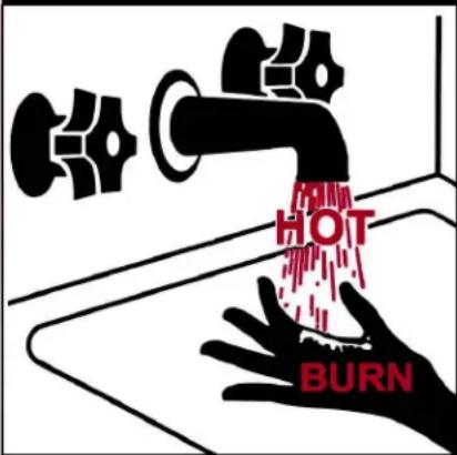
Water temperatures over 125ircF (52ircC) can cause severe burns or scalding resulting in death.
Hot water can cause first degree burns with exposure for as little as:
3 seconds at 140irc F (60ircC)
20 seconds at 130irc F (54ircC)
8 minutes at 120irc F (49ircC)
Children, disabled, or elderly are at highest risk of being scalded.
Feel water before bathing or showering.
Temperature Options Without a Temperature Controller
The default temperature setting for this appliance installed without a temperature controller is 120ircF (49ircC) . If desired, the temperature setting can be changed by adjustment of the dip switches:
| DIPSW1 | ||
| SW5 SW6 | ||
| 120° F OFF OFF | ||
| 125° F ON OFF | ||
| 135° F OFF ON | ||
| 140° F ON ON | ||
Without a controller the status monitor (see page 56) will show the temperature as follows:
| Fahrenheit °F | 120 | 125 | 135 | 140 |
| Celsius °C | 49 | 52 | 57 | 60 |
| Displayed As | 1 | 2 | 3 | 4 |
How to use the Optional Temperature Controller
The units referenced in this manual do not include a temperature controller.
The MC-91-2 controller is the standard temperature controller.
DO NOT repeatedly operate the water heater and then use a hot water tap while the controller is turned off.
Operating the water heater in this way to alternately produce hot water may cause water to condense on the outside of internal parts and accumulate in the water heater cabinet.

Dimensions (inches): 3.5W× 4.75H× 0.75D

- If the water heater is off, press the Power button to turn on.
- If the Priority light is off, then press the "Priority button" on the temperature controller. The orange Priority light will glow indicating that this controller is controlling the temperature and that the water heater is ready to supply hot water. (The priority can only be changed while no hot water is running.)
- Press the up or down buttons to obtain the desired temperature setting.
| NOTICE | Check local codes for the maximum water temperature setting allowed when used in nursing homes, schools, day care centers, and all other public applications. |
| NOTICE | If a newly installed unit with a controller has not been powered for at least 6 hours then the temperature will return to the default setting of 120° F (49°C) if power is interrupted. |
| NOTICE | There may be a variation between the temperature displayed on the temperature controller and the temperature at the tap due to weather conditions or the length of pipe to the water heater. |

All hot water sources are able to provide water at this temperature setting until it is changed again at this or another temperature controller.
Temperatures Available with a Controller
The water heater can deliver water at only one temperature setting at a time. The available temperatures are provided below. A temperature lower than 120ircF ( 49ircC ) can be obtained at the tap by mixing with cold water.
To change the temperature scale from Celsius to Fahrenheit or vice versa, press and hold the "On/Off" button for 5 seconds while the water heater is OFF.
| Temperature Settings Available | |||||
| Fahrenheit °F | 120 | 125 | 130 | 135 | 140 |
| Celsius °C | 49 | 52 | 54 | 57 | 60 |
Setting Controller to Mute
On the MC-91-2 to eliminate the beeps when keys are pressed or to turn the beeps back on, press and hold both the up and down buttons until a beep is heard (approximately 5 seconds).
Locking the Controller
The MC-91-2 controller can be locked by pressing the Priority button and the up button together for 5 seconds. A beep will sound confirming that the controller is locked. The display will alternately show "LOC", the temperature setting, and a diagnostic code if one has been activated. All of the controllers in the system are also locked.
To unlock the controller press the Priority button and the up button together for 5 seconds.
Diagnostic Codes
This water heater is designed to display diagnostic codes. If there is a potential operation concern refer to the code and remedy on the next page.
Diagnostic Information (on status monitor)
-- Initial (When unit is connected to power).
(non-displayed) Standby (power is supplied but there is no demand for hot water).
1,2,3 or 4 Hot water is being supplied without controller.
ON Hot water is being supplied with controller
FL or FH Stands for Forced Low and Forced High combustion. Only seen during the gas pressure setting procedure which is done when certain components are replaced.
Error code flashing The error code will stop flashing after the problem is corrected and the water heater supplies hot water.

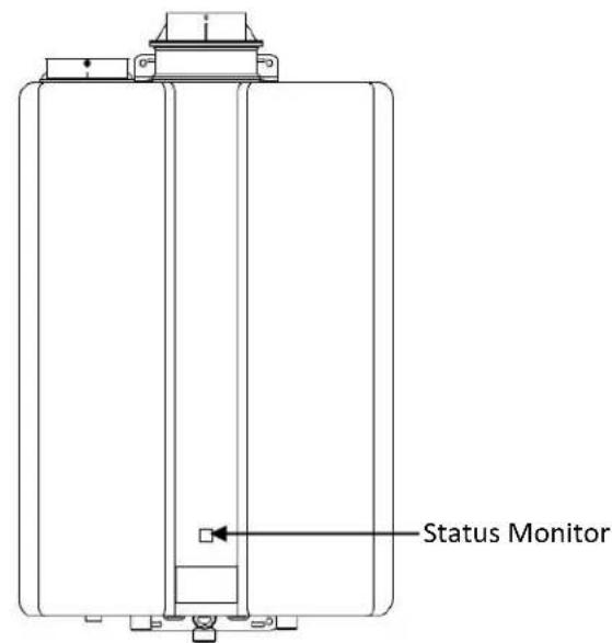
To Display Diagnostic Information (with controller)
To display the most recent diagnostic information code press and hold the "On/Off" button for 2 seconds on the MC-91-2 controller. While holding the "On/Off" button press the up button. The last 9 diagnostic codes will flash one after the other. To exit this mode press the "On/Off" and up button as before.
To enter or exit the maintenance monitor information mode, press and hold the down button for 2 seconds and without releasing it press the ON/OFF button.
To obtain the water flow rate: press the up or down buttons until "01" displays. The water flow rate will then appear. For example "58" means 5.8 gal/min.
To obtain the outgoing water temperature press the up or down buttons until "02" displays. The temperature will appear in degrees Fahrenheit.
| Data Unit No. | ||
| 01 | Water flow rate | 0.1 gal/min |
| 02 | Outgoing water temperature | Degrees Fahrenheit |
| Some of the checks below should be done by a licensed professional. Consumers should never attempt any action that they are not qualified to perform. | ||
| Code Definition Remedy | ||
| 10 Air Supply or Exhaust Blockage | Check that nothing is blocking the flue inlet or exhaust. Check all vent components for proper connections. | |
| licensed professional only | Ensure approved venting materials are being used. Ensure vent length is within limits. Verify DIP switches are set properly. Check fan for blockage. | |
| 11 No Ignition (heater not turning on) | Check that the gas is turned on at the water heater, gas meter, or cylinder. If the system is propane, make sure that gas is in the tank. Ensure appliance is properly grounded. | |
| licensed professional only | Ensure gas type and pressure is correct. Ensure gas line, meter, and/or regulator is sized properly. Bleed all air from gas lines. Verify DIP switches are set properly. Ensure igniter is operational. Check igniter wiring harness for damage. Check gas solenoid valves for open or short circuits. Remove burner cover and ensure all burners are properly seated. Remove burner plate and inspect burner surface for condensation or debris. Check the ground wire for the PC board. | |
| 12 No Flame | Check that the gas is turned on at the water heater, gas meter, or cylinder. Check for obstructions in the flue outlet. If the system is propane, make sure that gas is in the tank. | |
| licensed professional only | Ensure gas line, meter, and/or regulator is sized properly. Ensure gas type and pressure is correct. Bleed all air from gas lines. Ensure proper venting material was installed. Ensure condensation collar was installed properly. Ensure vent length is within limits. Verify DIP switches are set properly. Check power supply for loose connections. Check power supply for proper voltage and voltage drops. Ensure flame rod wire is connected. Check flame rod for carbon build-up. Disconnect and reconnect all wiring harnesses on unit and PC board. Check for DC shorts at components. Check gas solenoid valves for open or short circuits. Remove burner plate and inspect burner surface for condensation or debris. | |
| 14 Thermal Fuse has activated | Check for restrictions in air flow around unit and vent terminal. | |
| licensed professional only | Ensure SW5 in DIPSW 2 is in the off position. Check gas type of unit and ensure it matches gas type being used. Check for low water flow in a circulating system causing short-cycling. Ensure dip switches are set to the proper position. Check for foreign materials in combustion chamber and/or exhaust piping. Check heat exchanger for cracks and/or separations. Check heat exchanger surface for hot spots which indicate blockage due to scale build-up. Refer to instructions in manual for flushing heat exchanger. Hard water must be treated to prevent scale build up or damage to the heat exchanger. Measure resistance of safety circuit. Ensure high fire and low fire manifold pressure is correct. Check for improper conversion of product. | |
| 16 Over Temperature Warning (safety shutdown because unit is too hot) | Check for restrictions in air flow around unit and vent terminal. | |
| licensed professional only | Check for low water flow in a circulating system causing short-cycling. Check for foreign materials in combustion chamber and/or exhaust piping. Check for blockage in the heat exchanger. | |
| Code | Definition | ||
| 19 | Electrical Grounding | licensed professional only | Check all components for electrical short. |
| 25 | Condensate Trap is full | Check condensate trap and drain line for blockage. | |
| licensed professional only | Replace condensate trap. | ||
| 32 | Outgoing Water Temperature Sensor | Check sensor wiring for damage.Measure resistance of sensor.Clean sensor of scale build-up.Replace sensor. | |
| 33 | Heat Exchanger Outgoing Temperature Sensor | ||
| 38 | Exhaust Gas Temperature Sensor | ||
| 41 | Outside Temperature Sensor | ||
| 52 | Modulating Solenoid Valve Signal | Check modulating gas solenoid valve wiring harness for loose or damaged terminals.Measure resistance of valve coil. | |
| 54 | High Exhaust Gas Temperature | Check heat exchanger surface for hot spots which indicate blockage due to scale build-up. Refer to heat exchanger flushing instructions within this manual. Hard water must be treated to prevent scale build up or damage to the heat exchanger.Contact a licensed professional. | |
| 61 | Combustion Fan | Ensure fan will turn freely.Check wiring harness to motor for damaged and/or loose connections.Measure resistance of motor winding. | |
| 65 | Water Flow Control | The water flow control valve has failed to close during the bath fill function. Immediately turn off the water and discontinue the bath fill function. Contact a licensed professional to service the appliance. | |
| 70 | PC Board | Check PC board DIP switches for correct positionCHECK the connection harness at the connection on the PC board REPLACE PC board. | |
| 71 | Solenoid Valve Circuit | Replace the PC Board. | |
| 72 | Flame Sensing Device | Replace the PC Board. | |
| LC # (LC0, LC1, LC2,...) | Scale Build-up in Heat Exchanger (when checking maintenance code history, "00" is substituted for "LC") | LC (only when a controller is installed , the monitor shows LC0~LC9) indicates that there is scale build up in the heat exchanger and that the heat exchanger needs to be flushed to prevent damage. Refer to the flushing instructions in the manual. Hard water must be treated to prevent scale build up or damage to the heat exchanger.To operate the water heater temporarily until the heat exchanger can be flushed, push the On/Off button (when a controller is installed) on the temperature controller 5 times. Repeated LC codes will eventually lockout the water heater.Please call Rinnai technical department. | |
| FF | Maintenance has been performed(with controller only) | Indicates a licensed professional performed maintenance or corrected an issue. | |
| No code | Nothing happens when water flow is activated. | Clean inlet water supply filter.On new installations ensure hot and cold water lines are not reversed.Verify you have at least the minimum flow rate required to fire unit. | |
| licensed professional only | Check for cold to hot cross over. Isolate circulating system if present. Turn off cold water to the unit, open pressure relief valve; if water continues to flow, there is bleed over in your plumbing.Verify turbine spins freely.Measure the resistance of the water flow control sensor.If the display is blank and clicking is coming from the unit, disconnect the water flow servo motor (GY, BR, O, W, P, BL, R). If the display comes on replace the water flow servo motor. |
Required Maintenance
The appliance must be inspected annually by a licensed professional. Repairs and maintenance shall be performed by a licensed professional. The licensed professional must verify proper operation after servicing.

WARNING
To protect yourself from harm, before performing maintenance:
- Turn off the electrical power supply by unplugging the power cord or by turning off the electricity at the circuit breaker. (The temperature controller does not control the electrical power.)
- Turn off the gas at the manual gas valve, usually located immediately below the water heater.
- Turn off the incoming water supply. This can be done at the isolation valve immediately below the water heater or by turning off the water supply to the building.

WARNING
Keep the appliance area clear and free from combustible materials, gasoline, and other flammable vapors and liquids.
The following maintenance items are required for the proper operation of your water heater.
The appliance must be inspected annually by a licensed professional. Repairs and maintenance shall be performed by a licensed professional. The licensed professional must verify proper operation after servicing.
Cleaning
It is imperative that control compartments, burners, and circulating air passageways of the appliance be kept clean.
Clean as follows:
- Turn off and disconnect electrical power. Allow to cool.
- Close the water shut off valves. Remove and clean the water inlet filter.
- Remove the front panel by removing 4 screws.
- Use pressurized air to remove dust from the main burner, heat exchanger, and fan blades. Do not use a wet cloth or spray cleaners on the burner. Do not use volatile substances such as benzene and thinners. They may ignite or fade the paint.
- Use soft dry cloth to wipe cabinet.
Vent System
The vent system should be inspected at least annually for blockages or damage. If the vent is blocked contact a licensed professional.
Motors
Motors are permanently lubricated and do not need periodic lubrication. However you must keep the fan and motor free of dust and dirt by cleaning annually.
Temperature Controller
Use a soft damp cloth to clean the temperature controller. Do not use solvents.
Lime / Scale Build-up
If you receive diagnostic code "LC#" (LC1, LC2,...), refer to the procedure, Flushing the Heat Exchanger. Refer to the section on Water Quality to see if your water needs to be treated or conditioned. (When checking maintenance code history with temperature controller, "00" is substituted for "LC#".)
The water must be potable, free of corrosive chemicals, sand, dirt, or other contaminants. It is up to the installer to ensure the water does not contain corrosive chemicals, or elements that can affect or damage the heat exchanger. Water that contains chemicals exceeding the levels below affect and damage the heat exchanger. Replacement of the heat exchanger due to water quality damage is not covered by the warranty.
Snow Accumulation
Keep the area around flue terminal free of snow and ice. The appliance will not function properly if the intake air or exhaust is impeded (blocked or partially blocked) by obstructions.
Coastal Installations
Installations located in or near coastal areas may require additional maintenance due to corrosive airborne ocean salt.
Clean the water filter
Clean the inlet water filter by closing the cold and hot water inlet isolation (shut-off) valves. Put a bucket
under the filter at the bottom of the water heater to catch any water that is contained inside the unit. Unscrew the water filter. Rinse the filter to remove any debris. Install the filter and open the isolation valves.

WARNING
Testing the pressure relief valve should only be performed by a licensed professional. Water discharged from the pressure relief valve could cause severe burns instantly or death from scalds.
Pressure Relief Valve (PRV):
Operate the PRV manually once a year. In doing so, it will be necessary to take precautions with regard to the discharge of potentially scalding hot water under pressure. Ensure discharge has a safe place to flow. Contact with your body or other property may cause damage or harm.
Visual Inspection of Flame
Verify proper operation after servicing. The burner must flame evenly over the entire surface when operating correctly. The flame must burn with a clear, blue, stable flame. See the parts breakdown of the burner for the location of the view ports.
The flame pattern should be as shown in the figures below:
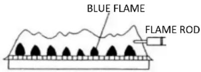
SATISFACTORY
FRONTVIEW
UNSATISFACTORY

FRONTVIEW
Freeze Protection
Make sure in case of freezing weather that the water heater and its water lines are adequately protected to prevent freezing. Damage due to freezing is not
covered by the warranty. Refer to the section on Freeze Protection. The unit may be drained manually. However, it is highly recommended that:
- drain down solenoid valves be purchased and installed that will automatically drain the unit if power is lost. These are available in a kit, 104000059. (The condensate trap drain plug and water drain plug are not affected by the auto drain down solenoid valves and will have to be manually opened.)
- a surge protector with terminals be purchased and installed which allows the solenoid valves to operate if the unit is disabled due to a diagnostic code. This is available as 104000057.
Winterization
These recommendations are intended to suggest practices that are effective for winterizing the water heater. They should be used as a guide only. No liability is assumed for any issues resulting from the use of this information.
GAS
Shut off the gas to the water heater. It is generally preferable to shut off the gas service to the entire location if gas is not going to be used.
WATER
Shut off the cold water supply to the water heater. It is generally preferable to shut off the water to the entire location if water is not going to be used.
Drain the water heater by opening the drain valves on the cold water line and hot water line.
Open several hot water taps and remove the filter assembly at the water inlet in order to allow room for expansion in case there is water in the lines that freeze.
ELECTRIC
Disconnect the power supply by either unplugging the electrical cord or by turning off the circuit breaker to the water heater to prevent potential damage from irregular power surges or interruptions.
VENT TERMINATION
Place a cover over the vent termination (intake and exhaust) if it can be safely accessed. The cover should be easy to apply and remove. This will prevent debris, leaves, and small animals from entering the venting and water heater which could cause air flow
Flushing the Heat Exchanger
An LC0~LC9 or "00" or 58 diagnostic code indicates the unit is beginning to lime up and must be flushed. Failure to flush the appliance will cause damage to the heat exchanger. Damage caused by lime build-up is not covered by the unit's warranty. Rinnai strongly recommends installation of isolation valves to allow for flushing of the heat exchanger.
- Disconnect electrical power to the water heater.
- Close the shutoff valves on both the hot water and cold water lines (V3 and V4).
- Connect pump outlet hose (H1) to the cold water line at service valve (V2).
- Connect drain hose (H3) to service valve (V1).
- Pour 4 gallons of undiluted virgin, food grade, white vinegar into pail.
- Place the drain hose (H3) and the hose (H2) to the pump inlet into the cleaning solution.
- Open both service valves (V1 and V2) on the hot water and cold water lines.
- Operate the pump and allow the vinegar to circulate through the water heater for at least 1 hour at a rate of 4 gallons per minute (15.1 liters per minute).
- Turn off the pump.
- Rinse the vinegar from the water heater as follows:
a. Remove the free end of the drain hose (H3) from the pail. Place in sink or outside to drain.
b. Close service valve, (V2), and open shutoff valve, (V4). Do not open shutoff valve, (V3).
c. Allow water to flow through the water heater for 5 minutes.
d. Close shutoff valve (V4). When unit has finished draining remove the in-line filter at the cold water inlet and clean out any residue. Place filter back into unit and open valve (V4).
e. Close service valve, (V1), and open shutoff valve, (V3).
- Disconnect all hoses
- Restore electrical power to the water heater.
Following flush procedure call technical assistance (1-800-621-9419) for PCB reset information.
KEY
3/4" Ball Valve
3/4" Union
Check Valve
Pressure Relief Valve
Pressure Regulator
Circulating Pump
Boiler Drain Valve
Solenoid Valve
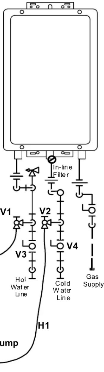
Manual Draining of the Water Heater

WARNING
To avoid burns, wait until the equipment cools down before draining the water. The water in the appliance will remain hot after it is turned off.
If the water heater is not going to be used during a period of possible freezing weather, it is recommended that the water inside the water heater be drained.
To manually drain the water:
- Shut off cold water supply and gas supply.
- Turn off the temperature controller (if it is installed).
- Disconnect the power to the water heater.
- Place a container to catch the water. Open hot water tap or open hot water drain plug at the hot water outlet.
- Remove water filter to drain the cold water.
- Unscrew the water drain plug from the condensate drain line next to the hot water outlet.
- Remove the condensate trap drain plug and allow to drain.
To resume normal operation:
- Confirm that all water drain plugs are removed, that the gas supply is turned off, and that all taps are closed.
- Insert the condensate trap drain plug.
- Screw in the water drain plugs. (Avoid over tightening)
- Screw in the water filter in the cold water inlet.
- Open the cold water supply.
- Open a tap and confirm that water flows, and then close.
- Turn on the power.
- After confirming that the temperature controller is off (if it is installed), turn on the gas supply.
- Turn on the temperature controller (if it is installed).

Running a low volume of water through the water heater to prevent freezing
If the temperature exceeds the ability of the water heater to freeze protect itself, or if power is lost, the following steps may prevent the water heater and external piping from freezing. (Units connected with EZ Connect (2 unit link) should be drained to prevent freezing if not in use.)
- Turn the water heater off.
- Close the gas supply valve.
- Turn on a hot water tap to flow water about 0.1 gal/min or where the stream is about 0.2 inches thick.

0.1 gal/min or about 0.2 inch thick
When the water heater or external piping has frozen
- Do not operate the water heater if it or the external piping is frozen.
- Close the gas and water valves and turn off the power.
- Wait until the water thaws. Check by opening the water supply valve.
- Check the water heater and the piping for leaks.
62 KCM Series Manual
State Regulations
NOTICE BEFORE INSTALLATION
This direct-vent appliance must be installed by a licensed professional. If you are not properly trained, you must not install this unit.
IMPORTANT: In the State of Massachusetts (248 CMR 4.00 & 5.00)
For all side wall horizontally vented gas fueled equipment installed in every dwelling, building or structure used in whole or in part for residential purposes, including those owned or operated by the Commonwealth and where the side wall exhaust vent termination is less than seven (7) feet above finished grade in the area of the venting, including but not limited to decks and porches, the following requirements shall be satisfied:
- INSTALLATION OF CARBON MONOXIDE DETECTORS. At the time of installation of the side wall horizontal vented gas fueled equipment, the installing plumber or gasfitter shall observe that a hard wired carbon monoxide detector with an alarm and battery back-up is installed on the floor level where the gas equipment is to be installed. In addition, the installing plumber or gasfitter shall observe that a battery operated or hard wired carbon monoxide detector with an alarm is installed on each additional level of the dwelling, building or structure served by the side wall horizontal vented gas fueled equipment. It shall be the responsibility of the property owner to secure the services of qualified licensed professionals for the installation of hard wired carbon monoxide detectors
a. In the event that the side wall horizontally vented gas fueled equipment is installed in a crawl space or an attic, the hard wired carbon monoxide detector with alarm and battery back-up may be installed on the next adjacent floor level.
b. In the event that the requirements of this subdivision can not be met at the time of completion of installation, the owner shall have a period of thirty (30) days to comply with the above requirements; provided, however, that during said thirty (30) day period, a battery operated carbon monoxide detector with an alarm shall be installed.
- APPROVED CARBON MONOXIDE DETECTORS. Each carbon monoxide detector as required in accordance with the above provisions shall comply with NFPA 720 and be ANSI/UL 2034 listed and IAS certified.
- SIGNAGE. A metal or plastic identification plate shall be permanently mounted to the exterior of the building at a minimum height of eight (8) feet above grade directly in line with the exhaust vent terminal for the horizontally vented gas fueled heating appliance or equipment. The sign shall read, in print size no less than one-half (1/2) inch in size, "GAS VENT DIRECTLY BELOW, KEEP CLEAR OF ALL OBSTRUCTIONS".
- INSPECTION. The state or local gas inspector of the side wall horizontally vented gas fueled equipment shall not approve the installation unless, upon inspection, the inspector observes carbon monoxide detectors and signage installed in accordance with the provisions of 248 CMR 5.08(2)(a)1 through 4.
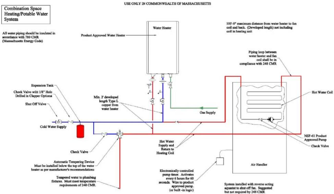
KCM Series Manual 63
Replacement Parts
The Technical Sheet that is located inside the front cover of the water heater contains a complete illustrated parts list.
(Images are for illustration purposes only, actual parts may be differ in appearance.)
| Tech Sheet Item No. | |
| Gas Control Assembly 100 | |
| Electrode / Flame Rod Kit 116 | 117 |
| Fan Assembly / Motor 125 | |
| Primary Heat Exchanger Assy | 143 |
| Secondary Heat Exchanger- Indoor | 160 |
| Secondary Heat Exchanger- Outdoor | 161 |
| Water Flow Servo & Sensor 401 | |
| Water Filter Assy 412 | |
| PC Board 700 | |
| Anti Frost Unit 701 | |
| Ignitor 706 | |
| Thermal Fuse Harness 723 |
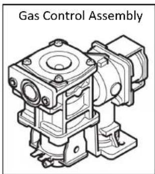

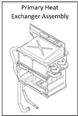


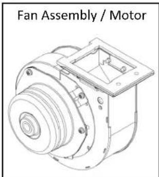


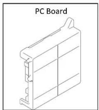
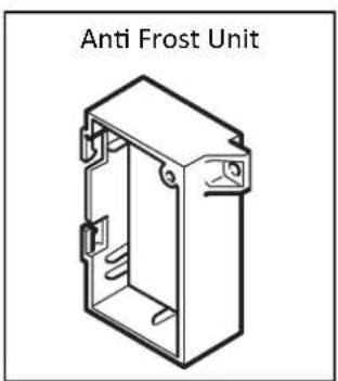


Limited Warranty for RUCS65i, RUS65e, RUCS75i, & RUS75e Value Series Water Heater
What is covered?
The Rinnai Standard Limited Warranty covers any defects in materials or workmanship when the product is installed and operated according to Rinnai written installation instructions, subject to the terms within this Limited Warranty document. This Limited Warranty applies only to products that are installed correctly in the United States and Canada. Improper installation may void this Limited Warranty. In order for this warranty to apply, it is required that you use a licensed professional who has attended a Rinnai installation training class before installing this water heater. This warranty coverage applies to residential installations only, not for commercial applications, (any installation other than a single family dwelling). This Limited Warranty coverage as set out in the table below extends to the original purchaser and subsequent owners, but only while the product remains at the site of the original installation. This Limited Warranty only extends to the first / original installation of the product and terminates if the product is moved or reinstalled at a new location.
How long does coverage last?
| Item | Period of Coverage (from date of purchase) | |
| Residential | If used for both residential water heating and space heating purposes | |
| Heat Exchanger | 12 years [1][2] | 10 years [1] |
| All Other Parts and Components | 5 years [1] | 5 years [1] |
| Reasonable Labor | 1 year | 1 year |
[1] Period of coverage is reduced to 3 years from date of purchase when used as a recirculating water heater within a hot water recirculation loop, where the water heater is in series with a recirculation system and all recirculating water flows through the water heater, and where an aquastat / thermostat, timer, or an on-demand recirculation system is not incorporated.
[2] The Rinnai Limited Warranty for a heat exchanger used in a recirculation system which is controlled through an aquastat / thermostat, or timer, or an on-demand system is 1.2 years for residential applications.
What will Rinnai do?
Rinnai will repair or replace the covered product or any part or component that is defective in materials or
Rinnai®
IMPORTANT CONSIDERATIONS POUR L'EMPLACEMENT (Suite) :
| DIPSW1 | ||
| SW5 SW6 | ||
| 120° F OFF OFF | ||
| 125° F ON OFF | ||
| 135° F OFF ON | ||
| 140° F ON ON | ||
Raccord-union 3 / 4
Clapet anti-retour
Soupape de décharge

www.rinnai.us/warranty
A tradition of
TRUE RELIABILITY.
For nearly 100 years, we at Rinnai have been fiercely committed to delivering nothing less than a superior experience at every touch point.
Beyond manufacturing the highest quality products, our people stand behind all that we make—before, during and long after installation. From the 24/7/365 technical support for professionals, to our national network of independent installers for homeowners, to on-staff engineers who can assist with choosing the right products and sizes—we're inspiring confidence right along with the comfort our solutions provide.

Learn more about Rinnai high-performance Tankless Water Heaters, Hybrid Tank-Tankless Water Heaters, Boilers, Vent-Free Fan Convectors and EnergySaver® Direct Vent Wall Furnaces at www.rinnai.us
Rinnai.
Rinnai America Corporation dot 103 International Drive, Peachtree City, GA 30269
Toll-Free: 1-800-621-9419 • Phone: 678-829-1700 • www.rinnai.us
2015 Rinnai America Corporation. Rinnai is continually updating and improving products; therefore, specifications are subject to change without prior notice. Local, state, provincial, federal and national fuel gas codes must be adhered to prior to and upon installation.
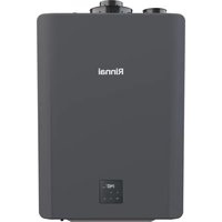

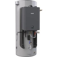


- Direct Vent Tankless Water Heater Installation and Operation Manual
- ANSI Z21.10.3 dot CSA 4.3
- READ ALL OF THE INSTRUCTIONS THOROUGHLY BEFORE INSTALLING OR OPERATING THIS WATER HEATER.
- WARNING
- Table of Contents
- Important Safety Information
- Safety Definitions
- Safety Behaviors and Practices for the Consumer and Installer
- CAUTION
- California Proposition 65:
- Installation Instructions (for the licensed professional)
- Type of installation
- Installation Steps
- General Instructions Installer Qualifications
- DO NOT
- MUST DO
- General Instructions (continued)
- INFORMATION
- Prepare for installation
- Parts included
- Tools needed
- Tools that might be needed
- Materials needed
- Materials that may be needed
- Determine Installation Location
- Water Quality
- Environment
- IMPORTANT CONSIDERATIONS FOR:
- Direct Vent Terminal Clearances (Indoor Units)
- KCM Series Manual
- Additional clearances
- RUCS65i, RUCS75i
- RUS65e, RUS75e
- Freeze Protection
- Checklist to Determine Installation Location
- NOTICE
- Remove the Front Panel
- Installation of Venting (indoor models only)
- Venting Guidelines
- Determining Vent Configuration
- Determining Vent Configuration (continued)
- Removal of Intake Cap
- Maximum vent length
- Maximum Vent Length with Concentric Venting
- Maximum Vent Length for Centrotherm 2 Pipe
- Vent length using short radius elbow
- Vent length using long radius elbow
- Maximum Vent Length with Twin Pipe PVC / CPVC
- Vertical Termination
- Flue Installation with Centrotherm Venting (indoor models only)
- DANGER
- Twin Pipe PVC/CPVC Vent Installation Requirements:
- IMPORTANT CONSIDERATIONS FOR LOCATION:
- IMPORTANT CONSIDERATIONS FOR LOCATION (continued):
- Exhaust and Combustion Air Intake Pipe Diameters and Maximum Lengths:
- Determining Total System Equivalent Length
- OPTION 1:
- Calculation of equivalent piping lengths for venting system:
- Calculation:
- ATTENTION
- OPTION 2:
- Adapter Installation Configurations:
- Required Parts For 3" PVC/CPVC Assembly Configuration
- Required Parts For 4" PVC/CPVC Assembly Configuration
- Certified PVC/CPVC Vent Termination Options
- Vent Termination Configurations
- Termination Installation
- IPEX Concentric Vent Kit (CVK) Installation
- Certified PVC/CPVC Vent Termination Options (continued)
- IPEX Concentric Vent Kit Assembly (System 636):
- MECHANICALLY FASTENED RAIN CAP:
- NOTE
- VENTING INSTALLATION SEQUENCE
- 3" and 4" Low Profile Vent Termination Kits
- Installation:
- Twin Pipe (PVC/CPVC) Terminations
- PVC/CPVC Sidewall (Tee and Snorkel) Terminations:
- PVC/CPVC Roof (Tee and upside down "U") Terminations:
- Multiple Water Heater Installation - Through the Roof
- Vertical Termination of U-Vent and Combustion Air Pipe on a Pitched Roof
- Basic Instructions for Cementing Joints:
- Parts Information
- Parts Information (continued)
- Vent Components and Assigned Equivalent Lengths:
- PVC/CPVC Equivalent Vent Length Calculation Sheet
- Condensate
- Checklist for Venting and Condensate (indoor models only)
- Installation of Plumbing
- Pressure Relief Valve Requirements
- Isolation Valves
- Piping Requirements
- Isolation Valves and Pressure Relief Valve (PRV)
- Isolation Valves Installation Instructions:
- Pressure Relief Valve Installation Instructions:
- Pressure Relief Valve Maintenance:
- Piping Diagram for Basic Installation
- Connect Water Heater to Water Supply
- Checklist for Plumbing
- Installation of Gas Supply
- General Instructions
- Size the gas pipe
- Example:
- Pipe Sizing Table - Natural Gas
- Pipe Sizing Table - Propane Gas
- Connect Electricity
- Adjustment for High Altitude Installations
- Adjustment for Vent Length (indoor models only)
- Checklist for Gas and Electricity
- Installation of Optional Temperature Controller
- Controller Location
- Cable Lengths and Sizes
- Configurations
- Mounting the controller
- Final Checklist
- Technical Data
- Specifications
- Dimensions
- Ladder Diagram
- Rinnai
- Direct Vent Tankless Water Heater Operation Instructions
- Important Facts about your Water Heater
- Consumer Operation Guidelines for the Safe Operation of your Water Heater
- OPERATING INSTRUCTIONS
- TO TURN OFF GAS TO APPLIANCE
- How to Set the Temperature
- Temperature Options Without a Temperature Controller
- How to use the Optional Temperature Controller
- Temperatures Available with a Controller
- Setting Controller to Mute
- Locking the Controller
- Diagnostic Codes
- Diagnostic Information (on status monitor)
- To Display Diagnostic Information (with controller)
- Required Maintenance
- Cleaning
- Vent System
- Motors
- Temperature Controller
- Lime / Scale Build-up
- Snow Accumulation
- Coastal Installations
- Clean the water filter
- Pressure Relief Valve (PRV):
- Visual Inspection of Flame
- Winterization
- GAS
- WATER
- ELECTRIC
- VENT TERMINATION
- Flushing the Heat Exchanger
- KEY
- Manual Draining of the Water Heater
- To manually drain the water:
- To resume normal operation:
- Running a low volume of water through the water heater to prevent freezing
- When the water heater or external piping has frozen
- State Regulations
- IMPORTANT: In the State of Massachusetts (248 CMR 4.00 & 5.00)
- Replacement Parts
- Limited Warranty for RUCS65i, RUS65e, RUCS75i, & RUS75e Value Series Water Heater
- What is covered?
- What will Rinnai do?
- Rinnai®
- IMPORTANT CONSIDERATIONS POUR L'EMPLACEMENT (Suite) :
- A tradition of
- Rinnai.
Brand : Rinnai
Model : RUCS65iP
Category : Boiler