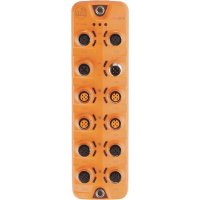
AL1202 - Server IFM - Free user manual and instructions
Find the device manual for free AL1202 IFM in PDF.


User questions about AL1202 IFM
0 question about this device. Answer the ones you know or ask your own.
Ask a new question about this device
Download the instructions for your Server in PDF format for free! Find your manual AL1202 - IFM and take your electronic device back in hand. On this page are published all the documents necessary for the use of your device. AL1202 by IFM.
USER MANUAL AL1202 IFM
Operating instructions (supplement)
System description
Deactivation of UA without interaction in IO-Link
systems with suitable devices
Contents
1 Preliminary note.... 3
1.1 Purpose of the document 3
1.2 Symbols used.... 3
1.3 Warnings.... 3
1.4 Change history.... 3
2 Safety instructions 5
2.1 Required background knowledge 5
3 Intended use 6
4 System description.... 7
4.1 Isolation 7
4.2 Actuators 8
4.3 Supported devices (ALxxxx) 8
4.4 Safety relay 9
4.5 Star point connections.... 10
4.6 Voltage supply.... 10
5 Certification.... 11
1 Preliminary note
1.1 Purpose of the document
This document describes a concept for a system for deactivating the supply voltage of an actuator without interaction using a safety relay and suitable devices of the ifm device families AL1xxx (IO-Link master) and AL2xxx (IO-Link input / output module).
1.2 Symbols used
√ Requirement
Instruction
Reaction, result
bold Designation of keys, buttons or indications
→ Cross-reference without link
→ Cross-reference with link
Important note Non-compliance may result in malfunction or interference
Information Supplementary note
1.3 Warnings
Warnings indicate the possibility of personal injury and damage to property. This enables safe product handling. Warnings are graded as follows:

WARNING
Warning of serious personal injury
▷ If the warning is not observed, fatal and serious injuries are possible.

CAUTION
Warning of minor to moderate personal injury
▷ If the warning is not observed, minor to moderate injuries are possible.

ATTENTION
Warning of damage to property
▷ If the warning is not observed, damage to property is possible.
1.4 Change history
| Issue | Subject | Date |
| 00 | New creation of the document | 04 / 2024 |
| 01 | Added: supported devices AL2236, AL4302, AL4303, AL4322, AL4323 | 07 / 2024 |
| 02 | Added: supported devices AL4342, AL4343 | 01 / 2025 |
| 03 | Added: supported devices AL2507, AL2527, AL2607, AL2627 Added: note on discharging the capacitors, Actuators 8 | 01 / 2025 |
| 04 | Added: supported devices AL2537, AL2637 Supplemented supported hardware version AA for devices AL2236, AL2336, AL2607, AL2507, AL2527, AL2537 Removed: supported devices AL2230, AL2330, AL2231, AL2331 Added: Internal device measures to achieve PL d, Supported devices (ALxxxx) 9 | 01 / 2026 |
2 Safety instructions
- The system architect is responsible for the safety of the system.
- The system architect undertakes to perform a risk assessment and to create documentation in accordance with legal and normative requirements to be provided to the operator and user of the system. This documentation must contain all necessary information and safety instructions for the operator, the user and, if applicable, for any service personnel authorised by the architect of the system.
- Read this document before setting up the system and keep it during the entire service life.
- Only use the system for its intended purpose (→ Intended use).
- If the operating instructions or the technical data are not adhered to, personal injury and/or damage to property may occur.
- Installation, electrical connection, set-up, programming, configuration, operation and maintenance of the system must be carried out by personnel qualified and authorised for the respective activity.
- Protect units and cables against damage.
- Observe other applicable documents, System description ➞ 7.
2.1 Required background knowledge
The information described in this document is intended only for
- qualified personnel who plan and develop safety equipment for machines and systems and are familiar with safety regulations in the workplace and accident prevention measures.
- qualified personnel who are familiar with the implementation of functional safety functions and standards.
Qualified personnel are people who, because of their education, experience, and training, and their knowledge of relevant standards, regulations, accident prevention, and operating conditions, have been authorised by those responsible for the safety of the plant to carry out any required operations and who are able to recognise and avoid any possible dangers.
3 Intended use
Intended use:
The following applies to the supported devices: The UA supply voltage of an actuator can be deactivated by an external safety relay without interaction to the US supply voltage. Deactivating the device's internal outputs remains a non-safe function.
The supported devices must not be used for the following functions:
- Safe deactivation of the actuator via the device
• Execution of a safety function via the device

WARNING
Use of the supported devices for the implementation of safety-related functions
▷ No safe deactivation of the actuator
▷ No execution of the safety function
▶ Implement non-interacting deactivation only via the safety relay.
4 System description
The information in this chapter describes a system for the non-interacting deactivation of the supply voltage of an actuator using a safety relay and suitable devices from the ifm device families AL1xxx (IO-Link master) and AL2xxx (IO-Link input / output module).

▶ Observe the following instructions when implementing the system structure.
Only the following variants may be used for the system structure:
• Supply via 1 power supply

• Supply via 2 power supplies

1: Isolation to ISO 13849
2: Actuator
3: Supported devices (ALxxxx)
4: Functional earth (FE)
5: Safety relay
6: Star point US- / UA- / GND
7: Star point US+ / UA+
8: Voltage supply
1: Isolation to ISO 13849
2: Actuator
3: Supported devices (ALxxxx)
4: Functional earth (FE)
5: Safety relay
6: Star point US- / UA- / GND
7: Voltage supply
4.1 Isolation

The system architect is responsible for implementing the isolation in accordance with ISO 13849.
Continuous electrical isolation in accordance with ISO 13849 must be ensured throughout the application from UA downstream of the safety relay to US / UA upstream of the safety relay.
This applies for:
• The entire cabling and all electrical connections
• All components used in the system with connections for US and UA

CAUTION
No electrical isolation to ISO 13849 from UA downstream of the safety relay to US / UA upstream of the safety relay
▷ Loss of the safety function of the safety relay
▷ No deactivation of UA without interaction possible
▶ Implement continuous isolation in accordance with ISO 13849 as described above.
▶ Wire the system in accordance with the requirements of functional safety.
4.2 Actuators

The system architect is responsible for selecting a suitable actuator.
The following applies to actuators with US and UA supply voltages:
Only actuators with internal electrical isolation from US to UA in accordance with ISO 13849 may be used.

CAUTION
Use of actuators without internal electrical isolation from US to UA in accordance with ISO 13849
▷ Loss of the safety function of the safety relay
▷ No deactivation of UA without interaction possible
▶ Only use actuators that ensure continuous internal isolation from US to UA in accordance with ISO 13849.

After deactivation of UA by the external safety relay, the capacitors for UA in the device are not actively discharged.
▷ The stored energy can still supply connected high impedance loads for a short time, depending on their electrical properties.
If monitoring of the actuator is required to achieve a certain safety classification, this must be implemented separately via the application.
4.3 Supported devices (ALxxxx)
The supported devices do not affect the deactivation of the UA supply voltage by the US supply voltage (without interaction). Depending on the device type and hardware version, different safety classifications can be implemented for the system.
The system described can be implemented by using the following devices for applications where UA deactivation according to PL c category 1 behaviour is sufficient:
| Device type | Hardware version | Applicable document |
| AL1200 | AA | Operating instructions AL1200 |
| AL1202 | AA | Operating instructions AL1202 |
| AL1220 | AA | Operating instructions AL1220 |
| AL1222 | AA | Operating instructions AL1222 |
| AL1400 | AA | Operating instructions AL1400 |
| AL1401 | AA | Operating instructions AL1401 |
| AL1402 | AA | Operating instructions AL1402 |
| AL1403 | AA | Operating instructions AL1403 |
| AL1420 | AA | Operating instructions AL1420 |
| AL1421 | AA | Operating instructions AL1421 |
| AL1422 | AA | Operating instructions AL1422 |
| AL1423 | AA | Operating instructions AL1423 |
| AL1430 | AA | Operating instructions AL1430 |
| AL1431 | AA | Operating instructions AL1431 |
| AL1432 | AA | Operating instructions AL1432 |
| AL1433 | AA | Operating instructions AL1433 |
The system described can be implemented by using the following devices for applications where UA deactivation according to PL d category 3 behaviour is sufficient:
| Device type | Hardware version | Applicable document |
| AL2236 | AA, AB | Operating instructions AL2236 |
| AL2336 | AA, AB | Operating instructions AL2336 |
| AL4302 | AA | Operating instructions AL4302 |
| AL4303 | AA | Operating instructions AL4303 |
| AL4322 | AA | Operating instructions AL4322 |
| AL4323 | AA | Operating instructions AL4323 |
| AL4342 | AA | Operating instructions AL4342 |
| AL4343 | AA | Operating instructions AL4343 |
| AL2507 | AA, AB | Operating instructions AL2507 |
| AL2527 | AA, AB | Operating instructions AL2527 |
| AL2537 | AA, AB | Operating instructions AL2537 |
| AL2607 | AA, AB | Operating instructions AL2607 |
| AL2627 | AA, AB | Operating instructions AL2627 |
| AL2637 | AA, AB | Operating instructions AL2637 |
The following internal measures to achieve PL d are implemented in the devices:
• Separation of US and UA according to DIN EN ISO 13849-2
- Two-fault-tolerant design of the circuit for separating US from UA
- No software or evaluation required for fault diagnostics in the device
No monitoring or diagnostic function is implemented in the devices.
▶ Connect devices with FE connection to the functional earth of the system.
4.4 Safety relay

The system architect is responsible for selecting a suitable safety relay.
The safety relay must be suitable for the intended safety classification of the system.
The safety relay must implement the 2-pole deactivation (UA+, UA-).
▶ Make sure that the safety relay is rated for the current switching capability of the system and the actuator. For this purpose, select a suitable safety factor in accordance with the tried-and-tested safety principles (e.g. factor 2).
▶ Observe the user documentation of the safety relay.
▶ Only use system components that are suitable for achieving the requested safety classification in accordance with the relevant functional safety criteria.
4.5 Star point connections

The user is responsible for the implementation of the star point connections.
• Supply by means of 1 power supply:
– US+ corresponds to UA+
– US- corresponds to UA- on the supply side near the power supply
• Supply by means of 2 power supplies:
– US- corresponds to UA- on the supply side near the power supply
4.6 Voltage supply
▶ Only use the system with a protective extra-low voltage (PELV) within the technical data.
5 Certification
Validation of the overall system is absolutely necessary.
The functional safety of the system must be assessed and approved by an external body.
The following points must be taken into account when assessing the functional safety of the system:
• Cabling of the system
- Connection of further devices to the US and UA supply voltages
- 1 PRELIMINARY NOTE
- 1.1 PURPOSE OF THE DOCUMENT
- 1.2 SYMBOLS USED
- 1.3 WARNINGS
- 1.4 CHANGE HISTORY
- 2 SAFETY INSTRUCTIONS
- 2.1 REQUIRED BACKGROUND KNOWLEDGE
- 3 INTENDED USE
- 4 SYSTEM DESCRIPTION
- 4.1 ISOLATION
- 4.2 ACTUATORS
- 4.3 SUPPORTED DEVICES (ALXXXX)
- 4.4 SAFETY RELAY
- 4.5 STAR POINT CONNECTIONS
- 4.6 VOLTAGE SUPPLY
- 5 CERTIFICATION
Brand : IFM
Model : AL1202
Category : Server