
DD0121 - Electronic assessment system IFM - Free user manual and instructions
Find the device manual for free DD0121 IFM in PDF.
| Product type | Pulse evaluation system |
| Dimensions (L x W x H) | 75 x 55 x 110 mm |
| Weight | max. 400 g |
| Power supply | 24 V DC ± 10% (terminals 6 and 7) or AC (according to label, terminals 15 and 16), 50-60 Hz; max. consumption 5 VA (AC) or 70 mA (DC) |
| Main functions | Evaluation of linear, pendulum, oscillatory and rotary movements; measurement of pulse interval; relay switching; adjustable start-up delay (0.5-15 s); adjustable hysteresis (1.05-2 times threshold) |
| Setting range (pulses/min) | 5-5000 or 10-10000 depending on model |
| Max. input frequency | 15,000 pulses/min (250 Hz) |
| Relay output | 250 V AC max., 8 A; safe electrical isolation |
| Transistor output (option) | PNP, 24 V DC (±20%), 200 mA, short-circuit protected |
| Pulse input | PNP 24 V DC, threshold ≥ 14 V (ON) / ≤ 7 V (OFF), max. 10 mA |
| Pulse generator power supply | 24 V DC typ., 30 mA max., short-circuit protection |
| Protection | Housing IP40, terminals IP20 |
| Protection class | II (except terminals); III for external SELV power supply |
| Ambient temperature | -20 to +60 °C |
| Humidity | max. 75% up to 35 °C without condensation |
| Connection | 16 terminals, max. cross-section 2.5 mm² (AWG 14) |
| Maintenance and cleaning | No regular maintenance; periodically check relay contacts |
| Safety | Installation and wiring by electrician; comply with SELV criteria; disconnect power before intervention |
| Spare parts and repairability | Repair only by manufacturer; ecological disposal according to national regulations |
| General information | CE certification, cULus for certain models; mounting on 35 mm profile or screw mounting; max. probe cable length 500 m |
Frequently Asked Questions - DD0121 IFM
User questions about DD0121 IFM
0 question about this device. Answer the ones you know or ask your own.
Ask a new question about this device
Download the instructions for your Electronic assessment system in PDF format for free! Find your manual DD0121 - IFM and take your electronic device back in hand. On this page are published all the documents necessary for the use of your device. DD0121 by IFM.
USER MANUAL DD0121 IFM
The operating instructions
... apply to all control monitors of type D 100. There are the following differences between the individual units:
- Rating of the permissible AC or AC/DC supply which is indicated on the type label of the unit.
- Setting range (pulses/min), indicated on the type label (pot 2).
• Additional transistor output, indicated on the wiring label.
... are part of the unit. They contain information about the correct handling of the product. Read them before use to get familiar with operating conditions, mounting and operation. Adhere to the safety instructions. The operating instructions are made for authorised persons according to the EMC and low voltage guidelines.
1. Safety instructions
Follow the operating instructions, as failure to do so may result in damage to both the unit and persons using the equipment.
Ensure that the unit is isolated from any supply voltages before installing or changing the equipment. Installation should only be carried out by qualified personnel (due to the IP20 rating). When altering the settings of the units please ensure that the unit is not connected to the monitored plant.
The design of the units corresponds to protection class II except for the terminal blocks where protection against accidental contact (safety from finger-touch to IP20) for operation by qualified staff is only guaranteed if the terminal screw has been completely screwed in. The unit has to be mounted in a housing (protection rating IP20 or higher) which can only be opened using a tool or in a locked control cabinet.
If the unit has an external 24 V DC supply, this voltage has to be generated and supplied externally according to the requirements for safe extra-low voltage (SELV) since without further measures this voltage is supplied near the operating elements and at the terminals for the supply of connected pulse pick-ups.
The wiring of all signals concerning the SELV circuit of the unit must also meet the SELV criteria (safe extra-low voltage, safe galvanic separation from other circuits).
If the externally supplied or internally generated SELV voltage has an external connection to ground (SELV becomes PELV), the responsibility lies with the user in the framework of the respective applicable national regulations for installation. All statements in the operating instructions refer to SELV voltage which is not grounded.
According to the technical specifications below the unit can be operated in a wide operating temperature range. Because of the additional internal heating the operating elements and the housing walls can have high perceptible temperatures when touched in hot environments.
In case of malfunctioning of the unit or uncertainties please contact the manufacturer. An unauthorised access of the unit can lead to considerable risks for the safety of persons and plant. It is not permitted and leads to an exclusion of liability and warranty.
2. Function and features
The unit monitors linear, pendulum, pulsating and rotating movements. It receives pulses from external sensors, measures the pulse interval and calculates the input frequency (=actual value), compares it with the preset switch point (preset value) and switches the output in accordance with the preset parameters.
- Setting range: 5 ... 5000 pulses/min. or 10 ... 10000 pulses/min.
- Maximum input frequency: 15000 pulses/min. (corresponds to 250 Hz). If this value is exceeded, the D100 switches as for input frequency = 0.
• Minimum pulse length: 2ms. - Pulse pick-ups: 3-wire DC PNP, 2-wire AC/DC, 2-wire quadronorm, incremental encoders, mechanical switches.
Signal level for the D100 pulse input: minimum 14 V.
The monitor has a one-channel design. If the outputs of two or several units are electrically connected in order to achieve a redundant circuit, they can also be used for safety tasks. The technical standards that apply to the respective application have to be taken into account.
3. Mounting
The control cabinet should be installed in accordance with local and national rules and regulations.
Mount the unit on a DIN rail or by means of a mounting base. Once mounted leave enough space between the unit and the top and bottom of the control cabinet (to enable air circulation and to avoid excessive heating).
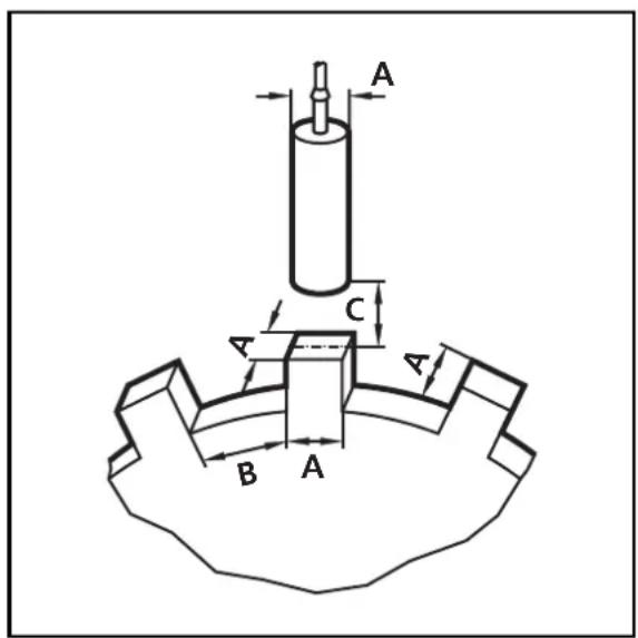
Mounting of the pulse pick-ups:
Adhere to the mounting instructions of the manufacturer.
For optimum functioning of inductive switches the following dimensions should be adhered to:
- B = 2 × A
• C = 12 × S_n
4. Electrical connection

The unit must only be connected by an electrician.
The national and international regulations for the installation of electrical equipment must be observed.
Avoid contact with voltages.
Disconnect the plant from power before wiring. Check if the relays are connected to voltages of external power supplies.
Observe the usual ESD protection measures.
In order to avoid malfunction caused by interference, lay the sensor cable separately from the load cable. Max. length of the sensor cable: 500m.
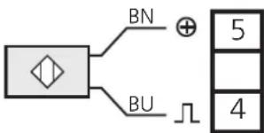
Terminal connection:
| D100 with switched-mode power supply | D100 with transformer power supply |
 |  |
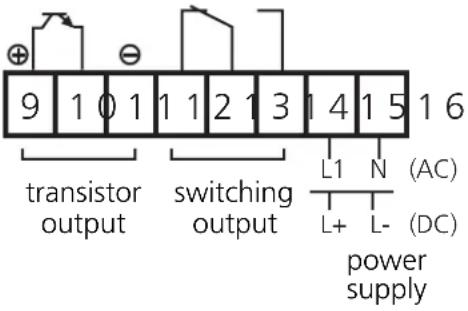 | 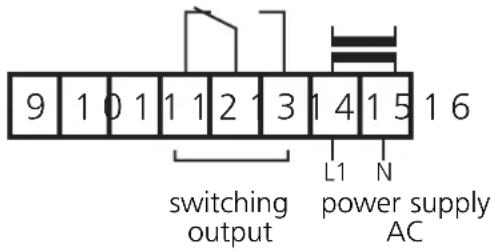 |
Power supply
Power supply either
- at terminals 15 and 16 (AC/DC; for D100 with switched-mode power supply; AC for D100 with transformer power supply)
• or at terminals 6 and 7 (24 V DC).
For DC units the supply voltage must be protected externally.
The terminals of the DC supply are directly linked with the terminals of the pulse pick-up supply. This is why the SELV criteria must be adhered to for DC supply (protective low voltage, circuit galvanically separated from other circuits, not earthed).
If the DC circuit is to be earthed (e.g. because of national regulations), the PELV criteria have to be adhered to (protective low voltage, circuit galvanically separated from other circuits).
If the unit is supplied with AC voltage, the low voltage supply for the pulse pick-up meets the SELV criteria.
The device shall be supplied from an isolating source and protected by an over-current protection device such that the limited voltage circuit requirements in accordance with UL 508 are met.
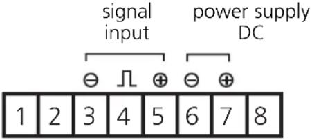
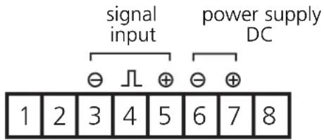
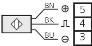
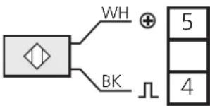
Connection of pulse pick-ups
D 100 provides approx. 24V DC (max. 30 mA) for the supply of pulse pick-ups. Pulse pick-ups which need higher voltage/higher current consumption must have an external supply. In this case the reference point of the external voltage must be connected to terminal 6; the positive pole of the external power supply must not be connected with the D 100.
Please also adhere to the SELV criteria for the pulse pick-up connection so that there is no dangerous contact voltage at the sensor which can enter the unit!
| 3-wire DC PNP 2-wire | DC quadronorm AC / DC | mechanical switch | |
 |  |  | 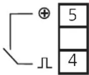 |
5. Setting
5. 1. Setting of the switching function
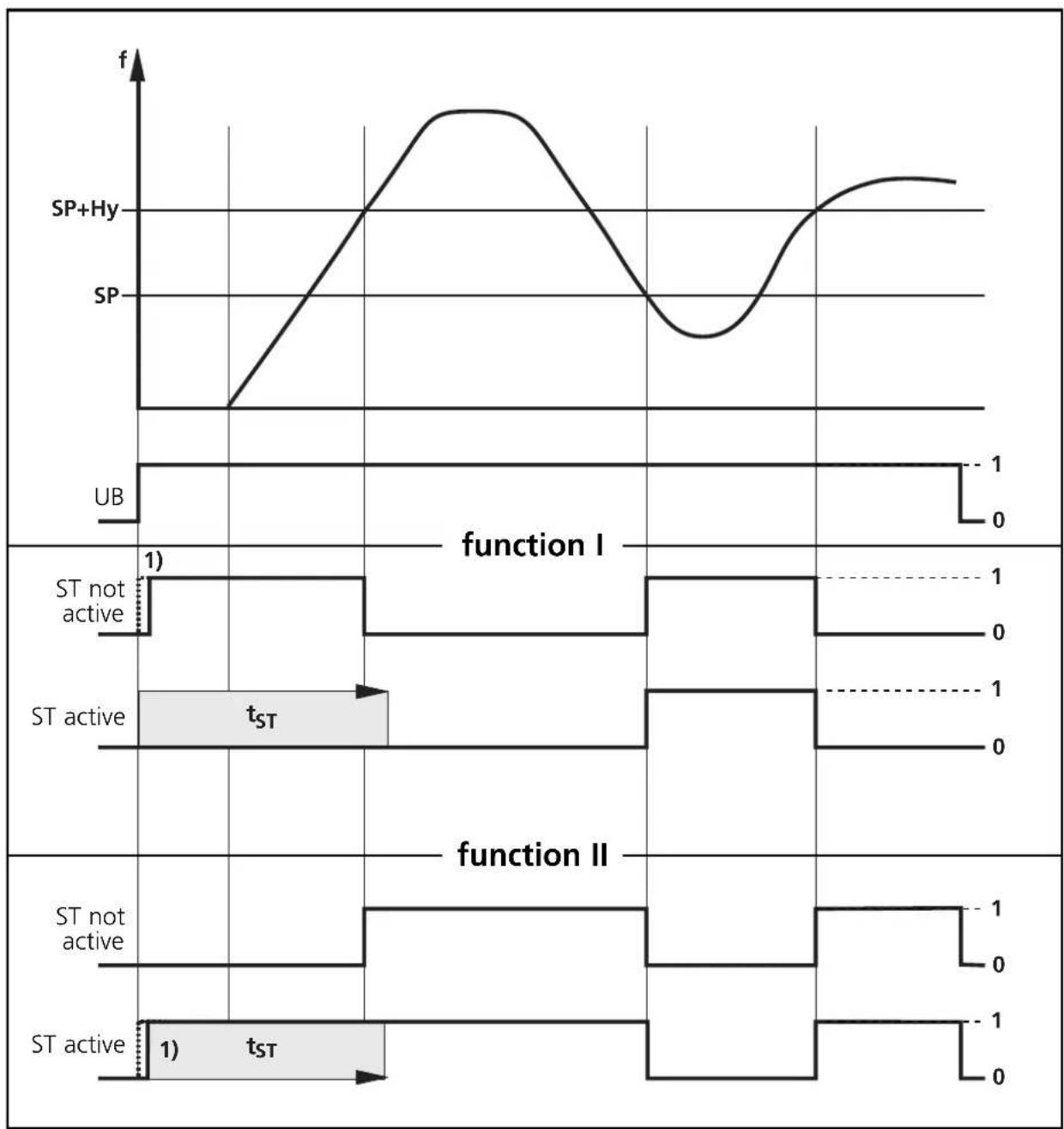
Selection is done with switch (7), there are 4 functions:
| I | Operating state: minimum rotational speed reached / standstill |
| The output relay energises when the input frequency (pulses/min) becomes lower than the set switch point (SP). If the input frequency becomes higher again, the relay switches back at the switch point + hysteresis (SP+Hy). The output relay is de-energised during the start-up delay and as long as the input frequency is higher than the set switch point. | |
| II | Fault state: below minimum rotational speed |
| The output relay de-energises when the input frequency (pulses/min) becomes lower than the set switch point (SP). If the input frequency becomes higher again, the relay switches back at the switch point + hysteresis (SP+Hy). The output relay is energised during the start-up delay and as long as the input frequency is higher than the set switch point.. | |
| III | Operating state: maximum rotational speed reached |
| The output relay energises when the input frequency becomes higher than the set switch point + hysteresis (SP+Hy). If the input frequency becomes lower again, the relay switches back at the switch point (SP). The output relay is de-energised during the start-up delay and as long as the input frequency is lower than the set switch point + hysteresis. | |
| IV | Fault state: rotational speed exceeded |
| The output relay de-energises when the input frequency becomes higher than the set switch point + hysteresis (SP+Hy). If the input frequency becomes lower again, the relay switches back at the switch point (SP). The output relay is energised during the start-up delay and as long as the input frequency is lower than the set switch point + hysteresis. |
Relay energised = transistor output conductive, relay de-energised = transistor output blocked.
5.2. Setting of the switch point
Set the basic value with pot (2), the multiplication factor with switch (8).
| position pot (2) | × | switch (8) | = | switch point (pulses/min) |
| 5 ... 50 / 10 ... 100 | × | 1 | = | 5 ... 50 / 10 ... 100 |
| 5 ... 50 / 10 ... 100 | × | 10 | = | 50 ... 500 / 100 ... 1.000 |
| 5 ... 50 / 10 ... 100 | × | 100 | = | 500 ... 5.000 / 1.000 ... 10.000 |

For low switch points the D 100 recognises changes of the actual value only after a reaction time (which depends on the interval between two successive pulses). This particularly applies to the switching functions I and II. For these functions the reaction time is about 12s in case of a switch point of 5 pulses/min and about 1.2s in case of a switch point of 50 pulses/min.
5. 3. Setting the hysteresis
The hysteresis determines the difference between switch-on point and switch-off point (switch-on point = the output changes its switching state, switch-off point = the output switches back to the previous state).
With pot (3) the hysteresis can be set continuously to the factor 1.05 ... 2 (which corresponds to 5 ... 100% of the switch point).
With unequal distances between cams different times between two successive pulses are measured. They can be above or below the switch point so that the output continuously changes its switching state. By increasing the hysteresis factor this can be prevented.
5. 4. Setting the start-up delay
The start-up delay suppresses an error signal as long as the machine is in the process of starting and has not yet reached its nominal speed.
- Continuous setting between 0.5 and 15s by turning the pot (1).
- After application of the operating voltage the start-up delay is active only once. If the drive is often turned on and off, couple the supply voltage of the drive and the monitor. By doing so, the start-up delay is active every time the drive is turned on.
Function diagram for switching functions I and II
line
| Function | State | Time (s) | |----------|-------------|----------| | function I | ST not active | 1 | | function I | ST active | tST | | function II | ST not active | 1 | | function II | ST active | tST |1) power-on delay time ST = start-up delay
Function diagram for switching functions III and IV
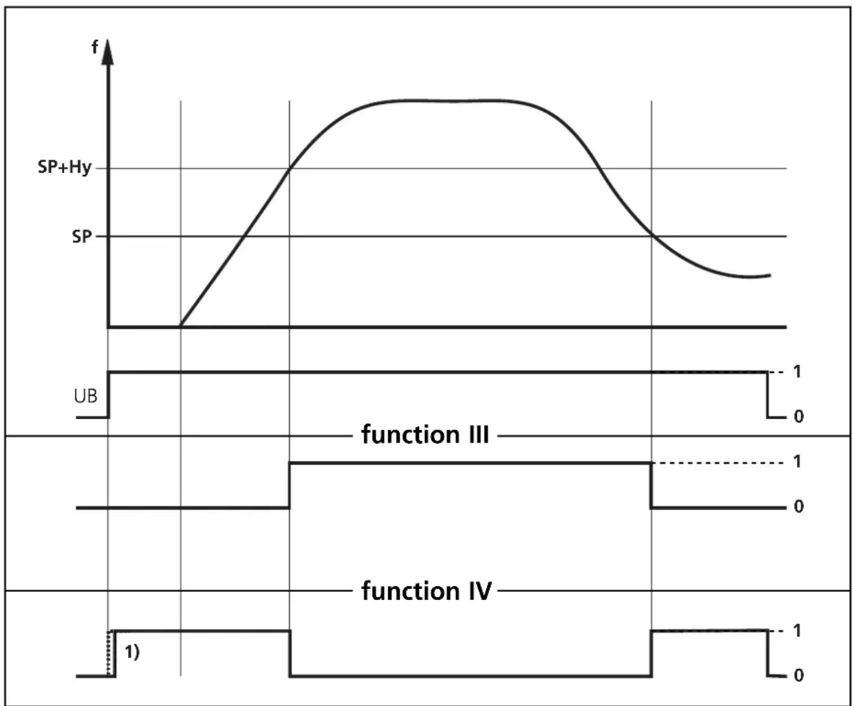
1) 1) power-on delay time
6. Commissioning / operation
After mounting, wiring and setting check whether the unit operates correctly.
7. Maintenance, repair, disposal
In case of correct use no maintenance measures are necessary.
Depending on the switching rate to be expected and the load to be switched, we recommend testing the relay contacts.
Only the manufacturer is allowed to repair the unit.
After use dispose of the unit in an environmentally friendly way according to the valid national regulations.
8. Technical data
| Power supply (AC or DC) |
| DC supply for all units:24 Volt DC ± 10% , at the terminals 6 (-) and 7(+).An external DC voltage supply must meet the SELV requirements.For this supply voltage the unit is classified in protection class 3.Current consumption max. 70mA.For AC units with transformer power supply:According to the type label AC voltage ± 10% at the terminals 15 (L1) and 16 (N), frequency range 50 ... 60 Hz.For this supply the unit is classified in protection class 2 except for the terminal blocks.The protective low voltage generated within the unit for the monitor supply and pulse pick-up supply meets the SELV criteria according to overvoltage category 2 and soiling degree 2.Power consumption max. 5 VA.For units with AC/DC switched-mode power supply:According to the type label AC voltage ± 10% at the terminals 15 and 16,frequency range 50 ... 60 Hz.For this supply the unit is classified in protection class 2 except for the terminal blocks.The protective low voltage generated within the unit for the monitor supply and pulse pick-up supply meets the SELV criteria according to overvoltage category 2 and soiling degree 2.Power consumption max. 5 VA. |
| Inputs |
| Terminal 4 for pnp switching 24 V DC pulse pick-ups.Current consumption: approx. 10 mA.Switch point for pnp pulse pick-up: ≥ 14 V ON;< 7 V OFFThe maximum input frequency to be detected is 250 Hz (corresponds to 15 000 pulses/min).Pulse pick-up supplyVoltage: typ. 24 V DC; current rating: max. 30 mA, protected against short circuit and overload.For external DC supply of the unit via the terminals 6 and 7 the supply voltage of the pulse pick-up corresponds to the DC supply voltage, less a low voltage for the short-circuit protection.For external supply of the unit via the transformer or switched-mode power supply (terminals 15 and 16) the supply voltage of the pulse pick-up corresponds to the rectified non-stabilised output DC voltage of the internal transformer (nominal 24 V). |
| Outputs |
| Output relaySwitching capacity: max. 250V AC, 8 A. The current has to be limited to these values by appropriate external measures. For inductive loads the relays must be subjected to external interference suppression.The relay contacts are safely separated from the supply voltages of the unit, from the sensor and contacts of the second relay, if there is any, up to a rated voltage of 250 V AC.They conform to the overvoltage category 2 and soiling degree 2.NOTE: If the relay is used to switch very low currents (e.g. plc inputs),considerable contact resistance can arise. The life of the relay contacts is considerably reduced by excess current or by the switching of unprotected inductive loads. |
| Transistor output (D100 with AC/DC switched-mode power supply)PNP, 24 V DC ( ± 20%), 200 mA, external supply at terminal 9.The voltage of the short-circuit protected transistor output is switched to terminal 10 depending on the selected function. It is not allowed to apply external voltage to terminals 10 and 11. |
| Unit data |
| Dimensions: 75 x 55 x 110 (H / W / D), weight: max. 400gProtection rating housing: IP 40, protection rating terminals: IP 20Connection: 16 terminals, wire cross section: max: 2.5mm ^2 |
| Environmental conditions |
| Permissible ambient temperature: -20°C ... +60°C in open airHumidity: max. 75% up to +35°C, non condensingAir pressure: 75 KPa to 106 KPaMaximum operating altitude: 2000m above sea level |
| CE marking |
| The unit has the CE mark which is necessary for the free exchange of good within Europe. It shows that the unit meets the requirements according to the accepted general protective purposes. In particular it shows the conformity with the following guidelines:EMC guideline EMC 89/336/EEC,stipulated in the standards EN 60947-5-2 annex X(The user is responsible for the interference suppression of the relay circuit according to the standard).Low voltage guideline LV 73/23/EEC,stipulated in the standard EN61010:1993 + A2:1995Other requirements, e.g. concerning the EC guideline for machines, are to be considered by the user in his planned application and are not part of the certificate of conformity. |
| Notes on the cULus certification (DD0116 and DD0122) |
| According to the certification the above-mentioned units correspond to the following technical data:Nominal voltage AC/DC:DD0116: 110...240 V (50...60 Hz)DD0122: 27...60 V (50...60 Hz)Tolerance: -20...+10%Nominal voltage DC:All above-mentioned units27 V (typ. 24 V), Tolerance: -20...+10%Contact rating:According to cULus classification 6 A (250 V AC), B300, R300Test conditions:Housing dimensions for the temperature-rise test 200 x 200 x 150 mm.Connection terminals:Up to 2.5 mm 2 ; AWG 14 |
La notice d'emploi
- The operating instructions
- Safety instructions
- Function and features
- Mounting
- Mounting of the pulse pick-ups:
- Electrical connection
- Terminal connection:
- Power supply
- Connection of pulse pick-ups
- Setting
- 1. Setting of the switching function
- Setting of the switch point
- 3. Setting the hysteresis
- 4. Setting the start-up delay
- Commissioning / operation
- Maintenance, repair, disposal
- Technical data
- La notice d'emploi
Brand : IFM
Model : DD0121
Category : Electronic assessment system