USER MANUAL EVox J8 RCF
This symbol (a flash of lightning inside an equilateral triangle) alerts the user to the presence of uninsulated parts inside the unit having avoltage which
is sufficiently high to constitute a risk of electric shock.
This symbol (an explanation point inside an equilateral triangle) alerts the user to the presence of important instructions for installation, operation, and maintenance.
SAFETY FIRST!
Before installing and using this RCF product, please read this instruction manual carefully and keep it on hand for future reference.
WARNING!
This product has been designed for installation by qualified personnel having the technical know how and experience or specific instructions to ensure correct execution of all the operations involved and to prevent any risk to personal safety. There are numerous factors that must be taken into consideration when installing a professional sound system, including mechanical and electrical evaluations as well as studies related to coverage and acoustic performance.
BCF therefore strongly recommends that you have this product installed by professional installers or specialized firms.
-
ATTENTION TO THE PRECAUTIONS Always follow the precautions provided on this BCF product and in the instruction manual.
-
WATER AND HUMIDITY - Do not use this BCF product near water r ; for example, in the vicinity of a bath tub or sink, in a damp cellar, near a swimming pool, etc., except expressly allowed.
-
VENTILATION – (Electronic and powered products) Situate this RCF product in a place that is well-ventilated and not exposed to direct sunlight. Do not jeopardize the effectiveness of the cooling systems in any way. Never situate the unit inside completely closed structures, which would impede the flow of air through the vents.
-
HEAT - Situate this RCF product far from any heat source such as radiators or any other r device that produces heat.
-
POWER SUPPLY - Only convert this BCF product to a power source of the type indicated on the product itself. If an external direct current (DC) power supplier or a battery is being used, make sure that the voltage of the power source corresponds to the range indicated on the product and that the connections respect the pole rity (+/-).
-
INSTALLATION - Do not install and use this product in any way that is not provided for in the instruction manual.
-
POWER CABLE PROTECTION - Lay the power cable in points where it cannot be stepped on or crushed by other objects, paying particular attention to the parts of the cable near the connectors.
-
FOREIGN BODIES AND LIQUIDS - Be careful not to allow any foreign bodies or liquids to get into the product.
-
TECHNICAL SERVICE - The user should never attempt to make any repairs on this BCF product unless otherwise indicated in the instruction manual. Repairs should be mainly made only by qualified service technicians in the following cases:
A. The power cable has been damaged.
B. Foreign bodies or liquids have got into the product. C. The product has been exposed to rain.
D. The product does not function normally, or shows a marked decrease in performance.
E. The product has fallen or its chassis/enclosure has been damaged.
-
RESPECT THE SAFETY STANDARDS The entire sound system must be created in compliance with the current standards and laws regarding electrical systems.
-
SPECIFICATIONS - When installing and using this product, keep in mind the technical specifications indicated in the dedicated section of the instruction manual.
-
ACCESSORIES - Install and use this product only with the accessories specified by the manufacturer or supplied with the product.
HEARING LOSS
Exposure to high sound levels can cause permanent hearing loss. The sound pressure level which leads to hearing loss varies considerably from one person to another, and depends on the duration of exposure. To prevent potentially dangerous exposure to high sound pressure levels, anyone subjected to such levels must use suitable protection.
OPERATING PRECAUTIONS
- Do not use solvent, alcohol, benzene,
or other volatile substance v. for cleaning the external parts of the product.
-
Do not use the speaker r in tropical climates.
-
If the product is used in particularly cold places, drive it with a low signal for 5-10 minutes before using it at maximum power.
WARNING: If the device is marked with this symbol (fig.1) it must not be disposed of along with natural domestic waste. It is electrical or electronic equipment that is required by law; in accordance with European Directives (2002/95 / EC, 2002/96/EC and 2003/108/E C), to be disposed of sepa rately. The black bar located under the symbol indicates that the product was put on the market after August 13, 2005.
- EUROPEAN UNION Electrical and electronic equipment must be managed separately and in accordance with legislation that requires appropriate treatment, recovery and recycling of the above mentioned products.
Illegal disposal is subject to the penalties of line.
Domestic waste
As a result of the provisions put into effect by the Member States, private residents in the EU can transfer used electrical anal/or electronic devices to designated separate waste collection centres free of charge (*). Local retailers can also collect old products free of charge if the user purchases a new, similar product.
Business waste
In this case, waste recovery is organized in each State by the RCF supplier, in some European countries it is RCF itself; in others it is the national importer.
Contact the RCF retailer who will have the information necessary for product recovery. Designated separate waste collection centres are also available for this type of waste (*).
If the used electrical and/or electronic equipment contains battle ries and/or accumulates, the user must dispose them separately beforehand. In accordance with local regulations. Proper disposal of these products will help ensure that the waste undergoes the necessary treatment, recovery and recycling and prevents the potentially negative impact on the environment.
as well as on human health that could derive from improper waste management.
(*) For more information contact the local retailer or the local enforcement body. Some organizational aspects on recovery and disposal of this type of waste may not be identical throughout the EU, as they are put into effect in the detailed decrees of the single States.
2. COUNTRIES THAT ARE NOT PART OF THE EUROPEAN UNION
Contact the local authorities to find out about the proper disposal method for this product.
FR AVVERTISSEMENTS
Class 1 Earth "WARNING"
Norway: Apparatet må kun tilkoples jordet stikkontakt.
OWNER MANUAL MANUALE D'USO
EVOX J8
- PROFESSIONAL ACTIVE TWO-WAY ARRAY
- DIFFUSORE ACUSTICO ("ARRAY")
AMPLIFICATO A DUE VIE
IMPORTANT
Before connecting and using this product, please read this instruction manual carefully and keep it on hand for future reference.
The manual is to be considered an integral part of this product and must accompany it when it changes ownership as a reference for correct installation and use as well as for the safety precautions.
RCF S.p.A. will not assume any responsibility for the incorrect installation and / or use of this product.
WARNING: To prevent the risk of fire or electric shock, never expose this product to rain or humidity.
CAUTION: to prevent electric shock hazard, do not connect to mains power supply while grille is removed
SAFETY PRECAUTIONS
- All the precautions, in particular the safety ones, must be read with special attention, as they provide important information.
2. POWER SUPPLY FROM MAINS
- Appliance coupler or PowerCon Connector® is used to disconnect device from MAIN power. This device shall remain readily accessible after the installation
- The mains voltage is sufficiently high to involve a risk of electrocution: never install or connect this product when its power cord is plugged in.
- Before powering up, make sure that all the connections have been made correctly and the voltage of your mains corresponds to the voltage shown on the rating plate on the unit, if not, please contact your RCF dealer.
- The metallic parts of the unit are earthed by means of the power cord. This is a Class I device and for its use it must be connected to a grounded power source.
- Protect the power cord from damage. Make sure it is positioned in a way that it cannot be stepped on or crushed by objects.
-
To prevent the risk of electric shock, never open this product: there are no parts inside that the user needs to access.
-
Make sure that no objects or liquids can get into this product, as this may cause a short circuit. This apparatus shall not be exposed to dripping or splashing. No objects filled with liquid (such as vases) and no naked sources (such as lit candles) should be placed on this apparatus.
-
Never attempt to carry out any operations, modifications or repairs that are not expressly described in this manual.
Contact your authorized service centre or qualified personnel should any of the following occur:
- The product does not function (or functions in an anomalous way).
- The power cord has been damaged.
- Objects or liquids are inside the product.
-
The product has been subject to a heavy impact.
-
If this product is not used for a long period, disconnect its power cord.
-
If this product begins emitting any strange odours or smoke, switch it off immediately and disconnect its power cord.
-
Do not connect this product to any equipment or accessories not foreseen.
Do not try to hang this product by using elements that are unsuitable or not specific for this purpose.
IMPORTANT

WARNING

CAUTION

To prevent the risk of falling equipment, do not stack multiple units of this product unless this possibility is specified in the user manual.
- RCF S.p.A. strongly recommends this product is only installed by professional qualified installers (or specialised firms) who can ensure correct installation and certify it according to the regulations in force.
The entire audio system must comply with the current standards and regulations regarding electrical systems.
- Supports and trolleys
The equipment should be only used on trolleys or supports, where necessary, that are recommended by the manufacturer. The equipment / support / trolley assembly must be moved with extreme caution.
Sudden stops, excessive pushing force and uneven floors may cause the assembly to overturn.
- Hearing loss
Exposure to high sound levels can cause permanent hearing loss. The acoustic pressure level that leads to hearing loss is different from person to person and depends on the duration of exposure. To prevent potentially dangerous exposure to high levels of acoustic pressure, anyone who is exposed to these levels should use adequate protection devices.
When a transducer capable of producing high sound levels is being used, it is therefore necessary to wear ear plugs or protective earphones. See the manual technical specifications to know the maximum sound pressure level.
- Situate this product far from any heat sources and always ensure adequate air circulation around it.
- Do not overload this product for a long time.
- Never force the control elements (keys, knobs, etc.).
- Do not use solvents, alcohol, benzene or other volatile substances for cleaning the external parts of this product.
Use a dry cloth.
- Do not put microphones close and in front of speakers, in order to avoid audio feedback ('Larsen effect').
NOTES ABOUT AUDIO SIGNAL CABLES

To prevent the occurrence of noise on microphone / line signal cables, use screened cables only and avoid putting them close to:
- Equipment that produces high-intensity electromagnetic fields.
- Mains cables.
- Loudspeaker lines.
The equipments considered in this manual can be used in electromagnetic environment E1 to E3 as specified on EN 55103-1/2: 2009.
FCC NOTES

Note: This equipment has been tested and found to comply with the limits for a Class A digital device, pursuant to Part 15 of the FCC Rules. These limits are designed to provide reasonable protection against harmful interference when the equipment is operated in a commercial environment. This equipment generates, uses, and can radiate radio frequency energy, and if it is not installed and used in accordance with the instruction manual, it may cause harmful interference to radio communications. Operation of this equipment in a residential area is likely to cause harmful interference, in which case the user will be required to correct the interference at his own expense.
Modifications: Any modifications made to this device that are not approved by RCF may void the authority granted to the user by the FCC to operate this equipment.
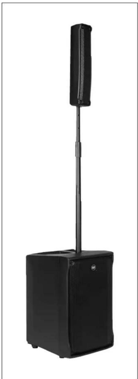
EVOX J8 is a portable active sound system (made of a satellite plus a subwoofer) that combines quality and reliability of RCF transducers with high amplification power.
It features eight 2.0" full range transducers in the line source satellite and a deep sounding 12" woofer in a bass reflex enclosure.
The system is an optimal portable solutions for live music, DJ mix-sets and also presentations, congresses, other events, etc. .
INNOVATIVE DSP PROCESSING
EVOX DSP processing is the result of many years of experience in line array design combined with innovative and dedicated algorithms. Thanks to the frequency dependent drivers excursion and control of distortion, EVOX DSP processing is capable to guarantee a high output from these small systems. A dedicated vocal processing has been specifically studied for speech reproduction during presentations or conferences.
RCF TECHNOLOGY
EVOX J8 includes high technology RCF transducers.
The ultra-compact full-range 2" driver can handle extremely high sound pressure levels and power. The high excursion woofers are able to extend to the lowest frequencies and offer a quick and precise response up to the crossover point.
Specific attention has been dedicated to mid-low frequencies as well.
CONTROLLED DIRECTIVITY PATTERN
EVOX array design features a constant horizontal directivity coverage of 120^ , offering a perfect listening experience to the audience.
The vertical array design is progressively shaped to guarantee a correct listening from the first row.
MULTIFUNCTIONAL TOP HANDLE
The top steel plate joins the handle and the insert for pole mounting.
A rubber hand grip has been added for great portability.
CLASS D AMPLIFICATION
EVOX J8 includes a high power two-way class D amplifier with DSP controlled crossover.
natural_image
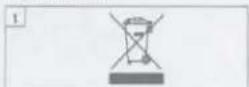
Close-up of a mechanical housing component with mounting holes and a central vertical slot (no visible text or symbols)
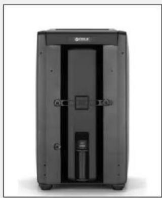
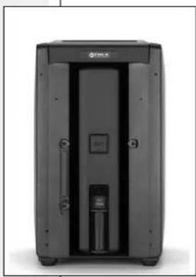
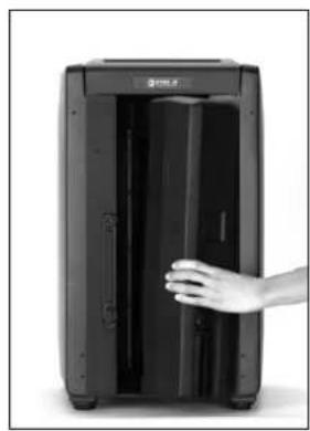
Remove the rubber band and take out the satellite
natural_image
Exterior view of a black industrial device with control panel and side-mounted unit (no visible text or symbols)
natural_image
Exterior view of a black industrial device with control panel and door (no visible text or symbols)
natural_image
Black electronic device with open door and hand reaching out (no visible text or symbols)
Screw the lower part of the satellite speaker stand (the pole) into the subwoofer insert for pole mounting.

natural_image
Close-up of a hand holding a cylindrical object above a tray, no visible text or symbols
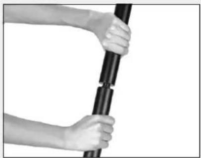
Screw the central part of the satellite speaker stand into its lower part.
natural_image
Close-up of hands holding a black cylindrical object, possibly a pole or lever (no text or symbols visible)
Loose the stand bolt, adjust the satellite speaker height from the floor and tighten the bolt again, then insert the satellite speaker into its complete stand and aim it correctly.
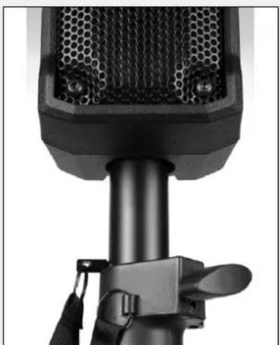
natural_image
Close-up of a black desktop microphone with mesh grille and adjustable handle (no visible text or symbols)
natural_image
Black outdoor stand with vertical screen and rectangular base (no text or symbols visible)
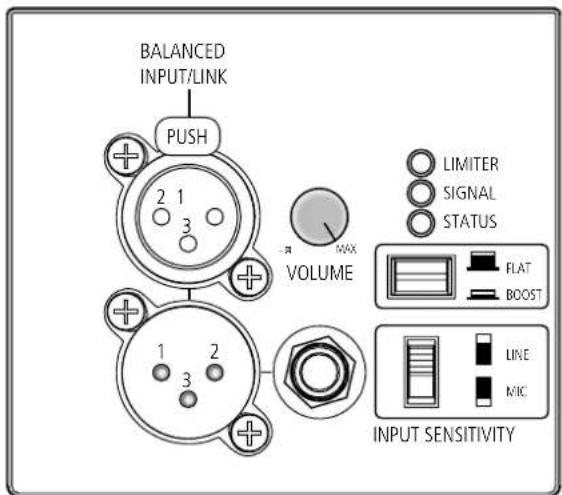
1/4" TRS JACK CONNECTOR
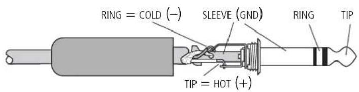
BALANCED CONNECTION
TIP: + HOT
RING: -COLD
SLEEVE: GND
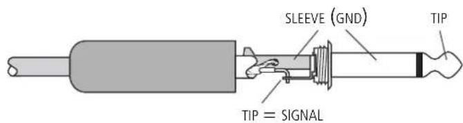
UNBALANCED CONNECTION
TIP: SIGNAL
SLEEVE: GND
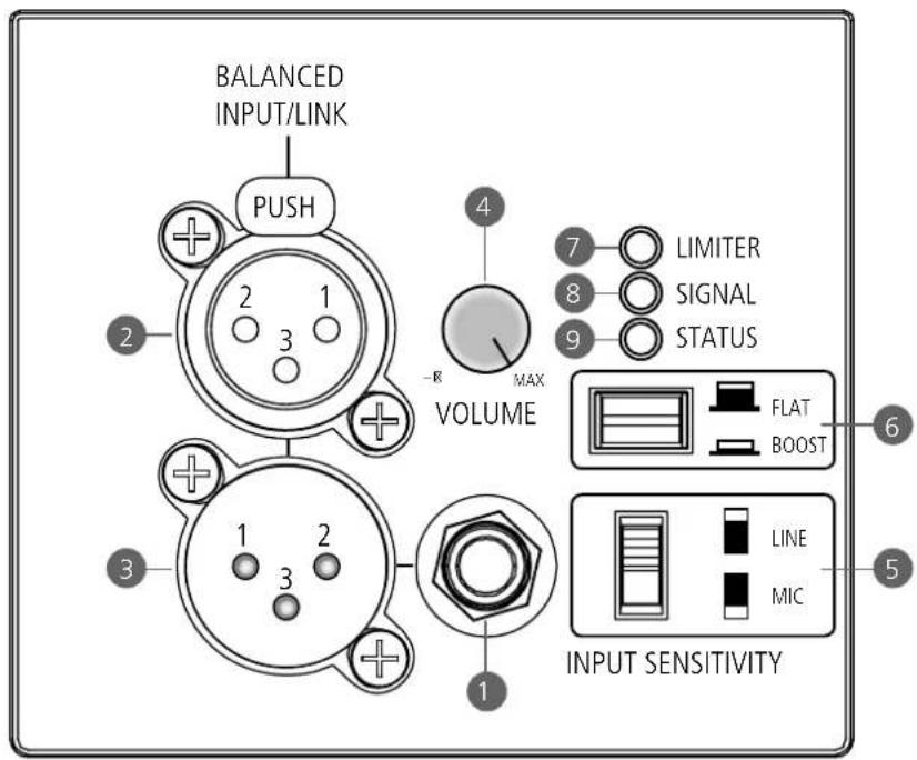
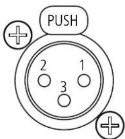
Female XLR connector
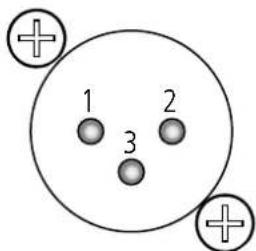
Male XLR connector
3 Balanced parallel audio output (male XLR connector).
This output is linked in parallel with the audio input and is useful to connect another speaker.

XLR PINS:
1 GROUND, 2 AUDIO SIGNAL (+ , HOT),
3 AUDIO SIGNAL (—, COLD).
4 Amplifier volume control
5 Input sensitivity switch
LINE (normal mode): the input sensitivity is set to LINE level (+4 dBu), suitable for a mixer output.
MIC: the input sensitivity is set to MIC level, suitable for the direct connection of a dynamic microphone. Do NOT use this setting when connected to a mixer output!
6 FLAT / BOOST switch
FLAT (released switch, normal mode): no equalisation is applied (flat frequency response).
BOOST (pushed switch): 'loudness' equalisation, only recommended for background music at low volume levels.
7 LIMITER LED
The internal amplifier has a limiter circuit to prevent clipping and overdriving transducers. It blinks when the signal level reaches the clipping point, causing the limiter intervention. If it is steady lit, the input signal level is excessive and should be reduced.
8 SIGNAL LED
When lit, it indicates the signal presence at the audio input.
9 STATUS LED
When blinking, it indicates the internal protection intervention due to thermal drift (the amplifier is muted).
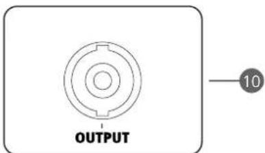
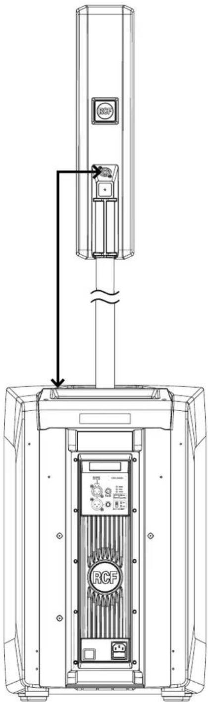
10 Amplifier output to link the satellite speaker.
IMPORTANT:
BEFORE TURNING THE AMPLIFIER ON, LINK THE SUBWOOFER AMPLIFIER OUTPUT TO THE SATELLITE SPEAKER INPUT (AS SHOWN IN THE FIGURE)!

11 POWER switch
Push it to turn ON / OFF the amplifier.
Before switching the amplifier on, check all the connections and turn fully
counterclockwise ( - ) the volume control

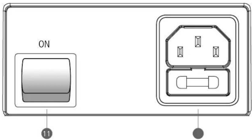

VDE inlet.
100-120V\~ T 6.3 A L 250V
220-240V\~ T 3.15 A L 250V
Before connecting the power cord, check if the A/C power corresponds to the voltage indicated on the rating plate on the unit, if not, please contact your RCF dealer.
Connect the power cord only to a A/C power socket outlet with a protective earthing connection.
When replacing the fuse, refer to the silkscreen indications.
WARNING: the VDE Power Connector is used to disconnect the system from the power supply network. It must be easily accessible after the installation and during the use of the system.
SPECIFICATIONS

ACOUSTICAL
Frequency response
Maximum sound pressure level
Horizontal coverage angle
Vertical coverage angle
Subwoofer transducer
Satellite transducers
AMPLIFIER / DSP
Amplifier power (low frequencies)
Amplifier power (high frequencies)
Input sensitivity (LINE)
Crossover frequency
Protections
Limiter
Cooling
Operating voltage
Inrush current
SUBWOOFER PHYSICAL
Height
Width
Depth
SATELLITE PHYSICAL
Height
Width
Depth
ENTIRE SYSTEM PHYSICAL
Minimum height of the system
Maximum height of the system
Net weight
Cabinet
EVOX J8
40 Hz - 20.000 Hz
128 dB
120°
30^
12", 2.5" voice coil
8 x 2", 1.0" voice coil
1000 W (peak)
400 W (peak)
+4 dBu
220 Hz
thermal drift, RMS
software limiter
convective
115 / 230 V (according to the model), 50-60 Hz
10,1 A (According to EN 55013-1:2009)
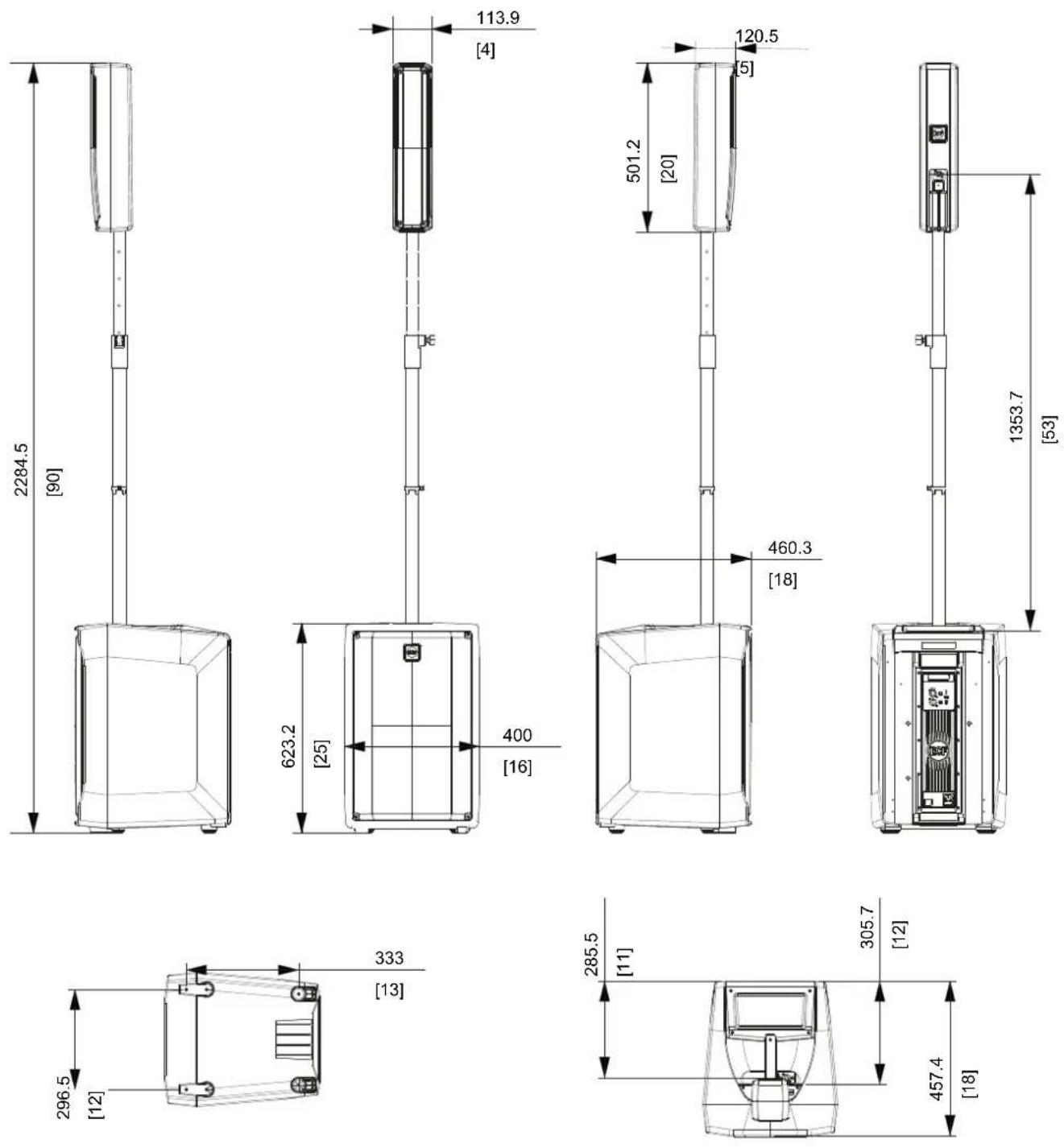
2350 mm (92.5")
350 mm (13.77")
450 mm (17.71")
501,2 mm (19,73")
113,9 mm (4,48")
120,5 mm (4.74")
1974 mm (77,7")
2284 mm (89,9")
23,8 Kg (52,5 lbs)
PP composite
www.rcf.it
RCF S.p.A.
natural_image
Black outdoor stand with vertical cylindrical top and rectangular base (no text or symbols visible)
Description
The RCF J8 features a line source satellite module with eight 2" full-range drivers paired with a high-powered 12" woofer in a bass reflex enclosure. All powered by on-board 1400 W Class D amplification. The EVOX J Series maintains a similar footprint to the original EVOX systems, now in a portable composite enclosure. The system offers stunning sound performance with crystal-clear vocal reproduction and unparalleled musical response.
Features
128 dB Max SPL
1400 Watt 2-way power
DSP Processing with FiRPHASE
12" woofer, high power 2.5" voice coil
8 x 2" ultra compact fullrange 1.0" voice coil
2350x350x450 mm 92.5x13.77x17.71 in (HxWxD)
23.8/52.5 kg/lbs
Part Number
| 13000554 | EVOX J8 | 220-240 V | Black | EAN 8024530015541 |
| 13000555 | EVOX J8 | 115 V | Black | EAN 8024530015558 |
| 13000567 | EVOX J8 W | 220-240 V | White | EAN 8024530015589 |
| 13000568 | EVOX J8 W | 115 V | White | EAN 8024530015596 |
Line Art 2D
![333.1 [13] 296.5 [2] 2285 [90] 623.2 [25] 400 [16] 289.6 [11] 285.5 [11.2] 501.2 [20] 460.26 [18.1] 1340.6 [33] SPEAKER EVOX JB 220-240V REV. A W74 30 / 30 V40V](/content/2026/04/591060/images/f76efedea2dd71cec625a0cc58348b5ea8119f3208e3a87f0cd68b06d493bf2f.jpg)
Acoustical specifications
Transducers
Input/Output section
Processor section
Power section
Standard compliance
Physical specifications
TECHNICAL SPECIFICATIONS
| Frequency Response | 40 Hz ÷ 20000 Hz |
| Max SPL @ 1m | 128 dB |
| Horizontal coverage angle | 120° |
| Vertical coverage angle | 30° |
| Fullrange | 8 x 2.0", 1.0" v.c |
| Woofer | 1 x 12", 2.5" v.c |
| Input signal | bal/unbal |
| Input connectors | XLR, Jack |
| Output connectors | XLR |
| Input sensitivity | -2 dBu/+4 dBu |
| Crossover Frequencies | 220 Hz |
| Protections | Thermal, RMS |
| Limiter | Soft Limiter |
| Controls | Volume, Boost, Mic/Line |
| Total Power | 1400 W Peak, 700 W RMS |
| High frequencies | 400 W Peak, 200 W RMS |
| Low frequencies | 1000 W Peak, 500 W RMS |
| Cooling | Convection |
| Connections | VDE |
| Safety agency | CE compliant |
| Cabinet/Case Material | PP Composite |
| Handles | 1 Top |
| Grille | Steel |
| Color | Black, White |
| Height | 2285 mm / 89.96 inches |
| Width | 400 mm / 15.75 inches |
| Depth | 460 mm / 18.11 inches |
| Weight | 20.2 kg / 44.53 lbs |
Protections
ACCESSORIES
COVERS
13360407 CVR EVOX J
13360406 CVR-WH EVOX J
Cables
CABLES KIT
13360102 AC XLR 3M3F
EAN 8024530015725
EAN 8024530015718
EAN 8024530006402
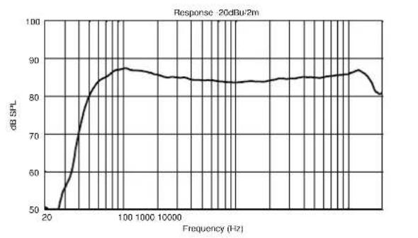
ACOUSTIC MEASUREMENTS
line
| Frequency (Hz) | dB SPL |
| -------------- | ------ |
| 20 | 50 |
| 100 | 88 |
| 1000 | 87 |
| 10000 | 85 |
| 100000 | 84 |
| >10000 | 83 |
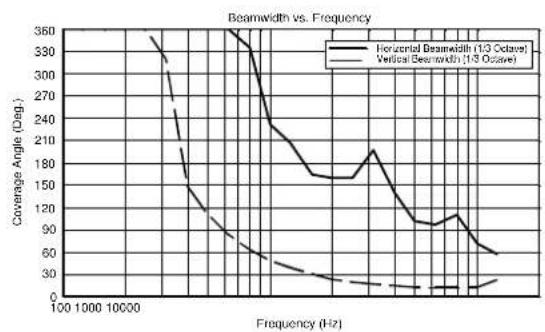
line
| Frequency (Hz) | Horizontal Beamwidth (1/3 Octave) | Vertical Beamwidth (1/3 Octave) |
| -------------- | --------------------------------- | ------------------------------- |
| 100 | 350 | 350 |
| 1000 | 300 | 270 |
| 10000 | 250 | 200 |
| 2000 | 200 | 150 |
| 500 | 150 | 100 |
| 1000 | 100 | 50 |
| 2000 | 50 | 25 |
| 5000 | 25 | 10 |
| 10000 | 10 | 5 |
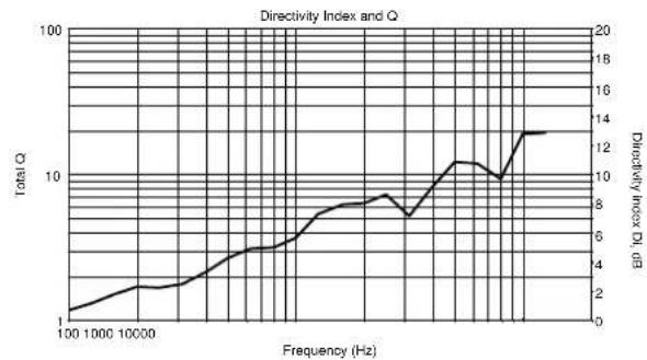
line
| Frequency (Hz) | Total Q | Directivity Index Df, dB |
| -------------- | ------- | ------------------------ |
| 100 | 1 | 0 |
| 1000 | 2 | 2 |
| 10000 | 3 | 4 |
| 100000 | 5 | 6 |
| 1000000 | 8 | 8 |
| 10000000 | 12 | 12 |
| 100000000 | 14 | 14 |
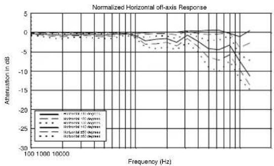
line
| Frequency (Hz) | Attenuation in dB |
| -------------- | ----------------- |
| 100 | 0 |
| 1000 | -5 |
| 10000 | -10 |
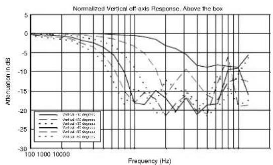
line
| Frequency (Hz) | Attenuation in dB (Vertical -10 degrees) | Attenuation in dB (Vertical -25 degrees) | Attenuation in dB (Vertical -35 degrees) | Attenuation in dB (Vertical -45 degrees) | Attenuation in dB (Vertical -55 degrees) |
| -------------- | ---------------------------------------- | ---------------------------------------- | ---------------------------------------- | ---------------------------------------- | ---------------------------------------- |
| 100 | 0 | 0 | 0 | 0 | 0 |
| 1000 | -5 | -5 | -5 | -5 | -5 |
| 10000 | -10 | -10 | -10 | -10 | -10 |
| 100000 | -15 | -15 | -15 | -15 | -15 |
| 1000000 | -20 | -20 | -20 | -20 | -20 |
| 10000000 | -25 | -25 | -25 | -25 | -25 |
| 100000000 | -30 | -30 | -30 | -30 | -30 |
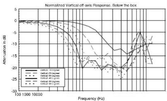
line
| Frequency (Hz) | Attenuation in dB (Vertical off-axis) | Attenuation in dB (Vertical 200000) | Attenuation in dB (Vertical 400000) | Attenuation in dB (Vertical 800000) |
| -------------- | ------------------------------------- | ----------------------------------- | ----------------------------------- | ----------------------------------- |
| 100 | 0 | 0 | 0 | 0 |
| 1000 | -5 | -5 | -5 | -5 |
| 10000 | -10 | -10 | -10 | -10 |
| 100000 | -15 | -15 | -15 | -15 |
| 1000000 | -20 | -20 | -20 | -20 |
| 10000000 | -25 | -25 | -25 | -25 |
| 100000000 | -30 | -30 | -30 | -30 |
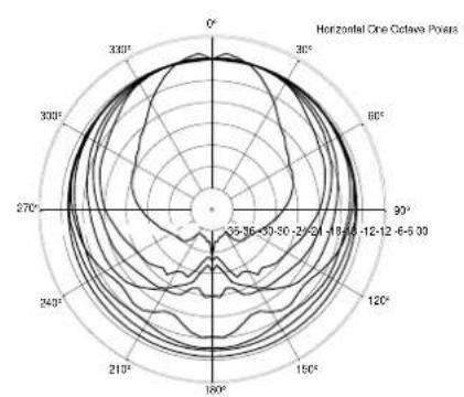
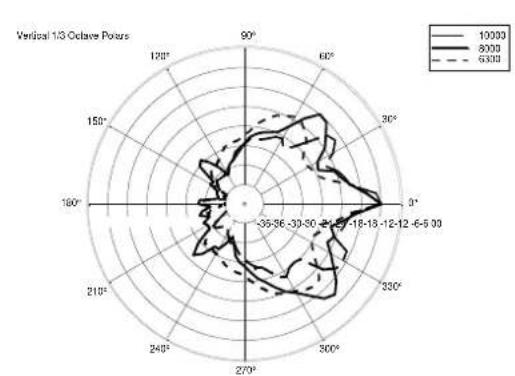
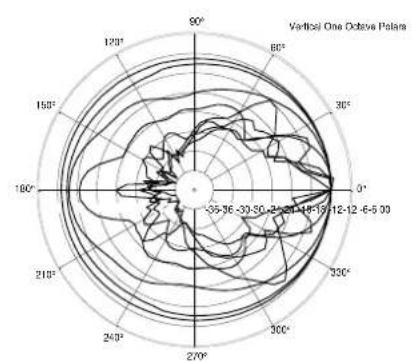
ACOUSTIC MEASUREMENTS
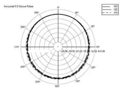
radar
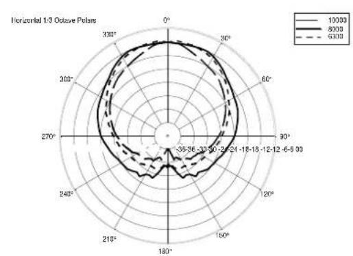
Horizontal 1/3 Octave Polans
| Angle | Value |
|---|---|
| 0° | 160 |
| 30° | 125 |
| 60° | 100 |
| 90° | 100 |
| 12-12-6-5:00 | 125 |
| 150° | 160 |
| 180° | 160 |
| 210° | 125 |
| 240° | 100 |
| 270° | 100 |
| 300° | 125 |
| 330° | 160 |
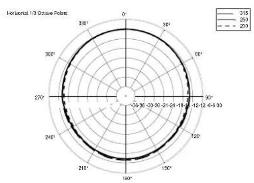
radar
Horizontal 1/3 Osave Poles
| Angle | Value |
|---|---|
| 0° | 315 |
| 30° | 250 |
| 60° | 200 |
| 90° | 315 |
| 120° | 250 |
| 150° | 200 |
| 180° | 315 |
| 210° | 250 |
| 240° | 200 |
| 270° | 315 |
| 300° | 250 |
| 330° | 200 |
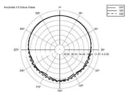
radar
Horizontal 1/3 Octave Polaris
| Angle | 530 | 500 | 400 |
|---|---|---|---|
| 0° | 68 | 62 | 36 |
| 30° | 72 | 68 | 39 |
| 60° | 75 | 72 | 30 |
| 90° | 78 | 75 | 24 |
| 120° | 75 | 72 | 18 |
| 150° | 72 | 68 | 12 |
| 180° | 68 | 62 | 15 |
| 210° | 62 | 58 | 24 |
| 240° | 58 | 52 | 36 |
| 270° | 52 | 48 | 40 |
| 300° | 48 | 42 | 48 |
| 330° | 42 | 38 | 56 |
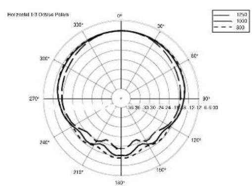
radar
Horizontal 1/3 Octave Polaris
| Angle | 1250 | 1000 | 800 |
|---|---|---|---|
| 0° | 1250 | 1000 | 800 |
| 30° | 1250 | 1000 | 800 |
| 60° | 1250 | 1000 | 800 |
| 90° | 1250 | 1000 | 800 |
| 120° | 1250 | 1000 | 800 |
| 150° | 1250 | 1000 | 800 |
| 180° | 1250 | 1000 | 800 |
| 210° | 1250 | 1000 | 800 |
| 240° | 1250 | 1000 | 800 |
| 270° | 1250 | 1000 | 800 |
| 300° | 1250 | 1000 | 800 |
| 330° | 1250 | 1000 | 800 |
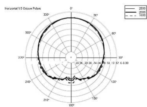
radar
Horizontal 1/3 Octave Polaris
| Angle | 2500 | 2000 | 1500 |
|---|---|---|---|
| 0° | 24.78 | 24.78 | 24.78 |
| 30° | 24.78 | 24.78 | 24.78 |
| 60° | 24.78 | 24.78 | 24.78 |
| 90° | 24.78 | 24.78 | 24.78 |
| 120° | 24.78 | 24.78 | 24.78 |
| 150° | 24.78 | 24.78 | 24.78 |
| 180° | 24.78 | 24.78 | 24.78 |
| 210° | 24.78 | 24.78 | 24.78 |
| 240° | 24.78 | 24.78 | 24.78 |
| 270° | 24.78 | 24.78 | 24.78 |
| 300° | 24.78 | 24.78 | 24.78 |
| 330° | 24.78 | 24.78 | 24.78 |
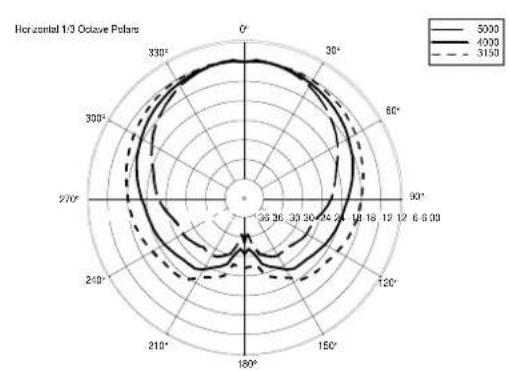
radar
Horizontal 1/3 Octave Polars
| Angle | 5000 | 4000 | 3150 |
|---|---|---|---|
| 0° | 68.2 | 67.9 | 67.6 |
| 30° | 67.5 | 67.2 | 66.9 |
| 60° | 66.8 | 66.3 | 65.8 |
| 90° | 66.1 | 65.6 | 65.1 |
| 120° | 65.4 | 64.8 | 64.2 |
| 150° | 64.7 | 64.1 | 63.5 |
| 180° | 64.0 | 63.3 | 62.7 |
| 210° | 63.3 | 62.6 | 61.9 |
| 240° | 62.6 | 61.9 | 61.1 |
| 270° | 61.9 | 61.2 | 60.4 |
| 300° | 61.2 | 60.5 | 59.7 |
| 330° | 60.5 | 59.8 | 59.1 |
| Right-angle axis (in degrees) | - | - | - |
The chart displays a single data series with values for each angle from 0° to 330° in both directions. The legend indicates three distinct series: solid line for '5000', dashed line for '4000', and dash-dot line for '3150'. The chart is labeled 'Horizontal 1/3 Octave Polars' at the top left.
radar
Horizontal 1/3 Octave Poles
| Angle | 10000 | 8000 | 6300 |
|---|---|---|---|
| 0° | 9500 | 9400 | 9300 |
| 30° | 9200 | 9100 | 9000 |
| 60° | 8800 | 8700 | 8600 |
| 90° | 8400 | 8300 | 8200 |
| 12-15 | 8000 | 7900 | 7800 |
| 15-18 | 7600 | 7500 | 7400 |
| 18-21 | 7200 | 7100 | 7000 |
| 21-24 | 6800 | 6700 | 6600 |
| 24-27 | 6400 | 6300 | 6200 |
| 27-30 | 6000 | 5900 | 5800 |
| 30-33 | 5600 | 5500 | 5400 |
| 33-36 | 5200 | 5100 | 5000 |
| 36-39 | 4800 | 4700 | 4600 |
| 39-42 | 4400 | 4300 | 4200 |
| 42-45 | 4000 | 3900 | 3800 |
| 45-48 | 3600 | 3500 | 3400 |
| 48-51 | 3200 | 3100 | 3000 |
| 51-54 | 2800 | 2700 | 2600 |
| 54-57 | 2400 | 2300 | 2200 |
| 57-60 | 2100 | 2000 | 2100 |
| 61-64 | 1800 | 1750 | 1750 |
| 64-67 | 1550 | 1525 | 1525 |
| 67-70 | 1375 | 1357.5 | 1357.5 |
| 71-74 | 1212.5 | 1212.5 | 1212.5 |
| 74-77 | 1126.5 | 1126.5 | 1126.5 |
| 77-81 | 1126.5 | 1126.5 | 1126.5 |
| 81-84 | 1126.5 | 1126.5 | 1126.5 |
| 84-87 | 1126.5 | 1126.5 | 1126.5 |
| 87-91 | nan | nan | nan |
The chart displays a single data series with values for each direction of the polar axis (e.g., 'O', 'P'). The values are annotated on the chart as follows: 'O' = -35, 'P' = -36, and 'θ' = -39. The chart is divided into three quadrants by a vertical line at θ = -39, indicating the angular position relative to the polar axis. The legend defines three distinct series: solid black for 'O', dashed black for 'P', and dash-dot black for '6333'. The data points are labeled with their respective values along the radial axis.
radar
| Angle (°) | Value |
| --------- | ----- |
| 0 | 125 |
| 30 | 110 |
| 60 | 95 |
| 90 | 80 |
| 120 | 65 |
| 150 | 50 |
| 180 | 35 |
| 210 | 20 |
| 240 | 15 |
| 270 | 10 |
| 300 | 8 |
| 330 | 6 |
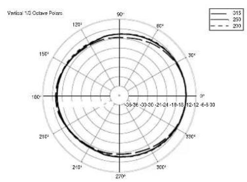
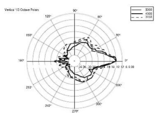
ACOUSTIC MEASUREMENTS
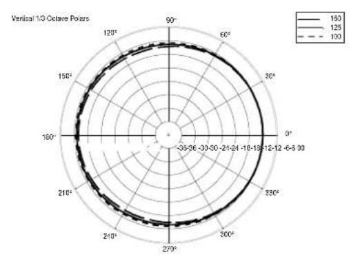
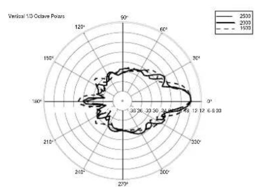
radar
Vertical 1/3 Octave Pours
| Angle | Value |
|---|---|
| 0°-30° | 150 |
| 30°-60° | 125 |
| 60°-90° | 100 |
| 90°-120° | 150 |
| 120°-150° | 125 |
| 150°-180° | 100 |
| 180°-210° | 150 |
| 210°-240° | 125 |
| 240°-270° | 100 |
| 270°-300° | 150 |
| 300°-330° | 125 |
| 330°-360° | 100 |
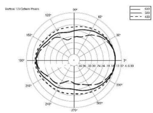
radar
Vertical 1/3 Octave Poles
| Angle | 630 | 500 | 400 |
|---|---|---|---|
| 0° | 18.19 | 18.19 | 18.19 |
| 30° | 18.19 | 18.19 | 18.19 |
| 60° | 18.19 | 18.19 | 18.19 |
| 90° | 18.19 | 18.19 | 18.19 |
| 120° | 18.19 | 18.19 | 18.19 |
| 150° | 18.19 | 18.19 | 18.19 |
| 180° | 18.19 | 18.19 | 18.19 |
| 210° | 18.19 | 18.19 | 18.19 |
| 240° | 18.19 | 18.19 | 18.19 |
| 270° | 18.19 | 18.19 | 18.19 |
| 300° | 18.19 | 18.19 | 18.19 |
| 330° | 18.19 | 18.19 | 18.19 |
| 360° | 18.19 | 18.19 | 18.19 |
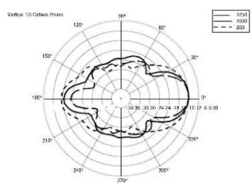
radar
Vertical 125 Octave Poles
| Angle | 1250 | 1000 | 800 |
|---|---|---|---|
| 0° | 19.12 | 18.19 | 17.46 |
| 30° | 19.12 | 18.19 | 17.46 |
| 60° | 19.12 | 18.19 | 17.46 |
| 90° | 19.12 | 18.19 | 17.46 |
| 120° | 19.12 | 18.19 | 17.46 |
| 150° | 19.12 | 18.19 | 17.46 |
| 180° | 19.12 | 18.19 | 17.46 |
| 210° | 19.12 | 18.19 | 17.46 |
| 240° | 19.12 | 18.19 | 17.46 |
| 270° | 19.12 | 18.19 | 17.46 |
| 300° | 19.12 | 18.19 | 17.46 |
| 330° | 19.12 | 18.19 | 17.46 |
The chart displays a polar coordinate system with angular positions (in degrees) on the x-axis and radial values (in degrees) on the y-axis. The legend indicates three distinct series: '1250', '1000', and '800'. The data points are plotted as connected lines forming a polygonal shape, suggesting a comparison of three discrete datasets or measurements across the angular range. No explicit numerical values are provided for the series.
radar
| Angle | Value |
|-------|-------|
| 0° | 10000 |
| 90° | 8000 |
| 60° | 6000 |
| 30° | 4000 |
| -30° | 2000 |
| -15° | 1000 |
| -12° | 500 |
| -6° | 300 |
| -3° | 100 |
| 0° | 50 |
| 30° | 30 |
| 60° | 10 |
| 90° | 5 |
| 120° | 3 |
| 150° | 1 |
| 180° | 5 |
| 210° | 3 |
| 240° | 1 |
| 270° | 5 |
| 300° | 3 |
| 330° | 1 |
| 360° | 5 |
radar
| Angle | Value |
|-------|-------|
| 0° | 1200 |
| 30° | 1500 |
| 60° | 1800 |
| 90° | 2100 |
| 120° | 2400 |
| 150° | 2700 |
| 180° | 3000 |
| 210° | 3300 |
| 240° | 3600 |
| 270° | 3900 |
| 300° | 4200 |
| 330° | 4500 |
| 360° | 4800 |

2 YEARS
WARRANTY CERTIFICATE
SERIAL NUMBER
Dear Customer, thank you for choosing this RCF product.
This warranty is valid for the following SERIAL NUMBER:
This hologram guarantees that your RCF product is ORIGINAL Please verify that the same hologram is applied on your product.
The RCF warranty is valid for a period of two (2) years from date of purchase printed on the receipt/invoice/bill in your possession.
Please keep this document together with the proof of purchase in a safe place.
You will need to produce the full documentation in order to take advantage of the guarantee.
Login or register on www.rcf.it/product-registration.
From the User Dashboard you can select the "Product Registration" tab and register your product using the serial number. Thanks to this procedure you will get an Extra Year Warranty for each product registered.

QUALITY REFERENCE No.

Verfall
WARRANTY TERMS AND CONDITIONS
The following terms and conditions apply to the Standard Warranty, which will be valid for a period of 24 (twenty-four) months that will automatically start on the delivery date of the product.
This Warranty does not alter or cancel out the consumer rights established by local laws or the rights provided for in any purchasing contracts drawn up with retailers. The Warranty for faults in RCF products is restricted solely to the services covered by this Warranty. The Consumer may have other rights, which vary from country to country. If the local legislation renders invalid, forbids or exceeds any of the clauses in this warranty, the remaining clauses will nonetheless remain valid.
Duration and conditions for the validity of the warranty
RCF SpA provides a warranty for any faults in this product that are present at the time of delivery and become evident within 24 months of the delivery date of the product. - Proof of the delivery date must be provided (by both the Purchaser and by the Third Party that subsequently bought the product, if any) by a delivery document issued by the Seller or another supporting document (such as a receipt), which gives the name of the Seller and the delivery date of the product. RCF reserves the right to refuse to provide the service included in the warranty if the abovementioned details are missing or have been deleted or altered after the initial purchase of the product.
- Any repair work done under the warranty must be carried out by staff at an authorised RCF Support Centre.
- The Consumer is responsible for providing suitable protection for the product using its original packaging. RCF SpA will not be held responsible for any damage that may occur during delivery as a result of unsuitable packaging.
- At no cost to the Consumer, RCF SpA will only repair faulty components or, at its discretion, replace a faulty product, or part of it, with another product that is identical or has an equivalent function. If RCF SpA is unable to repair or replace a faulty product, the purchase price paid will be refunded.
Any repairs or replacements of components or products will not result in the extension of the duration of this warranty, which will continue until the end of the 24-month period.
- Loss or damage to any software or data present in the product is not covered by the warranty. When repairing or replacing products, RCF will do all it can to reinstall the original software with any updates that it deems necessary in order for the product to operate correctly, but it will not save or reinstall any software or data in the faulty product that was not originally contained in it at the time of sale.
Exemption clauses
The RCF warranty will not be valid if the purchase document is illegible or if the serial number of the original RCF product has been deleted, altered or removed. Furthermore, this Standard Warranty from the manufacturer does not cover any work and/or repairs and/or spare parts that are found to be faulty due to:
- Failure to follow the installation, use and maintenance instructions given in the manual provided with the product
• Negligent or careless use
• Incorrect use and utilisation for purposes other than those for which the product was sold/designed
- Incorrect installation and/or connection to the power networks (electricity and data networks, etc.)
• Maintenance, repairs or modifications made by unauthorised personnel and/or failure to use genuine spare parts
- Damage resulting from transport or circumstances and/or events caused by force majeure (e.g. lightning, water, fire) that cannot be attributed to manufacturing faults in the product.
In addition, the warranty does not cover:
- Removable elements, knobs, light signals, and any accessories, consumption materials and parts that are subject to wear. They are only covered by the warranty when it can be demonstrated that they suffer from manufacturing faults.
- Technical work to install and connect the products, unless it is carried out by RCF.
Territorial coverage of the warranty
RCF SpA offers this warranty through its sales network. Therefore, Consumers must contact the Retailer with any requests for assistance. For further information about the support provided by RCF in each country, see our website www.rcf.it.
Limitations of responsibility
RCF SpA declines all responsibility for any damage that might arise directly or indirectly to people, things or animals as a result of failure to follow all of the steps described in the special User Instruction Manual, especially those regarding the installation, use and maintenance of the product.
Expiry of the warranty
After the end of the 24-month duration of this Manufacturer's Warranty, the Consumer will be charged for any repairs and/or replacements of components in accordance with the applicable rates of the Technical Support network authorised by the manufacturer.
CONDICIONES DE GARANTÍA
CONDITIONS DE GARANTIE
www.rcf.it/product-registration
From the User Dashboard you can
select the "Product Registration"
tab and register your product using
the serial number. Thanks to this
procedure you will get an Extra Year
Warranty for each product registered.
RCF S.p.a.
Via Raffaello Sanzio 13, 42124
Reggio Emilia (RE) - ITALY
Tel: +39 0522 274411
Fax: +39 0522 274484
www.rcf.it
GUIDE TO THE CORRECT PACKAGING DISPOSAL
Dear customer, our company is actively committed in environment protection and therefore encourages the correct disposal of all parts of the packaging that protect, accompany and promote its products, in order to allow separate disposal and reuse through new production cycles.
This guide summarizes the types of packaging materials used, and their final destination. Information reported is in addition to the marking applied on the aforementioned materials, introduced in compliance with EU decision 97/129/EC which establishes the obligations regarding environmental marking for the correct disposal of waste.
| COMPONENT | MATERIAL | SYMBOL | DISPOSAL (*) |
| CARTON BOX | Corrugated fibreboard |  | PAPER |
| WOOD BOX | Wood |  | RECYCLING AREA |
| INTERNAL PROTECTIONS | Corrugated fibreboard |  | PAPER |
| Paper |  | PAPER |
| Polyethylene terephthalate |  | PLASTIC |
| High density polyethylene |  | PLASTIC |
| Low density polyethylene |  | PLASTIC |
| Polystyrene |  | PLASTIC |
| Polyurethane |  | RECYCLING AREA |
| Wood |  | RECYCLING AREA |
| PLASTIC BAGS | Low density polyethylene |  | PLASTIC |
| PROMOTIONAL LABELS | Paper |  | PAPER |
(*) Always check local instruction regarding separate waste collection.

REGISTER AND RECEIVE AN EXTRA YEAR WARRANTY

FOR MORE DETAILS PLEASE
CHECK THE WARRANTY
CERTIFICATE