
W10509456 - Oven MAYTAG - Free user manual and instructions
Find the device manual for free W10509456 MAYTAG in PDF.
| Product Type | Oven |
| Brand | Maytag |
| Model | W10509456 |
| Fuel | Natural gas or propane (depending on configuration) |
| Main Functions | Baking, broiling, surface burners |
| Oven Capacity | 5 cu ft (142 L) |
| Cleaning Technology | AquaLift® (on some models) |
| Surface Burners | 4 to 6 burners depending on model; large, medium, small |
| Oven Burner | 1 bake burner |
| Broil Burner | 1 broil burner |
| Operating Altitude | Up to 5000 ft (1524 m) with conversion kit |
| Gas Supply Pressure | Natural gas: 5-14" WC; Propane: 11-14" WC |
| Burner Heat Output (sea level) | Surface burners: 5000 to 18000 BTU; Oven: 16500 to 18000 BTU; Broil: 10000 to 11000 BTU |
| Cleaning | Manual cleaning with mild detergent; avoid abrasive products |
| Safety | Gas leak detection recommended; manual shut-off valve; important safety instructions |
| Spare Parts | Orifices, injectors, regulator caps, screws |
| Repairability | Installation and conversion by a qualified professional |
| Required Tools | 1/2" and 5/8" combination wrenches, 7 mm nut driver, Quadrex/Phillips screwdriver, masking tape |
| Kit Contents W10509456 | Orifices and injectors for high altitude propane conversion, installation instructions |
Frequently Asked Questions - W10509456 MAYTAG
User questions about W10509456 MAYTAG
0 question about this device. Answer the ones you know or ask your own.
Ask a new question about this device
Download the instructions for your Oven in PDF format for free! Find your manual W10509456 - MAYTAG and take your electronic device back in hand. On this page are published all the documents necessary for the use of your device. W10509456 by MAYTAG.
USER MANUAL W10509456 MAYTAG
HIGH ALTITUDE KIT INSTALLATION INSTRUCTIONS
To convert single cavity freestanding ranges to elevations above 5000 ft (1524 m).
INSTRUCTIONS D'INSTALLATION POUR TROSSE D'UTILISATION EN HAUTE ALTITUDE
Two High Altitude Kits are available for select single cavity freestanding ranges. The choice depends on whether Natural gas or Liquefied Petroleum (LP) gas will be used. These instructions cover both gases and several range models with many different burners. Each kit contains orifices which will not be required for your range.
Kit Number W10509455 - Natural Gas (NG) High Altitude Kit for Single Oven Freestanding Ranges Contains:
2-Cooktop spud, Large burner NG high altitude
2-Cooktop spud, Medium-large burner NG high altitude
2-Cooktop spud, Medium burner NG high altitude
1 - Bake spud,NG AquaLift Technology Clean oven
1-Bake spud,NG 5.0 cu ft oven
1 - Broil hood, Female NG AquaLift® Technology Clean oven
1 - Broil hood, Male NG AquaLift ™ Technology Clean oven
1 - Broil hood, Female NG 5.0 cu ft oven
1 - Broil hood, Male NG 5.0 cu ft oven
Installation instructions
Kit Number W10509456 - Liquefied Petroleum (LP) Gas High Altitude Kit for Single Oven Freestanding Ranges Contains:
2-Cooktop spud, Large burner LP high altitude
2-Cooktop spud, Medium-large burner LP high altitude
2-Cooktop spud, Medium burner LP high altitude
1 - Cooktop spud, Small burner LP high altitude
1 - Bake spud, LP AquaLift Clean oven
1-Bake spud, LP 5.0 cu ft oven
1 - Broil hood, Female LP AquaLift® Technology Clean oven
1 - Broil hood, Male LP AquaLift Technology Clean oven
1 - Broil hood, Female LP 5.0 cu ft oven
1 - Broil hood, Male LP 5.0 cu ft oven
Installation instructions
Your safety and the safety of others are very important.
We have provided many important safety messages in this manual and on your appliance. Always read and obey all safety messages.
This is the safety alert symbol.
This symbol alerts you to potential hazards that can kill or hurt you and others.
All safety messages will follow the safety alert symbol and either the word "DANGER" or "WARNING."
These words mean:
DANGER
You can be killed or seriously injured if you don't immediately follow instructions.
WARNING
You can be killed or seriously injured if you don't follow instructions.
All safety messages will tell you what the potential hazard is, tell you how to reduce the chance of injury, and tell you what can happen if the instructions are not followed.
WARNING: If the information in this manual is not followed exactly, a fire or explosion may result causing property damage, personal injury or death.
- Do not store or use gasoline or other flammable vapors and liquids in the vicinity of this or any other appliance.
-
WHAT TO DO IF YOU SMELL GAS:
-
Do not try to light any appliance.
- Do not touch any electrical switch.
- Do not use any phone in your building.
- Immediately call your gas supplier from a neighbor's phone. Follow the gas supplier's instructions.
-
If you cannot reach your gas supplier, call the fire department.
-
Installation and service must be performed by a qualified installer, service agency or the gas supplier.
WARNING: Gas leaks cannot always be detected by smell.
Gas suppliers recommend that you use a gas detector approved by UL or CSA.
For more information, contact your gas supplier.
If a gas leak is detected, follow the "What to do if you smell gas" instructions.
In the State of Massachusetts, the following installation instructions apply:
■ Installations and repairs must be performed by a qualified or licensed contractor, plumber, or gasfitter qualified or licensed by the State of Massachusetts.
If using a ball valve, it shall be a T-handle type.
A flexible gas connector, when used, must not exceed 3 feet.
GAS CONVERSIONS
Tools Needed
Gather the required tools before starting installation. Read and follow the instructions provided with any tools listed here.
Tools needed
combination wrench
12" combination wrench
5% combination wrench
7 mm (%_32^ ) nut driver
Quadrex or Phillips screwdriver
■ Masking tape
Plastic bag for replaced parts
QUADREX is a registered trademark of NLW Holdings, Inc.
Gas Conversions
WARNING
Explosion Hazard
Use a new CSA International approved gas supply line. Install a shut-off valve.
Securely tighten all gas connections.
If connected to LP, have a qualified person make sure gas pressure does not exceed 14" (36 cm) water column.
Examples of a qualified person include: licensed heating personnel, authorized gas company personnel, and authorized service personnel.
Failure to do so can result in death, explosion, or fire.
WARNING
This conversion kit shall be installed by a qualified service agency in accordance with the manufacturer's instructions and all applicable codes and requirements of the authority having jurisdiction. If the information in these instructions is not followed exactly, a fire, explosion or production of carbon monoxide may result causing property damage, personal injury or loss of life. The qualified service agency is responsible for the proper installation of this kit. The installation is not proper and complete until the operation of the converted appliance is checked as specified in the manufacturer's instructions supplied with this kit.
IMPORTANT: Gas conversions must be done by a qualified installer. Before proceeding with the conversion, shut off the gas supply to the range prior to disconnecting the electrical power.
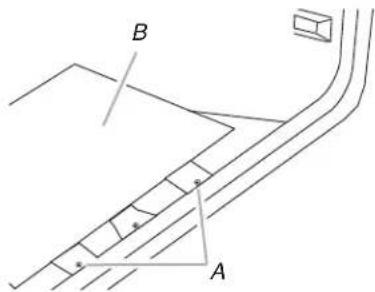
- Turn the manual shutoff valve to the closed position.
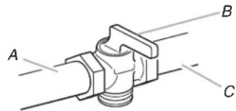
A. To range
B. Manual shutoff valve "closed" position
C. Gas supply line
- Unplug range or disconnect power.
Gas Pressure Regulator
The gas pressure regulator supplied with this range must be used. The inlet pressure to the regulator should be as follows for proper operation:
Natural gas:
Minimum pressure: 5^ WCP
Maximum pressure: 14" WCP
LP gas:
Minimum pressure: 11" WCP
Maximum pressure: 14" WCP
Contact local gas supplier if you are not sure about the inlet pressure.
Burner Input Requirements
Input ratings shown on the model/serial rating plate are for elevations up to 2,000 ft (609.6 m).
For elevations above 2,000 ft (609.6 m), ratings are reduced at a rate of 4% for each 1,000 ft (304.8 m) above sea level (not applicable for Canada).
Gas Supply Pressure Testing
Gas supply pressure for testing regulator must be at least 1" water column pressure above the manifold pressure shown on the model/serial rating plate.
Line pressure testing above 12 psi gauge (14" WCP)
The range and its individual shutoff valve must be disconnected from the gas supply piping system during any pressure testing of that system at test pressures in excess of 12 psi (3.5 kPa).
Line pressure testing at 12 psi gauge (14" WCP) or lower
The range must be isolated from the gas supply piping system by closing its individual manual shutoff valve during any pressure testing of the gas supply piping system at test pressures equal to or less than 1/2 psi (3.5 kPa).
To Convert Gas Pressure Regulator
NOTE: If the range will be using the same gas before and after conversion, it is not necessary to convert the gas pressure regulator. Ranges are set for Natural gas from the factory. If you are using Natural gas, no gas pressure regulator conversion is needed. Continue with "To Convert Surface Burners" in this section.
-
Remove storage drawer, warming drawer or premium storage drawer. See the "StorageDrawer" or "WarmingDrawer or Premium StorageDrawer" section in the Installation Instructions provided with the range.
-
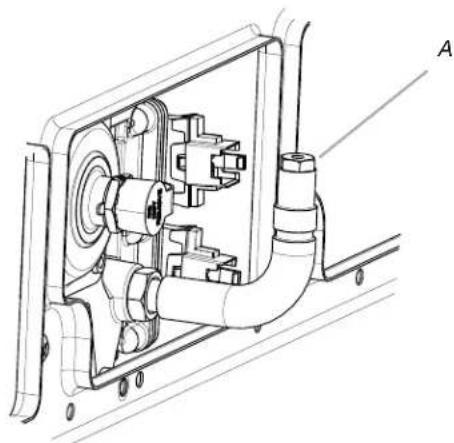
Locate gas pressure regulator at rear of storage or warming drawer compartment.
NOTE: On models with a warming drawer, an access cover must be removed to access the gas pressure regulator.
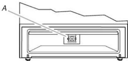
A. Gas pressure regulator
IMPORTANT: Do not remove the gas pressure regulator.
-
Remove plastic cover from gas pressure regulator cap.
-
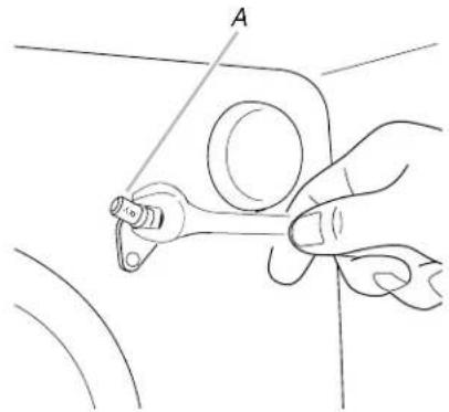
Turn gas pressure regulator cap counterclockwise with a 5 / 8 combination wrench to remove.
NOTE: Do not remove the spring beneath the cap.
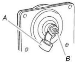
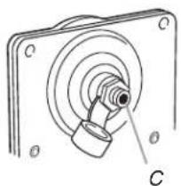
A. Plastic cover
B. Gas pressure regulator cap with solid end facing out
C. Gas pressure regulator cap with hollow end facing out
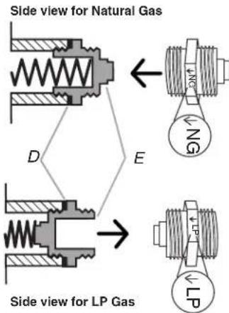
D.Washer
E. Gas pressure regulator cap
5. For Natural Gas:
Turn over the gas pressure regulator cap and reinstall on regulator so that the solid end faces out and the marking NG is facing the direction shown in the above drawing.
For LP gas:
Turn over the gas pressure regulator cap and reinstall on regulator so that the hollow end faces out and the marking LP is facing the direction shown in the above drawing.
- Replace plastic cover over gas pressure regulator cap.
To Convert Surface Burners
- Remove burner cap.
- Using a Phillips or Quadrex screwdriver, remove the burner base.
NOTE: Reinstall one of the screws through the range cooktop to hold the orifice spud holder in place while removing and replacing the orifice spuds.
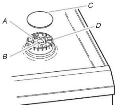
A. Igniter electrode
B. Gas tube opening
C.Burner cap
D. Burner base
- Apply masking tape to the end of a 7mm(%_32^*) nut driver to help hold the gas orifice spud in the nut driver while changing it. Press nut driver down onto the gas orifice spud and remove by turning it counterclockwise and lifting out. Set gas orifice spud aside.
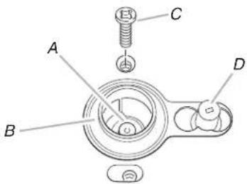
A. Orifice spud
C. Screw
B. Orifice spud holder
D. Spark electrode
- Locate the nameplate on the range. It will be located on the front frame behind the oven door or drawer front depending on model. Identify the burner ratings for this range from the nameplate.
Refer to the following chart for the gas to be used after the conversion. Identify the correct replacement orifice spuds using the nameplate burner ratings. The colors and ID number are marked on the hex flats of the orifice spuds.
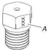
A. Hex flat
Natural Gas Orifice Spud Chart for Surface Burners
| Nameplate Burner Ratings (sea level) Natural Gas LP Color Size ID | Replacement Orifice - Natural gas (high altitude) Number | |
| 18,000 BTU 14,200 BTU Red/Orange | 1.90 mm N190 | |
| 17,000 BTU 14,200 BTU Red/Orange | 1.90 mm N190 | |
| 15,000/14,200 BTU Red/Orange | 1.90 mm N190 | |
| 13,000/11,000 BTU Yellow/Magenta | 1.70 mm N170 | |
| 12,000/11,000 BTU Yellow/Magenta | 1.70 mm N170 | |
| 9,500 BTU 8,000 BTU Red/White | 1.40 mm N140 | |
| 8,000 BTU 8,000 BTU Red/White* | 1.40 mm N140 | |
| 5,000 BTU 5,000 BTU Red/Brass* | 1.10 mm N110 | |
*Same orifices as shipped from factory for Natural gas.
LP Gas Orifice Spud Chart for Surface Burners
| Nameplate Burner Ratings (sea level) Natural Gas LP Color Size ID | Replacement Orifice - LP gas (high altitude) Number | |
| 18,000 BTU 14,200 BTU Yellow/ Brown | 0.99 mm L99 | |
| 17,000 BTU 14,200 BTU Yellow/ Brown | 0.99 mm L99 | |
| 15,000/ 15,500 BTU | 14,200 BTU Yellow/ Brown | 0.99 mm L99 |
| 13,000/ 13,500 BTU | 11,000 BTU Yellow/ Black | 0.88 mm L88 |
| 12,000/ 12,500 BTU | 11,000 BTU Yellow/ Black | 0.88 mm L88 |
| 9,500 BTU | 8,000 BTU | Yellow/ Green 0.84 mm L84 |
| 8,000 BTU | 8,000 BTU | Yellow/ Green 0.84 mm L84 |
| 5,000 BTU | 5,000 BTU | Yellow/ Silver 0.65 mm L65 |
NOTE: Refer to the Model Number and Serial Number Plate located on the oven frame behind the top left side of the oven door for proper sizing of spuds for each burner location.
- Save the replaced orifice spuds in a plastic bag or other container.
- Replace the burner base using both screws.
- Replace bumer cap.
- Repeat steps 1-7 for the remaining burners.
To Convert Oven Bake Burner
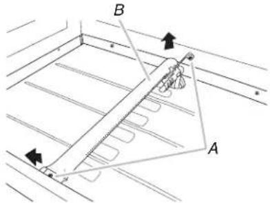
- Remove the oven racks.
- Remove 2 screws at the rear of the oven bottom.
- Lift the rear of the oven bottom up and back until the front of the panel is away from the front frame. Remove from oven and set it aside on a covered surface.
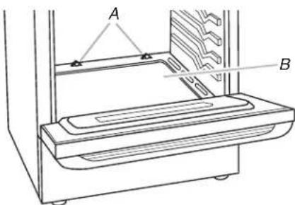
A. Screws
B.Oven bottom
- Remove 2 screws from the front tabs of the flame spreader. Lift front of the flame spreader and pull forward to remove tabs from rear of oven and set it aside on a covered surface. NOTE: On some models, the flame spreader will be attached to the oven bottom, and this step will not be necessary.
A. Screws
B. Flame spreader
- Remove 2 screws from the bake burner.
NOTE: Some models may have a single screw holding the bake burner in place.
- Slide the front of the bake burner to the side to remove tab from front of oven. Lift the back of the bake burner off the oven orifice, and set the bake burner aside.
A. Screws
B. Bake burner
- Refer to the nameplate on the range located on the front frame behind the oven door or drawer front depending on model. Identify the bake burner rating for this range from the nameplate. Refer to the following chart for the gas to be used after the conversion. Identify the correct replacement bake burner spud using the nameplate burner rating. The ID number is marked on the hex flats of the orifice spud.
Natural Gas Orifice Spud Chart for Bake Burners
| Nameplate Burner Ratings (sea level) | Replacement Orifice - Natural Gas (high altitude) |
| Natural Gas LP Size ID Number | |
| 18,000 BTU 17,000 BTU 1.78 mm 178 | |
| 16,500 BTU 15,500 BTU 1.70 mm 170 | |
| LP Gas Orifice Spud Chart for Bake Burners | |
| Nameplate Burner Ratings (sea level) | Replacement Orifice - LP Gas (high altitude) |
| Natural Gas LP Size ID Number | |
| 18,000 BTU 17,000 BTU 1.09 mm 57 | |
| 16,500 BTU 15,500 BTU 1.07 mm 107 | |
- Use a 3/8 nut driver or combination wrench and turn the bake burner orifice spud counterclockwise to remove. Save the replaced orifice spud in a plastic bag or other container.
- Install the replacement bake burner orifice spud, turning it clockwise until snug.
IMPORTANT: Do not overtighten.
A. Orifice spud
- Position the back of the bake burner over the oven orifice, and slide the tab on front of the bake burner into the front of the oven.
- Reattach the bake burner with 2 screws.
- If the flame spreader is part of the oven bottom, continue with Step 14. Otherwise, insert the tabs on the rear of the flame spreader into the rear of the oven.
- Reattach the front tabs of the flame spreader to the oven with 2 screws.
- Position the front of the oven bottom panel toward the front frame and lower the rear of the oven bottom panel into the oven.
- Reattach the oven bottom panel with 2 screws.
To Convert Oven Broil Burner
- Remove the screws from the broil burner. NOTE: Some models only have one screw and a locating pin. Do not remove the pin.
- Remove the broil burner from the broil burner orifice hood. NOTE: The broil burner will hang in the back of the oven while you are changing the orifice hood.
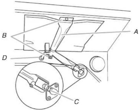
A. Broil burner
B. Screws
C. Orifice hood
D. Locating pin
- Use a 3/8 combination wrench and turn the broil burner orifice hood counterclockwise to remove. Save the replaced orifice hood in a plastic bag or other container.
NOTE: The broil fitting for the range may have a female or a male thread. This kit contains conversion broil fittings with the correct orifice size with both male and female threads.
- Refer to the nameplate on the range located on the front frame behind the oven door or drawer front depending on model. Identify the broil burner rating for this range from the nameplate. Refer to the following chart for the gas to be used after the conversion. Identify the correct replacement broil burner spud using the nameplate burner rating. The ID number is marked on the hex flats of the orifice spud.
Natural Gas Orifice Hood Chart for Broil Burners
| Nameplate Burner Ratings (sea level) Natural Gas LP Hood | Replacement Hood - Natural Gas (high altitude) | |
| Size ID | ||
| Thread | Number | |
| 11,000 BTU 11,000 BTU Female 1.40 mm 140 | ||
| 10,000 BTU 9,000 BTU Female 1.35 mm 135 | ||
| 11,000 BTU 11,000 BTU Male 1.40 mm 0.055 | ||
| 10,000 BTU 9,000 BTU Male 1.35 mm 135 | ||
LP Gas Orifice Hood Chart for Broil Burners
| Nameplate Burner Ratings (sea level) | Replacement Hood - LP Gas (high altitude) | |
| Natural Gas LP Hood | Size ID | |
| Thread | Number | |
| 11,000 BTU 11,000 BTU Female 0.90 mm 090 | ||
| 10,000 BTU 9,000 BTU Female 0.80 mm 080 | ||
| 11,000 BTU 11,000 BTU Male 0.90 mm 090 | ||
| 10,000 BTU 9,000 BTU Male 0.80 mm 080 | ||
- Install the replacement broiler burner orifice hood, turning it clockwise until snug.
IMPORTANT: Do not overtighten.
A. Orifice hood
- Place the broil burner on the broil burner orifice hood and insert the broil burner ceramic igniter in the hole in the rear of the oven.
- Position the broil burner against the top of the oven and reattach it.
- Replace storage drawer, warming drawer or premium storage drawer. See the "StorageDrawer" or "WarmingDrawer or Premium StorageDrawer" section in the Installation Instructions provided with the range.
- Replace the oven door if it has been removed. See the "Oven Door" section in the Installation Instructions provided with the range.
- Replace the oven racks.
Complete Installation
Refer to the Installation Instructions provided with the range for proper burner ignition, operation and burner flame adjustments.
IMPORTANT: You may have to adjust the "LO" setting for each cooktop burner.
Checking for proper cooktop, bake and broil burner flame is very important. The small inner cone should have a very distinct blue flame 14 (0.64 cm) to 12 (1.3 cm) long. The outer cone is not as distinct as the inner cone. LP gas flames have a slightly yellow tip.
NOTE: Make sure to save the orifices that have just been replaced in the conversion.
Notes
SECURITE POUR LA CONVERSION POUR CHANGEMENT DE GAZ

- HIGH ALTITUDE KIT INSTALLATION INSTRUCTIONS
- INSTRUCTIONS D'INSTALLATION POUR TROSSE D'UTILISATION EN HAUTE ALTITUDE
- Kit Number W10509455 - Natural Gas (NG) High Altitude Kit for Single Oven Freestanding Ranges Contains:
- Kit Number W10509456 - Liquefied Petroleum (LP) Gas High Altitude Kit for Single Oven Freestanding Ranges Contains:
- Your safety and the safety of others are very important.
- DANGER
- WARNING
- GAS CONVERSIONS
- Tools Needed
- Explosion Hazard
- Gas Pressure Regulator
- Natural gas:
- LP gas:
- Burner Input Requirements
- Gas Supply Pressure Testing
- Line pressure testing above 12 psi gauge (14" WCP)
- Line pressure testing at 12 psi gauge (14" WCP) or lower
- To Convert Gas Pressure Regulator
- For Natural Gas:
- For LP gas:
- To Convert Surface Burners
- To Convert Oven Bake Burner
- To Convert Oven Broil Burner
- Complete Installation
- SECURITE POUR LA CONVERSION POUR CHANGEMENT DE GAZ
Brand : MAYTAG
Model : W10509456
Category : Oven