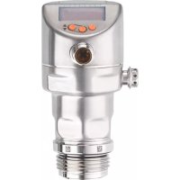
PI1789 - Pressure sensor IFM - Free user manual and instructions
Find the device manual for free PI1789 IFM in PDF.


User questions about PI1789 IFM
0 question about this device. Answer the ones you know or ask your own.
Ask a new question about this device
Download the instructions for your Pressure sensor in PDF format for free! Find your manual PI1789 - IFM and take your electronic device back in hand. On this page are published all the documents necessary for the use of your device. PI1789 by IFM.
USER MANUAL PI1789 IFM
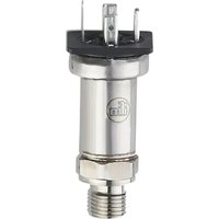
Operating instructions Electronic pressure sensor
PI17xx
Contents
1 Preliminary note 4
1.1 Symbols used 4
1.2 Warnings.... 4
2 Safety instructions.... 5
2.1 Cybersecurity 5
3 Intended use....7
3.1 Application area 7
4 Function 8
4.1 IO-Link 8
4.2 IO-Link properties of the sensor 9
4.2.1 Description IO-Link interface 9
4.2.2 Internal unit temperature 9
4.2.3 Counter overpressure events 9
4.2.4 Optical localisation 9
4.2.5 Event logging 9
4.2.6 Operating hours counter 9
4.2.7 Switching cycles counters 10
4.3 Analysis of the measuring cell.... 10
4.4 Defined state in case of a fault 10
4.5 Zero point behaviour of the device display and outputs.... 10
4.6 Operating modes 11
4.6.1 2-wire operation 11
4.6.2 3-wire operation 12
4.7 Switching function (only for 3-wire operation) 12
4.8 Analogue output 12
4.9 Customer-specific calibration 13
5 Installation Aseptoflex-Vario 15
5.1 Use in hygienic areas according to 3-A....16
5.2 Use in hygienic areas to EHEDG 16
5.3 Ventilation diaphragm 17
5.3.1 Function ventilation diaphragm 17
5.3.2 Orientation filter cover 17
5.3.3 Replace filter cover 17
6 Electrical connection.... 19
7 Operating and display elements 20
8 Menu....21
8.1 Menu structure: Main menu.... 21
8.2 Explanation of the main menu.... 21
8.3 Menu structure: Level 2 (extended functions) 22
8.4 Explanation of menu level 2 22
8.5 Menu structure: level 3 (simulation). 23
8.6 Explanation of menu level 3 23
9 Parameter setting 24
9.1 Parameter setting in general 24
9.2 Parameter setting via IO-Link 27
9.3 Configure display (optional).... 28
9.4 Set output signals 29
9.4.1 Setting of the output function.... 29
9.4.2 Set switching limits 29
9.4.3 Define switching limits for the window function 29
9.4.4 Scale analogue value for OUT2 29
9.5 User settings (optional) 30
9.5.1 Zero point calibration and adjustment of final value of the measuring range ..... 30
9.5.2 Define incorrect behaviour of the outputs 30
9.5.3 Set delay time for the switching outputs 30
9.5.4 Set output logic for the switching outputs 30
9.5.5 Set damping for the switching signal 30
9.5.6 Set damping for the analogue signal 31
9.6 Service functions.... 31
9.6.1 Read min/max values for the system pressure 31
9.6.2 Reset sensor / parameter 31
9.7 Simulation function 32
9.7.1 Open menu level 3 (simulation).... 32
9.8 Simulation.... 32
9.8.1 Set simulation value 32
9.8.2 Set simulation value 32
9.8.3 Switch simulation on / off. 32
9.8.4 Read overload processes 32
10 Operation 34
10.1 Read set parameters.... 34
10.2 Change the display in the Run mode 34
11 Troubleshooting 35
11.1 Troubleshooting 35
12 Disposal, repair and return 36
13 Factory setting 37
1 Preliminary note
You will find instructions, technical data, approvals and further information using the QR code on the unit / packaging or at documentation.ifm.com.
1.1 Symbols used
√ Requirement
Instructions
Reaction, result
[...] Designation of keys, buttons or indications
→ Cross-reference

Important note
Non-compliance may result in malfunction or interference.

Information
Supplementary note
1.2 Warnings
Warnings indicate the possibility of personal injury and damage to property. This enables safe product handling. Warnings are graded as follows:

WARNING
Warning of serious personal injury
▷ If the warning is not observed, fatal and serious injuries are possible.

CAUTION
Warning of minor to moderate personal injury
▷ If the warning is not observed, minor to moderate injuries are possible.
ATTENTION
Warning of damage to property
▷ If the warning is not observed, damage to property is possible.
2 Safety instructions
- The unit described is a subcomponent for integration into a system.
- The system architect is responsible for the safety of the system.
-
The system architect undertakes to perform a risk assessment and to create documentation in accordance with legal and normative requirements to be provided to the operator and user of the system. This documentation must contain all necessary information and safety instructions for the operator, the user and, if applicable, for any service personnel authorised by the architect of the system.
-
Read this document before setting up the product and keep it during the entire service life.
- The product must be suitable for the corresponding applications and environmental conditions without any restrictions.
- Only use the product for its intended purpose (→ Intended use).
- Only use the product for permissible media (→ Technical data).
- If the operating instructions or the technical data are not adhered to, personal injury and/or damage to property may occur.
- The manufacturer assumes no liability or warranty for any consequences caused by tampering with the product or incorrect use by the operator.
- Installation, electrical connection, set-up, operation and maintenance of the product must be carried out by qualified personnel authorised by the machine operator.
- Protect units and cables against damage.
• Store the device in its original packaging.

CAUTION
With high medium temperatures, parts of the device may heat up.
▷ Risk of burns
▶ Do not touch the device.
▶ Protect the housing against contact with flammable substances and unintentional contact.
ATTENTION
Applications where steam is applied
▷ Risk of mechanical damage of the sensor or the piping system due to steam surge.
▶ Protect the sensor from excessive stress due to cavitation and steam surge.
▶ Design the piping system according to the state of the art.
▶ Do not install the sensor in the direct vicinity of fittings, pipe bends and the like in order to prevent unnecessary maximisation of steam surges.
▶ Preheat the system before the steam enters and remove liquid residues from the pipes, e.g. by blowing out or other suitable measures.
▷ The permissible temperatures of the sensor must not be exceeded → Data sheet.
2.1 Cybersecurity
Installation
The device is suitable for operation in a secure environment according to IEC 62443-1-1.
The device was designed for operation behind a firewall.
▶ Carry out a risk assessment of the system according to IEC 62443-1-1.
▶ Take measures to ensure physical security.
Operation
▶ Observe the security functions described in the product documentation and the recommendations for their use.
Maintenance
- ▶ Back up system configuration and system data in accordance with your company’s change management processes.
Decommissioning
▶ Ensure that no sensitive information can fall into unauthorised hands.
▶ Always reset the system settings to the factory settings before decommissioning the device.
3 Intended use
The device measures and monitors the system pressure or the hydrostatic level and the temperature in systems.
3.1 Application area
Type of pressure: relative pressure
Information on pressure rating and bursting pressure → Data sheet
Avoid static and dynamic overpressure exceeding the indicated pressure rating by taking appropriate measures. The indicated bursting pressure must not be exceeded. Even if the bursting pressure is exceeded only for a short time, the unit may be destroyed. ATTENTION: Risk of injury!
Not suitable for systems that have to meet the criteria of E9.2 / 63-04 of the 3-A standard.
The device is vacuum resistant. Adhere to the specifications in the data sheet!
4 Function
Measuring cell:
- The system pressure is measured by a ceramic capacitive measuring system.
- The sealing of the ceramic measuring cell is free of elastomers and thus maintenance-free.
- The medium temperature is recorded on the back of the ceramic measuring cell: Accuracy calculation formula → Data sheet.
Signal transmission:
- The unit can be operated in SIO mode (standard input-output) or in IO-Link mode. The basic operation mode is SIO. When connected to an IO-Link master, the unit automatically switches to IO-Link mode. An additional manual switching is not required.
SIO-Mode:
- Analogue signal measured pressure value 4-20 mA (pin 2).
• Switching information (pin 4).
IO-Link mode:
• Measured pressure value
• Measured temperature value
- Exceeding and falling below the limits of the measuring range
- Device status
- Switching information
- Parameter setting
• Device diagnostics (events)
4.1 IO-Link
IO-Link is a communication system for connecting intelligent sensors and actuators to automation systems. IO-Link is standardised in the IEC 61131-9 standard.

General information on IO-Link at io-link.ifm

Input Output Device Description (IODD) with all parameters, process data and detailed descriptions of the device at documentation.ifm.com
IO-Link offers the following advantages:
• Interference-free transmission of all data and process values
• Parameter setting in the running process or presetting outside the application
- Parameters for identifying the connected devices in the system
• Additional parameters and diagnostic functions
• Automatic backup and restore of parameter sets in case of device replacement (data storage)
- Logging of parameter sets, process values and events
• Device description file (IODD - Input Output Device Description) for easy project planning
• Standardised electrical connection
- Remote maintenance
4.2 IO-Link properties of the sensor
4.2.1 Description IO-Link interface
A description of the IO-Link interface can be found at www.io-link.ifm
The sensor provides the internal unit temperature as a readable parameter for diagnostic purposes.
4.2.2 Internal unit temperature
The internal temperature of the sensor can be read via the IO-Link channel. Measuring range: -25...155°C (-13...311°F), resolution 1°C (1.8°F), precision +/- 5°C (9°F). Information on measuring range and accuracy → Data sheet.
4.2.3 Counter overpressure events
The unit has a counter for overpressure events. The value above which a pressure is considered to be overpressure can be set.
- HIPC = Counter overpressure events.
HIPC counts how often the limit HIPS has been exceeded.
The limit must be exceeded for at least 0.5 ms.
• HIPS = Threshold overpressure.
The [HIPC] can be reset with the reset command [Reset_HIPC] and the [Back-to-Box]. See: Reset sensor / parameter ( → ☐ 31)

In case of an interruption of the supply voltage, a maximum of the events of the last 10 minutes can be lost, as these are summed up in the background and have not yet been permanently transferred to the memory.
4.2.4 Optical localisation
The sensor can be localised in the plant via the commands [Blinken_An] / [Blinken_Aus]. When the command is used, the switching status LEDs flash and [IO-L] is displayed.
4.2.5 Event logging
With IO-Link, the sensor has two logging mechanisms:
• Event History (Parameter [Event_History])
• Event Counter (Parameter [Event_Counter])
The last 20 events that occurred are recorded in the event history. As long as no event has occurred, the value [noEvent] or [0] appears in this list.
The event counter (limited to 232 events) can be used to read how often a specific event has occurred at the sensor.
The event counter and the event history can be reset using the IO-Link commands [RESET_EVENT_HISTROY], [RESET_EVENT_COUTER] and [Back-to-Box].
See: Reset sensor / parameter ( → ☐ 31)
4.2.6 Operating hours counter
In the parameter [operating_hours], the hours are counted during which the sensor was active (cannot be reset).
4.2.7 Switching cycles counters
The sensor counts the switching cycles at output 1 and output 2 in the [OUT_Counter] parameter and stores this value every full 60 minutes.
A reset is possible with [Reset_to_zero] or the [Back to Box] reset.
See: Reset sensor / parameter ( → ☐ 31)
4.3 Analysis of the measuring cell
The ceramic capacitive measuring cell is a reliable and overloadable measuring system that requires no filling liquid.
The device permanently monitors its status and that of the measuring cell.
If the measuring cell is damaged, the analogue output switches to a defined state, adjustable via [FOU2], and this is also reported via the display on the device and the IO-Link interface.
Depending on the damage and the medium, the sensor will issue different messages:
- With conductive media such as water, the sensor will output [CELL Err] or another error message.
• In non-conductive media such as air or oil, the sensor will output [CELL Err].
A medium that penetrates very quickly can also cause the electronics to fail, thus preventing diagnostics.
The functionality of the measuring cell diagnostics [CELL Err] is deactivated ex works.
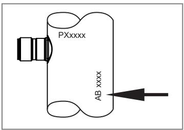

The parameter [cELd] can only be selected via IO-Link communication and is available from device status AB.
▶ For the device status see the labelling on the device. The position of the labelling varies depending on the device.
Fig. 1: Device status example:
Signalling on the sensor:
• [Cell] and [Err] are shown alternately in the display.
Output to the controller:
• The event [0x8CDF] is output. IO-Link ( → ☐ 8)

IO-Link masters interrupt communication with the device after a device fault.
▶ Event messages should therefore be saved.
4.4 Defined state in case of a fault
If a fault is detected, the analogue output passes into a defined state.

For error signalling (On = 21.5 mA, Off = 3.5 mA)
▶ Read parameters via IO-Link or contact the manufacturer
4.5 Zero point behaviour of the device display and outputs

Due to permissible device tolerances and temperature changes, the sensor can show a deviation from the zero point when no pressure is applied. To prevent this, the device is equipped with functions that keep the measured signal more stable at the process value 0.
Zero point behaviour of the device display and switching output:

Fig. 2: Device display and switching output
1: Process value
2: Sensor output signal with hysteresis (green)
3: Ideal measurement signal (red)
4: System pressure
5: Zero point stabilisation → Data sheet
The first process value that is shown on the device display and can be evaluated via the switching output is determined by the zero point stabilisation.
The switching output cannot be configured within the zero point stabilisation.

The zero point stabilisation is specified in \% of the span → Data sheet.
Zero point behaviour of the analogue output and communication via IO-Link:
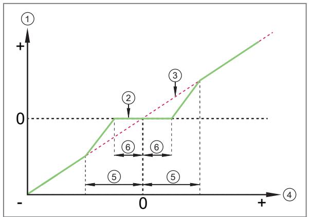
Fig. 3: Analogue output and communication via IO-Link
1: Process value
2: Sensor output signal (green)
3: Ideal measurement signal (red)
4: System pressure
5: Zero point stabilisation → Data sheet
6: 0.5 x zero point stabilisation → data sheet
The first process value that can be evaluated via the analogue output and the IO-Link communication is indicated by the half zero point stabilisation (6).
In the further range of the zero point stabilisation (5), the output signal of the sensor runs at a larger gradient angle.

The zero point stabilisation is specified in \% of the span → Data sheet.
4.6 Operating modes
The operating mode is defined by the wiring ( → Electrical connection) and automatically recognised by the unit.
4.6.1 2-wire operation
| OUT2 (pin 2) | Analogue signal proportional to pressure 4...20 mA or 20...4 mA |
4.6.2 3-wire operation
| OUT1 (pin 4) | 2 possibilities (automatic changeover)switching signal for pressure limit Communication via IO-Link |
| OUT2 (pin 2) | 3 possibilities (manual changeover in the menu)switching signal for pressure limit Analogue signal proportional to pressure 4...20 mAAnalogue signal proportional to pressure 20...4 mA |
4.7 Switching function (only for 3-wire operation)
OUTx changes its switching status if it is above or below the set switching limits (SPx, rPx). The following switching functions can be selected:
- Hysteresis function / normally open: [OUx] = [Hno] (→ Figure hysteresis function).
- Hysteresis function / normally closed: [OUx] = [Hnc] (→ Figure hysteresis function).
First the set point (SPx) is set, then the reset point (rPx) with the requested difference.
- Window function / normally open: [OUx] = [Fno] (→ Figure window function).
- Window function / normally closed: [OUx] = Fnc
- The width of the window can be set by means of the difference between SPx and rPx. SPx = upper value, rPx = lower value.

Fig. 4: Hysteresis function
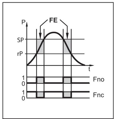
Fig. 5: Window function
| P = | System pressure |
| HY = | Hysteresis |
| FE = | Window |
4.8 Analogue output
The device provides an analogue signal proportional to the pressure. Within the measuring range the analogue signal is between 4...20 mA. The measuring range is scalable:
• [ASP2] defines at which measured value the output signal is 4 mA.
• [AEP2] defines at which measured value the output signal is 20 mA.

Minimum distance between [ASP2] and [AEP2] = 20 % of the final value of the measuring range.
If the measured value is outside the measuring range or in the event of an internal error, the current signal indicated in the following figure is provided. The analogue signal in case of an error is adjustable:
- [FOU] = On defines that the analogue signal goes to the maximum value (21.5 mA) in case of an error.
- [FOU] = Off defines that the analogue signal goes to the minimum value (3.5 mA) in case of an error.

Fig. 6: Output characteristics of the analogue output to Namur
| 1: | Analogue signal |
| 2: | Measured value (in configured unit) |
| 3: | Measuring range (factory setting) |
| 4: | Scaled measuring range |
| 5: | FOU = Off = 3.5 mA |
| 6: | FOU = On = 21.5 mA |
| P: | Pressure |
| MAW: | Initial value of the measuring range with non-scaled measuring range. |
| MEW: | Final value of the measuring range with non-scaled measuring range |
| ASP: | Analogue start point with scaled measuring range |
| AEP: | Analogue end point with scaled measuring range |
| UL: | Below the display range |
| OL: | Above the display range |
| FOU: | Output behaviour in case of an error |
4.9 Customer-specific calibration
The customer-specific calibration changes the curve of measured values compared to the real measured values (zero-point calibration and correction of gradient). Keep the following order:
▶ Carry out zero calibration [coF] in the range -5%....+5% of final value of the measuring range (VMR).
▶ Carry out calibration factor [CGA] in the range -5%....+5% of final value of the measuring range (VMR). The previous zero point calibration remains.
Example: Change zero point [coF]

A: Output signal
D: Pressure
MEW: Final value of the measuring range
V0: Curve of measured values at factory setting
V1, Changed curve of measured values
V2:
Example: Change in gradient [CGA]

A: Output signal
D: Pressure
MEW: Final value of the measuring range
V0: Curve of measured values at factory setting
V1, Changed curve of measured values
V2:
The change in the gradient is indicated in per cent.
▶ Enter analogue start [ASP] and [AEP] manually or via teach function.

If the gradient [CGA] and the offset [coF] are changed, the [ASP] and the [AEP] are influenced.
5 Installation Aseptoflex-Vario

CAUTION
If the medium temperature is above 50\ °C ( 122\ °F ), parts of the housing can increase in temperature to over 65\ °C ( 149\ °F ).
▷ Risk of burns.
▶ Protect the housing against contact with flammable substances and unintentional contact.
Before installing and removing the device: ▶ Make sure that no pressure is applied to the system and there is no medium in the pipe or tank.
▶ Note dangers related to machine / medium temperatures.
Information about available adapters at: www.ifm.com
▶ Observe the instructions of the adapter.
▶ Use a lubricating paste which is suitable and approved for the application.
▶ Insert the sensor with the process adapter into the process connection.
▶ Tighten it using a wrench: Tightening torque 35 Nm.
Further tightening may affect the sealing effect.
The process adapter can be adapted to different process connections.
Options are as follows:
1: Installation using a process adapter with sealing ring (hygiene-compliant to 3-A and EHEDG)
Article no. E332xx / E333xx.
▶ To meet the hygiene regulations use a process adapter with leakage port.
The adapters are supplied with EPDM O-ring (order no. E30054). More sealing rings are available as accessories:
• FKM O-ring (article no. E30123)
- PEEK sealing ring (order no. E30124). The PEEK sealing ring is long-term stable and maintenance-free.
▶ When you replace the PEEK sealing ring or change from a PEEK sealing ring to an O-ring, the process adapter also needs to be replaced with a new equivalent adapter.
2: Installation using a welding adapter with sealing ring (hygiene-compliant to 3-A and EHEDG)
▶ To meet the hygiene regulations use a process adapter with leakage port.
▶ Make sure that the process adapter does not warp during welding. Use welding mandrel E30452.
▶ The sealing edge must not be damaged by subsequent surface treatment. ( → Adapter operating instructions).
The adapter is supplied with EPDM O-ring (order no. E30054). Another sealing ring is available as accessory:
• FKM O-ring (order no. E30123);
3: Installation using a process adapter with hygienic metal-to-metal seal
Article no. E337xx / E338xx
A long-term stable, maintenance-free and gap-free fitting in the metal-to-metal sealing is only valid for once-only mounting.
▶ If the sealing has to be installed several times, use a new adapter.
4: Installation to G1 flange / G1 adapter
The sensor is sealed with the rear sealing ring at the process connection.
▶ The sealing area on the flange/adapter must be flush with the tapped hole and have a surface characteristic of min. Rz = 6.3 (observe DIN EN ISO 1179-1).
5.1 Use in hygienic areas according to 3-A

The following applies to devices with 3-A certification:
▶ Only use adapters with 3-A certification for the process connection.
▶ Do not install the device at the lowest point of the pipe or tank ( → position 5) in order that the medium can run off the area of the measuring element.
5.2 Use in hygienic areas to EHEDG
In case welded adapters are used, the food contact surface must be smooth (surface roughness Ra < 0.8 µ m) and the welding has to be done according to EHEDG Guideline 9 and 35.
The device is suited for CIP (cleaning in process) when installed correctly.
▶ Observe the application limits (temperature and material resistance) according to the data sheet.
▶ Ensure that the installation of the device in the system complies with EHEDG guidelines.
▶ Use self-draining installation.
▶ Only use process adapters permitted according to EHEDG with special seals required by the EHEDG position paper.
The gasket of the system interface must not be in contact with the sealing point of the sensor.
▶ When mounted in a tank, the installation must be flush mount. If not possible then direct water jet cleaning and cleaning of dead spaces must be possible.
▶ Leakage ports must be clearly visible and must be installed facing downwards for vertical pipes.

▶ To avoid dead space adhere to the dimensions: L < D
1: Leakage port
5.3 Ventilation diaphragm
5.3.1 Function ventilation diaphragm
▷ The ventilation diaphragm enables the relative pressure measurement since barometric and temperature-dependent pressure fluctuations between the measuring cell and the environment are compensated for.
The ventilation diaphragm is protected against damage by a screwed filter cover with circumferential ports.
For a correct functioning of the ventilation diaphragm please take the following into account:
▶ Remove soiling and cleaning agents immediately using plenty of lime-deficient splash water.
If the sensor is in a cooling stage:
▶ Avoid contact of the ventilation diaphragm with liquids to avoid negative pressure in the measuring system (resulting in a slightly falsified measured value) and additional strain on the diaphragm.
5.3.2 Orientation filter cover
Select the installation situation so that the filter cover is horizontal and the condensate can drain off due to gravity.
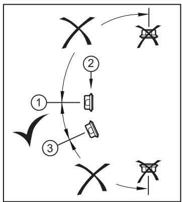
▶ Ideal orientation (1):
The filter cover is in a horizontal position.
The ventilation diaphragm (2) in the filter cover is in a vertical position.
▶ Maximum inclination of the filter cover: 30° (3)
5.3.3 Replace filter cover
| (1) Exchange of the filter cover incl. ventilation diaphragm (E30483). |
| In difficult environmental conditions or an installation situation that does not correspond to the ideal alignment (1), the following accessories can be used to protect the ventilation diaphragm: |
| (2) Replace the filter cover with a closed version (E30148)*. |
| (3) Replace the filter cover with a version with a tube fitting and a vent tube that ends in a protected and dry area (E30139). |
| (4) Set of accessories (E30467) with integrated replacement diaphragm (ventilation diaphragm). Recommended for chemically demanding applications in external cleaning. Function: (→ Installation instructions E30467). |
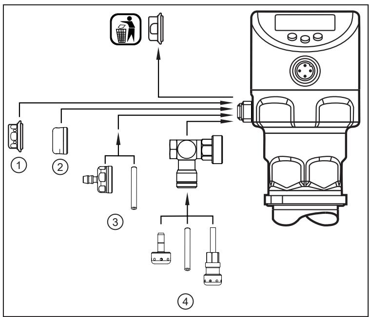

▶ Avoid soiling and moisture during the exchange.
▶ Clean the thread carefully and without residues.
▶ Do not damage the adhesive surface for the diaphragm on the sensor.
▶ Observe the orientation of the filter cover ( → Installation instructions E30139 / E30467).

*When using the closed filter cover, there is no more pressure compensation of the measuring cell. This results in measurement deviations caused by:
• Fluctuations of the atmospheric pressure.
- Fluctuations in the internal pressure of the unit with temperature changes.
6 Electrical connection

The unit must be connected by a qualified electrician.
Observe the national and international regulations for the installation of electrical equipment.
Voltage supply according to SELV, PELV.
▶ Disconnect power.
▶ Connect the unit as follows:
Connector: 1 x M12; : A


Fig. 7: Wiring diagram; MP: Multi-functional (OUT, Data)
2-wire
| Pin | Assignment |
| 1 | L+ |
| 2 | OUT2: AO |
3-wire
| Pin | Assignment |
| 1 | L+ |
| 2 | OUT2: DO2 (NO/NC), AO |
| 3 | L- |
| 4 | MP1: DO1 (NO/NC), IO-Link |
Parameter setting
| Pin | Assignment |
| 1 | L+ |
| 3 | L- |
| 4 | MP1: IO-Link |
7 Operating and display elements

| 1 to 8: Indicator LEDs | |
| LED 1 - 6 | Unit of measurement of the process value pressure (assignment is device-specific). |
| LED 7 | Switching status OUT2 (on if output 2 is switched). |
| LED 8 | Switching status OUT1 (on if output 1 is switched). |
| 9: (Enter) button | |
| Selection of the parameters and acknowledgement of the parameter values | |
| 10 to 11: Arrow keys up [▲] and down [▼] | |
| Setting of the parameter values (scrolling by holding pressed, incrementally by pressing once). Cancellation of input or return to menu: ▶ Press [▲] + [▼] simultaneously. | |
| 12: Alphanumeric display, 4 digits | |
| Display: Currently measured system pressure Display: Parameters and parameter values | |
8 Menu
8.1 Menu structure: Main menu
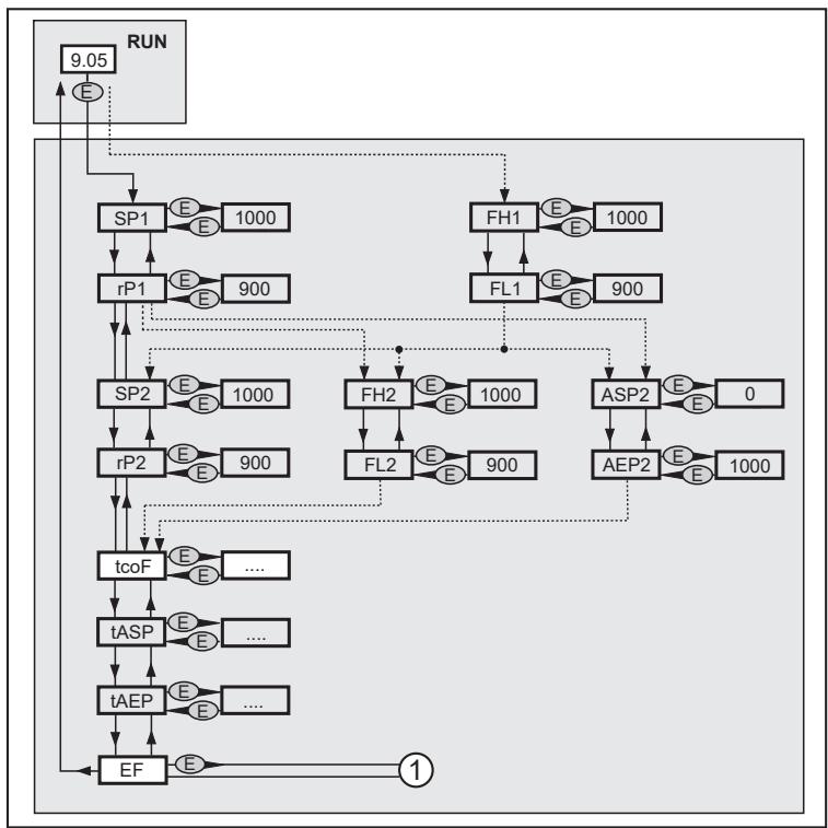
1: Change to menu level 2 (extended functions).

Menu items highlighted in grey are active depending on the configuration of the output.
8.2 Explanation of the main menu
| SPx / rPx* | Hysteresis function: upper / lower limit value for system pressure at which OUTx switches. Requirement: OUTx setting is [Hno] or [Hnc]. |
| FHx / FLx* | Window function: upper / lower limit value for system pressure at which OUTx switches. Requirement: OUTx setting is [Fno] or [Fnc]. |
| ASP2 | Analogue start point for system pressure: measured value at which 4 mA (20 mA) are provided. Requirement: OUT2 setting is [I] or ([InEG]). |
| AEP2 | Analogue end point for system pressure: measured value at which 20 mA (4 mA) are provided. Requirement: OUT2 setting is [I] or ([InEG]). |
| tcoF | Teach zero-point calibration. |
| tASP | Teach analogue start point for system pressure: set measured value at which 4 mA is provided (20 mA if [OU2] = [InEG]). |
| tAEP | Teach analogue end point for system pressure: set measured value at which 20 mA is provided (4 mA if [OU2] = [InEG]). |
| EF | Extended functions / opening of menu level 2. |
* menu items not active in 2-wire operation
8.3 Menu structure: Level 2 (extended functions)
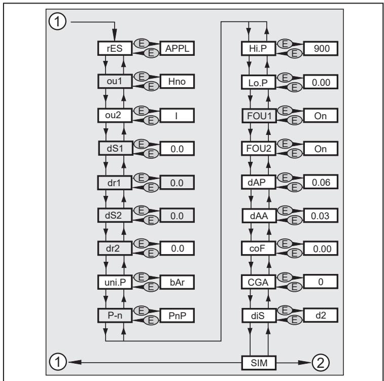
1: Change to the main menu, 2: Change to menu level 3 (simulation).

Menu items highlighted in grey are not active in 2-wire operation.
8.4 Explanation of menu level 2
| rES | Restore the factory settings. [APPL] = Application reset[btb] = Back to BoxSee: Reset sensor / parameter (→ 31) |
| ou1* | Output function for OUT1:Switching signal for the pressure limits: hysteresis function [H ..] or window function [F ..], either normally open [. no] or normally closed [. nc], output off [Off]. |
| ou2 | Output function for OUT2:Switching signal for the pressure limits: hysteresis function [H ..] or window function [F ..], either normally open [. no] or normally closed [. nc], output off [Off]. Analogue signal for the current system pressure: 4...20 mA [I]. |
| dS1 / dS2* | Switch-on delay for OUT1 / OUT2. |
| dr1 / dr2* | Switch-off delay for OUT1 / OUT2. |
| uni. P | Standard unit of measurement for system pressure (display):[bAr] / [mbar] / [MPA] / [kPA] / [PSI] / [inHG] / [iH2O] / [mmWS]. |
| P-n* | Output logic: pnp / npn. |
| Hi. P | Maximum value memory for system pressure. |
| Lo. P | Minimum value memory for system pressure. |
| FOU1* | Behaviour of output 1 in case of an internal fault. |
| FOU2 | Behaviour of output 2 in case of an internal fault. |
| dAP | Damping of the switch point / process data flow (IO-Link communication) and display (T63**). |
| dAA | Damping of the analogue output. Requirement: Setting OUT2 is [I] (T63**). |
| coF | Zero-point calibration between: -5%...+5% of VMR. |
| CGA | Adjustment of final value of the measuring range between: -5%...+5% of VMR. |
| diS | Update rate and orientation of the display |
| SIM | Open the submenu SIM (simulation) |
* menu items not active in 2-wire operation
** Time constant tau
8.5 Menu structure: level 3 (simulation)
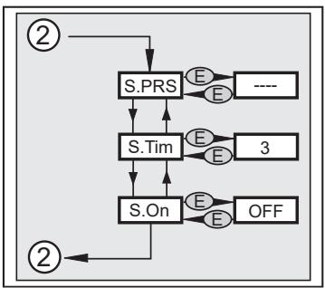
2: Change to menu level 2 (extended functions).
8.6 Explanation of menu level 3
| S. PRS | Simulation of a pressure / an error state |
| S. Tim | Simulation duration 1...60 min |
| S. On | Simulation start/stop |

The simulation is interrupted by pressing the [Enter] key.
9 Parameter setting
Parameter setting can be carried out via the IO-Link interface or via the operating elements on the unit.
Parameters can be set before installation or during operation.

If you change parameters during operation, this will influence the function of the plant.
▶ Ensure that there will be no malfunctions in your plant.
During parameter setting the unit remains in the operating mode. It continues to monitor with the existing parameter until the parameter setting has been completed.

Depending on the parameter setting, the parameters available in the menu may change.
9.1 Parameter setting in general

CAUTION
With high medium or ambient temperatures, parts of the housing may get hot.
▷ Risk of burns
▶ Do not touch the device with your hands.
▶ If necessary, use a blunt object to make settings on the device.
▶ 3 steps must be taken for each parameter setting:
1: Select parameter
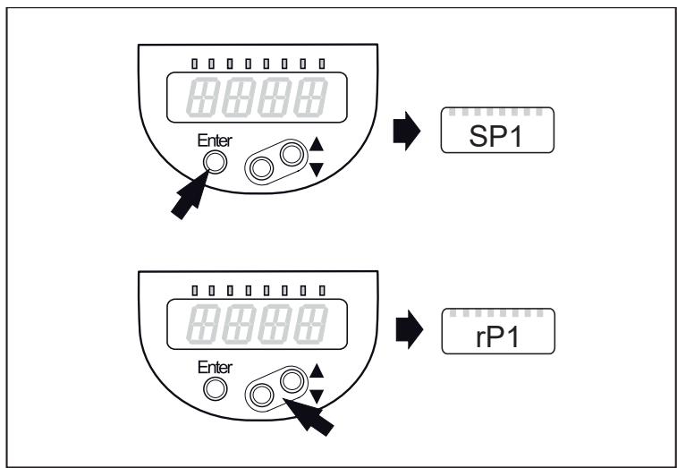
▶ Press [Enter] to get to the menu.
▶ Press [▲] or [▼] until the required parameter is displayed.
2: Set parameter value
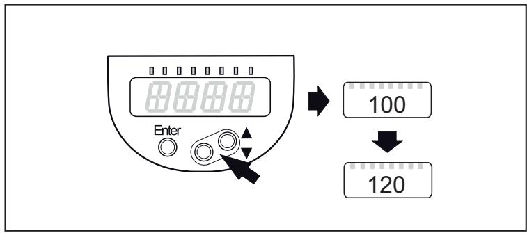
▶ Press [Enter] to edit the selected parameter.
▶ Press [▲] or [▼] for at least 1 s.
▷ After 1 s: setting value is changed:
Incrementally by pressing the button once or continuously by keeping the button pressed.
Numerical values are increased continuously with [▲] or decreased with [▼].
3: Acknowledge parameter value

▶ Briefly press [Enter].
▷ The parameter is displayed again. The new setting value is saved.
Set other parameters
▶ Press [▲] or [▼] until the required parameter is displayed.
Finish parameter setting
▶ Press [▲] or [▼] several times until the current measured value is displayed or wait for 30 s.
▷ The sensor returns to the process value display.
If [C. Loc] is displayed when an attempt is made to modify a parameter value, a parameter setting process is active via the IO-Link communication (temporary locking).
If [C. Loc] is displayed when an attempt is made to modify a parameter value, a parameter setting process is active via the IO-Link communication (temporary locking).
If [S. Loc] is displayed, the sensor is permanently locked via software. This locking can only be removed with a parameter setting software.
Change from menu level 1 to menu level 2:

▶ Press [Enter] to get to the menu.
▶ Press [▲] or [▼] until [EF] is displayed.
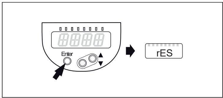
▶ Press [Enter].
▷ The first parameter of the submenu is displayed (here: [rES]).
▷ Continue with [▼].
Lock / unlock
The device can be locked electronically to prevent unintentional settings.
Locking

▶ Make sure that the device is in normal operating mode.
▶ Press [▲] + [▼] simultaneously for 10 s.
▷ [Loc] is displayed.
[Loc] is briefly displayed if you try to change parameter values.
Unlocking

▶ Press [▲] + [▼] simultaneously for 10 s.
▷ [uLoc] is displayed.
Timeout
If no button is pressed for 30 s during parameter setting, the unit returns to the operating mode with unchanged values.
Exit parameter without applying the settings:

▶ Press [▲] + [▼] simultaneously.
▷ Return to the menu level.
Exit menu level

▶ Press [▲] + [▼] simultaneously.
▷ Menu level 2 changes to level 1 or
level 1 changes to display.

In 2-wire mode, those menu items that refer to switching functions are not active ( → Menu structure); in addition, for some menu items, those parameter values that refer to switching functions cannot be selected.
9.2 Parameter setting via IO-Link
The device parameters can be set via the IO-Link interface in the following ways, for example:
- Parameter setting via a suitable parameter setting software, e.g. ifm moneo|configure
• Parameter setting via a PLC
• Parameter setting via an IIoT application
Requirements for parameter setting via the IO-Link interface:
√ The Input Output Device Description (IODD) for the device in case of parameter setting via a parameter setting software, see documentation.ifm.com
√ The IO-Link interface description (PDF) for the device in case of parameter setting via a PLC or IIoT application, see documentation.ifm.com
√ An IO-Link master
▶ Connect the IO-Link master to the parameter setting software, the PLC or the IIoT application.
▶ Connect the device to a suitable free port of the IO-Link master.
▶ Set the port of the IO-Link master to the IO-Link operating mode.
▷ The device changes to the IO-Link mode.
▶ Change the parameter settings in the software.
▶ Write the parameter settings to the device.

Support for system integration and parameter setting via IO-Link:
→ Manual of the parameter setting software (e.g. moneo)
→ Explanations and startup packages at ifm.com/cnt/io-link-system-integration.
9.3 Configure display (optional)

If the unit of measurement [uni. P] has to be changed, this needs to be done before setting other parameters to avoid internal rounding deviations due to unit conversion.
| ▶ Select [uni. P] and set the unit of measurement:• [bAr], [mbAr], [MPA], [kPA].• [psi] (depends on the device).• [InHO] (depends on the device).• [mWS] (depends on the device).• [mmWS] (depends on the device). | [uni. P] |

Selectable units of measurement → data sheet.
Uni. P only affects the sensor display. The IO-Link process value remains unaffected.
| ▶ Select [diS] and set the update rate and orientation of the display:• [d1]: update of the measured values every 50 ms.• [d2]: update of the measured values every 200 ms.• [d3]: update of the measured values every 600 ms.• [rd1], [rd2], [rd3]: display as with d1, d2, d3; rotated by 180°.• [OFF] = The measured value display is deactivated in the Run mode. When one of the buttons is pressed, the current measured value is displayed for 30 s. Pressing the [Enter] button again activates the display mode. The LEDs remain active even if the display is deactivated. Error messages are displayed even if the display is deactivated. | [diS] |
9.4 Set output signals
9.4.1 Setting of the output function
| ▶ Select [OU1] and set the switching function:• [Hno] = hysteresis function/normally open.• [Hnc] = hysteresis function/normally closed.• [Fno] = window function/normally open.• [Fnc] = window function/normally closed• [Off] = output off. | [OU1] |
| ▶ Select [OU2] and set the function:• [Hno] = hysteresis function/normally open.• [Hnc] = hysteresis function/normally closed.• [Fno] = window function/normally open.• [Fnc] = window function/normally closed• [I] = current signal proportional to pressure 4...20 mA.• [InEG] = current signal proportional to pressure 20...4 mA.• [Off] = output off. | [OU2] |
9.4.2 Set switching limits
| ▶ Select [SP1] / [SP2] and set the value at which the output switches. | [SP1][SP2] |
| ▶ Select [rP1] / [rP2] and set the value at which the output switches.rPx is always smaller than SPx. The unit only accepts values which are lower than the value for SPx. | [rP1][rP2] |
9.4.3 Define switching limits for the window function
| ▶ [ou1] /[ou2] must be set as [Fno] or [Fnc]. ▶ Select [FHx] and set the upper limit. | [FH1][FH2] |
| ▶ Select [FLx] and set the lower limit. FLx is always lower than FHx. The unit only accepts values which are lower than the value for FHx. | [FL1][FL2] |
9.4.4 Scale analogue value for OUT2
| ▸ ▶ Approach the desired minimum system pressure in the installation and keep it constant.▸ ▶ Select [tASP] with [Enter].▸ ▶ Press [▲] or [▼] until [----] is displayed.▸ ▶ Confirm [----] with [Enter].▸ ▷ The current pressure is defined as start value for the analogue signal. | [tASP] |
| ▸ ▶ Approach the desired maximum system pressure in the installation and keep it constant.▸ ▶ Select [tAEP] with [Enter].▸ ▶ Press [▲] or [▼] until [----] is displayed.▸ ▶ Confirm [----] with [Enter].▸ ▷ The current system pressure is defined as end value for the analogue signal. | [tAEP] |
ASP / AEP can only be set within defined limits ( → Setting ranges). If settings are made with an invalid pressure value, [Fail] and [UL] are displayed alternately for 30 s. The time can be cancelled by pressing a key, the ASP value / AEP value is not changed in this case.
| Alternatively:► ▶ Select [ASP] and set the measured value at which 4 mA is provided (20 mA if [OU2] = [InEG]).► ▶ Select [AEP] and set the measured value at which 20 mA is provided (4 mA if [OU2] = [InEG]). Minimum distance between ASP and AEP = 20 % of the final value of the measuring range (turn-down 1:5). | [ASP][AEP] |
9.5 User settings (optional)
9.5.1 Zero point calibration and adjustment of final value of the measuring range
| ► ▶ Select [coF] and set a value between -5%...+5%. The internal measured value "0" is shifted by this value. | [coF] |
| Alternatively: automatic adjustment of the offset in the range 0 bar ± 5%.► Make sure that no pressure is applied to the system.► ▶ Press [Enter] until [tCOF] appears.► ▶ Press [▲] or [▼] and keep it pressed. ▷ The current offset value (in %) flashes briefly. ▷ The current system pressure is displayed.► ▶ Release [▲] or [▼].► ▶ Briefly press [Enter] (= to confirm the new offset value). | [tcoF] |
| ► ▶ Select [CGA] and set a final value of the measuring range between -5% ...+5%. The internal final value of the measuring range “VMR” is shifted by this value. | [CGA] |
9.5.2 Define incorrect behaviour of the outputs
| ▶ Select [FOU1] and set the value:• [On] = output 1 switches ON in case of an error.• [OFF] = output 1 switches OFF in case of an error. ▶ Select [FOU2] and set the value:• [On] = output 2 switches ON in case of a fault, the analogue signal goes to the upper final value.• [OFF] = output 2 switches OFF in case of a fault, the analogue signal goes to the lower final value. | [FOU1][FOU2] |
9.5.3 Set delay time for the switching outputs
| [dS1] / [dS2] = switch-on delay for OUT1 / OUT2. | [dS1] |
| [dr1] / [dr2] = switch-off delay for OUT1 / OUT2. | [dr1] |
| ► ▶ Select [dS1], [dS2], [dr1] or [dr2] and set a value between 0.1 and 50 s (at 0.0 the delay time is not active). | [dS2] |
| [dr2] |
9.5.4 Set output logic for the switching outputs
| ▶ Select [P-n] and set [PnP] or [nPn]. | [P-n] |
9.5.5 Set damping for the switching signal
| ▶ Select [dAP] and set a value between 0.00...99.99 s; (at 0.00 [dAP] is not active).dAP value = response time between pressure change and change of the switching status in seconds. [dAP] influences the switching frequency: fmax = 1 ÷ 2dAP . [dAP] also has an effect on the display (T63*). | [dAP] |
* Time constant tau
9.5.6 Set damping for the analogue signal
| ▶ Select [dAA] and set a value between 0.01...99.99 s; (at 0.00 [dAA] is not active).dAA value = response time between pressure change and change of the analogue signal in seconds (T63*). | [dAA] |
* Time constant tau
9.6 Service functions
9.6.1 Read min/max values for the system pressure
| ▶ Select [Hi. P] or [Lo. P] and press [▲] or [▼] briefly. [Hi. P] = maximum value, [Lo. P] = minimum value. Delete memory:▶ Select [Hi. P] or [Lo. P]. ▶ Press [▲] or [▼] and keep pressed until [----] is displayed. ▶ Briefly press [Enter]. | [Hi. P][Lo. P] |
9.6.2 Reset sensor / parameter
If [rES] is to be exited without execution, carry out one of the following options:
▶ wait for 30 seconds.
▶ press [▲] and [▼] simultaneously.
▶ Disconnect the voltage supply
| ▶ Note the sensor settings before performing [rES]. ▶ Select [rES] and press [Enter]. ▶ Press [▲] or [▼]. ▶ Delay function = display flashes. ▶ After the delay function, select between [APPL] and [btb] with [▲] or [▼].• [APPL] = Application reset• [btb] = Back to Box▶ Press [Enter]. ▷ [----] The reset is executed. | [rES] |
| Application Reset [APPL]:• The application reset resets all sensor and output-related parameters. | [APPL] |
If IO-Link data storage is activated, this immediately triggers a parameter update in the master.
| Back to Box [btb]:• The Back to Box reset also resets all writable device identification parameters such as the Application SpecificTag | [btb] |
After the reset, the sensor suspends communication and measurement operation until the voltage is interrupted. The IO-Link data storage is not triggered.
9.7 Simulation function
9.7.1 Open menu level 3 (simulation)
| ▶ Select the parameter [SIM] in menu level 2 (extended functions) with [▲] or [▼]. ▶ Press [Enter] (= open menu level 3). ▷ Simulation parameters are selectable. | [SIM] |
9.8 Simulation
9.8.1 Set simulation value
| ▶ Select [S. PRS]. ▶ Set the process value to be simulated:[Numerical value] = pressure (depending on basic setting). [OL] = Above the measuring range. [UL] = Below the measuring range. [Err] = Electronic error detected. [CELL] = Cell diagnostics event▶ Press [Enter]. | [S. PRS] |
9.8.2 Set simulation value
| ▶ Select [S. Tim]. ▶ Set time span for simulation. ▶ Press [Enter]. Setting range: 1, 2, 3, 4, 5, 10, 15, 20, 30, 45, 60 min. Factory setting: 3 min. | [S. Tim] |
9.8.3 Switch simulation on / off
| ▶ Select [S. On] and set:[OFF] = simulation off[On] = simulation on▶ Press [Enter] to start the simulation | [S. On] |

Simulation active until [Enter] is pressed again or the time set via [STim] elapses. During the simulation [SIM] is displayed every 3 s.
After the simulation the unit returns to the parameter [S. On] and internally the unit returns to the operating mode (and the process value transmission). After another 30 s the display returns to the process value display.

If the simulation is started via IO-Link, it can also only be finished via IO-Link. During the attempt to finish the simulation via the buttons, C. Loc is displayed.
9.8.4 Read overload processes
| HIPC: Number of overload processes. HIPC counts how often the limit HIPS has been exceeded. The limit must be exceeded for at least 0.5 ms. HIPS: Setting of the threshold for the overload counter. | [HIPC][HIPS] |

The parameters HIPC and HIPS are only available via IO-Link communication.

In case of an interruption of the supply voltage, a maximum of the events of the last 10 minutes can be lost, as these are summed up in the background and have not yet been permanently transferred to the memory.
10 Operation
After power-on and expiry of the power-on delay time of approx. 0.5 s the unit is in the RUN mode (= normal operating mode). It carries out its measurement and evaluation functions and generates output signals according to the set parameters.
10.1 Read set parameters
▶ Press [Enter].
▶ Press [▲] or [▼] until the required parameter is displayed.
▶ Briefly press [Enter].
▷ The unit displays the corresponding parameter value for approx. 30 s; then it changes to the process value display.

Alternative to the 30 s waiting time:
▶ Cancellation of display: Press [▲] + [▼] simultaneously.
▷ The waiting time of 30 s is omitted.
10.2 Change the display in the Run mode
Activation of the display when the display is in OFF mode:
▶ Briefly press [Enter].
▷ The unit displays the current measured value in the selected type of display for approx. 30 s:
11 Troubleshooting
11.1 Troubleshooting
The device has many self-diagnostic options.
• It monitors itself automatically during operation.
- It indicates warnings and faults via IO-Link and via display (even if the display is deactivated).
- If a fault is found, the outputs are set according to the setting of the parameters [FOU1] and [FOU2].
| Indication | Warning | Error | Status LED | Type of error or event | Corrective measures |
| Err | X | unit faulty | ► Replace the device. | ||
| CELL + Err (alternately) | X | measuring cell defective | ► Replace the device. | ||
| SIM + PW (alternately) | X | Simulation function active | |||
| IO-L | X | Optical identification function active | |||
| OFF | X | Supply voltage too low. | ► Check / correct the supply voltage. ► ▶ In 2-wire operation: Check / correct the connected load. | ||
| SC1 | X | OUT1 flashes | Short circuit switching output 1. | ► Check switching output 1 for short circuit, eliminate fault. | |
| SC2 | X | OUT2 flashes | Short circuit switching output 2. | ► Check switching output 2 for short circuit, eliminate fault. | |
| SC | X | OUT1 and OUT2 flash | Short circuit switching output 1 and switching output 2. | ► Check switching outputs 1 and 2 for short circuits; Remove the fault. | |
| PArA | X | Parameter setting outside the permissible range. | ► Repeat parameter setting. ► Change parameter setting ► ▶ Carry out [APPL] or [btb] reset. See: Reset sensor / parameter (→ 31) | ||
| OL | X | Above the measuring range: measured value greater +5% MEW | ► Check / reduce pressure. | ||
| UL | X | Below the measuring range: | ► Check / increase pressure. | ||
| Loc | X | Setting keys on the device locked, parameter change rejected. | ► Unlock. | ||
| C. Loc | X | Parameter setting via keys locked, parameter setting is active via IO-Link communication. | ► Finish the IO-Link communication before parameters are set on the sensor. | ||
| S. Loc | X | Setting keys locked via parameter setting software, parameter change rejected. | ► Unlock sensor via parameter setting software. |
12 Disposal, repair and return
▶ After use dispose of the unit in an environmentally friendly way in accordance with the applicable national regulations.
▶ In case of return shipment, ensure that the unit is free from soiling, especially from dangerous and toxic substances.
▶ It is not possible to repair the unit.
13 Factory setting
| Factory setting | User settings | |
| cELd | off | |
| SP1 | 25% MEW* | |
| rP1 | 23% MEW* | |
| OU1 | Hno | |
| OU2 | I | |
| SP2 | 75% MEW* | |
| rP2 | 73% MEW* | |
| coF / tcoF | 0.0 | |
| ASP / tASP | 0% MEW*PI1x09: -1 bar | |
| AEP / tAEP | 100% MEW* | |
| dS1 | 0.0 | |
| dr1 | 0.0 | |
| dS2 | 0.0 | |
| dr2 | 0.0 | |
| Uni | bAr / mbAr | |
| FOU1 | on | |
| FOU2 | on | |
| P-n | pnp | |
| dAP | 0.06 / 2.00** | |
| dAA | 0.06 / 2.00** | |
| dis | d2 |
* = The indicated percentage of the final value of the measuring range (MEW) of the respective sensor (for PI1709 the percentage of the measuring span) is set.
** = Devices up to 4 bar nominal pressure dAP = 2 / Devices over 4 bar nominal pressure dAP = 0.06
- 1 PRELIMINARY NOTE
- 1.1 SYMBOLS USED
- 1.2 WARNINGS
- 2 SAFETY INSTRUCTIONS
- 2.1 CYBERSECURITY
- 3 INTENDED USE
- 3.1 APPLICATION AREA
- 4 FUNCTION
- 4.1 IO-LINK
- 4.2 IO-LINK PROPERTIES OF THE SENSOR
- 4.2.1 DESCRIPTION IO-LINK INTERFACE
- 4.2.2 INTERNAL UNIT TEMPERATURE
- 4.2.3 COUNTER OVERPRESSURE EVENTS
- 4.2.4 OPTICAL LOCALISATION
- 4.2.5 EVENT LOGGING
- 4.2.6 OPERATING HOURS COUNTER
- 4.2.7 SWITCHING CYCLES COUNTERS
- 4.3 ANALYSIS OF THE MEASURING CELL
- 4.4 DEFINED STATE IN CASE OF A FAULT
- 4.5 ZERO POINT BEHAVIOUR OF THE DEVICE DISPLAY AND OUTPUTS
- 4.6 OPERATING MODES
- 4.6.1 2-WIRE OPERATION
- 4.6.2 3-WIRE OPERATION
- 4.7 SWITCHING FUNCTION (ONLY FOR 3-WIRE OPERATION)
- 4.8 ANALOGUE OUTPUT
- 4.9 CUSTOMER-SPECIFIC CALIBRATION
- 5 INSTALLATION ASEPTOFLEX-VARIO
- 5.1 USE IN HYGIENIC AREAS ACCORDING TO 3-A
- 5.2 USE IN HYGIENIC AREAS TO EHEDG
- 5.3 VENTILATION DIAPHRAGM
- 5.3.1 FUNCTION VENTILATION DIAPHRAGM
- 5.3.2 ORIENTATION FILTER COVER
- 5.3.3 REPLACE FILTER COVER
- 6 ELECTRICAL CONNECTION
- 7 OPERATING AND DISPLAY ELEMENTS
- 8 MENU
- 8.1 MENU STRUCTURE: MAIN MENU
- 8.2 EXPLANATION OF THE MAIN MENU
- 8.3 MENU STRUCTURE: LEVEL 2 (EXTENDED FUNCTIONS)
- 8.4 EXPLANATION OF MENU LEVEL 2
- 8.5 MENU STRUCTURE: LEVEL 3 (SIMULATION)
- 8.6 EXPLANATION OF MENU LEVEL 3
- 9 PARAMETER SETTING
- 9.1 PARAMETER SETTING IN GENERAL
- 9.2 PARAMETER SETTING VIA IO-LINK
- 9.3 CONFIGURE DISPLAY (OPTIONAL)
- 9.4 SET OUTPUT SIGNALS
- 9.4.1 SETTING OF THE OUTPUT FUNCTION
- 9.4.2 SET SWITCHING LIMITS
- 9.4.3 DEFINE SWITCHING LIMITS FOR THE WINDOW FUNCTION
- 9.4.4 SCALE ANALOGUE VALUE FOR OUT2
- 9.5 USER SETTINGS (OPTIONAL)
- 9.5.1 ZERO POINT CALIBRATION AND ADJUSTMENT OF FINAL VALUE OF THE MEASURING RANGE
- 9.5.2 DEFINE INCORRECT BEHAVIOUR OF THE OUTPUTS
- 9.5.3 SET DELAY TIME FOR THE SWITCHING OUTPUTS
- 9.5.4 SET OUTPUT LOGIC FOR THE SWITCHING OUTPUTS
- 9.5.5 SET DAMPING FOR THE SWITCHING SIGNAL
- 9.5.6 SET DAMPING FOR THE ANALOGUE SIGNAL
- 9.6 SERVICE FUNCTIONS
- 9.6.1 READ MIN/MAX VALUES FOR THE SYSTEM PRESSURE
- 9.6.2 RESET SENSOR / PARAMETER
- 9.7 SIMULATION FUNCTION
- 9.7.1 OPEN MENU LEVEL 3 (SIMULATION)
- 9.8 SIMULATION
- 9.8.1 SET SIMULATION VALUE
- 9.8.2 SET SIMULATION VALUE
- 9.8.3 SWITCH SIMULATION ON / OFF
- 9.8.4 READ OVERLOAD PROCESSES
- 10 OPERATION
- 10.1 READ SET PARAMETERS
- 10.2 CHANGE THE DISPLAY IN THE RUN MODE
- 11 TROUBLESHOOTING
- 11.1 TROUBLESHOOTING
- 12 DISPOSAL, REPAIR AND RETURN
- 13 FACTORY SETTING
Brand : IFM
Model : PI1789
Category : Pressure sensor