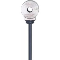
VSA005 - Accelerometer IFM - Free user manual and instructions
Find the device manual for free VSA005 IFM in PDF.


User questions about VSA005 IFM
0 question about this device. Answer the ones you know or ask your own.
Ask a new question about this device
Download the instructions for your Accelerometer in PDF format for free! Find your manual VSA005 - IFM and take your electronic device back in hand. On this page are published all the documents necessary for the use of your device. VSA005 by IFM.
USER MANUAL VSA005 IFM
Operating instructions
Acceleration sensors
VSAxxx
VSMxxx
VSPxxx
Contents
1 Preliminary note.... 3
1.1 Symbols used.... 3
1.2 Warnings.... 3
2 Safety instructions 4
3 Transport, handling and storage 5
4 Intended use 6
5 Function 7
5.1 Measuring principles / interfaces 7
5.2 Axis orientation.... 7
5.3 Self-test.... 7
6 Installation.... 9
6.1 Prepare contact surface 9
6.2 Types of mounting.... 9
6.2.1 Screw 9
6.2.2 Glue 9
6.2.3 Magnet 10
6.2.4 Fixing a sensor with a 90° cone 10
7 Electrical connection 11
7.1 MEMS sensors with current output (VSA) 11
7.2 MEMS sensors with IEPE output (VSM) 11
7.3 Piezo sensors with IEPE output (VSP) 12
7.4 Connection to the VSE diagnostic electronics.... 12
7.5 Use of screened cables 12
7.5.1 VSA / VSP devices 12
7.5.2 VSM devices 13
7.6 Connection examples.... 13
8 Maintenance, repair and disposal 15
1 Preliminary note
You will find instructions, technical data, approvals, accessories and further information using the QR code on the device / packaging or at documentation.ifm.com.
1.1 Symbols used
√ Requirement
Instruction
Reaction, result
bold Designation of keys, buttons or indications
→ Cross-reference without link
→ Cross-reference with link

Important note
Non-compliance may result in malfunction or interference

Information
Supplementary note
1.2 Warnings
Warnings indicate the possibility of personal injury and damage to property. This enables safe product handling. Warnings are graded as follows:

WARNING
Warning of serious personal injury
▷ If the warning is not observed, fatal and serious injuries are possible.

CAUTION
Warning of minor to moderate personal injury
▷ If the warning is not observed, minor to moderate injuries are possible.

ATTENTION
Warning of damage to property
▷ If the warning is not observed, damage to property is possible.
2 Safety instructions
- The unit described is a subcomponent for integration into a system.
- The system architect is responsible for the safety of the system.
-
The system architect undertakes to perform a risk assessment and to create documentation in accordance with legal and normative requirements to be provided to the operator and user of the system. This documentation must contain all necessary information and safety instructions for the operator, the user and, if applicable, for any service personnel authorised by the architect of the system.
-
Read this document before setting up the product and keep it during the entire service life.
- The product must be suitable for the corresponding applications and environmental conditions without any restrictions.
- Only use the product for its intended purpose (→ Intended use).
- If the operating instructions or the technical data are not adhered to, personal injury and/or damage to property may occur.
- The manufacturer assumes no liability or warranty for any consequences caused by tampering with the product or incorrect use by the operator.
- Installation, electrical connection, set-up, operation and maintenance of the product must be carried out by qualified personnel authorised by the machine operator.
- Protect units and cables against damage.
3 Transport, handling and storage
▶ Store the device in its original packaging.
▶ When the device is to be stored again, use the original packaging.
▶ Otherwise, provide unused connections with either a mating connector or a protective cap and pack the device in suitable packaging.
▶ Observe the permissible ambient conditions for the device during storage (→ Technical data).
4 Intended use
The device is designed for vibration detection on machines and systems and for measuring the acoustic emission (acceleration).
• For connection to diagnostic electronics (e.g. VSE)
The following applies to VSPxxx devices when used in the USA and Canada:
For USA and Canada, this product is specified for the control of a production process in a dedicated building or factory (industrial area).
5 Function
Acceleration sensors measure the acoustic emission (acceleration) on non-rotating surfaces. The output signal of the sensor is the unfiltered raw signal of the acceleration within the scope of the specifications indicated in the data sheet.
5.1 Measuring principles / interfaces
- MEMS sensors (Micro-Electro-Mechanical Systems) are based on a capacitive measuring principle.
- Piezo sensors use the piezo-electric effect.
| Device family | Measuring principle* | Interface |
| VSA | MEMS | analogue current output |
| VSP | Piezo | IEPE(Integrated Electronics Piezo Electric), analogue voltage signal with constant supply current |
| VSM | MEMS |
* Recommendation: use MEMS based sensors when measuring accelerations of moving objects.
5.2 Axis orientation
For all one-axis sensors, the z axis is the measuring direction. The z axis corresponds to the screwing direction.

1: Installation direction
5.3 Self-test
Together with ifm's diagnostic units (VSE), MEMS sensors offer the possibility to carry out a self-test.
The sensor's measuring cell is artificially excited. The response to this excitation is measured and evaluated via the measuring line. The function of the entire measuring chain, including the measuring cell, is actively monitored.
In the case of piezo sensors that are connected to a suitable evaluation unit (e.g. VSE diagnostic electronics), an operating point (constant current) is reached to allow wire break monitoring. Testing the measuring cell is not possible.
With VSM sensors, the self-test of the measuring cell is only carried out via the z axis.
▶ Connect the corresponding cables (z axis and self-test line) to the same terminal of a suitable evaluation unit (e.g. VSExxx).
▷ The self-test is carried out correctly.
6 Installation
The measuring direction should be in the direction of the main vibration. The main vibration is usually in radial direction to the shaft.
In case of fixed bearings with high axial force absorption or axial bearings, the recommended measuring direction is axial to the shaft.
▶ Mount only in a thick housing wall and vertically to the machine surface close to the bearing or at the end shield.
▶ Note the measuring direction of the sensor.
▶ Ensure a safe vibration transmission and allow no elastic intermediate layers.
Adapters of any kind have an impact on the vibration measurement. The mass, shape and stiffness of the adapter have an influence on the frequency response of the entire system. Both resonances and damping effects may occur in different frequency ranges.
▶ For all installation types, tighten the sensor with the tightening torque indicated in the data sheet.

▷ A tightening torque that is too low may lead to insufficient coupling between the sensor and the machine whereas a tightening torque that is too high may damage the sensor and the screw.
6.1 Prepare contact surface
▶ Prepare a clean and smooth contact surface that is free from any coating to fix the sensor. The prepared contact surface must be a little larger than the sensor or the mounting adapter.
6.2 Types of mounting
The following table indicates the transferable measuring range of 3 different types of mounting.
| Type of mounting | Frequency range |
| Screw | up to 15 kHz |
| Direct gluing | up to 8 kHz |
| Magnet | up to 3 kHz |
6.2.1 Screw
For the permanent installation of sensors a screw connection is the ideal and recommended method.
▶ Screw sensor.
▶ Increase the stiffness of the connection using screw retaining compound.
6.2.2 Glue
Gluing is suitable for temporary measurements or if the surface is not suitable for a screw connection.
▶ Use an adhesive adapter so that the sensor can be replaced.
▶ Fix the sensor on the adhesive adapter.
▶ Fix the adapter-sensor unit to the machine according to the instructions of the glue used.
▶ Apply the adhesive layer as thinly as possible.

▷ In general, methyl-cyanoacrylate adhesives (e.g. Loctite 454) or epoxy adhesives (e.g. Loctite EA 3450) are used.

▷ When choosing a suitable adhesive always take the materials and the environmental conditions (e.g. temperature range) into account.
6.2.3 Magnet
Using magnets is only recommended for temporary measurements and is only suitable for magnetic surfaces.
▶ Fix the sensor to the magnet.
▶ Carefully fix the magnet-sensor unit to the machine.

▷ Careless fixing can result in very high g-forces which may damage the sensor.
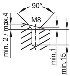
6.2.4 Fixing a sensor with a 90° cone
Bore the hole for the fitting according to the data sheet in compliance with common regulations and standards.
▶ On flat surfaces, make a conical bore hole or use a conical washer.
▶ Make a conical bore hole on tilted or curved surfaces.
7 Electrical connection

The unit must be connected by a qualified electrician.
▶ Observe the national and international regulations for the installation of electrical equipment.
▶ Disconnect power.
▶ Connect the device.
7.1 MEMS sensors with current output (VSA)
Connection of sensors with M12 connector or connecting cable with M12 connector
| M12 |  | Pin 1: L+ |
| Pin 2: Signal output (z axis) | ||
| Pin 3: GND | ||
| Pin 4: Self-test |
Connection of sensors with connecting cable
| Core colour | Signal |
| BN brown | L+ |
| WH white | Signal output |
| BU blue | GND |
| BK black | Self-test |
| Drain wire | Cable shield |
7.2 MEMS sensors with IEPE output (VSM)
Connection of sensors with connecting cable
| Core colour | Signal |
| BN brown | IEPE x axis (if available) |
| WH white | IEPE z axis *) |
| BU blue | GND |
| BK black | Self-test *) |
| GY grey | IEPE y axis (if available) |
| Drain wire | Cable shield |
*) The self-test is only carried out via the z axis.
▶ Connect both cables (BK and WH) to the same terminal of a suitable evaluation unit (e.g. VSExxx).
Connection of sensors with M12 connector
| M12 |  | Pin 1: IEPE x axis (if available) |
| Pin 2: IEPE z axis | ||
| Pin 3: GND | ||
| Pin 4: Self-test | ||
| Pin 5: IEPE y axis (if available) |
7.3 Piezo sensors with IEPE output (VSP)
Connection of sensors with M12 connector
| M12 |  | Pin 1: - |
| Pin 2: IEPE z axis | ||
| Pin 3: - | ||
| Pin 4: GND |
Connection of sensors with connecting cable
| Core colour | Signal |
| BK black | GND |
| WH white | IEPE z axis |
| RD red | No connection |
| Drain wire | Cable shield |
7.4 Connection to the VSE diagnostic electronics
| VSE sensor input | Sensor output | ||||
| S1 | S2 | S3 | S4 | Current output | IEPE |
| 9 | 16 | 20 | 24 | BN: L+ | n.c. (not used) |
| 10 | 15 | 19 | 23 | WH: measured signal | measured signal |
| 11 | 14 | 18 | 22 | BU: GND | GND |
| 12 | 13 | 17 | 21 | BK: self-test | n.c. (not used) /Self-test (if available) |
7.5 Use of screened cables
▶ Use a screened cable to avoid conducted interference.
▶ All machine and electrical parts must be grounded.
▶ VSP devices: Fix the cable directly after the mounting location.

▷ Where several sensors are used on different machines, all devices must be connected to the same ground.
▷ This is to avoid induction loops via the diagnostic electronics.
7.5.1 VSA / VSP devices
Recommendation: Screening on one side (preferably in the control cabinet).
In case of wired devices the screen is connected to the sensor housing and also to any existing M12 connector.
7.5.2 VSM devices
Recommendation: Screening on one side at the machine.
In case of wired devices the screen is connected to the sensor housing and also to any existing M12 connector.
7.6 Connection examples
Recommended connection for sensors with M12 connector or connecting cable with M12 connector; Example VSA001

1:Screen
Recommended connection for sensors with connecting cable; Example VSA004
▶ Do not place the screen at the socket.

1: Screen
2: Drain wire
Recommended connection for VSM sensors with cable plug; Example VSM101
▶ Place the screen at the socket.

1:Drain wire
2:Screen
8 Maintenance, repair and disposal
The operation of the unit is maintenance-free.
Only the manufacturer is allowed to repair the unit.
▶ After use dispose of the device in an environmentally friendly way in accordance with the applicable national regulations.
- 1 PRELIMINARY NOTE
- 1.1 SYMBOLS USED
- 1.2 WARNINGS
- 2 SAFETY INSTRUCTIONS
- 3 TRANSPORT, HANDLING AND STORAGE
- 4 INTENDED USE
- 5 FUNCTION
- 5.1 MEASURING PRINCIPLES / INTERFACES
- 5.2 AXIS ORIENTATION
- 5.3 SELF-TEST
- 6 INSTALLATION
- 6.1 PREPARE CONTACT SURFACE
- 6.2 TYPES OF MOUNTING
- 6.2.1 SCREW
- 6.2.2 GLUE
- 6.2.3 MAGNET
- 6.2.4 FIXING A SENSOR WITH A 90° CONE
- 7 ELECTRICAL CONNECTION
- 7.1 MEMS SENSORS WITH CURRENT OUTPUT (VSA)
- 7.2 MEMS SENSORS WITH IEPE OUTPUT (VSM)
- 7.3 PIEZO SENSORS WITH IEPE OUTPUT (VSP)
- 7.4 CONNECTION TO THE VSE DIAGNOSTIC ELECTRONICS
- 7.5 USE OF SCREENED CABLES
- 7.5.1 VSA / VSP DEVICES
- 7.5.2 VSM DEVICES
- 7.6 CONNECTION EXAMPLES
- 8 MAINTENANCE, REPAIR AND DISPOSAL
Brand : IFM
Model : VSA005
Category : Accelerometer