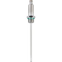
TA2447 - Temperature transmitter IFM - Free user manual and instructions
Find the device manual for free TA2447 IFM in PDF.


User questions about TA2447 IFM
0 question about this device. Answer the ones you know or ask your own.
Ask a new question about this device
Download the instructions for your Temperature transmitter in PDF format for free! Find your manual TA2447 - IFM and take your electronic device back in hand. On this page are published all the documents necessary for the use of your device. TA2447 by IFM.
USER MANUAL TA2447 IFM
Operating instructions
Temperature transmitter
TA1xxx
TA2xxx
Contents
1 Preliminary note 3
1.1 Symbols used 3
1.2 Warnings used 3
2 Safety instructions.... 3
3 Intended use 4
4 Function 4
4.1 Analogue output 4
4.2 IO-Link 4
5 Installation 5
5.1 Use in hygienic areas according to 3-A.... 5
5.2 Use in hygienic areas according to EHEDG 6
5.3 Units with clamp process connection 7
5.4 Units with sealing cone process connection 7
5.4.1 Flush mount hygienic zero-leak using PEEK sealing....7
5.4.2 Flush mount zero-leak using metal-to-metal seal 7
5.5 Units for process adaptation via clamping ring 8
5.6 Units for process adaption via zero void adapters 8
5.7 Using the welding adapter / welding thermowell 8
6 Electrical connection.... 9
7 Parameter setting 10
7.1 Adjustable parameters 10
8 Operation 10
9 Maintenance, repair and disposal 10
10 Factory setting 11
1 Preliminary note
You will find instructions, technical data, approvals and further information using the QR code on the unit / packaging or at www.ifm.com.
1.1 Symbols used
√ Requirement
▶ Instructions
▷ Reaction, result
[...] Designation of keys, buttons or indications
→ Cross-reference

Important note
Non-compliance may result in malfunction or interference.

Information
Supplementary note
1.2 Warnings used

CAUTION
Warning of personal injury
▷ Slight reversible injuries may result.
2 Safety instructions
- The unit described is a subcomponent for integration into a system.
- The system architect is responsible for the safety of the system.
-
The system architect undertakes to perform a risk assessment and to create documentation in accordance with legal and normative requirements to be provided to the operator and user of the system. This documentation must contain all necessary information and safety instructions for the operator, the user and, if applicable, for any service personnel authorised by the architect of the system.
-
Read this document before setting up the product and keep it during the entire service life.
- The product must be suitable for the corresponding applications and environmental conditions without any restrictions.
- Only use the product for its intended purpose (→ Intended use).
- Only use the product for permissible media.
- If the operating instructions or the technical data are not adhered to, personal injury and/or damage to property may occur.
- The manufacturer assumes no liability or warranty for any consequences caused by tampering with the product or incorrect use by the operator.
- Installation, electrical connection, set-up, operation and maintenance of the product must be carried out by qualified personnel authorised by the machine operator.
- Protect units and cables against damage.
3 Intended use
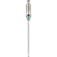
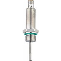
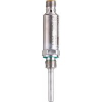
The unit monitors liquids and gases.
The unit detects the medium temperature and converts it into an analogue output signal.
4 Function
4.1 Analogue output
The unit provides an analogue signal proportional to the process value.
The analogue signal is invertible:
- 4...20 mA with setting [OU] = I
- 20...4 mA with setting [OU] = Ineg
The measuring range is scalable: The parameters [ASP] and [AEP] allow for the measuring range to be limited.

Minimum distance between ASP and AEP = 5 °C or 9 °F.
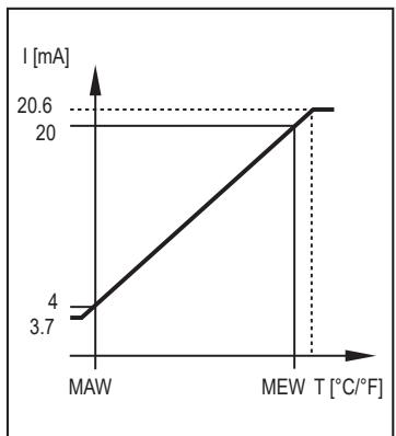
Fig. 1: Maximum measuring range at [OU] = I
MAW: Initial value of the measuring range
MEW: Final value of the measuring range

Fig. 2: Scaled measuring range at [OU] = I
ASP: Analogue start value
AEP: Analogue end value
Within the measuring range, the output signal is between 4 and 20 mA. If the temperature value is outside the limits of the measuring range, the following signal is provided:
| Output signal at [OU] = I | Output signal at [OU] = Ineg | |
| Temperature > AEP | 20...20.6 mA | 4...3.7 mA |
| Temperature > MEW | 20.6 mA | 3.7 mA |
| Temperature < ASP | 4...3.7 mA | 20...20.6 mA |
| Temperature < MAW | 3.7 mA | 20.6 mA |
In case of an internal fault, the output signal reacts according to the parameter set in [FOU] (3.5 mA or 21.1 mA).
4.2 IO-Link
This unit has an IO-Link communication interface which enables direct access to process and diagnostic data. In addition it is possible to set the parameters of the unit while it is in operation. Operation of the unit via the IO-Link interface requires an IO-Link master.
With a PC, suitable IO-Link software and an IO-Link adapter cable, communication is possible while the system is not in operation.
The IODDs necessary for the configuration of the unit, detailed information about process data structure, diagnostic information, parameter addresses and the necessary information about the required IO-Link hardware and software can be found at www.ifm.com.
The IO-Link interface provides the following functions using suitable hardware and software:
- Remote parameter setting of the unit.
- Noise-immune signal transmission without measured value losses.
- Transmission of the parameter settings to a replaced unit or to other units of the same type.
- Display of error and event messages.
- Paperless logging of parameter sets, process values and diagnostic information.
- Evaluation of the process values and diagnostic data via IO-Link master.
- Display of minimum and maximum temperature values.
5 Installation

CAUTION
During installation or in case of mechanical failure, high pressure or hot media can leak from the system.
▷ Risk of injury caused by pressure or burns.
▶ Ensure that the system is free of pressure during installation.
▶ Ensure that no media can leak at the mounting location during installation.
5.1 Use in hygienic areas according to 3-A
▶ Secure clamp sensors with a suitable clamp.
▶ Ensure that the installation of the unit in the system complies with 3-A guidelines.
▶ Use only process adapters with 3-A certification and marked with the 3-A symbol ( → Accessories at www.ifm.com).

▶ For use according to 3-A, take note of the corresponding regulations for cleaning and maintenance.

▶ Not suitable for systems that have to meet the criteria of E1.2 / 63-03 of the 3-A standard 63-03.
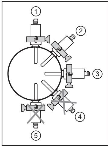
Fig. 3: Installation position for 3-A certification
▶ The positioning of the sensor must be observed to ensure the mounting adapter will self-drain: Do not install the unit in positions 4 and 5.
5.2 Use in hygienic areas according to EHEDG
In case welded adapters are used, the food contact surface must be smooth (surface roughness Ra < 0.8 μm) and the welding has to be done according to EHEDG Guideline 9 and 35.
The sensor is suited for CIP (clean in place) when installed correctly.
▶ Observe the application limits (temperature and material resistance) according to the data sheet.
▶ Ensure that the installation of the unit in the system complies with EHEDG.
▶ Use self-draining installation.
▶ Only use process adapters permitted according to EHEDG with special seals required by the EHEDG position paper.
▶ For any structures in a tank, direct water jet cleaning and cleaning of any dead spaces must be possible.
▶ Adhere to the dimensions shown in the following figure to avoid dead spaces that cannot be cleaned effectively:
L < (D - d).

1: Sealing ring in accordance with EHEDG position paper
2: Adapter
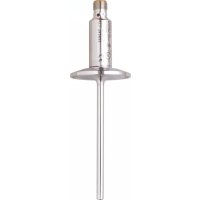
5.3 Units with clamp process connection
The one-piece units of design TA28xx with clamp 1.5" are best suited for a hygienic installation.

Adhere to the installation instructions for use in hygienic areas according to 3-A or EHEDG.
5.4 Units with sealing cone process connection
The units of design TA25xx (G½ sealing cone) and TA11xx (M12 sealing cone) can be adapted to standard process connections using two sealing versions. The following applies to both sealing versions:
▶ Only use accessories from ifm electronic. The optimum function is not ensured when using components from other manufacturers.
▶ Observe the instructions of the adapter.
Use PEEK sealing for 3-A and EHEDG-conform sensor installation.
- For TA25xx units: E43911 (PEEK sealing and sealing ring between housing and process connection).
- For TA11xx units: E43915 (PEEK sealing and sealing ring between housing and process connection).

E43911 / E43915 is not supplied with the unit but must be ordered separately.
▶ Adhere to installation instructions of E43911 / E43915.

The sealing ring between the housing and the process connection can compensate for tolerances and provides protection against the ingress of media in the thread area.
The sealing ring between the housing and the process connection cannot compensate for the system pressure.
5.4.1 Flush mount hygienic zero-leak using PEEK sealing
▶ Insert the PEEK sealing.
• The PEEK sealing is suited for use in hygienic installations to EHEDG and 3-A.
• The PEEK sealing is long-term stable and maintenance-free.
• When the PEEK sealing is mounted several times, check and replace it if necessary.
• The PEEK sealing has been rated for ifm adapters with end stop towards the medium.
▶ Use adapters with leakage ports.
▶ Screw the sensor into the adapter. Recommended tightening torque 20 Nm.

Adhere to the installation instructions for use in hygienic areas according to 3-A or EHEDG.
5.4.2 Flush mount zero-leak using metal-to-metal seal

A long-term stable, maintenance-free fitting without bug traps in the metal-to-metal sealing is only valid for once-only mounting.
▶ Do not use the PEEK sealing.
▶ Screw the sensor into the adapter. Recommended tightening torque 20 Nm.
5.5 Units for process adaptation via clamping ring
The units of design TA22xx can be mounted in the pipe or in the tank directly in contact with the medium via a clamping ring adapter.
Mounting examples:

Fig. 4: Direct installation (e.g. with adapter E30407)

Fig. 5: Installation with protective tube (e.g. with adapter E37421)
5.6 Units for process adaption via zero void adapters
The units of design TA16xx can be mounted in the pipe or in the tank via the zero void adapters.
The zero void adapter assembly ensures dead-zone free installation, easy cleaning and is suitable for use in hygienic areas.
More information at www.ifm.com.
5.7 Using the welding adapter / welding thermowell
General notes on the welding operation:
▶ The welding operation is to be carried out by qualified personnel according to state-of-the-art technology.
▶ Use materials and welding operations that are suitable for the housing material.
▶ Keep the surfaces free from any contamination.
▶ Ensure the careful preparation of the components.
Welding operation:

Fig. 6: Applying the fixing points

Fig. 7: Applying the welding seams
▶ Apply the fixing points of the welding thermowell at equal distance (crosswise) with a sufficient adhesive force.
▶ Apply the welding seams between the fixing points opposite each other.
▶ Ensure sufficient intervals between the individual welding operations to avoid glowing through or warping of the welding thermowell due to overheating.
After completion of the welding operation:
▶ Let the workpiece cool down.
▶ Slightly grease the thread using a lubricating paste which is suitable and approved for the application.
▶ Screw the sensor into the adapter and tighten. Tightening torque: 30...50 Nm.
6 Electrical connection
The device must be connected by a qualified electrician.
Observe the national and international regulations for the installation of electrical equipment.
Voltage supply according to EN 50178, SELV, PELV.
▶ Disconnect power.
▶ Connect the unit as follows:

Fig. 8: Wiring diagram
Operation as 2-wire unit (1)
| Pin | Connection |
| 1 | L+ |
| 2 | Analogue signal temperature |
Operation as 4-wire unit (2)
| Pin | Connection |
| 1 | L+ |
| 2 | Analogue signal temperature |
| 3 | L- |
| 4 | IO-Link |
7 Parameter setting
Using an IO-Link capable parameter setting tool, the following options are available:
- Reading current process values.
- Reading, changing and saving current parameter settings and transmitting them to other units of the same type.
▶ Connect the unit via the IO-Link interface to a PC or PLC with suitable parameter setting software.

You will find all information about the required IO-Link hardware and software at www.ifm.com.
7.1 Adjustable parameters
| Parameter | Description | |
| OU | I: 4...20 mA Ineg: 20...4 mA | |
| ASP | Analogue start point | |
| For OU2 = I | Measured temperature value at which 4 mA is provided. | |
| For OU2 = Ineg | Measured temperature value at which 20 mA is provided. | |
| AEP | Analogue end point | |
| For OU2 = I | Measured temperature value at which 20 mA is provided. | |
| For OU2 = Ineg | Measured temperature value at which 4 mA is provided. | |
| COF | Zero-point calibration. Setting range: ±10 °C in steps of 0.1 °C. The internal measured value "0" is shifted by this value. | |
| FOU | Behaviour of the output in case of an internal fault. On: The analogue signal goes to 21.1 mA. OFF: The analogue signal goes to 3.5 mA. | |
| Uni | Unit of measurement for medium temperature: °C or °F. | |
8 Operation
After power-on the device is in the normal operating mode.
9 Maintenance, repair and disposal
The operation of the unit is maintenance-free.
Only the manufacturer is allowed to repair the unit.
▶ After use dispose of the device in an environmentally friendly way in accordance with the applicable national regulations.
10 Factory setting
| Parameter | Factory setting | User settings |
| OU2 | I | |
| COF | 0 | |
| FOU2 | OFF |
Factory setting for [ASP] and [AEP] and the unit [Uni] → Technical data at www.ifm.com.
- CONTENTS
- 1 PRELIMINARY NOTE
- 1.1 SYMBOLS USED
- 1.2 WARNINGS USED
- 2 SAFETY INSTRUCTIONS
- 3 INTENDED USE
- 4 FUNCTION
- 4.1 ANALOGUE OUTPUT
- 4.2 IO-LINK
- 5 INSTALLATION
- 5.1 USE IN HYGIENIC AREAS ACCORDING TO 3-A
- 5.2 USE IN HYGIENIC AREAS ACCORDING TO EHEDG
- 5.3 UNITS WITH CLAMP PROCESS CONNECTION
- 5.4 UNITS WITH SEALING CONE PROCESS CONNECTION
- 5.4.1 FLUSH MOUNT HYGIENIC ZERO-LEAK USING PEEK SEALING
- 5.4.2 FLUSH MOUNT ZERO-LEAK USING METAL-TO-METAL SEAL
- 5.5 UNITS FOR PROCESS ADAPTATION VIA CLAMPING RING
- 5.6 UNITS FOR PROCESS ADAPTION VIA ZERO VOID ADAPTERS
- 5.7 USING THE WELDING ADAPTER / WELDING THERMOWELL
- GENERAL NOTES ON THE WELDING OPERATION
- WELDING OPERATION
- AFTER COMPLETION OF THE WELDING OPERATION
- 6 ELECTRICAL CONNECTION
- 7 PARAMETER SETTING
- 7.1 ADJUSTABLE PARAMETERS
- 8 OPERATION
- 9 MAINTENANCE, REPAIR AND DISPOSAL
- 10 FACTORY SETTING
Brand : IFM
Model : TA2447
Category : Temperature transmitter