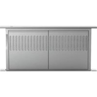
HD30 - Fan Fisher & Paykel - Free user manual and instructions
Find the device manual for free HD30 Fisher & Paykel in PDF.


| Product type | Downdraft ventilation system |
| Brand | Fisher & Paykel |
| Model | HD30 (30 inches) |
| Dimensions (W x D x H) | 762 x 330 x 357 mm (30 x 13 x 14 in) |
| Net weight (unit only) | 16 kg (35 lb) |
| Power supply | 120 V ~ 60 Hz, 15 A, dedicated circuit |
| Maximum power | 2.8 A (compatible fan) |
| Motor type | Internal or remote motor (depending on configuration) |
| Recommended duct diameter | 6 in (152 mm) for internal fan, 10 in (254 mm) for remote fan |
| Number of speeds | Variable (slider) |
| Telescopic function | Motorized elevation and lowering |
| Control type | On/off button + speed slider |
| Filters | 2 aluminum grease filters, washable |
| Lighting | Not integrated |
| Trim material | Stainless steel |
| Installation | Integrated into countertop, external exhaust |
| Compatibility | Cooking surfaces (gas, induction, electric) |
| Safety | Microswitches on filters, anti-lift safety switch, grounding |
| Recommended maintenance | Monthly filter cleaning, regular cleaning with mild detergent |
| Warranty | 2 years parts and labor (residential use) |
| Replacement filter reference | 290317 (HD30) |
| Country of manufacture | New Zealand (brand) |
Frequently Asked Questions - HD30 Fisher & Paykel
User questions about HD30 Fisher & Paykel
0 question about this device. Answer the ones you know or ask your own.
Ask a new question about this device
Download the instructions for your Fan in PDF format for free! Find your manual HD30 - Fisher & Paykel and take your electronic device back in hand. On this page are published all the documents necessary for the use of your device. HD30 by Fisher & Paykel.
USER MANUAL HD30 Fisher & Paykel
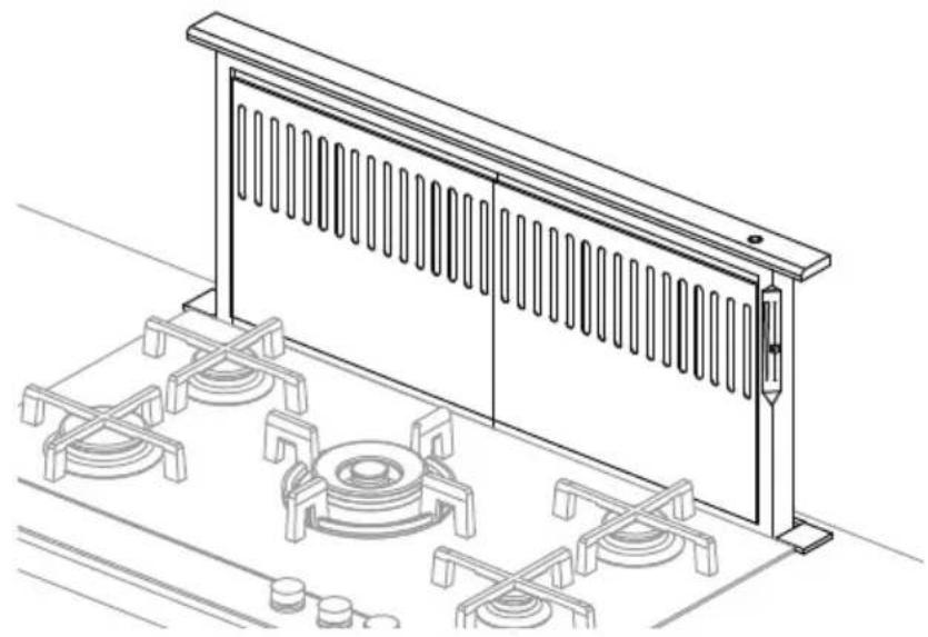
HD30 and HD36 Vent models
HBD600I and HBD1200E Blower models
SYSTÈME DE VENTILATION TÉLESCOPIQUE À ASPIRATION DESCENDANTE
Introduction 3
Safety and warnings 4
Venting requirements 6
Electrical requirements 7
Installation instructions 8
Operating instructions 25
Cleaning and maintenance 26
Troubleshooting 27
Parts and accessories 29
Wiring diagram 30
Limited Warranty 32
IMPORTANT!
SAVE THESE INSTRUCTIONS
The models shown in this user guide may not be available in all markets and are subject to change at any time. For current details about model and specification availability in your country, please go to our website www.fisherpaykel.com or contact your local Fisher & Paykel dealer.
Registration
Register your product with us so we can provide you with the best service possible.
To register your product visit our website: www.fisherpaykel.com
Thank you for purchasing a Fisher & Paykel product. This Installation and Use and Care Guide contains valuable information on how to properly install, operate and maintain your new Downdraft Vent System for years of safe and enjoyable service.
To serve you better, please fill out and submit your Product Registration by visiting our website at www.fisherpaykel.com and selecting ‘Customer Care’ on the home page and then select ‘Product Registration’. In addition, keep this manual handy, as it will help answer questions that may arise as you use your new appliance.
For your convenience, product questions can be answered by a Fisher & Paykel Customer Care Representative by phone: 1-888-936-7872, or email: support@fisherpaykel.com
Note: write the Model, Code and Serial Numbers on this page for references.
Vent Model Number____ Code____ Serial Number____
Blower Model Number____ Code____ Serial Number____
Note: inspect the product to verify that there is no shipping damage. If any damage is detected, call the shipper and initiate a damage claim. Fisher & Paykel is not responsible for shipping damage where Fisher & Paykel is not the shipper.
DO NOT discard any packing material (box, pallet, straps) until the unit has been inspected.
natural_image
Technical line drawing of a structural panel with multiple circular components and mounting brackets (no text or symbols)! WARNING!
35 lb (16 kg)
(HC30)
44 lb (20 kg)
(HC36)
11 lb (5 kg)
(HBD600I)
33 lb (15 kg)
(HBD1200E)
Weight Hazard
The appliance is heavy. Please ensure adequate care is taken when installing the appliance to prevent personal injury. Weight of the products are 35 lb (16 kg) HC30 / 44 lb (20 kg) HC36 / 11 lb (5 kg) HBD600I / 33 lb (15 kg) HBD1200E
WARNING!

Electric Shock Hazard
Always disconnect the appliance from the mains power supply before carrying out any maintenance or repairs.
Installation work and electrical wiring must be done by qualified person(s) in accordance with all applicable codes and standards, including fire-rated construction.
Failure to do so can result in death, electric shock, fire or injury to persons.
IMPORTANT SAFETY INSTRUCTIONS
READ THE ENTIRE SET OF INSTRUCTIONS BEFORE INSTALLING OR USING THIS APPLIANCE.
Manuals can also be found on our website www.fisherpaykel.com
- CAUTION: For general ventilating use only. Do not use to exhaust hazardous or explosive materials and vapors.
-
WARNING! To reduce the risk of fire, electric shock, or injury to persons, observe the following:
-
Use this unit only in the manner intended by the manufacturer. If you have questions, contact the manufacturer. For residential use only.
- Before servicing or cleaning unit, switch power off at service panel and lock the service disconnecting means to prevent power from being switched on accidentally. When the service disconnecting means cannot be locked, securely fasten a prominent warning device, such as a tag, to the service panel.
-
Installation work and electrical wiring must be done by qualified person(s) in accordance with all applicable codes and standards, including fire-rated construction.
-
Sufficient air is needed for proper combustion and exhausting of gases through the flue (chimney) of fuel burning equipment to prevent back drafting. Follow the heating equipment manufacturer's guideline and safety standards such as those published by the National Fire Protection Association (NFPA), and the American Society for Heating, Refrigeration and Air Conditioning Engineers (ASHRAE), and the local code authorities.
- When cutting or drilling into wall or ceiling, do not damage electrical wiring and other hidden utilities.
- Ducted fans must always be vented to the outdoors.
-
This appliance must be grounded
-
CAUTION: To reduce risk of fire and to properly exhaust air, be sure to duct air outside – Do not vent exhaust air into spaces within walls or ceilings or into attics, crawl spaces, or garages.
- WARNING: To reduce the risk of fire, use only metal ductwork.
• NOTE: Suitable for use with solid state speed controls. - CAUTION: To reduce the risk of fire and electric shock, install this appliance only with remote blower models rated maximum 2.8 A, and are suitable for use with solid state speed controls.
-
WARNING: To reduce the risk of a range top grease fire:
-
Never leave surface units unattended at high settings. Boilovers cause smoking and greasy spillovers that may ignite. Heat oils slowly on low or medium settings.
- Always turn hood ON when cooking at high heat or when flambéing food (ie Crepes Suzette, Cherries Jubilee, Peppercorn Beef Flambé).
- Clean ventilating fans frequently. Grease should not be allowed to accumulate on fan or filter.
- Use proper pan size. Always use cookware appropriate for the size of the surface element.
- WARNING: To reduce the risk of injury to persons in the event of a range top grease fire, observe the following*:
- SMOTHER FLAMES with a close-fitting lid, cookie sheet, or metal tray, then turn off the burner. BE CAREFUL TO PREVENT BURNS. If the flames do not go out immediately, EVACUATE AND CALL THE FIRE DEPARTMENT.
- NEVER PICK UP A FLAMING PAN - You may be burned.
- DO NOT USE WATER, including wet dishcloths or towels - a violent steam explosion will result.
-
Use an extinguisher ONLY if:
-
You know you have a Class ABC extinguisher, and you already know how to operate it.
- The fire is small and contained in the area where it started.
- The fire department is being called.
-
You can fight the fire with your back to an exit.
-
WARNING: Unplug or disconnect the appliance from the power supply before servicing or cleaning.
- WARNING: All wall and floor openings where the vent hood is installed must be sealed.
READ AND SAVE THESE INSTRUCTIONS
Determine which venting method is best for your application. Ductwork can extend either through the wall or the roof.
The length of the ductwork and the number of elbows should be kept to a minimum to provide efficient performance. The size of the ductwork should be uniform. Do not install two elbows together. Use duct tape to seal all joints in the ductwork system. Use caulking to seal exterior wall or floor opening around the cap.
Flexible ductwork is not recommended. If it is used, each foot of flexible ductwork used is equivalent to two feet of straight metal ductwork when calculating the ductrun length. Thus, a flexible elbow equals two standard elbows.
Make sure there is proper clearance within the wall or floor for exhaust duct before making cutouts. Do not cut a joist or stud unless absolutely necessary. If a joist or stud must be cut, then a supporting frame must be constructed. For best results, internal blowers should use 6" (152 mm) round ducting and remote blowers should transition to 10" (254 mm) round duct as soon as possible. If small ducting is used, it should be transitioned to 10" (254 mm) round as soon as possible.
WARNING!
To reduce the risk of fire, use only metal ductwork.
CAUTION!
To reduce risk of fire and to properly exhaust air, be sure to duct air outside - do not vent exhaust air into spaces within walls or ceilings or into attics, crawl spaces or garages.
Cold weather installations (not included)
An additional back draft damper should be installed to minimize backward cold air flow and a nonmetallic thermal break should be installed to minimize conduction of outside temperatures as part of the vent system. The damper should be on the cold air side of the thermal break. The break should be as close as possible to where the vent system enters the heated portion of the house.
WARNING!
- Venting system MUST terminate outside the home.
• DO NOT terminate the ductwork in an attic or other enclosed space. - DO NOT use 4" (102 mm) laundry-type wall caps.
- Flexible-type ductwork is not recommended.
• DO NOT obstruct the flow of combustion and ventilation air. - Failure to follow venting requirements may result in a fire.
A 120 volt, 60 Hz AC-only electrical supply is required on a dedicated 15 amp fused circuit. A time-delay fuse or circuit breaker is recommended. The fuse must be sized per local codes in accordance with the electrical rating of this unit as specified on the serial/rating plate located inside the unit near the field wiring compartment. THIS UNIT MUST BE CONNECTED WITH COPPER WIRE ONLY. Wire sizes must conform to the requirements of the National Electrical Code, ANSI/NFPA 70 – latest edition, and all local codes and ordinances. Wire size and connections must conform with the rating of the appliance. Copies of the standard listed above may be obtained from:
National Fire Protection Association
Batterymarch Park
Quincy, Massachusetts 02269
This appliance should be connected directly to the fused disconnect (or circuit breaker) through flexible, armored or nonmetallic sheathed copper cable. Allow some slack in the cable so the appliance can be moved if servicing is ever necessary. A UL Listed, 12 " (12.7 mm) conduit connector must be provided at each end of the power supply cable (at the appliance and at the junction box).
When making the electrical connection, cut a 1¼" (32 mm) hole in the wall. A hole cut through wood must be sanded until smooth. A hole through metal must have a grommet.
IMPORTANT!
- Use this unit only in the manner intended by the manufacturer. If you have any questions, contact the manufacturer.
- Before servicing or cleaning unit, switch power off at service panel and lock the service disconnecting means to prevent power from being switched on accidentally. When the service disconnecting means cannot be locked, securely fasten a prominent warning device, such as a tag, to the service panel.
WARNING!
• Electrical ground is required on this downdraft unit.
- If cold water pipe is interrupted by plastic, nonmetallic gaskets or other materials, DO NOT use for grounding.
• DO NOT ground to a gas pipe.
- DO NOT have a fuse in the neutral or grounding circuit. A fuse in the neutral or grounding circuit could result in electrical shock.
- Check with a qualified electrician if you are in doubt as to whether the downdraft unit is properly grounded.
- Failure to follow electrical requirements may result in a fire.
INSTALLATION INSTRUCTIONS
Downdraft unit contents of packaging
natural_image
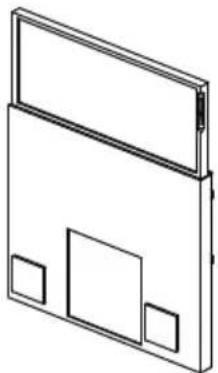
Isometric line drawing of a rectangular device with two internal compartments and a top panel (no text or symbols)Downdraft unit (1)

Installation instructions User guide manual (1)
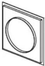
10" (254 mm) remote blower connection plate (1)

End cap (2)
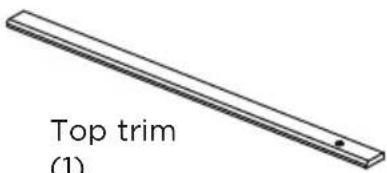
Top trim (1)

Under counter mounting bracket (2)

Support leg
mounting bracket
(2)
natural_image
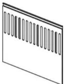
Simple line drawing of a rectangular panel with vertical slots, no text or symbols presentGrease filter (2)

Over counter mounting bracket (2)

^9/32 " (7 mm) nut
(2)

^3/_16 " (5 mm) screw
(2)

^5/_16 " (8 mm) screw
(6)
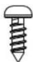
^19/_32 " (15 mm)
Self tapping screw
(6)
Internal blower (HBD600I) contents of packaging
natural_image
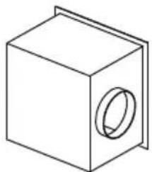
Simple line drawing of a 3D cube with a circular hole on one face (no text or symbols)Internal blower box (1)
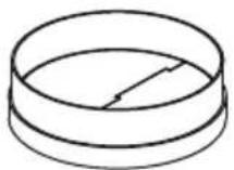
6" (152 mm) diameter back draft damper (1)
Remote blower (HBD1200E) contents of packaging

natural_image
Exterior view of a rectangular electronic enclosure with a grid-patterned front panel (no text or symbols)Remote blower (1)
natural_image
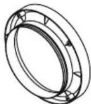
Technical line drawing of a mechanical ring or bearing assembly (no text or symbols)Duct collar plate (1)
INSTALLATION INSTRUCTIONS
Product dimensions
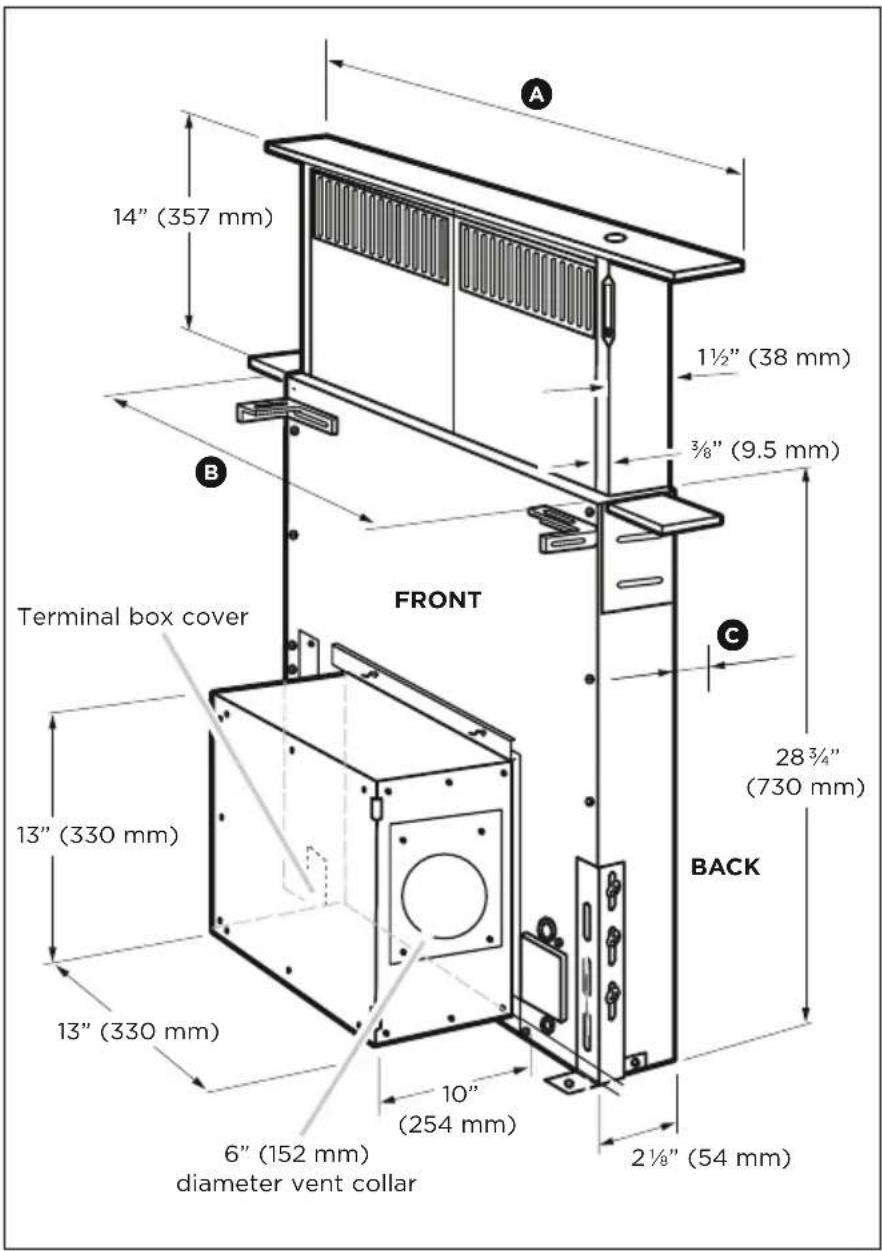

Remote blower (HBD1200E)

Remote blower connection plate (can also be mounted on the back of appliance)
Downdraft unit and internal blower box (HBD600I) which can also be mounted on the back of the appliance
HD30 HD36
| PRODUCT DIMENSIONS inches (mm) inches (mm) | ||
| A | Top trim width 30” (762) 36” (914) | |
| B | Width of product 27” (686) 33” (838) | |
| C | Minimum distance to rear of the cabinet or wall 1” (25) 1” (25) | |
| Length of power cord N/A N/A | ||
IMPORTANT!
Actual product dimensions may vary by ±332 " (2 mm).
Please read the entire instructions before installing the downdraft vent system.
Cabinet cutout dimensions
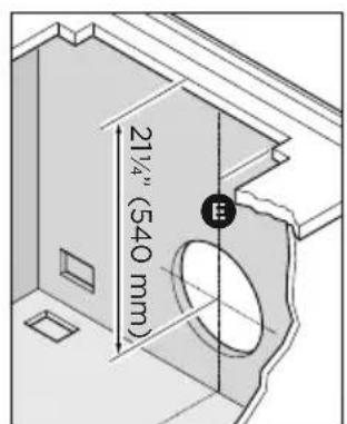
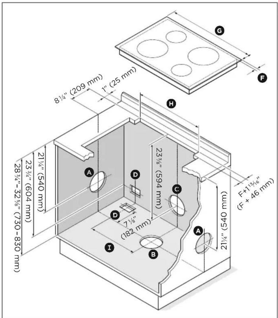
CUTOUT LOCATION
| A | Internal blower left/right 6” (152 mm) ducting |
| B | Internal blower down 6” (152 mm) ducting |
| C | Internal blower rear 6” (152 mm) ducting |
| D | Remote blower power cord cutout down or to the rear |
| E | Remote blower rear 10” (254 mm) ducting |
| F | Cooktop overhang |
HD30 HD36
| INSTALLATION DIMENSIONS inches (mm) inches (mm) | |||
| G | Minimum width of cooktop 28” (711) 34” (864) | ||
| H | Downdraft cutout width 27 12 ” (699) 33 12 ” (851) | ||
| I | Remote blower power cord cutout width from center | 9” (230) 12” (306) | |
WARNING!
To reduce the risk of fire, use only metal ductwork. Do not use flexible plastic ducting.
CAUTION!
To reduce risk of fire and to properly exhaust air, be sure to duct air outside - Do not vent exhaust air into spaces within walls or ceilings or into attics, crawl spaces, or garages.
Compatible blowers with the downdraft vent system
• Internal blower model HBD6001.
- Remote blower model HBD1200E or Remote Blower Models max 2.8 A.
- This downdraft unit may only be used in connection with the above Fisher & Paykel internal or remote blowers.
Compatible cooktops with the downdraft vent system
The Downdraft Vent System is meant to be installed with residential use cooktops, cooktops/oven combinations, freestanding ranges WITHOUT backguards and range tops. This product is not recommended for use with ranges which may require additional space behind the range for oven venting OR with freestanding ranges WITH backguards. Always consult all product installation instructions for correct dimensions and clearances.
IMPORTANT!
Make certain any cooktop installed is appropriate for use with a downdraft vent system.
Venting requirements
Attention should be given to ensure that any applicable regulations concerning the discharge of exhaust air are fulfilled.
For optimal efficiency use the shortest and straightest duct route possible and use rigid or semi-rigid ducting for reduced noise and increased airflow. For best results, internal blowers should use 6" (152 mm) round ducting and remote blowers should use 10" (254 mm) round ducting. Flexible metal ducting should only be used as a last resort (ie in difficult installations) and if used ensure that it is straight and smooth and extended as much as possible.
Make sure there is proper clearance within the wall or floor for exhaust duct before making cutouts. Do not cut a joist or stud unless absolutely necessary. If a joist or stud must be cut, then a supporting frame must be constructed.
CAUTION!
To reduce the risk of fire and electric shock, install this appliance only with remote blower models rated maximum 2.8 A, and are suitable for use with solid state speed controls.
Plan the ductwork
The internal blower can be mounted to the front or back of the downdraft unit and be ducted in multiple directions: left, right, down, forward or backwards. The remote blower can be ducted downwards from the front or back of the downdraft unit.
In the event of installations where the blower is located on the back of the downdraft unit, it is advised to leave an access door or opening to reach the bottom of the downdraft unit, as well as where the wiring box and blower is located should service be needed.
Calculate the duct run length
The ductwork length should not exceed 55 equivalent feet (16.7 m) for 6" (152 mm) round duct, or 75 equivalent feet (22.9 m) for 10" (254 mm) round duct. Calculate the length of the ductwork by adding the equivalent feet listed in the table below for each piece of duct in the complete system. If flexible metal ductwork is used, each foot (312 mm) of flexible metal ductwork is equivalent to two feet (617 mm) of straight metal ductwork when calculating the duct run length.
For best results the size of the ductwork should be uniform and use no more than three 90° elbows. Make sure that there is a minimum of 24" (607 mm) of straight duct between elbows if more than one is used. Round duct is recommended instead of rectangular duct especially if elbows are needed. Rectangular duct should be transitioned to minimum 6" (152 mm) round for internal blowers and 10" (254 mm) round for remote blowers as soon as possible.
EQUIVALENT LENGTH EXAMPLE CALCULATION
| 45° elbow | 5 feet (1.5 m) | 9 feet straight duct | 9 feet (2.8 m) |
| 90° elbow | 7 feet (2.1 m) | 2 x 90° elbows | 14 feet (4.3 m) |
| 90° flat elbow | 12 feet (3.7 m) | Wall cap | 0 feet (0.0 m) |
Wall cap 0 feet (0.0 m) Complete system 23 feet (7.0 m)
WARNING!
• This appliance is heavy and requires two persons for unpacking and installation.
- Installation work and electrical wiring must be done by qualified person(s) in accordance with all applicable codes and standards.
IMPORTANT!
- Wear gloves to protect against sharp edges.
-
When planning the cutout for the downdraft unit:
-
Draw both the cooktop and downdraft unit cutouts on the countertop before making any cuts.
- Check that there is enough room in the cabinet for both the cooktop and the downdraft unit. Failure to follow these warnings could result in damage to the countertop.
- To avoid damage to motor bearings and impellers, keep drywall spray, construction dust, etc. away from the blower.
The manufacturer is not liable for any damage caused by not following these instructions.
① Preparing for installation
Before installing your downdraft vent system:
- Please read the instructions carefully.
- Unpack the downdraft unit and place on a flat protected surface.
- Ensure the voltage (V) and the frequency (Hz) indicated on the serial plate match the voltage and frequency of the installation site.
- Check that the area around the installation area is clear of any electrical cables and pipes etc.
- Be aware of kitchen cabinets and splash backs in the area of the downdraft vent system and the cooktop. Ensure that the area where the downdraft unit rises is free of obstacles. Also be aware performance may be reduced by strong drafts from windows or doors etc.
- The downdraft unit surfaces can be damaged during installation if grazed or knocked by tools. Please take care to protect the surfaces during installation.
- Temporarily mark the center of the cooktop according to the information given in the 'Installation instructions – Cabinet cutout dimensions' section.
- The downdraft unit is installed directly behind the cooktop. For easiest installation, install the downdraft vent system first, then the cooktop.
- Remove any cardboard packaging from within the blower impeller.
② Prepare the downdraft unit for the intended blower
Internal blower
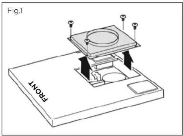
- Remove the 10" (254 mm) blower connection plate from the front of the downdraft unit Fig.1.
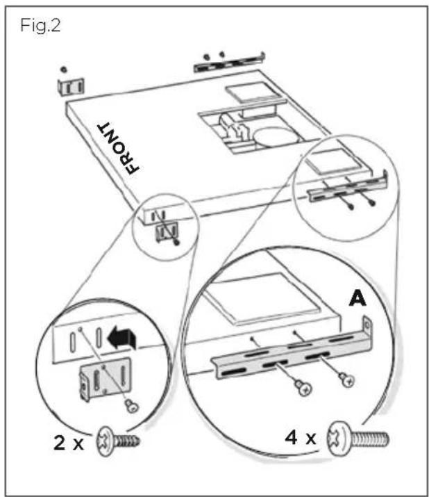
- Attach the over counter mounting brackets in place with the two 316 " (5 mm) screws provided Fig.2.
- Screw the support leg mounting brackets to the side of the downdraft unit using two 516 " (8 mm) screws each, do not fully tighten the screws. The brackets are different for the right and the left side. Attach them with mounting clip (A) pointing up.
Remote blower
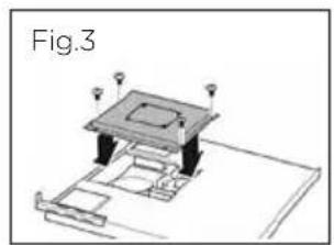
- The downdraft unit comes ready for installation with the 10" (254 mm) remote blower connection plate installed on the front of downdraft unit and the cover plate installed onto the back.
- To connect the remote blower to the back of the downdraft unit swap the plates over (see Fig. 3 and 4).
- Attach the over counter mounting brackets in place with the two 316 " (5 mm) screws provided Fig.2.
- Screw the support leg mounting brackets to the side of the downdraft unit using two 516 " (8 mm) screws each, do not fully tighten the screws. The brackets are different for the right and the left side. Attach them with mounting clip (A) pointing up.
natural_image
Architectural floor plan sketch labeled Fig.3, showing structural layout with no text or symbols on the diagram itself.
INSTALLATION INSTRUCTIONS
③ Temporarily insert the downdraft into the cabinet
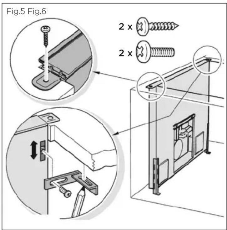
- With the assistance of another person, lift the downdraft unit into the prepared cutout in the cabinet. The over counter mounting brackets should rest on the countertop.
- Secure the downdraft unit to the countertop with two ^19/32 " (15 mm) screws.
- Install the under counter mounting brackets underneath the countertop for additional support. First, loosely screw the brackets into the sliding nuts in the downdraft unit using 316 " (5 mm) screws and push them up under the countertop. Pre-drill the mounting holes into the countertop from underneath. Check that the mounting screws are the proper length and will not extend through the countertop surface when tightened. Failure to follow these instructions could result in damage to the countertop surface Fig.5.
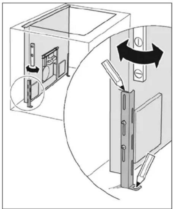
- Level and align the downdraft unit in the cabinet. Push the support leg mounting bracket on each side down against the cabinet floor. Mark the top edge of the mounting bracket on the downdraft unit and the mounting holes on the cabinet floor Fig.6.
natural_image
Diagram showing a door lock mechanism with directional arrows indicating movement, no text or symbols present④ Remove the downdraft from the cabinet
- Remove the screws from the countertop and lift the downdraft unit back out of the cabinet.
• Pre-drill the marked mounting holes in the cabinet floor.
- Tighten the support leg mounting brackets on the unit at the pre-marked positions
- Place the downdraft unit on a flat protected surface to prevent damage in order to install the blower.
⑤ Install the internal or remote blower
• For internal blower installation refer to page 17.
• For remote blower installation refer to page 18.
Note: this downdraft unit may only be used in connection with Fisher & Paykel internal or remote blowers.
Internal blower installation in one of the following three options:
Option 1: Internal blower, front installation for venting left, right or down
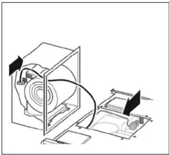
- Disconnect the cable from inside the downdraft unit. Plug in that same cable from the downdraft unit into the internal blower Fig.7.
- Turn the venting collar on the internal blower box to the desired direction - left, right or down.
- Mount the internal blower box to the housing using four screws Fig.8.
- Continue to the 'Prepare for electrical connection' section on page 20.
natural_image
Technical line drawing of an open refrigerator with internal components and wiring (no text or symbols)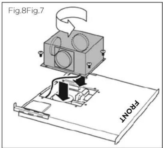
Option 2: Internal blower, back installation for venting left, right or down
- The internal blower box can also be installed on the back of the downdraft unit to accommodate the installation of a cooking range, range top or wall oven / cooktop in front of the downdraft unit.
- Remove the large cover on the back of the downdraft unit Fig.9.
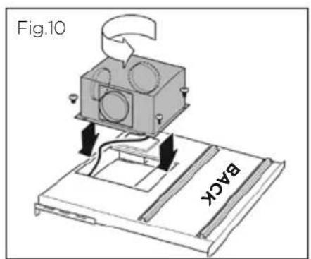
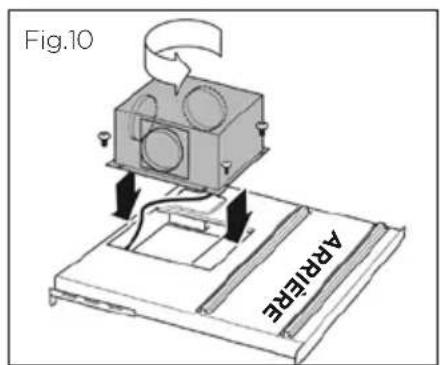
- Turn the venting collar on the blower box to the desired direction – left, right or down. Disconnect the cable from inside the downdraft unit. Plug in that same cable from the downdraft unit into the internal blower and mount the blower box to the housing using four screws Fig.10.
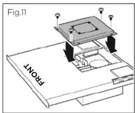
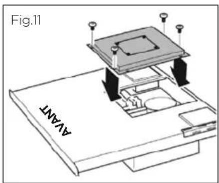
- When finished, mount the previously removed cover onto the front of the downdraft unit Fig.11.
- Continue to the 'Prepare for electrical connection' section on page 20.

Remote blower installation in one of the following three options:
- Make sure that the discharge end of the remote blower faces away from the direction of the prevailing winds.
- Remove any cardboard packaging from within the blower impeller.
- Remove the cover from the remote blower, then remove the wiring box cover and screws.
- Attach an appropriate UL Listed strain relief in the knockout. Note: for most installations, it is recommended that the strain relief be installed so that it can be tightened from inside the remote blower housing.
- Reattach the wiring box cover loosely, it will be removed again later.
Option 1: Wall installation
- Choose a location on an outside wall where no wall studs, wires, pipes, etc. run through the opening area. A minimum distance of 24" (610 mm) from the remote blower to the ground may be required depending on local code. Make sure to leave room for anticipated snowfall in your region.
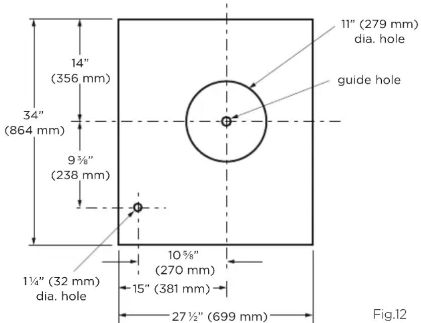
- Drill the guide hole in the center of the 11" (279 mm) diameter opening area.
- Mark a 27 ^1/2 " x 34" (699 x 864 mm) rectangle on wall as indicated in Fig.12.
- Cut a rectangular hole in the siding only. Do not cut sheathing. Nail down all siding ends.
- Mark an 11" (279 mm) diameter circle around guide hole as indicated in Fig.12.
- Mark the center of the 1 ^1/4 " (32 mm) diameter hole for electrical wiring as indicated in Fig.12.
- Cut an 11" (279 mm) diameter hole in the sheathing.
- Drill the 1 14 " (32 mm) diameter electrical wiring hole.
- Run a large bead of caulk on the back side of the housing along the outer edge.
- Center the remote blower ring in the 11" (279 mm) diameter hole, making sure that the 1¼" (32 mm) diameter electrical wiring hole lines up with the hole in the wiring box.
- Attach the remote blower to the wall using screws appropriate for your installation. All four holes in the back panel must be filled to prevent moisture that may get inside the remote blower housing from leaking into the home.
- Seal all around the mounting screw heads with caulk.
- Continue to the 'Prepare for electrical connection' section on page 20.
Option 2: Sloped roof installation
(For flat roof installations see Option 3)
- Choose location on the rear slope of the roof that minimizes vent run.
Avoid obstacles such as TV leads, electric lines, etc. If the remote blower top is level with the roof peak, it will not be seen from the street. Remember this location as you work from the inside of the roof space.
• Mark a point half way between the rafters and drill a guide hole at this point. - From the outside, using the guide hole as a starting point, mark the rectangular cut-out as indicated in Fig.12. Remove ONLY the roof shingles in THIS AREA.
- Mark an 11" (279 mm) diameter circle around guide hole as indicated in Fig.12.
- Mark the center of the 1¼" (32 mm) diameter hole for electrical wiring as indicated in Fig.12.
- Cut out the roof boards along the 11" (279 mm) diameter circle.
- Drill the 1¼" (32 mm) diameter electrical wiring hole.
- Remove the roofing nails from the upper two-thirds of the shingles to allow the back flashing sheet on the remote blower housing to fit under them.
- Center the remote blower ring in the 11" (279 mm) diameter hole, making sure that the 1¼" (32 mm) diameter electrical wiring hole lines up with the hole in the wiring box.
- Attach the remote blower to roof or frame using screws appropriate for your installation. All four holes in the back panel must be filled to prevent moisture that may get inside the remote blower housing from leaking into the home.
- Seal all the shingles around the remote blower housing, flashing sheet, and mounting screw heads or frame with roofing cement. The top and side flanges of the back plate may be covered with trim. It is recommended that electrical connection be made and checked first. Do not block the vent grill opening at the bottom of the trim. Doing so will decrease blower performance.
- Continue to the 'Prepare for electrical connection' section on page 20.
Option 3: Flat roof installation
- Locate the 11" (279 mm) diameter hole between rafters.
- Build a sloping base that will mount the remote blower at a minimum pitch of 2 12 (64 mm) see Fig.13 for an example showing 5" (127 mm) pitch.
• Weatherproof the base as required. - Locate the base so that the remote blower's vent aligns with the 11" (279 mm) diameter hole and the blower sits evenly on the base with no gaps.
Note: Make sure that the discharge end of the remote blower faces away from the direction of prevailing winds. - Use dimensions from Fig.12 to locate the 1 14 " (32 mm) diameter wiring hole.
- Continue from point 8 from the previous ‘sloped roof installation’ section.

INSTALLATION INSTRUCTIONS
⑥ Prepare for electrical connection
Downdraft unit
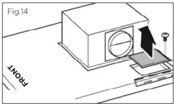
- Remove the cover of the terminal box from the downdraft unit Fig.14.
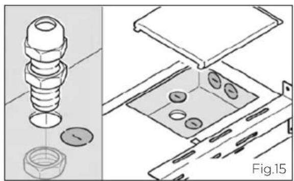
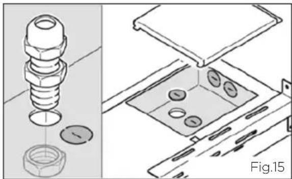
- Decide whether the power source should enter the downdraft unit from below or from the back and remove the respective knock out. Install a UL listed strain relief or conduit fitting (not included) in the knock out Fig.15.
- If the downdraft unit is being installed with a remote blower, remove the knock out for the control cable.
- With the assistance of another person, lift the downdraft unit into the prepared cutout in the cabinet. The over counter mounting brackets should rest on the countertop.
- Secure the downdraft unit to the floor and countertop with screws into the previously drilled holes Fig.16.
natural_image
Technical illustration showing a bolt assembly process with a magnified view of the component (no text or symbols present)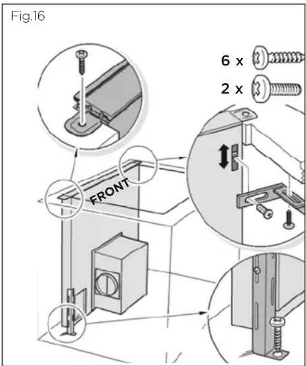
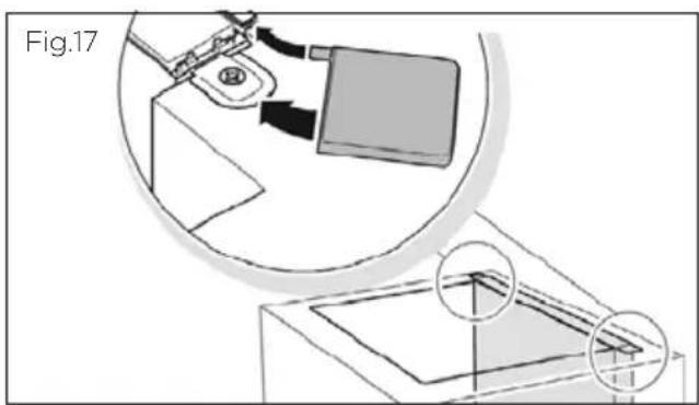
- Push the end caps into place on the downdraft unit on top of the counter and lock them in place Fig.17.
natural_image
Technical diagram showing mechanical assembly with magnified detail (no text or symbols)⑦ Electrical connection
WARNING!
- Electrical wiring must be done by qualified person(s) in accordance with all applicable codes and standards and the unit must be grounded.
- This downdraft unit may only be used in connection with Fisher & Paykel internal or remote blowers.
- Unplug or disconnect the appliance from the power supply before servicing or cleaning.
Electrical requirements
A 120 volt, 60 Hz AC-only electrical supply is required on a separate 15 amp circuit, fused on both sides of the line. A time-delay fuse or circuit breaker is recommended. The fuse must be sized per local codes in accordance with the electrical rating of this downdraft unit as specified on the serial/rating plate located inside the downdraft unit near the field wiring compartment.
This downdraft unit must be connected with copper wire only. Wire sizes must conform to the requirements of the National Electrical Code, ANSI/NFPA 70 -latest edition, and all local codes and ordinances. Wire size and connections must conform with the rating of the appliance. Copies of the standard listed above can be obtained from:
National Fire Protection Association
Battery March Park
Quincy, Massachusetts 02269
This appliance should be connected directly to the fuse disconnect (or circuit breaker) through flexible, armored or non-metallic sheathed copper cable. Allow some slack in the cable so the appliance can be moved if servicing is ever necessary. A UL Listed strain relief or 12 " (12.7 mm) conduit connector must be provided at each end of the power supply cable (at the appliance and at the junction box).
When making the electrical connection, cut a 1¼" (32 mm) hole in the wall. A hole cut through wood must be sanded until smooth. A hole through metal must have a grommet.
Note: suitable for use with solid state speed controls.
INSTALLATION INSTRUCTIONS
Downdraft unit internal blower electrical connection
- Connect (L1/live) wire from the power supply cable into the right terminal Fig.19.
- Connect the green (ground) wire from the power supply cable into the middle terminal Fig.19.
- Connect the (neutral) wire from the power supply cable into the left terminal Fig.19.
- Ensure that the terminal screws are tightly holding all wires in place.
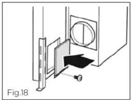
- Replace the cover of the terminal box Fig.18.
natural_image
Diagram showing a mechanical assembly with a central circular component and a black arrow pointing to a component, labeled Fig.18 (no text or symbols on the diagram itself)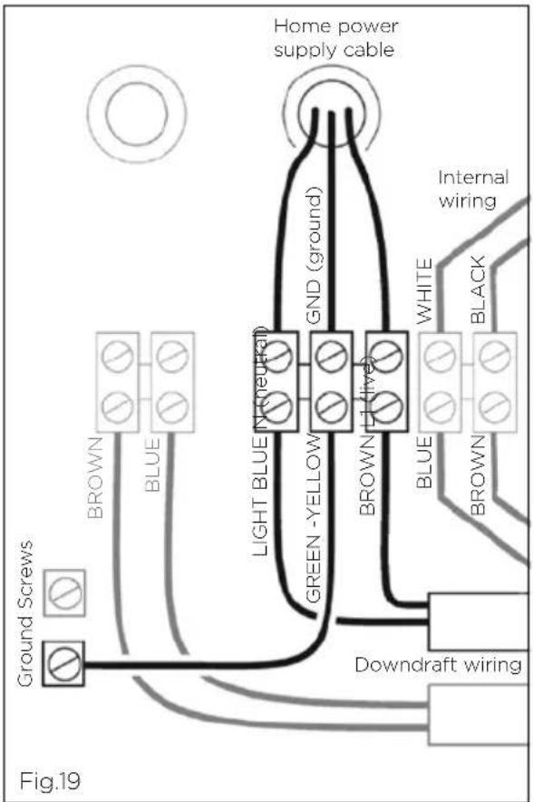
Downdraft unit remote blower electrical connection
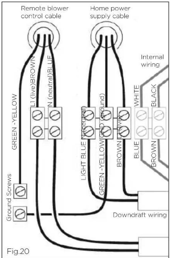
- Connect the power supply cable into the box as described in the 'Downdraft unit internal blower electrical connection' section (above).
- To use a remote blower, install a control cable between the downdraft unit and the remote blower. See the 'Remote blower electrical connection' on next page.
• Additional knock outs should be used for the remote blower wiring.
• Install a suitable UL listed strain relief or conduit fitting (not included) into the knock out. - Connect the remote blower wiring into the downdraft unit: N (neutral) into the right terminal, L1 (live) into the left terminal and the green (ground) wire goes into the ground terminal Fig.20.
- Ensure that the terminal screws are tightly holding all wires in place.
• The remote blower will be connected to the additional control cable - Replace the cover of the terminal box Fig.18.
Remote blower electrical connection
- Remove the cover from the remote blower, then remove the wiring box cover.
- Pull the electrical wiring through the hole in the blower base and secure it according to local codes using a suitable UL listed strain relief or conduit fitting (not included).
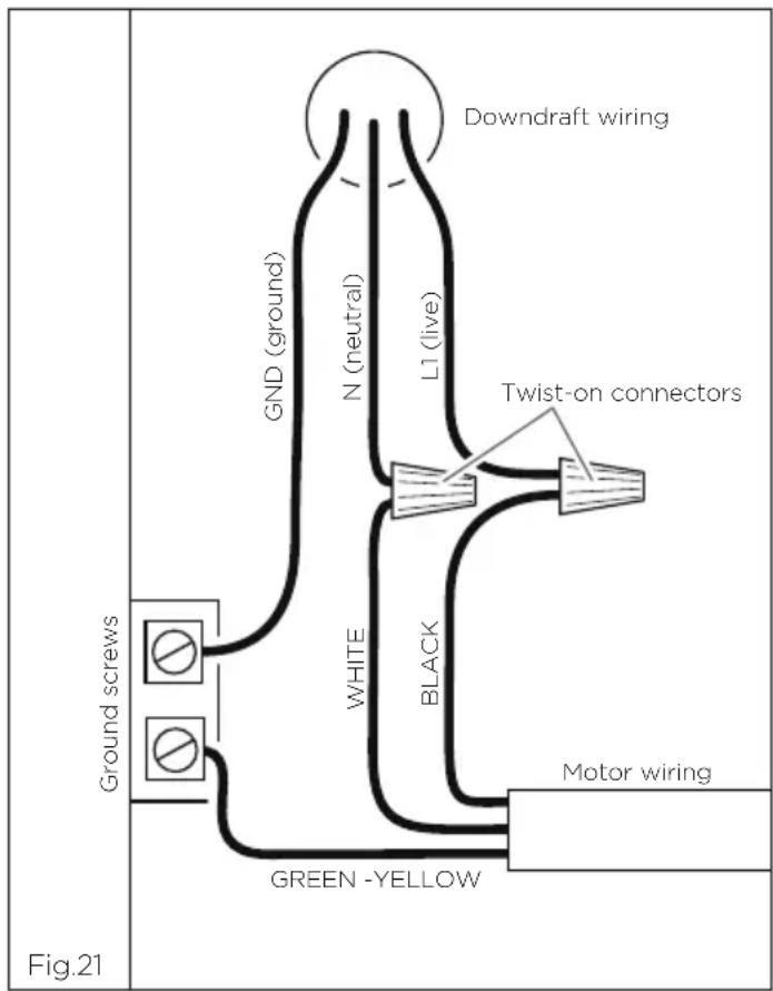
- ConnecttheN (neutral) wire to the white wire in the wiring box with twist-on connector Fig.21.
- ConnecttheL1 (live) wire to the black wire in the wiring box with twist-on connector Fig.21.
- Connect the green power supply ground wire to the green ground screw.
Attention - verify that the main filter, flap and wiring box cover are positioned correctly with wiring clearance.
- Replace the wiring box cover and screws taking care not to pinch the wiring under the wiring box cover.
- Reinstall the remote blower cover.
INSTALLATION INSTRUCTIONS
⑧ Complete the installation
- Place the top trim onto the downdraft unit.
- Push the power button on the top trim, the downdraft unit will rise. (The blower will begin to vent immediately if the blower control slider is set to an 'On' position).
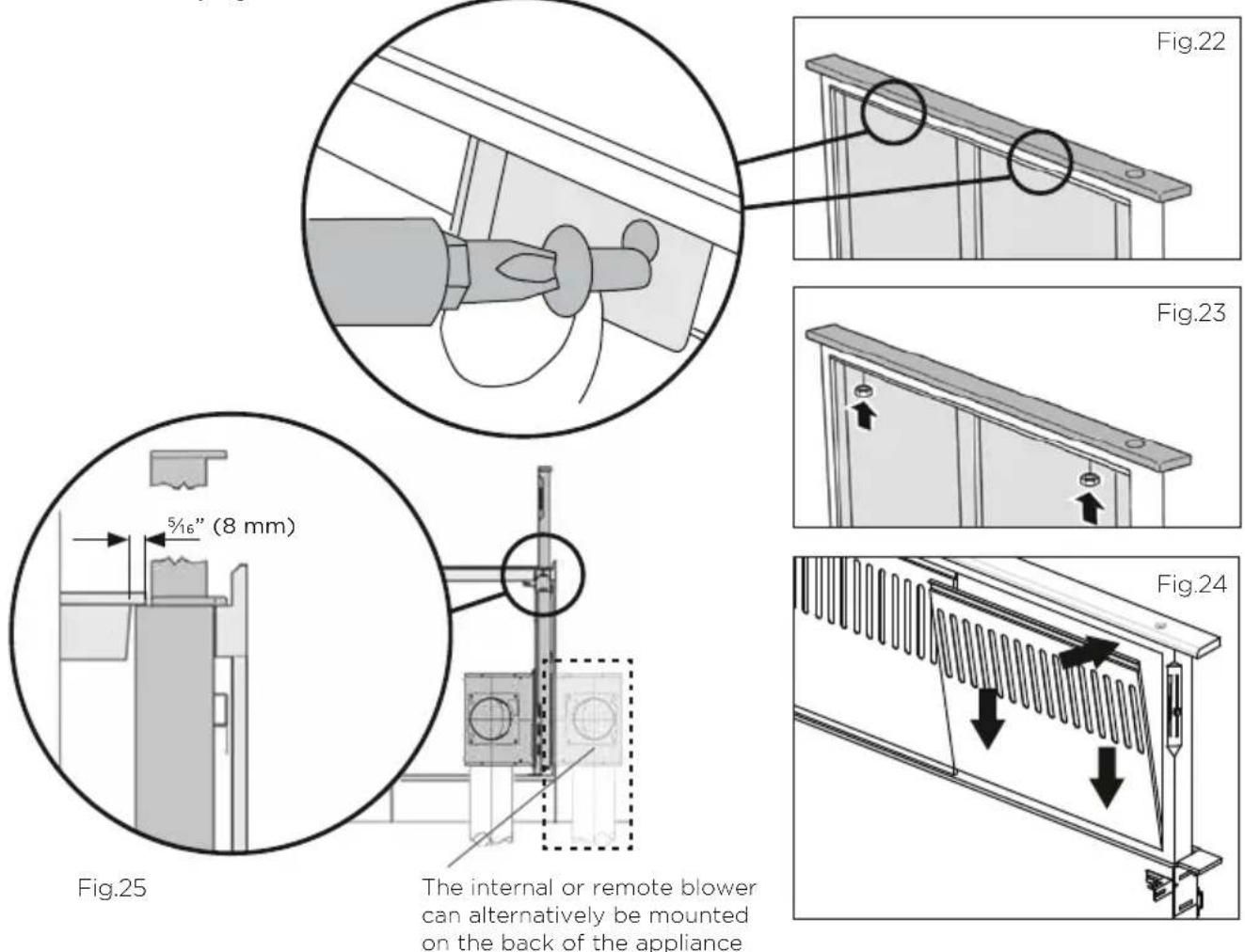
- Remove the labels, screw and brackets as shown in Fig.22. These brackets are used to hold the grease filter microswitches in place during transportation. They are located at the top of the downdraft unit in the centre behind each grease filter.
- Connect the top trim to the downdraft unit by threading the 932 " (7 mm) nuts onto the top trim screws Fig.23.
• Install the grease filters Fig.24. - Check the blower operation. If the blower does not work refer to the 'Troubleshooting' section on page 27.
⑨ Attach the ducting
- For the internal blower box, use 6" (152 mm) round ducting and the 6" (152 mm) diameter back draft damper.
- For the remote blower, use 10" (254 mm) round ducting.
- Attach ducting using clamps or aluminum duct tape to seal all joints and vent outside.
⑩ Remove packaging
- Remove all packaging and protective wrappings.
⑪ Install the cooktop
- Install the cooktop according to the manufacturer's instructions.
- Check to make sure that the rear edge of the cooktop overlaps the front edge of the downdraft unit by 516 (8 mm) Fig.25.
The downdraft vent system is designed to remove smoke, cooking vapors and odors from the cooktop area. For best results, the downdraft vent system should be operating before cooking is started and should continue to operate for several minutes after cooking is complete. If using large pots, place them on the rear burner to ensure proper ventilation, a higher fan setting may be required.
The flame sensing ignition on some gas cooktops may be affected by the downdraft by dispersing the flame away from the spark igniter. This may cause the spark to keep running while trying to reignite the burner that is already lit. To resolve this, and improve burner performance, decrease the fan speed or increase the burner setting, or both.
Controls

natural_image
Isometric technical diagram of a structural panel with labeled components A and B, showing internal compartments and mounting base (no text or symbols beyond labels)CONTROL PANEL FEATURES
| A | Power On/Off Push the power button on the top trim, the downdraft unit will rise. The blower will begin to vent immediately if the blower control slider is set to an ‘On’ position.Push the power button on the top trim, the blower will turn off and the downdraft unit will lower to the closed position. |
| B | Blower speed Slide the control slider on the right-hand side of the downdraft unit to adjust the blower motor speed. |
WARNING!
Unplug or disconnect the appliance from the power supply before servicing or cleaning.
IMPORTANT!
• Never use abrasive or oil based cleaners.
- Wear gloves to protect against sharp edges.
Maintenance
The downdraft vent system should be cleaned regularly using a mild, liquid detergent and a clean soft cloth to avoid a build-up of grease occurring. Avoid the use of corrosive chemicals, abrasive cleaning products, hard brushes and steel wool pads. Grease deposits are corrosive which can cause damage to your downdraft vent system.
Note: in areas of high humidity or coastal environments, cleaning should be carried out more frequently.
Grease filters
- Depending on use, and at least once a month, the aluminum grease filters should be removed and cleaned with hot soapy water or in a dishwasher. Please note that contact with other items in the dishwasher may cause surface scratching.
- If washed in a dishwasher, the filter should be placed in an upright position to prevent food from falling on them.
• After cleaning and drying, refit the filters.
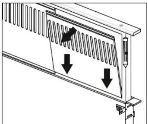
Removing the grease filters:
① Place fingertips in the groove at the top for the filters.
② Press down on the filters far enough for the tab at the top of the filters to clear.
③ Pull forward to release the filter from its groove.
④ Reverse these instructions when refitting the filters.
natural_image
Technical diagram of a ventilation duct system with directional arrows indicating airflow or movement (no text or symbols present)Remote blower
Disconnect the power supply and lock out the service panel before cleaning or servicing. To clean, remove the cover and vacuum the blower and housing, being careful not to damage the blower impeller. The motor is permanently lubricated, do not oil or disassemble.
Spills
IMPORTANT!
If a spill occurs on the cooktop that allows liquids to seep inside the downdraft unit, you must turn the downdraft vent system off immediately. It is possible to cause damage to the downdraft unit if water is allowed inside the downdraft unit while it is operating.
- Immediately turn off the downdraft vent system at the speed control located on the right-hand side of the downdraft unit.
- Turn off the power supply to the downdraft vent system at the circuit breaker box or fuse box.
- Allow plenty of time for the downdraft unit to dry naturally. Do not open the downdraft unit to remove the water.
If the downdraft vent system does not operate
- Check that a circuit breaker has not tripped or a household fuse blown.
- Check that the grease filters are properly installed.
- Check the downdraft unit fuse located under the power board.
Note: this downdraft unit is designed with a microswitch behind the center of each grease filter. These microswitches prevent the blower and the unit-raising and lowering mechanism from operating when either of the grease filters is removed. It is very important to make sure that the grease filters are properly and firmly in place. If the unit does not operate after replacing the grease filters, make sure the filters are properly installed and are making firm contact with the microswitches.
Safety switch
A safety switch, which stops the downdraft unit from rising up for safety reasons, will also stop the rise if it moves into the locked or “activated” position during shipment. By applying a simple turn with pliers on the main lifting screw the downdraft unit will rise by few millimeters releasing the safety switch.
If this does not work, these steps will put the safety switch in the "deactivated" or unlocked position to complete the installation.
Please perform these steps before proceeding with normal installation:
① Temporarily connect the power by following the 'Electrical connection' instruction on page 21.
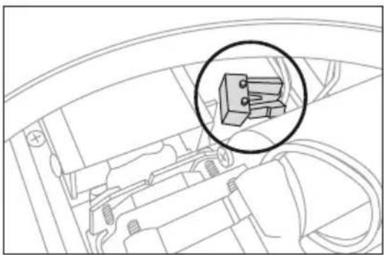
② Locate the safety switch by looking through the hole in the 10" (254 mm) remote blower connection plate on the front of the downdraft unit. This switch is the front switch in the pair of switches on the bottom of the downdraft unit, in front of lower limit switch (Fig.26).
③ Press and hold the power button (with a pointy object) on the top right of the downdraft unit Fig.27.
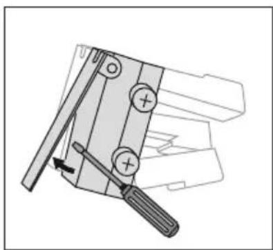
④ While holding the power button, place a small flat head screwdriver underneath the safety switch to disengage the lever from the safety switch button Fig.28. By pulling this lever away from the depressed safety switch button, this will return the downdraft unit to normal operation and the downdraft unit will now raise and lower normally.
⑤ Test the downdraft unit by pressing the power button on top of the downdraft unit for several raise and lower cycles to ensure the downdraft unit is operating without holding the safety switch.
⑥ Disconnect the power and proceed with the rest of the steps to install the product per the installation instructions on page 14.
These steps should only be required once and the safety switch will operate normally from then on.
natural_image
Interior view of a car dashboard with a highlighted component (no text or symbols visible)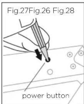

natural_image
Technical line drawing of a mechanical clamp or bracket assembly with a screwdriver and circular components (no text or symbols)| ITEM REFERENCE NUMBER | |
| Internal blower HBD600I | |
| Remote blower model HBD1200E | |
| Filter HD30 290317 | |
| Filter HD36 290334 |
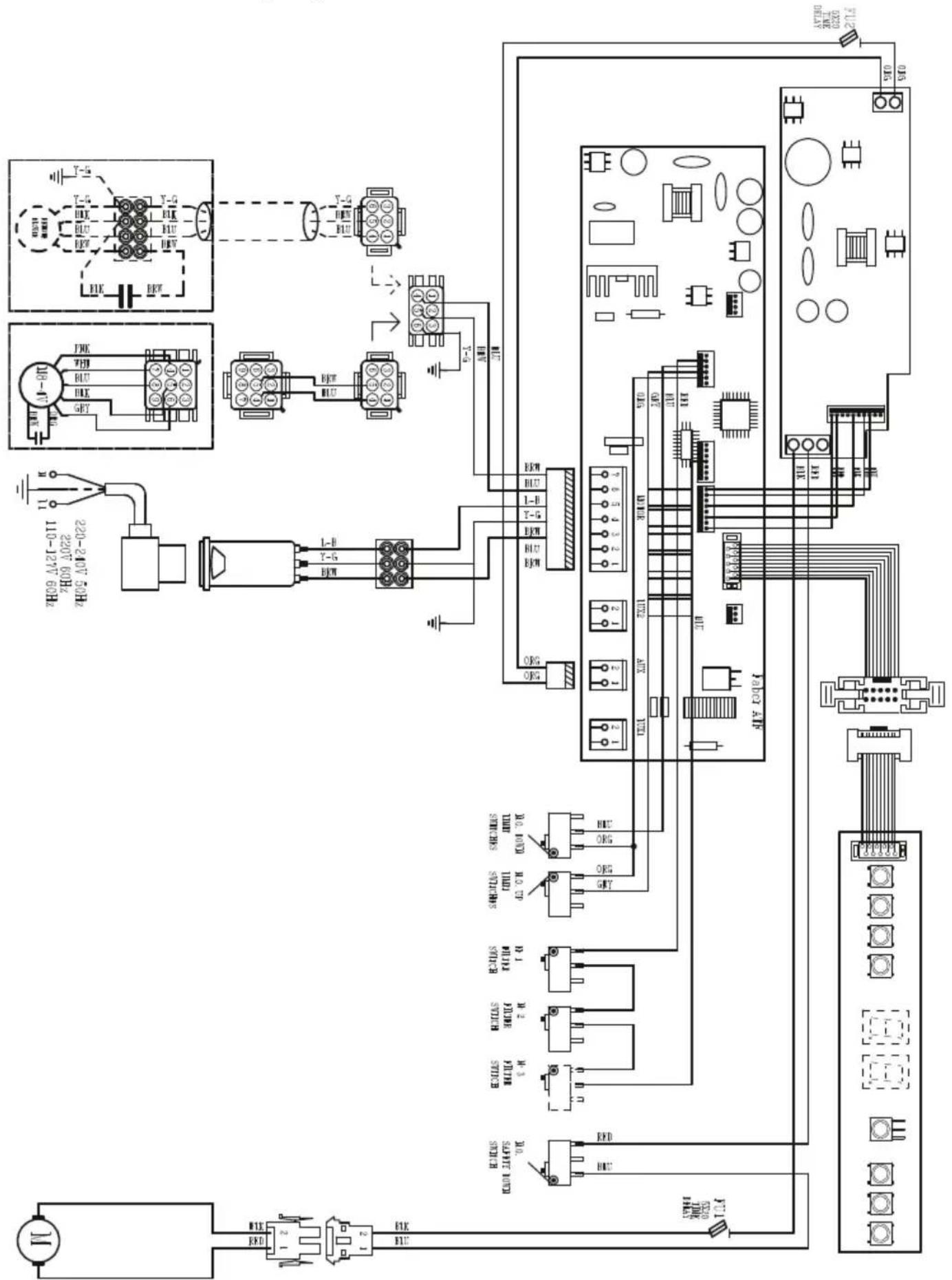
Downdraft unit wiring diagram
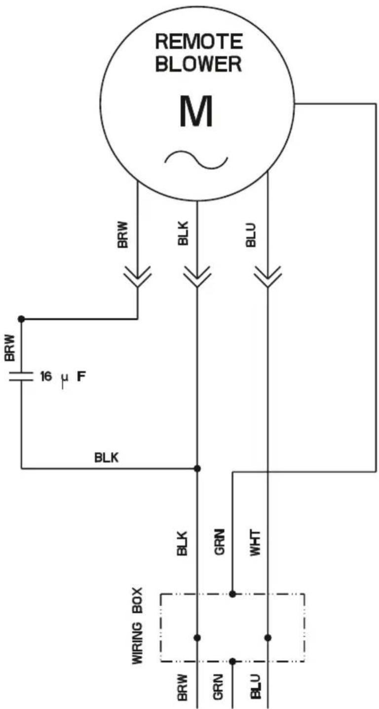
Remote blower wiring diagram
When you purchase any new Fisher & Paykel ventilation product for personal or consumer use you automatically receive a two year limited warranty covering parts and labor for servicing within the 48 mainland United States, Hawaii, Washington DC and Canada. In Alaska the limited warranty is the same except that you must pay to ship the product to the service shop or the service technician's travel to your home. Products for use in Canada must be purchased through the Canadian distribution channel to ensure regulatory compliance.
If the product is installed in a motor vehicle, boat or similar mobile facility, you receive the same two year limited warranty, but you must bring the vehicle, boat or mobile facility containing the product to the service shop at your expense or pay the service technician's travel to the location of the product.
There is no warranty for commercial purchase or use.
Fisher & Paykel undertakes to:
Repair without cost, with limited exceptions described herein, to the owner either for material or labor any part of the product, the serial number of which appears on the product, which is found to be defective during the term of the two year limited warranty.
In Alaska, you must pay to ship the product to the service shop or for the service technician's travel to your home. If the product is installed in a motor vehicle, boat or similar mobile facility, you must bring it to the service shop at your expense or pay for the service technician's travel to the location of the product. If we are unable to repair a defective part of the product after a reasonable number of attempts, at our option we may replace the part or the product, or we may provide you a full refund of the purchase price of the product (not including installation or other charges).
This warranty extends to the original purchaser and any succeeding owner of the product during the term of the warranty for products purchased for ordinary single-family home use.
All service under this limited warranty shall be provided by Fisher & Paykel or its Authorized Service Agent during normal business hours.
How long does this limited warranty last?
Our liability under the two year limited warranty expires two years from the date of purchase of the product by the first consumer.
Our liability under any implied warranties, including the implied warranty of merchantability (an unwritten warranty that the product is fit for ordinary use) expires two years (or such longer period as required by applicable law) from the date of purchase of the product by the first consumer. Some States do not allow limitations on how long an implied warranty lasts, so this limit on implied warranties may not apply to you. Fisher & Paykel will honor any warranty required by the law of the particular country or state in which the product is sold.
This limited warranty does not cover:
A Service calls that are not related to any defect in the product. The cost of a service call will be charged if the problem is not found to be a defect of the product.
For example:
① Correcting faulty installation of the product.
② Instructing you how to use the product.
③ Replacing house fuses, resetting circuit breakers, correcting house wiring or plumbing, or replacing light bulbs.
④ Correcting fault(s) caused by the user.
⑤ Changing the set-up of the product.
⑥ Unauthorized modifications of the product.
⑦ Noise or vibration that is considered normal, for example, fan sounds/noises or user warning beeps.
⑧ Correcting damage caused by pests, for example, rats, cockroaches, etc.
B Defects caused by factors other than:
① Normal domestic use or
② Use in accordance with the product's user guide.
© Defects to the product caused by accident, neglect, misuse, fire, flood or 'act of God'.
D The cost of repairs carried out by non-authorized repairers or the cost of correcting such unauthorized repairs.
E Travel fees and associated charges incurred when the product is installed in a location with limited or restricted access (eg airplane flights, ferry charges, isolated geographic areas).
⑤ Normal recommended maintenance as set out in the product's user guide.
⑥ Filter replacement except in the case of faulty parts or materials within the filter cartridge.
⑧ Damage (including water damage) caused by faulty installation, plumbing or wiring.
This product has been designed for use in a normal domestic (residential) environment. This product is not designed for commercial use (whatsoever). Any commercial use by a customer will terminate this product's limited warranty.
If you have an installation problem contact your dealer or installer. You are responsible for providing adequate electrical, exhausting and other connection facilities.
Fisher & Paykel will not be responsible for consequential or incidental damages (including, without limitation, the cost of repairing or replacing other property damaged if the product is defective or any of your expenses caused if the product is defective). Some States do not allow the exclusion or limitation of incidental or consequential damages, so the above limitation or exclusion may not apply to you.
How to get service
Please read your user guide. If you then have any questions about operating the product, need the name of your local Fisher & Paykel Authorized Service Agent, or believe the product is defective and wish service under this limited warranty, please contact your dealer or call us at:
USA and Canada
TOLL FREE 1.888.9.FNP.USA (1.888.936.7872)
or use the link at: www.fisherpaykel.com/locator/servicer/
You may be required to provide reasonable proof of the date of purchase of the product before the product will be serviced under this limited warranty.
No other warranties
This limited warranty is the complete and exclusive agreement between you and Fisher & Paykel regarding any defect in the product and no other express warranty has been made or will be made on behalf of Fisher & Paykel. None of our employees (or our Authorized Service Agents) are authorized to make any addition or modification to this limited warranty.
Warrantor: Fisher & Paykel Appliances, Inc.
If you need further help concerning this limited warranty, or need to make a claim under this warranty, please call us at the above number, or write to:
Fisher & Paykel Appliances, Inc.
695 Town Center Drive, Suite 180
Costa Mesa
CA 92626
This limited warranty gives you specific legal rights, and you may also have other rights which vary from country to country and from state to state.
Complete and keep for safe reference:
Model
Serial No. ____
Purchase Date ____
Purchaser ____
Dealer
Suburb
Town ____
Country ____
Introduction 39
natural_image
Technical line drawing of a mechanical assembly with ventilation grilles and mounting base (no text or symbols)MISE EN GARDE!

35 lb (16 kg)
(HC30)
44 lb (20 kg)
(HC36)
11 lb (5 kg)
(HBD600I)
33 lb (15 kg)
(HBD1200E)
National Fire Protection Association
Batterymarch Park
Quincy, Massachusetts 02269
natural_image
Isometric line drawing of a rectangular device with two internal compartments and a top panel (no text or symbols)natural_image
Simple line drawing of a long rectangular object with a small protrusion at the end (no text or symbols)Garniture supérieure (1)
natural_image
Simple line drawing of a rectangular panel with vertical slots, no text or symbols presentnatural_image
Simple line drawing of a 3D rectangular box with a circular opening on top (no text or symbols)natural_image
Exterior view of a rectangular electronic enclosure with grid-patterned panel (no text or symbols)natural_image
Technical line drawing of a mechanical ring or bearing assembly (no text or symbols)

natural_image
Technical line drawing of a mechanical assembly with no visible text or symbols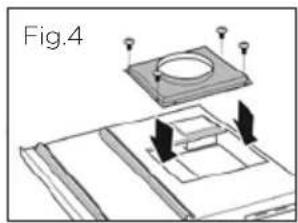
INSTRUCTIONS D'INSTALLATION

natural_image
Diagram of a washing machine with internal components and wiring, showing no text or symbols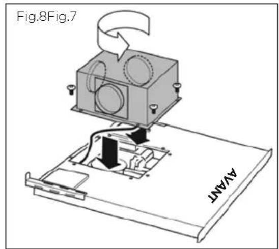

natural_image
Technical illustration showing a bolt assembly process with a magnified view of the component (no text or symbols present)natural_image
Technical diagram showing mechanical assembly with magnified detail (no text or symbols)National Fire Protection Association
Battery March Park
Quincy, Massachusetts 02269
natural_image
Diagram showing a mechanical assembly with a central circular component and directional arrow, labeled Fig.18 (no text or symbols on the diagram itself)
natural_image
Technical line drawing of a structural panel with labeled components A and B, showing internal structure and mounting base (no text or symbols beyond labels)FONCTIONNALITÉS DU PANNEAU DE COMMANDE
natural_image
Technical diagram of a ventilation duct system with downward arrows indicating airflow or pressure direction (no text or symbols present)natural_image
Interior view of a car dashboard with a highlighted component (no text or symbols visible)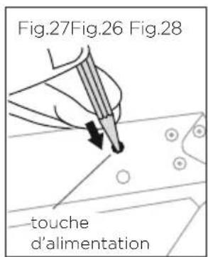
natural_image
Mechanical assembly diagram showing a tool inserted into a bracket with circular components and a pointer (no text or labels)Fisher & Paykel Appliances, Inc.
695 Town Center Drive, Suite 180
Costa Mesa
CA 92626
© Fisher & Paykel Appliances 2018. All rights reserved. The product specifications in this booklet apply to the specific products and models described at the date of issue. Under our policy of continuous product improvement, these specifications may change at any time. You should therefore check with your Dealer to ensure this booklet correctly describes the product currently available.
- SYSTÈME DE VENTILATION TÉLESCOPIQUE À ASPIRATION DESCENDANTE
- IMPORTANT!
- SAVE THESE INSTRUCTIONS
- Registration
- ! WARNING!
- WARNING!
- IMPORTANT SAFETY INSTRUCTIONS
- READ AND SAVE THESE INSTRUCTIONS
- CAUTION!
- Cold weather installations (not included)
- INSTALLATION INSTRUCTIONS
- Downdraft unit contents of packaging
- Internal blower (HBD600I) contents of packaging
- Remote blower (HBD1200E) contents of packaging
- Cabinet cutout dimensions
- Compatible blowers with the downdraft vent system
- Compatible cooktops with the downdraft vent system
- Venting requirements
- Plan the ductwork
- Calculate the duct run length
- ② Prepare the downdraft unit for the intended blower
- Internal blower
- Remote blower
- ③ Temporarily insert the downdraft into the cabinet
- ④ Remove the downdraft from the cabinet
- ⑤ Install the internal or remote blower
- Internal blower installation in one of the following three options:
- Option 1: Internal blower, front installation for venting left, right or down
- Option 2: Internal blower, back installation for venting left, right or down
- Remote blower installation in one of the following three options:
- Option 1: Wall installation
- Option 2: Sloped roof installation
- Option 3: Flat roof installation
- ⑥ Prepare for electrical connection
- Downdraft unit
- Electrical requirements
- Downdraft unit internal blower electrical connection
- Downdraft unit remote blower electrical connection
- Remote blower electrical connection
- Attention - verify that the main filter, flap and wiring box cover are positioned correctly with wiring clearance.
- ⑧ Complete the installation
- ⑨ Attach the ducting
- ⑩ Remove packaging
- ⑪ Install the cooktop
- Maintenance
- Grease filters
- Removing the grease filters:
- Spills
- Safety switch
- Please perform these steps before proceeding with normal installation:
- Fisher & Paykel undertakes to:
- How long does this limited warranty last?
- This limited warranty does not cover:
- How to get service
- USA and Canada
- No other warranties
- MISE EN GARDE!
- INSTRUCTIONS D'INSTALLATION
Brand : Fisher & Paykel
Model : HD30
Category : Fan