CBG6251WP - Basket CANDY - Free user manual and instructions
Find the device manual for free CBG6251WP CANDY in PDF.
| Product type | Built-in extractor hood |
| Brand | Candy |
| Model | CBG6251WP |
| Cutout dimensions (W x D) | 490 x 250 mm |
| Power supply | 220-240 V ~ 50 Hz |
| Electrical class | Class I (earthing required) |
| Number of speeds | 3 (low, medium, high) |
| Control type | Push buttons |
| Lighting | Integrated LED lamp (2 W max) |
| Grease filter type | Non-stick aluminium, washable |
| Activated carbon filter | Optional, annual replacement |
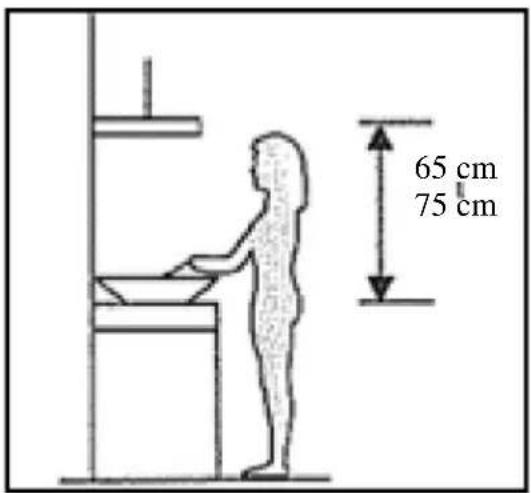
| Safety distance above cooktop | 65 - 75 cm |
| Exhaust duct diameter | 150 mm |
| Mounting type | Built-in under cabinet |
| Grease filter cleaning frequency | Monthly |
| Bulb replacement | LED of same type (220 V, 2 W max) |
| Material | Stainless steel (surface) |
| Color | White |
| Environmental compliance | WEEE Directive 2012/19/EU |
| Country of manufacture | Not specified in the manual |
Frequently Asked Questions - CBG6251WP CANDY
User questions about CBG6251WP CANDY
0 question about this device. Answer the ones you know or ask your own.
Ask a new question about this device
Download the instructions for your Basket in PDF format for free! Find your manual CBG6251WP - CANDY and take your electronic device back in hand. On this page are published all the documents necessary for the use of your device. CBG6251WP by CANDY.
USER MANUAL CBG6251WP CANDY
INSTALLATION AND USER'S MANUAL
CONTENT
INTRODUCTION....3
SAFETYPRECAUTION....3-4
PREPARE FOR INSTALLATION......6
SKPECIFICATIONS....7
INSTALLATION....7-8
OPERATION....9
MAINTENANCE.... 10
TROUBLESHOOTING....11
ENVIRONMENTALPROTECTION....11
INTRODUCTION
Thank you for choosing this cooker hood.
This instruction manual is designed to provide you with all required Instructions related to the installation, use and maintenance of the appliance.
In order to operate the unit correctly and safety, please read this instruction manual carefully before installation and usage.
The cooker hood use high quality materials, and is made with a streamlined design. Equipped with large power electric motor and centrifugal fan, it also provides strong suction power, low noise operation, non-stick grease filter and easy assembly installation.
SAFETY PRECAUTION
- Never let the children operate the machine.
- The cooker hood is for home use only, not suitable for barbecue, roast shop and other commercial purpose.
- The cooker hood and its filter should be clean regularly in order to keep in good working condition.
- Clean the cooker hood according to the instruction manual and keep the unit from danger of burning. There is a fire risk if cleaning is not carried out in accordance with the instructions.
- Forbid the direct baking from the gas cooker.
- Please keep the kitchen room a good convection.
- If the supply cord is damaged, it must be replaced by the manufacturer, its service agent similarly qualified persons in order to avoid a hazard.
-
There shall be adequate ventilation of the room when the range hoods used at the same time as appliances burning gas or other fuels;
-
The air must not be discharged into a flue that is used for exhausting fumes from appliances burning gas or other fuels;
- Regulations concerning the discharge of air have to be fulfilled.
- This appliance can be used by children aged from 8 years and above and persons with reduced physical, sensory or mental capabilities or lack of experience and knowledge if they have been given supervision or instruction concerning use of the appliance in a safe way and understand the hazards involved.
- Children should be supervised to ensure that they do not play with the appliance.
- Cleaning and user maintenance shall not be made by children without supervision.
- Do not flame under the range hood.
- CAUTION: Accessible parts may become hot when used with cooking appliance.
- The warning shall be in the same part of the instructions that include details of how to mount the equipment.
Electrical Shock Hazard
- Only plug this unit into a properly earthed outlet. If in doubt seek advice from a suitably qualified engineer.
- Failure to follow these instructions can result in death, fire, or electrical shock.
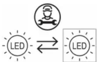
flowchart
graph LR
    A["LED"] <--> B["LED"]
The lamp used in this product is not suitable for use in the lighting of a room.
The purpose of this lamp is to provide illumination for using the product.
Electrical Installation
All installation must be carried out by a competent person or qualified electrician. Before connecting the mains supply ensure that the mains voltage corresponds to the voltage on the rating plate.
Direct Connection
The appliance must be connected directly to the mains using an omnipolar circuit breaker with a minimum opening of 3mm between the contacts.
The installer must ensure that the correct electrical connection has been made and that it complies with the wiring diagram.
The cable must not be bent or compressed.
Regularly check the power plug and power cord for damage. If the supply cord is damaged, it must be replaced by a special cord or assembly available from the manufacturer or its service agent.
WARNING: This is a Class I appliance and MUST be earthed
This appliance is supplied with a 3 core mains cable coloured as follows:
Brown = L or Live
Blue = N or Neutral
Green and Yellow = E or Earth
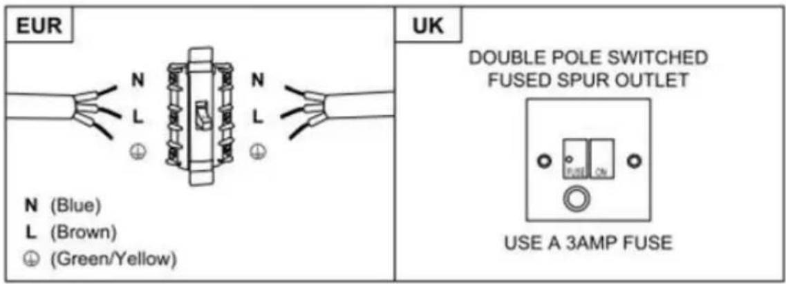
The fuse must be rated at 3 Amps.
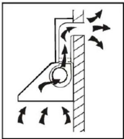
Prepare for installation:
a. If you have an outlet to the outside, your cooker hood can be connected as below picture by means of an extraction duct (enamel, aluminum, flexible pipe or inflammable material with an interior diameter of 150mm)
natural_image
Diagram of a mechanical or fluidic system with directional arrows indicating flow or movement (no text or symbols present)b. Before installation, turn the unit off and unplug it from the outlet.
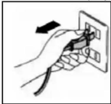
natural_image
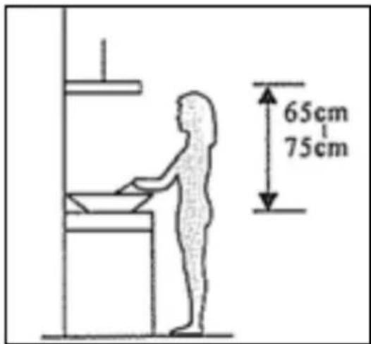
Hand holding a plug inserted into an electrical outlet socket (no text or symbols visible)c. The cooker hood should be placed at a distance of 65\~75cm above the cooking plane for best effect.
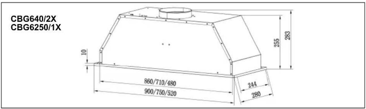
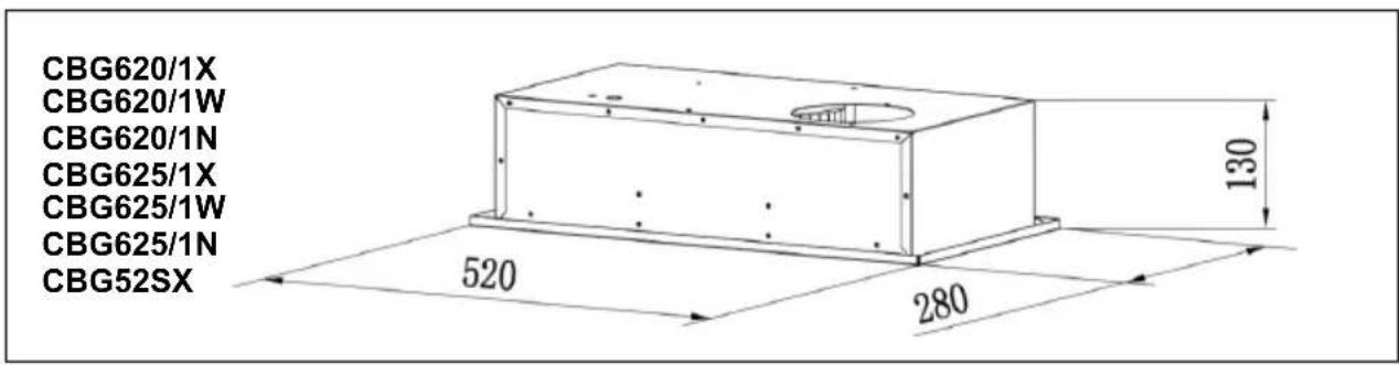
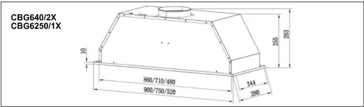
Specifications

Installation
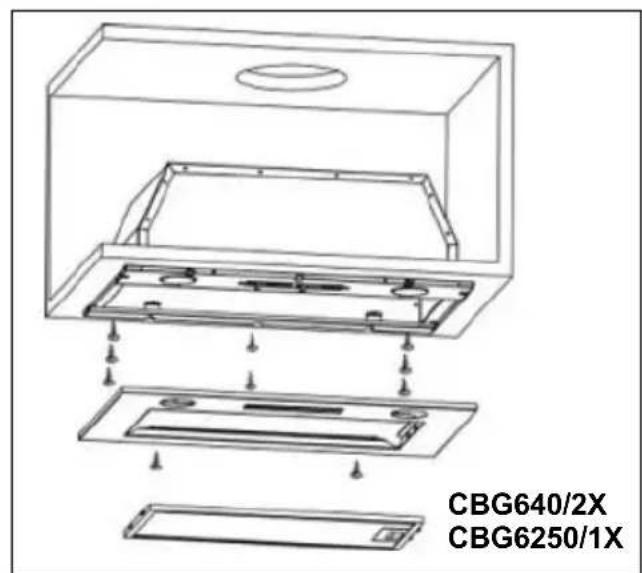
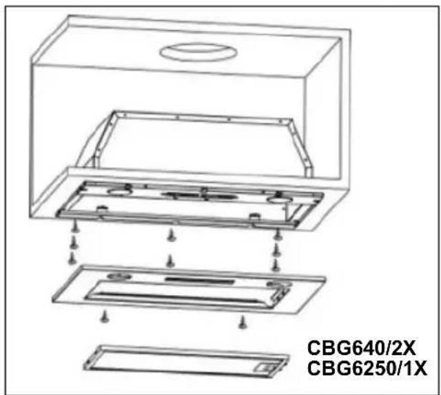
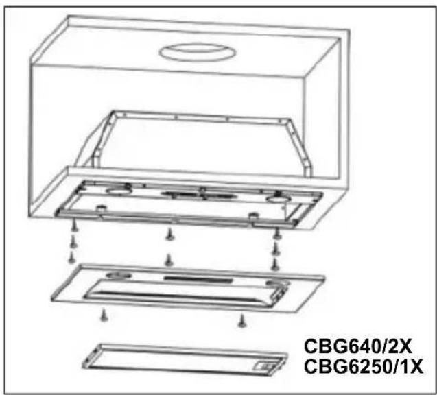
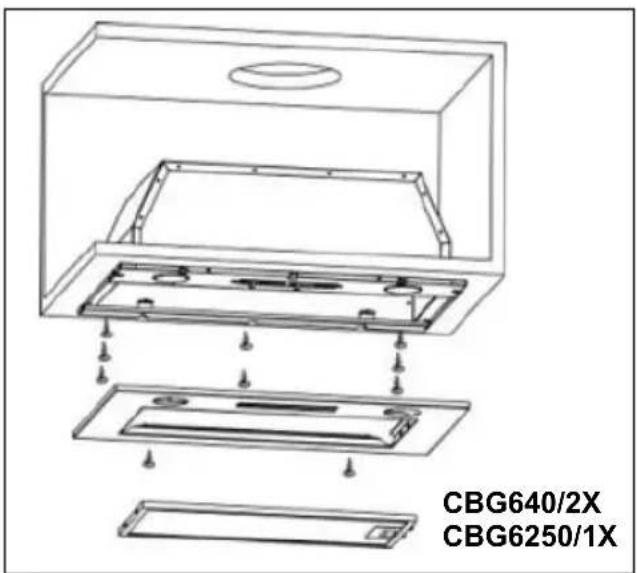
- The typical installation method for your range hood is into a purpose built overhead/wall cabinet.
- Using a jigsaw, create the required cut-out for your range hood, as 490 × 250mm
- Make sure the cut-out is at least 35mm from the cabinet edge.
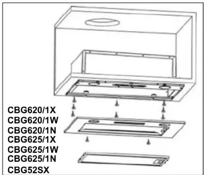
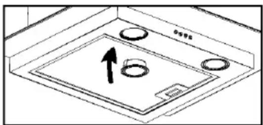
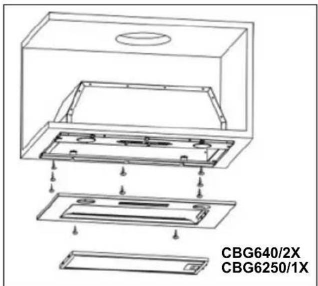
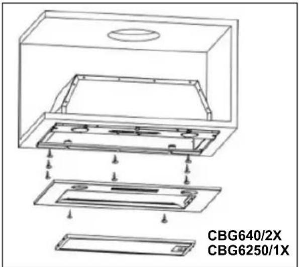
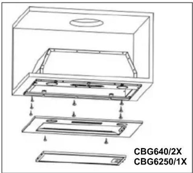
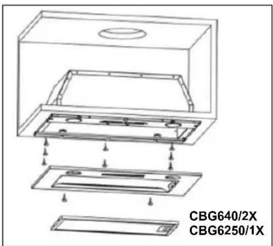
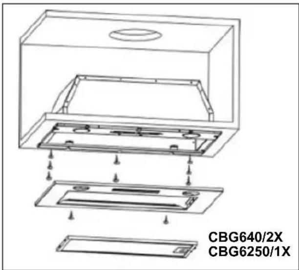
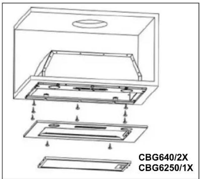
- Remove the grease filter and remove the 2 screws on the panel.
- Screw the range hood into the cabinet using 8 screws (supplied).
- Re-fit the panel with the 2 screws (previously removed).
Activated carbon filter can be used to trap odors.
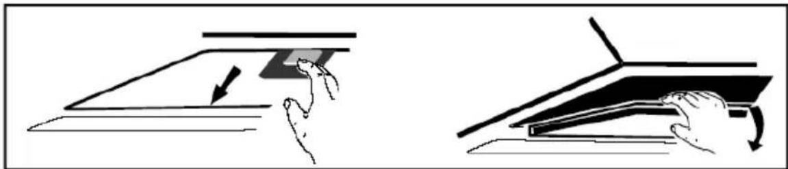
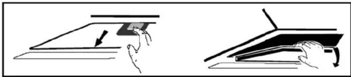
In order to install the activated carbon filter, the grease filter should be detached first. Press the lock and pull it downward.
natural_image
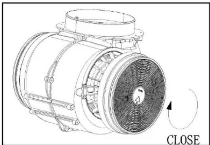
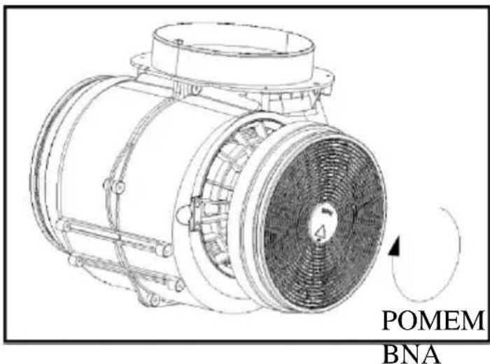
Two-step diagram showing hand pressing a component on a flat surface, with arrows indicating motion (no text or symbols)Plug the activated carbon filter into the unit and turn it in clockwise direction. Repeat the same on the other side.
natural_image
Technical line drawing of a mechanical fan or motor assembly with no visible text or symbolsNOTE:
○ Make sure the filter is securelylocked. Otherwise, it would loosen and cause dangerous.
- When activated carbon filter attached, the suction power will be lower.
DESCRIPTION OF COMPONENTS


OPERATION
Off button 0
It's used for turning off the fan.
Low Speed button

It's used for Ventilation on the kitchen. It is suitable for simmering and cooking which do not make much steam.
Medium Speed button

Airflow speed is ideally for ventilation in standard cooking operation.
High Speed button

When high density of smoke or steam produced, press high-speed button for highest effective ventilation.
NOTE: If Low / Medium / High speed buttons are press at the same time, the unit will only operate at the highest speed.
Light button

MAINTENANCE
Before cleaning switch the unit off and pull out the plug.
I. Regular Cleaning
Use a soft cloth moistened with hand-warm mildly soapy water or household cleaning detergent. Never use metal pads, chemical, abrasive material or stiff brush to clean the unit.
II. Monthly Cleaning for Grease Filter
ESSENTIAL: Clean the filter every month can prevent any risk of fire.
The filter collects grease, smoke and dust.....so the filter is directly affecting the efficiency of the cooker hood. If not cleaned, the grease residue (potential flammable) will saturate on the filter. Clean it with household cleaning detergent.
III. Annual Cleaning for Activated Carbon Filter
Apply SOLELY to unit that installed as a recirculation unit (not vented to the outside). This filter traps odours and must be replaced at least once a year depending on how frequent the cooker hood used.
III. Bulb Replacement
- Switch the unit off and unplug the appliance.
- Remove the lamp cover by unscrewing the 2 screws.
- Unscrew the LED lamp
- Replace with the same type and lamp
● LED lamp (220V max, 2W).
natural_image
Diagram of a kitchen sink with circular fixtures and an upward arrow indicating direction (no text or symbols)TROUBLESHOOTING
| Fault | Cause | Solution |
| Light on, but fan does not work | The fan blade is jammed. | Switch of the unit and repair by qualified service personnel only. |
| The motor is damaged. | ||
| Both light and fan do not work | light bulb burn. | Replace the bulb with correct rating. |
| Power cord looses. | Plug in to the power supply again. | |
| Serious Vibration of the unit | The fan blade is damaged. | Switch of the unit and repair by qualified service personnel only. |
| The fan motor is not fixed tightly. | Switch of the unit and repair by qualified service personnel only. | |
| The unit is not hung properly on the bracket. | Take down the unit and check whether the bracket is in proper location. | |
| Suction performance not good | Too long distance between the unit and the cooking plane | Readjust the distance to 65-75cm |
ENVIRONMENTAL PROTECTION
Waste electrical products should not be disposed of with household waste. Please recycle where facilities exist. Check with your Local Authority or retailer for recycling advice.
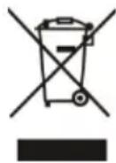
This appliance is marked according to the European directive 2012/19/EU on Waste Electrical and Electronic Equipment (WEEE).
By ensuring this product is disposed of correctly, you will help prevent potential negative consequences for the environment and human health, which could otherwise be caused by inappropriate waste handling of this product.
The symbol on the product indicates that this product may not be treated as household waste. Instead it shall be handed over to the applicable collection point for the recycling of electrical and electronic equipment
Disposal must be carried out in accordance with local environmental regulations for waste disposal.
For more detailed information about treatment, recovery and recycling of this product, please contact your local city office, your household waste disposal service or the shop where you purchased the product.
natural_image
Diagram of airflow around a mechanical structure with directional arrows indicating movement (no text or symbols)natural_image
Hand inserting a plug into an electrical outlet (no text or symbols visible)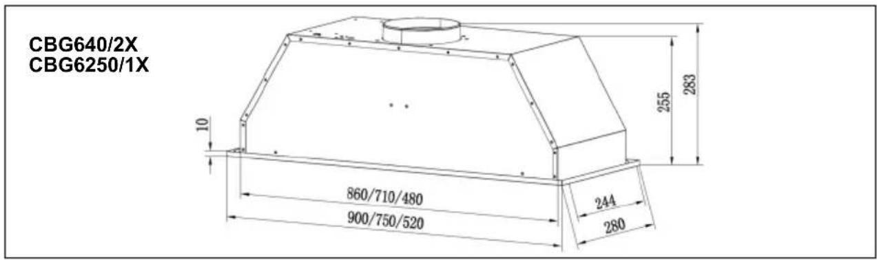
natural_image
Illustration showing two hand-drawn diagrams of a device with a scroll, one pointing at a component and the other holding a slide (no text or symbols)natural_image
Technical line drawing of a mechanical fan or motor assembly with no visible text or symbolsملاحظة:
natural_image
Diagram of a mechanical component with two circular holes and an upward arrow, no text or symbols presentnatural_image
Diagram of airflow around a mechanical component with directional arrows indicating movement (no text or symbols)natural_image
Hand inserting a plug into an electrical outlet (no text or symbols visible)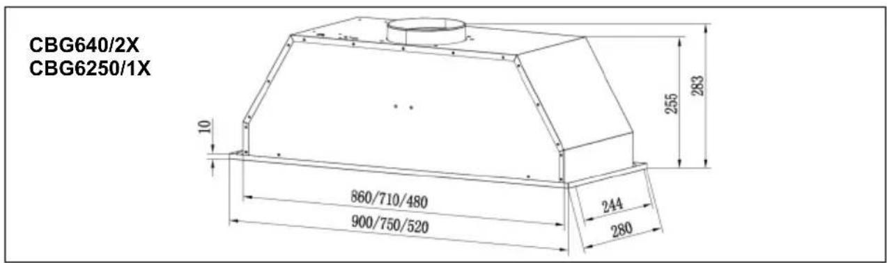
Instalace
natural_image
Two-step diagram showing hand positioning of a flat surface with an arrow indicating direction (no text or symbols)natural_image
Technical line drawing of a mechanical fan or motor assembly with no visible text or symbolsPOZNÁMKA:
natural_image
Isometric diagram of a mechanical component with two circular holes and an upward arrow, no text or symbols present.ŘEŠENÍ PROBLÉMŮ
INSTALLATION....38-39
BETRIEB....40
WARTUNG 41
FEHLERBEHEBUNG 42
UMWELTSCHUTZ 42
EINLEITUNG
Blau = N Oder Neutral
natural_image
Diagram of airflow around a mechanical structure with directional arrows indicating movement (no text or symbols)natural_image
Hand inserting a plug into an electrical outlet (no text or symbols visible)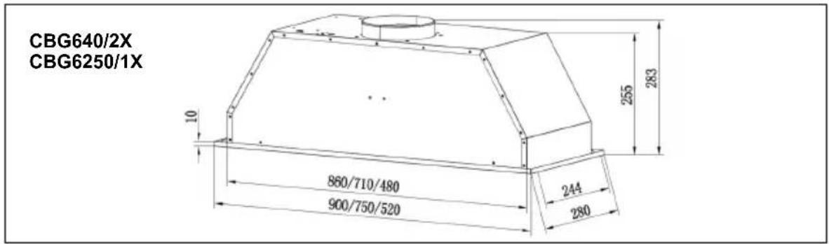
Installation

natural_image
Illustration showing two hand-drawn diagrams of a mechanical or architectural component, one with an arrow indicating direction and the other with a curved handle (no text or symbols)natural_image
Isometric diagram of a mechanical component with circular features and an upward arrow, no text or symbols presentFEHLERBEHEBUNG
The appliance must be connected directly to the mains using an omnipolar circuit breaker with a minimum opening of 3mm between the contacts.
The cable must not be bent or compressed.
natural_image
Diagram of airflow around a mechanical structure with directional arrows indicating movement (no text or symbols)natural_image
Hand inserting a plug into an electrical outlet (no text or symbols visible)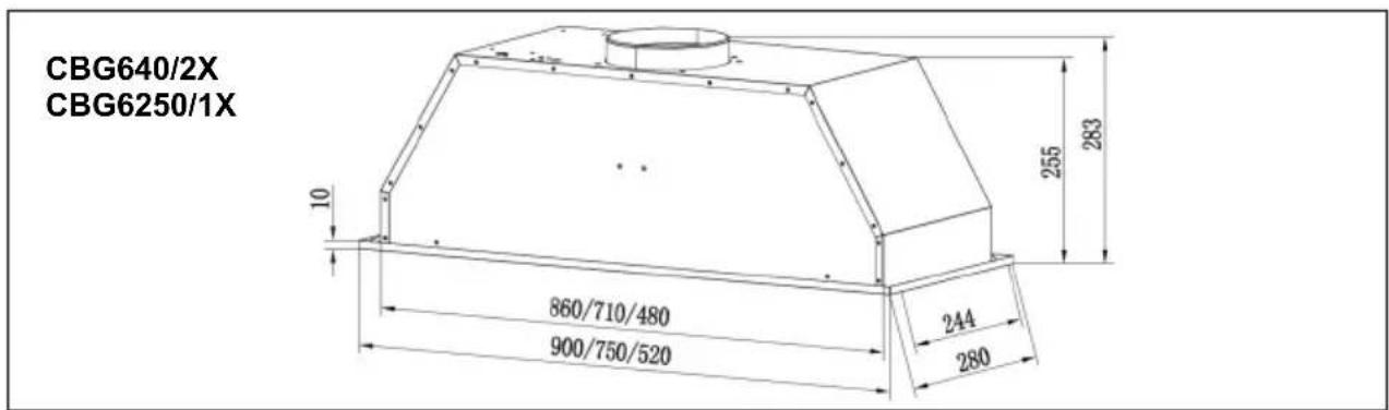
Installation
natural_image
Illustration showing two hand-drawn diagrams of a device with a handle, one pointing to a component and the other holding a slide (no text or symbols)natural_image
Technical line drawing of a mechanical fan or motor assembly with no visible text or symbolsREMARQUE :
natural_image
Diagram of a kitchen sink with two circular fixtures and an upward arrow indicating direction (no text or symbols)DÉPANNAGE
natural_image
Diagram of airflow around a mechanical structure with directional arrows indicating movement (no text or symbols)natural_image
Hand inserting a plug into an electrical outlet (no text or symbols visible)CBG620/1X
CBG620/1W
CBG620/1N
CBG625/1X
CBG625/1W
CBG625/1N
CBG52SX
CBG640/2X
CBG6250/1X
Installazione
natural_image
Illustration showing two hand-drawn diagrams of a device or tool, one with an arrow and the other with a handle (no text or symbols)natural_image
Technical line drawing of a mechanical fan or motor assembly with no visible text or symbolsNOTA:
natural_image
Technical diagram showing a mechanical component with two circular holes and an upward arrow, no text or symbols present.SOLUZIONE DEI PROBLEMI
Blauw = N of Neutrale
natural_image
Diagram of airflow around a mechanical component with directional arrows indicating movement (no text or symbols)natural_image
Hand inserting a plug into an electrical outlet (no text or symbols visible)
Installatie
natural_image
Two-step diagram showing hand positioning of a component on a flat surface, with no text or symbols present.natural_image
Technical line drawing of a SLUITEN electric motor with visible blades and mounting flanges (no text or symbols on the diagram itself)OPMERKING:
natural_image
Diagram of a kitchen sink with rings and a directional arrow, no text or symbols presentPROBLEMEN OPLOSSEN
natural_image
Diagram of airflow around a mechanical component with directional arrows indicating movement (no text or symbols)natural_image
Hand holding a wall socket with a cable, showing an electrical switch (no text or symbols visible)
Instalacja
natural_image
Two-step diagram showing hand positioning of a component on a flat surface, with no text or symbols present.natural_image
Diagram of a mechanical component with a central rotating ring and two circular holes, no text or symbols present.USUWANIE USTEREK
flowchart
graph LR
    A["LED"] --> B["Robot Icon"]
    B --> C["LED"]
natural_image
Diagram of airflow around a mechanical structure with directional arrows indicating movement (no text or symbols)natural_image
Hand holding a power outlet plug with a cable, no text or symbols visible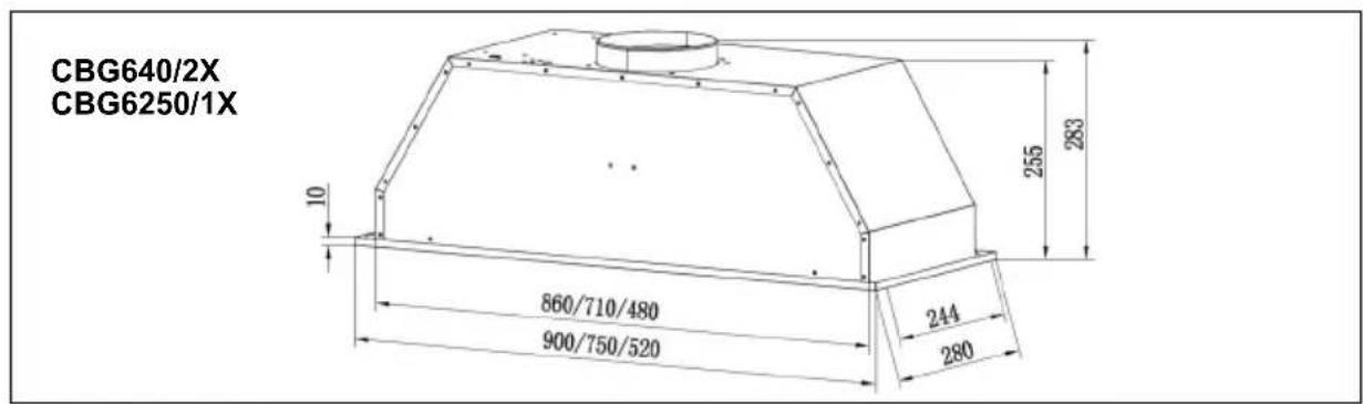
Установка
natural_image
Illustration showing two hand-drawn diagrams of a mechanical or architectural component, one with an arrow indicating direction and the other with a curved blade (no text or symbols)natural_image
Technical line drawing of a mechanical fan or motor assembly with no visible text or symbolsПРИМЕЧАНИЕ.
natural_image
Diagram of a kitchen sink with rings and a directional arrow, no text or symbols presentnatural_image
Diagram of airflow around a mechanical component with directional arrows indicating movement (no text or symbols)natural_image
Hand holding a power outlet plug with a cable, no text or symbols visible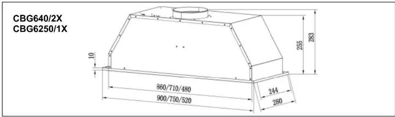
Inštalácia
Filter s aktivnym uhlím je možné použit' na zachytenie zápachu. Ak chcete nainštalovat' filter s aktivnym uhlím, najskôr by mal byt' odinštalovaný filter tuku. Stlačte zámok a potiahnite ho smerom nadol.
natural_image
Two-step diagram showing hand positioning of a component on a flat surface, with no text or symbols present.natural_image
Diagram of a mechanical component with circular holes and an upward arrow, no text or symbols presentRIEŠENIE PROBLÉMOV
natural_image
Diagram of airflow around a mechanical structure with directional arrows indicating movement (no text or symbols)natural_image
Hand inserting a plug into an electrical outlet (no text or symbols visible)c. Kuhinjsko napo za op timalno učinkovitost namestite 65-75 cm nad kuhalno površino.
Specifikacije
Namestitev
natural_image
Two-step diagram showing hand positioning of a flat surface with an arrow indicating direction (no text or symbols)Namestite filter z aktivnim ogljem v enoto in ga obrnite v smeri urnega kazalca. Enako ponovite na drugi strani.
OPOMBA:
natural_image
Diagram of a mechanical component with two circular holes and an upward arrow, no text or symbols presentODPRAVLJANJE NAPAK
natural_image
Diagram of airflow around a mechanical component with directional arrows indicating movement (no text or symbols)natural_image
Hand holding a power outlet plug with a black arrow indicating left motion (no text or symbols)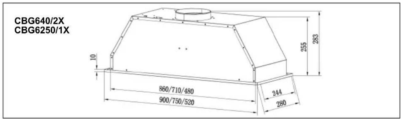
Instalação

natural_image
Illustration showing two hand-drawn steps of a mechanical or architectural component, one with an arrow indicating direction and the other with a curved handle (no text or symbols)natural_image
Technical line drawing of an electric motor with a circular arrow indicating rotation (no text or symbols on the diagram itself)AR
NOTA:
natural_image
Isometric diagram of a square plate with circular holes and an upward arrow, no text or symbols presentnatural_image
Diagram of airflow around a mechanical structure with directional arrows indicating movement (no text or symbols)natural_image
Hand holding a power outlet switch with a cable, no text or symbols visible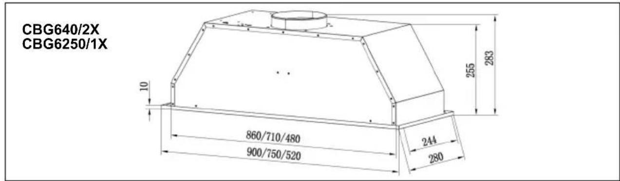
ΤΟΠΟΘΕΤΗΣΗ