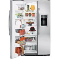
USER MANUAL GSHS5KGXSS GE
Refrigerators Profile Side by Side
Safety Instructions .....2-4
Operating Instructions
Automatic Icemaker 12
Care and Cleaning .....14, 15
ClimateKeeper2™ 6
Crispers and Pans .....11
CustomCool™ 6
Ice and Water Dispenser .....13
Refrigerator Doors ....10
Replacing the Light Bulbs .....16
Shelves and Bins 8,9
Temperature Controls ....5
TurboCool™ 5
Water Filter 7
Installation Instructions
Installing the Refrigerator .....26–29
Moving the Refrigerator .....22-25
Preparing to Install
the Refrigerator .....21
Trim Kits and Panels....17-20
Water Line Installation .....30-32
Troubleshooting Tips .....33-36
Normal Operating Sounds....33
Consumer Support
Consumer Support ....Back Cover
Performance Data Sheet .....41
Product Registration....43, 44
State of California Water
Treatment Device Certificate .....42
Warranty (Canadian) 39
Warranty (U.S.) 40
Write the model and serial numbers here:
Model # ____
Serial # ____
Find these numbers on a label inside the refrigerator compartment at the top on the right side.
Owner's Manual and Installation
Models 23, 25 and 26
Profile Côte à Côte
Réfrigérateurs
Use this appliance only for its intended purpose as described in this Owner's Manual.

SAFETY PRECAUTIONS
When using electrical appliances, basic safety precautions should be followed, including the following:
This refrigerator must be properly installed and located in accordance with the Installation Instructions before it is used.
Do not allow children to climb, stand or hang on the shelves in the refrigerator. They could damage the refrigerator and seriously injure themselves.
- Do not touch the cold surfaces in the freezer compartment when hands are damp or wet. Skin may stick to these extremely cold surfaces.
- Do not store or use gasoline or other flammable vapors and liquids in the vicinity of this or any other appliance.
In refrigerators with automatic icemakers, avoid contact with the moving parts of the ejector mechanism, or with the heating element located on the bottom of the icemaker. Do not place fingers or hands on the automatic icemaking mechanism while the refrigerator is plugged in.
- Keep fingers out of the "pinch point" areas; clearances between the doors and between the doors and cabinet are necessarily small. Be careful closing doors when children are in the area.
■ Unplug the refrigerator before cleaning and making repairs.
NOTE: We strongly recommend that any servicing be performed by a qualified individual.
Setting either or both controls to OFF does not remove power to the light circuit.
- Do not refreeze frozen foods which have thawed completely.
▲ DANGER! RISK OF CHILD ENTRAPMENT
PROPER DISPOSAL OF THE REFRIGERATOR
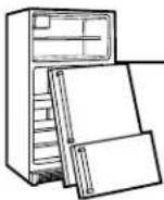
Child entrapment and suffocation are not problems of the past. Junked or abandoned refrigerators are still dangerous...even if they will sit for "just a few days." If you are getting rid of your old refrigerator, please follow the instructions below to help prevent accidents.
Before You Throw Away Your Old Refrigerator or Freezer:
■ Take off the doors.
Leave the shelves in place so that children may not easily climb inside.
Refrigerants
All refrigeration products contain refrigerants, which under federal law must be removed prior to product disposal. If you are getting rid of an old refrigeration product, check with the company handling the disposal about what to do.
USE OF EXTENSION CORDS
Because of potential safety hazards under certain conditions, we strongly recommend against the use of an extension cord.
However, if you must use an extension cord, it is absolutely necessary that it be a UL-listed (in the United States) or a CSA-listed (in Canada), 3-wire grounding type appliance extension cord having a grounding type plug and outlet and that the electrical rating of the cord be 15 amperes (minimum) and 120 volts.
READ ALL INSTRUCTIONS BEFORE USING.
⚠ WARNING!
HOW TO CONNECT ELECTRICITY
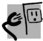
Do not, under any circumstances, cut or remove the third (ground) prong from the power cord. For personal safety, this appliance must be properly grounded.
The power cord of this appliance is equipped with a 3-prong (grounding) plug which mates with a standard 3-prong (grounding) wall outlet to minimize the possibility of electric shock hazard from this appliance.
Have the wall outlet and circuit checked by a qualified electrician to make sure the outlet is properly grounded.
If the outlet is a standard 2-prong outlet, it is your personal responsibility and obligation to have it replaced with a properly grounded 3-prong wall outlet.
The refrigerator should always be plugged into its own individual electrical outlet which has a voltage rating that matches the rating plate.
This provides the best performance and also prevents overloading house wiring circuits which could cause a fire hazard from overheated wires.
Never unplug your refrigerator by pulling on the power cord. Always grip plug firmly and pull straight out from the outlet.
Repair or replace immediately all power cords that have become frayed or otherwise damaged. Do not use a cord that shows cracks or abrasion damage along its length or at either end.
When moving the refrigerator away from the wall, be careful not to roll over or damage the power cord.

SAVE THESE INSTRUCTIONS
natural_image
Line drawing of a refrigerator with open door and shelves (no text or symbols)
flowchart
graph TD
    A["DOOR ALARM"] --> B["ADJUST TEMPERATURE"]
    C["LIGHT"] --> B
    D["RESET FILTER"] --> B
    E["WATER"] --> B
    F["CRUSHED"] --> B
    G["CUBED"] --> B
    H["QUICK ICE"] --> B
    I["LOCK"] --> B
    J["TURBOCOOL"] --> B
    K["0th F Recommended"] --> B
    L["FREEZER"] --> B
    M["REFRIGERATOR"] --> B
    N["COLDER"] --> B
    O["ACTUAL TEMP"] --> B
    P["SET TEMP"] --> B
    Q["37th F Recommended"] --> B
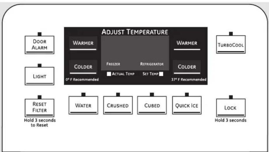
The temperature controls are preset in the factory at 37^ F for the refrigerator compartment and 0^ F for the freezer compartment. Allow 24 hours for the temperature to stabilize to the preset recommended settings.
The temperature controls can display both the SET temperature as well as the actual temperature in the refrigerator and freezer. The actual temperature may vary slightly from the SET temperature based on usage and operating environment.
On some models, setting both controls to the warmest setting until the display flashes (off) will stop cooling in both the freezer and refrigerator compartments.
On other models, setting either control to the warmest setting until the display flashes (off) will stop the cooling to the freezer and refrigerator.
NOTE: Turning the refrigerator off via the controls on the touch panel does not shut off electrical power to the refrigerator.
NOTE: The refrigerator is shipped with protective film covering the temperature controls. If this film was not removed during installation, remove it now.
TurboCool rapidly cools the refrigerator compartment in order to more quickly cool foods. Use TurboCool when adding a large amount of food to the refrigerator compartment, putting away foods after they have been sitting out at room temperature or when putting away warm leftovers. It can also be used if the refrigerator has been without power for an extended period.
Once activated, the compressor will turn on immediately and the fans will cycle on and off at high speed as needed for eight hours. The compressor will continue to run until the refrigerator compartment cools to approximately 34°F (1°C), then it will cycle on and off to maintain this setting. After 8 hours, or if TurboCool is pressed again, the refrigerator compartment will return to the original setting.
How to Use
Press TurboCool. The TurboCool temperature display will show Tc and the LED will be activated. After TurboCool is complete, the TurboCool indicator light will go out.
NOTES: The refrigerator temperature cannot be changed during TurboCool.
The freezer temperature is not affected during TurboCool.
When opening the refrigerator door during TurboCool, the fans will continue to run if they have cycled on.
About ClimateKeeper2.™
flowchart
graph TD
    A["Refrigerator"] --> B{Flow Direction}
    B --> C["Refrigerator with Outer Floor"]
    B --> D["Refrigerator with Inside Floor"]
    B --> E["Refrigerator with Floor"]
    B --> F["Refrigerator with Floor"]
    B --> G["Refrigerator with Floor"]
    style A fill:#f9f,stroke:#333
    style B fill:#ccf,stroke:#333
How it Works
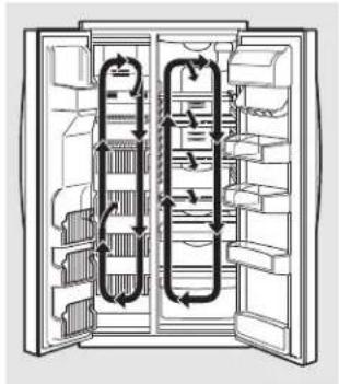
The new ClimateKeeper2™ is the industry's most advanced refrigeration system, delivering optimum temperature and humidity performance to keep food garden fresh longer and reduce freezer burn, while maintaining E star-level efficiency. The new ClimateKeeper2 system features two evaporators—one for the refrigerator and one for the freezer.
This provides two separate cooling systems for the entire unit, and separates the airflow between the fresh food and freezer sections during normal cooling operations.
This ensures that the humidity levels in the fresh food section are significantly higher than in a conventional system, ^* allowing fresh produce and other unsealed foods to retain their moisture content and freshness longer. Moisture sensitive foods such as fresh fruit, salads, rice, etc., can now be stored on open shelves without excessive moisture loss. Due to the higher humidity in the refrigerator, you may on occasion experience fog or small amounts of moisture in the refrigerator compartment. This is normal and may come and go as different food loads and environmental conditions change. Wipe dry with a paper towel if desired.
The separate airflow system minimizes the mixing of air between the two compartments, which reduces odor transfer to improve the taste of ice.
The ClimateKeeper2 system also reduces the number of defrosting cycles in the freezer evaporator, thereby reducing freezer burn.
*Testing shows a higher level of humidity in the Fresh Food section in ClimateKeeper2 refrigerators versus conventional units.
About CustomCool. ^™ (on some models)
natural_image
Line drawing of a refrigerator drawer with shelves and doors (no text or symbols)
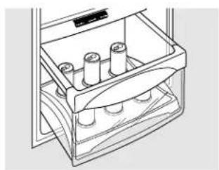
ExpressThaw™
natural_image
Line drawing of a refrigerator drawer with cylindrical objects inside (no text or symbols)
ExpressChill™
How to Use
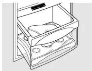
Empty the pan. Place the Chill/Thaw tray in the pan. Place the items on the tray and close the pan completely.
2 LCD Models:
Access by: Home > Options > Refrigerator Options > CustomCool Pan
Non-LCD Models:
Select the ExpressThaw™, ExpressChill™ or SelectTemp™ pad. The display and SET light will come on. Tap the pad until the light appears next to the desired setting. Use the following chart to determine the best setting to use.
■ ExpressChill can be set to 15, 30 or 45 minutes. The default is 15 minutes.
■ To stop a feature before it is finished:
For LCD Models:
Go into that feature's menu and press the OFF button.
For Non-LCD Models:
Tap that feature's pad until no options are selected and the display is off.
During ExpressThaw and ExpressChill, the display on the controls will count down the time in the cycle (on some models).
■ After the ExpressThaw cycle is complete, the pan will reset to the MEAT setting (32°F [0°C]) to help preserve thawed items until they are used.
The displayed actual temperature of the CustomCool pan may vary slightly from the SET temperature based on usage and operating environment.
NOTE: For food safety reasons, it is recommended that foods be wrapped in plastic wrap when using ExpressThaw. This will help contain meat juices and improve thawing performance.
natural_image
Technical line drawing of a mechanical device with no visible text or symbols
6
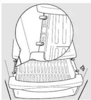
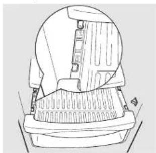
How to Remove and Replace the Drawer
To remove:
7 Pull the drawer out to the stop position.
2 Rotate all four swing locks to the unlock position.
3 Lift the front of the drawer up and out.
To replace:
1 Make sure all four swing locks are in the unlock position.
2 Place the sides of the drawer into the drawer supports, making sure the swing locks fit on the drawer slots.
3 Lock all four swing locks by rotating them to the lock position.
natural_image
Technical line drawing of a mechanical component with no visible text or symbols
Water Filter Cartridge
The water filter cartridge is located in the back upper right corner of the refrigerator compartment.
When to Replace the Filter on Models With a Replacement Indicator Light
There is a replacement indicator light for the water filter cartridge on the dispenser. This light will turn orange to tell you that you need to replace the filter soon.
The filter cartridge should be replaced when the replacement indicator light turns red or if the flow of water to the dispenser or icemaker decreases.
When to Replace the Filter on Models Without a Replacement Indicator Light
The filter cartridge should be replaced every six months or earlier if the flow of water to the water dispenser or icemaker decreases.
Removing the Filter Cartridge
If you are replacing the cartridge, first remove the old one by slowly turning it to the left. Do not pull down on the cartridge. A small amount of water may drip down.
Installing the Filter Cartridge
If you are replacing a SmartWater cartridge with an adapter, it must be removed before installing the cartridge. To remove the adapter, turn it to the left about 1/4 turn.
If you are replacing a Water by Culligan cartridge, leave the adapter in place. This adapter will stay in the refrigerator when you replace future cartridges.
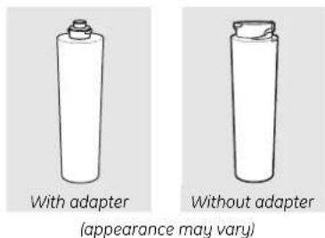
2 On models without a replacement indicator light, apply the month and year sticker to the new cartridge to remind you to replace the filter in six months.
3 Fill the replacement cartridge with water from the tap to allow for better flow from the dispenser immediately after installation.
4 Line up the arrow on the cartridge and the cartridge holder. Place the top of the new cartridge up inside the holder. Do not push it up into the holder.
5 Slowly turn it to the right until the filter cartridge stops. DO NOT OVERTIGHTEN. As you turn the cartridge, it will automatically raise itself into position. The cartridge will move about 1/2 turn.

6 Run water from the dispenser for 3 minutes (about 1-1/2 gallons) to clear the system and prevent sputtering.
7 Press and hold the WATER FILTER pad (on some models) on the dispenser for 3 seconds.
NOTE: A newly-installed water filter cartridge may cause water to spurt from the dispenser.
Filter Bypass Plug
You must use the filter bypass plug when a replacement filter cartridge is not available. The dispenser and the icemaker will not operate without the filter or filter bypass plug.
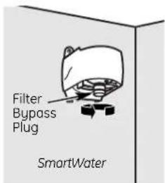
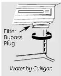
To use the filter bypass plug on Water by Culligan models, you must first remove the filter adapter from the cartridge holder by turning it to the left.
If you have questions—visit our Website at ge.com, or call 1.800.GE.CARES (1.800.432.2737).
Replacement filters:
To order additional filter cartridges in the United States, visit our Website at ge.com, or call GE Parts and Accessories, 800.626.2002.
MSWF
Suggested Retail \$36.95–41.95
Customers in Canada should consult the yellow pages for the nearest Mabe Service Center.
About the shelves and bins.
Not all features are on all models.
Refrigerator bin
natural_image
Technical line drawing of a mechanical component or bracket (no text or symbols visible)
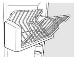
Freezer tilt-out bin
Refrigerator Door Bins and Freezer Door Tilt-Out Bins
Large Bins
The larger refrigerator door bins and freezer tilt-out door bins are adjustable.
To remove: Lift the front of the bin straight up, then lift up and out.
To replace or relocate: Engage the back side of the bin in the molded supports on the door. Then push down on the front of the bin. Bin will lock in place.
Small Bins
To remove: Lift the front of the bin straight up then out.
To replace: Position the bin above the rectangular molded supports on the door. Then slide the bin down onto the support to lock it in place.
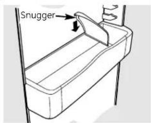
The snugger helps prevent tipping, spilling or sliding of small items stored on the door shelf. Place a finger on either side of the snugger near the rear and move it back and forth to fit your needs.
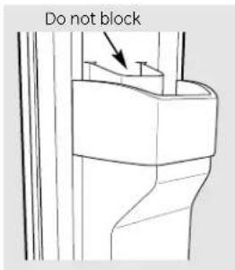
Top freezer bin
CAUTION:
Be careful when placing items in the top bin. Make sure that items do not block or fall into the ice chute.
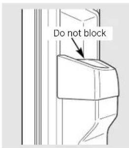
Top freezer bin (on some models)
CAUTION:
Part must be in place as shown for proper ice dispensing. Food cannot be stored in this location.
natural_image
Pure diagram of a mechanical or architectural component with no visible text, numbers, or symbols
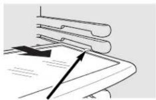
Press tab and pull shelf forward to remove
natural_image
Abstract line drawing with two black arrows pointing upward, no text or symbols present
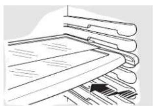
Slide-Out Spillproof Shelf
The slide-out spillproof shelf allows you to reach items stored behind others. The special edges are designed to help prevent spills from dripping to lower shelves.
To remove:
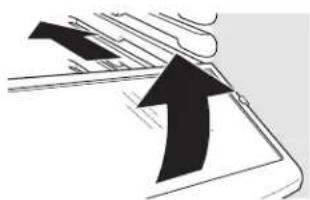
Slide the shelf out until it reaches the stop, then press down on the tab and slide the shelf straight out.
To replace or relocate:
Line the shelf up with the supports and slide it into place. The shelf can be repositioned when the door is at 90° or more. To reposition the shelf, slide the shelf past the stops and angle downward. Slide shelf down to the desired position, line up with the supports and slide into place.
Make sure you push the shelves all the way back in before you close the door.
natural_image
Illustration of stacked documents with a pen and a black arrow pointing to a document (no text or symbols present)
8
QuickSpace™ Shelf
This shelf splits in half and slides under itself for storage of tall items on the shelf below.
This shelf can be removed and replaced or relocated just like the Slide-Out Spillproof Shelves.
On some models, this shelf cannot be used in the lowest position.
Not all features are on all models.
natural_image
Line drawing of a rectangular metal rack with internal ribs and a flat base (no text or symbols)
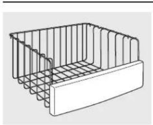
Freezer Baskets
To remove, push the basket all the way to the back of the freezer. Lift up until the back pins are disengaged. Lift the entire basket up and pull out.
Make sure you push the baskets all the way back in before you close the door.
natural_image
Technical line drawing of a metal rack with a black bracket and vertical supports (no text or symbols)
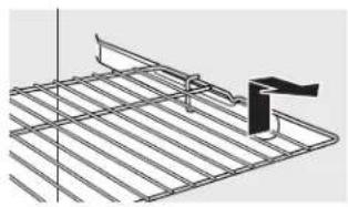
Slide-Out Freezer Shelves
To remove, slide out to the stop position, lift the front past the stop position and slide out.
Make sure you push the shelves all the way back in before you close the door.
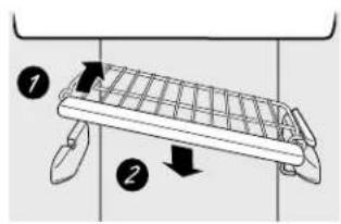
Fixed Freezer Shelves
There are two types of fixed freezer shelves.
NOTE FOR DISPENSER MODELS: In order to take full advantage of the tilt-out ice bin, only store items on the shelf below the ice bin that are no taller than the lowest point on the bin.
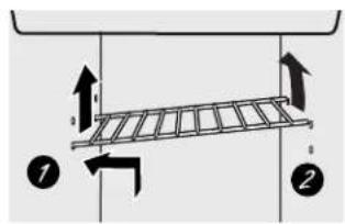
To remove this type of shelf:
1 Lift the shelf up at the left side.
2 Bring the shelf out.
To remove this type of shelf:
7 Lift up the left side of the shelf and slide it left into the center of the shelf supports.
2 Rotate the right side of the shelf up and out of the shelf supports.
natural_image
Line drawing of a mechanical device with rollers and a curved housing (no text or symbols)
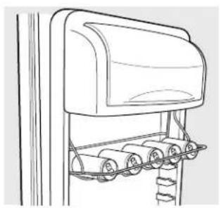
Door Wine/Beverage Rack (on some models)
This rack holds up to 5 cans or one bottle of wine.
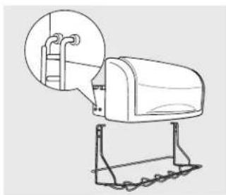
The rack hangs from the sides of the dairy bin.
To remove:
1 Empty the wine/beverage rack.
2 Holding the bottom of the dairy bin, lift the front straight up, then lift up and out.
3 To detach the rack from the dairy bin, pull the rack's side wires out of the holes on each side of the dairy bin.
To replace:
1 Reattach the rack to the sides of the bin.
2 Engage the back side of the bin in the molded supports on the door. Then push down on the front of the bin. The bin will lock into place.
natural_image
Line drawing of a mailbox with a magnified inset showing its structure (no text or symbols)
About the refrigerator doors.
natural_image
Technical line drawing of a mechanical device with internal components and directional arrows indicating motion (no text or symbols)
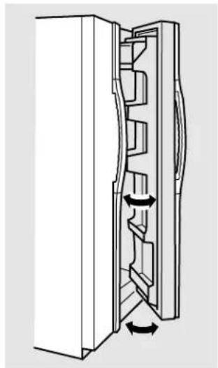
When the door is only partially open, it will automatically close.
Beyond this stop the door will stay open.
Refrigerator Doors
The refrigerator doors may feel different than the ones you are used to. The special door opening/closing feature makes sure the doors close all the way and are securely sealed.
When opening and closing the door you will notice a stop position. If the door is opened past this stop point, the door will remain open to allow you to load and unload food more easily. When the door is only partially open, it will automatically close.
The resistance you feel at the stop position will be reduced as the door is loaded with food.
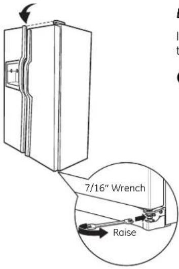
Door Alignment
If doors are uneven, adjust the refrigerator door.
Using a 7/16" wrench, turn the door adjusting screw to the right to raise the door, to the left to lower it. (A nylon plug, imbedded in the threads of the pin, prevents the pin from turning unless a wrench is used.)
2 After one or two turns of the wrench, open and close the refrigerator door and check the alignment at the top of the doors.
About the crispers and pans. ge.com
Not all features are on all models.
natural_image
Line drawing of a refrigerator with three shelves (no text or symbols)
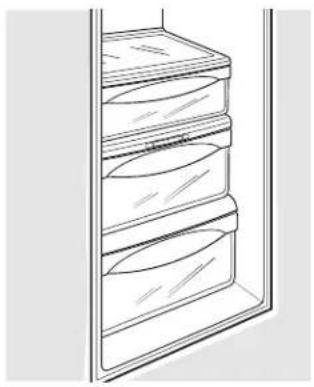
Fruit and Vegetable Crispers
Excess water that may accumulate in the bottom of the drawers should be wiped dry.
On some models, the bottom drawer has full extension slides that allow full access to the drawer.
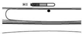
Adjustable Humidity Crispers
Slide the control all the way to the HI setting to provide high humidity recommended for most vegetables.
Slide the control all the way to the LO setting to provide lower humidity levels recommended for most fruits.
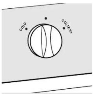
Convertible Deli Pan
The convertible deli pan has its own cold air duct to allow a stream of cold air from the freezer compartment or fresh food compartment to flow to the pan.
The variable temperature control regulates the air flow from the Climate Keeper Air Tower.
Set the control to the coldest setting to store fresh meats.
Set the control to cold to convert the pan to normal refrigerator temperature and provide extra vegetable storage space. The cold air duct is turned off. Variable settings between these extremes can be selected.
About crisper removal.
Not all features are on all models.

natural_image
Pure technical line drawing of a mechanical component with no text or symbols
Crisper Removal
Crispers can easily be removed by pulling the drawer straight out and lifting the drawer up and over the stop location.
If the door prevents you from taking out the drawers, first try to remove the door bins. If this does not offer enough clearance, the refrigerator will need to be rolled forward until the door opens enough to slide the drawers out. In some cases, when you roll the refrigerator out, you will need to move the refrigerator to the left or right as you roll it out.
About the automatic icemaker.
A newly installed refrigerator may take 12 to 24 hours to begin making ice.
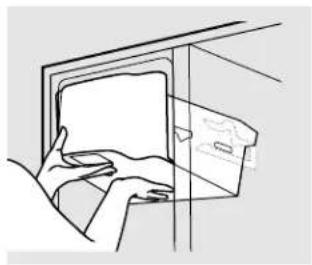
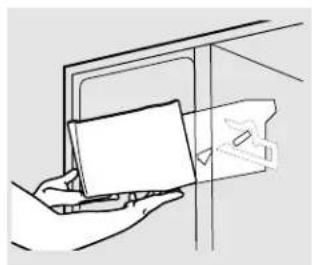
On dispenser models, to access ice or reach the power switch:
natural_image
Line drawing of a hand inserting a card into a cabinet (no text or symbols)
1 Lift the bin, then pull it forward until the bin stops.
natural_image
Line drawing of a hand holding a card inside a door (no text or symbols)
2 Lower the bin to access ice or reach the power switch.
NOTE: In order to take full advantage of the tilt-out ice bin, only store items on the shelf below the ice bin that are no taller than the lowest point on the bin.
Automatic Icemaker
The icemaker will produce seven cubes per cycle—approximately 100–130 cubes in a 24-hour period, depending on freezer compartment temperature, room temperature, number of door openings and other use conditions.
If the refrigerator is operated before the water connection is made to the icemaker, set the power switch in the OFF position.
When the refrigerator has been connected to the water supply, set the power switch to the ON position.
The icemaker will fill with water when it cools to 15°F (-10°C). A newly installed refrigerator may take 12 to 24 hours to begin making ice cubes.
You will hear a buzzing sound each time the icemaker fills with water.
Throw away the first few batches of ice to allow the water line to clear.
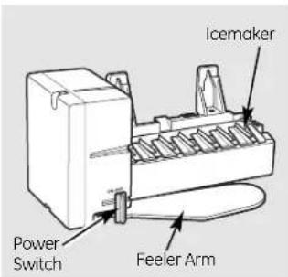
Be sure nothing interferes with the sweep of the feeler arm.
When the bin fills to the level of the feeler arm, the icemaker will stop producing ice. It is normal for several cubes to be joined together.
If ice is not used frequently, old ice cubes will become cloudy, taste stale and shrink.
Special note about dispenser models:
- Dispenser models have a tilt-out ice bin. The bin can be tilted out as shown in the illustrations, and it will hold itself up while you take ice out or turn the icemaker power switch on and off. Be sure to put the bin back in place before closing the door.
■ To restore your ice level from an empty bucket stage, the following steps are recommended:
12 hours after the first batch of ice has fallen into the bin, dispense 3 to 4 cubes.
2 After an additional 6 hours, dispense 3 to 4 cubes again.
These steps will restore your ice level in the shortest amount of time.
natural_image
Line drawing of a hand inserting a device into a wall (no text or symbols)
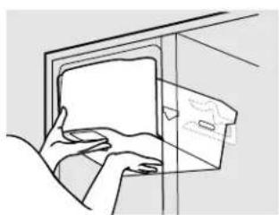
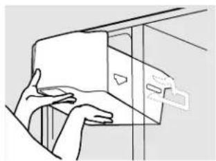
1 Lift the bin, then pull it forward until the bin stops.
natural_image
Line drawing of a hand holding a rectangular object with a small inset view (no text or symbols)
2 Lift and pull forward again to remove the bin.
Removing Ice Bin (dispenser models)
CAUTION: The ice bin is heavy when full.
Set the power switch to the OFF position before removing the bin.
When replacing the bin, be sure to press it firmly into place. If it does not go all the way back, remove it and rotate the drive mechanism 1/4 turn. Then push the bin back again.
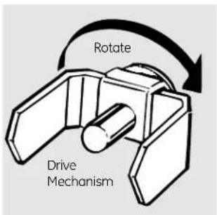
Dispenser Models only
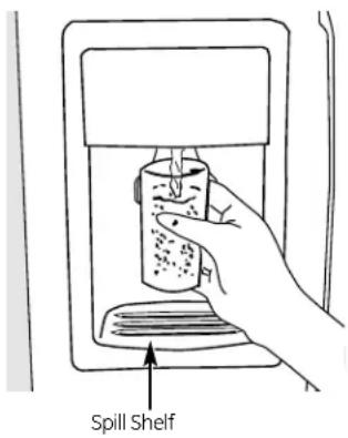
To Use the Dispenser
Select CUBED ICE, CRUSHED ICE or WATER.
Press the glass gently against the top of the dispenser cradle.
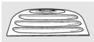
The spill shelf is not self-draining. To reduce water spotting, the shelf and its grille should be cleaned regularly.
If no water is dispensed when the refrigerator is first installed, there may be air in the water line system. Press the dispenser arm for at least two minutes to remove trapped air from the water line and to fill the water system. To flush out impurities in the water line, throw away the first six glassfuls of water.
CAUTION: Never put fingers or any other objects into the ice crusher discharge opening.
Locking the Dispenser
Press the LOCK pad for 3 seconds to lock the dispenser and control panel. To unlock, press and hold the pad again for 3 seconds.
Dispenser Light
The LIGHT pad turns the night light in the dispenser on and off. The light also comes on when the dispenser cradle is pressed. On some models, if this light burns out, it should be replaced with a 6 watt 12V maximum bulb.
Quick Ice
When you need ice in a hurry, press the QUICK ICE pad to speed up ice production. This will increase ice production for the following 48 hours or until you press the pad again.
Door Alarm
To set the alarm, press the DOOR ALARM pad until the indicator light comes on. This alarm will sound if either door is open for more than 3 minutes. The light goes out and the beeping stops when you close the door.
Precise Fill
This water dispenser is equipped with a feature called "precise fill." This feature allows you to choose a precise amount of water (cups or ounces) that you would like dispensed.
1 Press the WATER pad.
2 Press the CUPS or OUNCES pad.
3 Select the precise amount of water you would like dispensed.
If you selected OUNCES, press the arrow pads on either side of the display to select the number of ounces you would like to have dispensed between 1–99 ounces.
If you selected CUPS, press the arrow pads on the left of the display to select the whole cups (1-16 cups) and/or the arrow pads on the right side of the display to select fractions of a cup (1/4-3/4 cups).
4 Press the cup against the cradle and water will begin dispensing. It will automatically stop when the amount set has been dispensed. The display will show there is no water left to dispense, then reset.
NOTE: Do not leave the dispenser unattended when water is being dispensed.
5 If you would like to stop dispensing water before the specified amount has been dispensed, just remove the cup from the cradle. The display will show the amount left to dispense.
Important Facts About Your Dispenser
- Do not add ice from trays or bags to the storage drawer. It may not crush or dispense well.
■ Avoid overfilling glass with ice and use of narrow glasses. Backed-up ice can jam the chute or cause the door in the chute to freeze shut. If ice is blocking the chute, poke it through with a wooden spoon.
■ Beverages and foods should not be quick-chilled in the ice storage drawer. Cans, bottles or food packages in the storage drawer may cause the icemaker or auger to jam.
■ To keep dispensed ice from missing the glass, put the glass close to, but not touching, the dispenser opening.
Some crushed ice may be dispensed even though you selected CUBED ICE. This happens occasionally when a few cubes accidentally get directed to the crusher.
■ After crushed ice is dispensed, some water may drip from the chute.
Sometimes a small mound of snow will form on the door in the ice chute. This condition is normal and usually occurs when you have dispensed crushed ice repeatedly. The snow will eventually evaporate.
Care and cleaning of the refrigerator.
natural_image
Simple line drawing of a three-tiered oval-shaped object with a central hole (no text or symbols)
Dispenser drip area.
Cleaning the Outside
The dispenser drip area, beneath the grille, should be wiped dry. Water left in this area may leave deposits. Remove the deposits by adding undiluted vinegar to the well. Soak until the deposits disappear or become loose enough to rinse away.
The dispenser cradle. Before cleaning, lock the dispenser by pressing and holding the LOCK pad for 3 seconds. Clean with warm water and baking soda solution—about a tablespoon (15 ml) of baking soda to a quart (1 liter) of water. Rinse thoroughly and wipe dry.
The door handles and trim. Clean with a cloth dampened with soapy water. Dry with a soft cloth.
The stainless steel panels and door handles (on some models) can be cleaned with a commercially available stainless steel cleaner. A spray-on stainless steel cleaner works best.
Do not use appliance wax or polish on the stainless steel.
Keep the outside clean. Wipe with a clean cloth lightly dampened with kitchen appliance wax or mild liquid dish detergent. Dry and polish with a clean, soft cloth.
Do not wipe the refrigerator with a soiled dish cloth or wet towel. These may leave a residue that can erode the paint. Do not use scouring pads, powdered cleaners, bleach or cleaners containing bleach because these products can scratch and weaken the paint finish.
Cleaning the Inside
To help prevent odors, leave an open box of baking soda in the fresh food and freezer compartments.
Unplug the refrigerator before cleaning. If this is not practical, wring excess moisture out of sponge or cloth when cleaning around switches, lights or controls.
Use warm water and baking soda solution—about a tablespoon (15 ml) of baking soda to a quart (1 liter) of water. This both cleans and neutralizes odors. Rinse and wipe dry.
Use of any cleaning solution other than that which is recommended, especially those that contain petroleum distillates, can crack or damage the interior of the refrigerator.
Avoid cleaning cold glass shelves with hot water because the extreme temperature difference may cause them to break. Handle glass shelves carefully. Bumping tempered glass can cause it to shatter.
Do not wash any plastic refrigerator parts in the dishwasher.
The chill/thaw tray is dishwasher safe.
Behind the Refrigerator
Be careful when moving the refrigerator away from the wall. All types of floor coverings can be damaged, particularly cushioned coverings and those with embossed surfaces.
Pull the refrigerator straight out and return it to position by pushing it straight in. Moving the refrigerator in a side direction may result in damage to the floor covering or refrigerator.
When pushing the refrigerator back, make sure you don't roll over the power cord or icemaker supply line.
Preparing for Vacation
For long vacations or absences, remove food and unplug the refrigerator. Clean the interior with a baking soda solution of one tablespoon (15 ml) of baking soda to one quart (1 liter) of water. Leave the doors open.
Set the icemaker power switch to the OFF position and shut off the water supply to the refrigerator.
If the temperature can drop below freezing, have a qualified servicer drain the water supply system to prevent serious property damage due to flooding.
Preparing to Move
Secure all loose items such as shelves and drawers by taping them securely in place to prevent damage.
When using a hand truck to move the refrigerator, do not rest the front or back of the refrigerator against the hand truck. This could damage the refrigerator. Handle only from the sides of the refrigerator.
Be sure the refrigerator stays in an upright position during moving.
Replacing the light bulbs.
Setting the controls to OFF does not remove power to the light circuit.
Reveal® appliance bulbs are used on some models. They can be identified by their blue color when they are not illuminated.
Not all features are on all models.
Your light shield will look like one of the following:
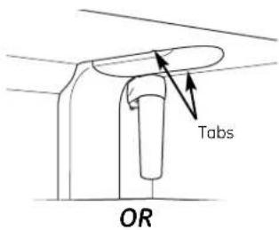
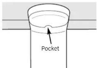
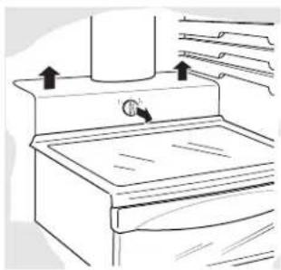
Refrigerator Compartment—Upper Light
1 Unplug the refrigerator.
2 The bulbs are located at the top of the compartment, inside the light shield. On some models, a screw at the front of the light shield will have to be removed. On other models, the screw is located in the pocket located at the back of the light shield.
3 To remove the light shield, on some models, press in on the tabs on the sides of the shield and slide forward and out. On other models, just slide the shield forward and out.
4 After replacing the bulb with an appliance bulb of the same or lower wattage, replace the light shield and screws (on some models). When replacing the light shield, make sure that the tabs at the back of the shield fit into the slots at the back of the light shield housing.
5 Plug the refrigerator back in.
natural_image
Line drawing of a kitchen appliance with a handle and ventilation unit (no text or symbols)
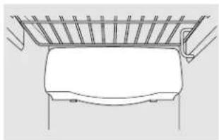
Refrigerator Compartment—Lower Light
This light is located above the top drawer.
1 Unplug the refrigerator.
2 Remove the convertible meat drawer control knob by pulling straight out.
3 Lift the light shield up and pull it out.
4 After replacing the bulb with an appliance bulb of the same or lower wattage, replace the shield and the knob.
5 Plug the refrigerator back in.
natural_image
Simple line drawing of a mechanical component with no text or symbols
Freezer Compartment
1 Unplug the refrigerator.
2 Remove the shelf just above the light shield. (The shelf will be easier to remove if it is emptied first.) On some models, a screw at the top of the light shield will need to be removed.
3 To remove the light shield, press in on the sides, and lift up and out.
4 Replace the bulb with an appliance bulb of the same or lower wattage, and reinstall the light shield. When reinstalling the light shield, make sure the top tabs snap securely into place. Replace the screw (on some models).
5 Reinstall the shelf and plug the refrigerator back in.
Dispenser (on some models)
1 Unplug the refrigerator.
2 The bulb is located on the dispenser under the control panel. Remove the light bulb by turning it counterclockwise.
3 Replace the bulb with a bulb of the same size and wattage.
4 Plug the refrigerator back in.
Trim kits and decorator panels.
For CustomStyle™ models
Read these instructions completely and carefully.

Before You Begin
Some models are equipped with trim kits that allow you to install door panels. You can order pre-cut black, white, bisque or stainless steel decorator panels from GE Parts and Accessories, 800.626.2002, or you can add wood panels to match your kitchen cabinets.
Panels less than 1/4" (6 mm) thick
When installing wood panels less than 1/4" (6 mm) thick, you need to create a filler panel, such as 1/8" cardboard, that will fit between the face of the door and the wood panel. If you are installing the pre-cut decorator panels, pre-cut filler panels are included in the kit. The combined thickness of the decorator or wood panel and the filler panel should be 1/4" (6 mm).
Panels 1/4" thick or less
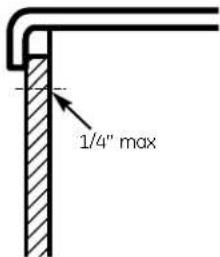
3/4" (19 mm) or Raised Panel
A raised panel design screwed or glued to a 1/4" (6 mm) thick backing, or a 3/4" (19 mm) routed board can be used. The raised portion of the panel must be fabricated to permit clearances of at least 2" (5.1 cm) from the handle side for fingertip clearance.
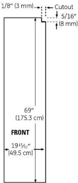
Panels thicker than 1/4" (6 mm), up to 3/4" (19 mm) max, will require that the outer 5/16" (8 mm) of panel perimeter be no thicker than 1/4" (6 mm).
Weight limitations for custom panels:
Fresh Food 38 lbs. (17 kg) max.
Freezer Door 28 lbs. (13 kg) max.
Panels thicker than 1/4" (6 mm)
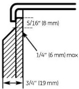
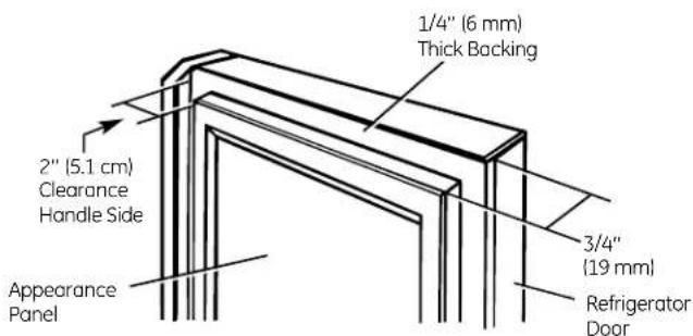
Trim kits and decorator panels.
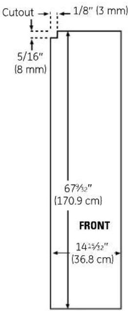
23' Dimensions for Custom Wood Panels
The areas at the top of the panels need to be cut out of the panels.
Freezer Panel
Without Dispenser
Freezer Panel
With Dispenser Fresh Food Panel
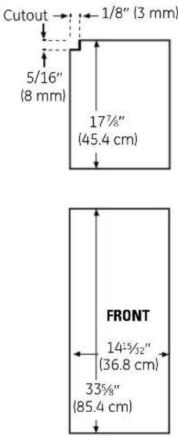
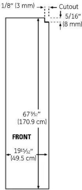
25' CustomStyle™ Dimensions for Custom Wood Panels
The areas at the top of the panels need to be cut out of the panels.
Freezer Panel
Without Dispenser
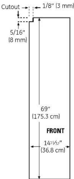
Freezer Panel
With Dispenser Fresh Food Panel
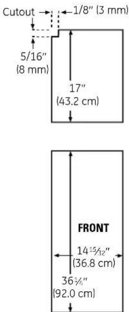
Read these instructions completely and carefully.
⑦ Insert the Freezer Panel and Fresh Food Panel.
Carefully push the freezer panel in until it slides into the slot behind the door handle. Push the filler panel (required with some door panels) in behind the decorator panel. Repeat for fresh food panel.
If your model has a dispenser, this step only applies to the fresh food panel and top freezer panel.
2 Insert the Bottom Freezer Panel (on dispenser models).
Carefully push the panel in until it slides into the slot behind the door handle. Push the filler panel (required
with some door panels) in behind the decorator panel.
3 Attach the Top Trim on the Freezer and Fresh Food Doors.
The Top Trim can be found inside the refrigerator compartment.
With a T-20 Torxdriver, attach the Top Trim, using two screws on each Top Trim piece, to the top of
each door. Hand tighten only. Make sure that the top of each panel fits snugly behind the lip of the Top Trim.
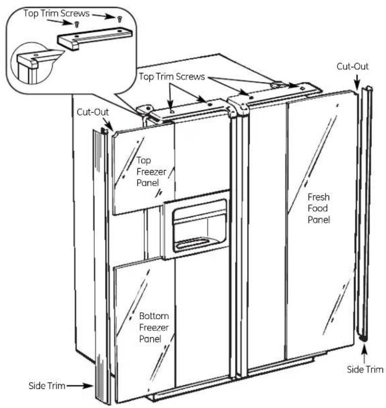
Inserting the door panels.
4 Install the Side Trim.
These pieces are tucked inside the refrigerator door handle.
Do not remove the protective film on the outside of the Side Trim until the Side Trim is installed.
Fit the bottom of the Side Trim under the Bottom Trim as illustrated.
Hold the Side Trim against the front face of the decorator panels and fit the Side Trim under the Top Trim. Make sure the magnetically attached Side Trim is fitted correctly and that you are satisfied with the appearance of all the parts.
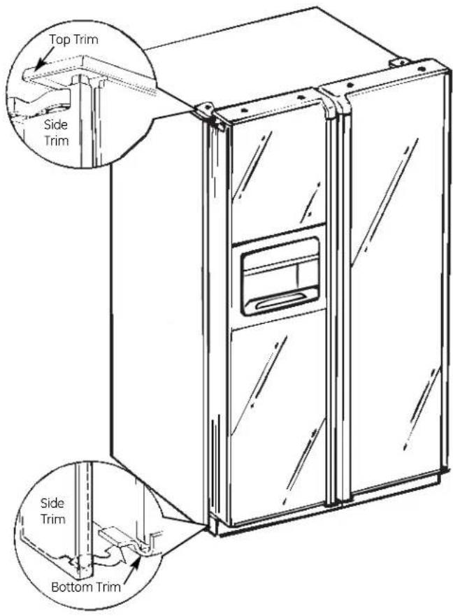
Installation Instructions
Refrigerator
Models 23, 25 and 26
Questions? Call 800.GE.CARES (800.432.2737) or Visit our Website at: ge.com In Canada, call 1.800.561.3344 or Visit our Website at: geappliances.ca
BEFORE YOU BEGIN
Read these instructions completely and carefully.
- IMPORTANT — Save these instructions for local inspector's use.
- IMPORTANT – Observe all governing codes and ordinances.
- Note to Installer – Be sure to leave these instructions with the Consumer.
- Note to Consumer – Keep these instructions for future reference.
- Skill level – Installation of this appliance requires basic mechanical skills.
- Completion time – Refrigerator Installation 30 minutes
Water Line Installation
30 minutes
- Proper installation is the responsibility of the installer.
- Product failure due to improper installation is not covered under the Warranty.
If the refrigerator has already been installed, remove the base grille (see Step 2 in Moving the Refrigerator), then skip to Step 5 in Installing the Refrigerator.
PREPARATION
WATER SUPPLY TO THE ICEMAKER
If the refrigerator has an icemaker, it will have to be connected to a cold water line. A GE water supply kit (containing tubing, shutoff valve, fittings and instructions) is available at extra cost from your dealer, by visiting our Website at ge.com (in Canada at geappliances.ca) or from Parts and Accessories, 800.626.2002 (in Canada 1.800.661.1616).
TOOLS YOU WILL NEED
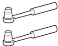
3/8" and 5/16" Socket
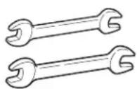
1/2" and 7/16" Wrench
natural_image
Diagram of a screwdriver with a magnified view of the tip (no text or symbols)
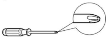
Phillips Head Screwdriver
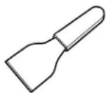
Plastic Putty Knife
MOVING THE REFRIGERATOR
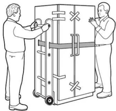
① LOADING THE REFRIGERATOR ONTO A HAND TRUCK
Leave all tape and door pads on doors until the refrigerator is in its final location.
To move the refrigerator, use a padded hand truck. Center the refrigerator on the hand truck and secure the strap around the refrigerator. DO NOT OVERTIGHTEN THE STRAP.
natural_image
Two men standing beside a large industrial machine with control panels and no visible text or symbols
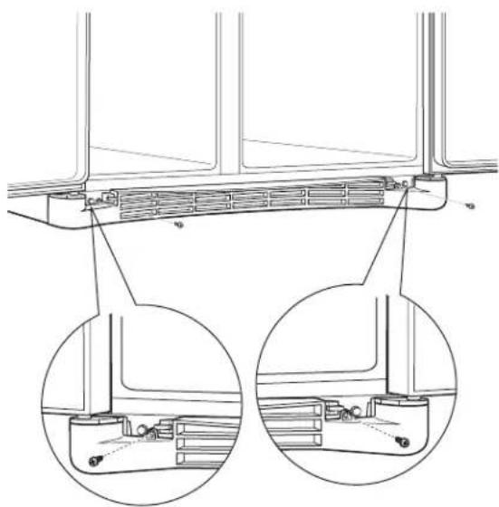
② REMOVE THE BASE GRILLE
Remove the grille by removing the two Phillips head screws.
natural_image
Technical line drawing of a structural component with two circular insets showing internal components (no text or symbols)
If the refrigerator must go through any entrance that is less than 38" wide, the doors must be removed. Proceed to Step 3.
DO NOT remove the handles.
If all entrances are more than 38" wide, skip to Installing the Refrigerator.
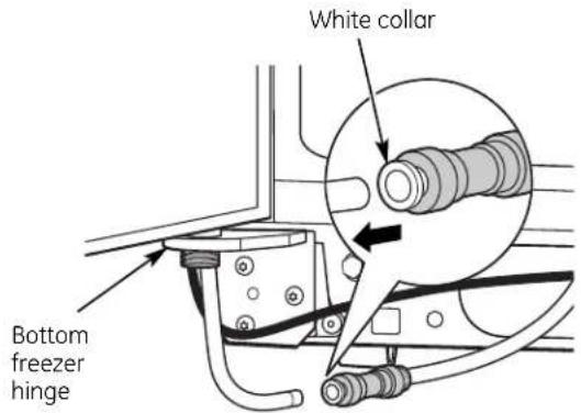
③ DISCONNECT THE WATER COUPLING (on some models)
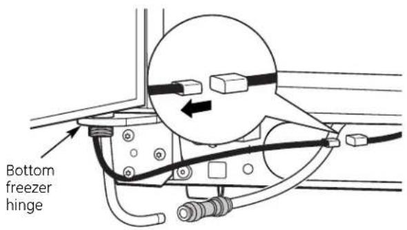
If the refrigerator has a water dispenser, there is a water line from the cabinet into the bottom hinge on the freezer door that must be disconnected.
To disconnect, push in on the white collar of the coupling and pull out the tubing.
4 DISCONNECT THE POWER COUPLING (on some models)
If the refrigerator has a water dispenser, there is a power line (harness) from the cabinet into the bottom hinge on the freezer door that must be disconnected.
To disconnect, pull apart at the coupling.
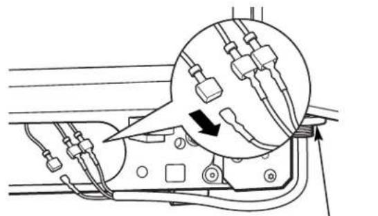
5 DISCONNECT THE ELECTRICAL CONNECTORS (on some models)
If the refrigerator has a refreshment center, there are electrical connectors (harnesses) from the cabinet into the bottom hinge on the refrigerator door that must be disconnected.
To disconnect, pull apart each connector.
natural_image
Technical diagram of electrical wiring connections with a magnified inset showing cable routing (no text or labels)
Bottom refrigerator hinge
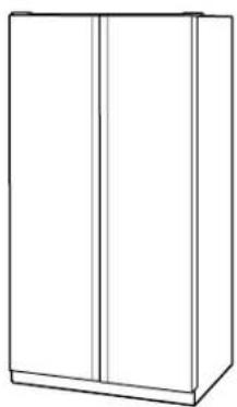
⑥ CLOSE THE FREEZER AND REFRIGERATOR DOORS
natural_image
Line drawing of a two-panel cabinet or rack unit (no text or symbols)
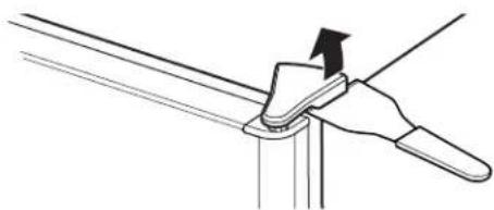
7 REMOVE THE FREEZER DOOR
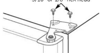
A Remove the freezer door top hinge cover (if equipped) by either squeezing it and pulling it up or by prying it off with a plastic putty knife.
natural_image
Diagram of a hand using a tool to lift a metal sheet (no text or symbols present)
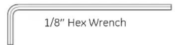
B Remove the two 5/16" or 1/8" hex head screws, then lift the hinge straight up to free the hinge pin.
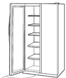
C Open the freezer door to 90.°
natural_image
Line drawing of a refrigerator with open doors and shelves (no text or symbols)
90°
MOVING THE REFRIGERATOR (CONT.)
7 REMOVE THE FREEZER DOOR (cont.)
D As one person slowly lifts the freezer door up and off the bottom hinge, the second person should carefully guide the water line and power line (harness) through the bottom hinge.
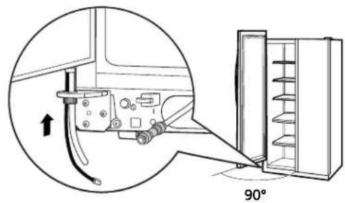
E Set the door on a non-scratching surface with the inside up.
8 REMOVE THE REFRIGERATOR DOOR
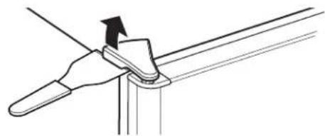
A Remove the refrigerator door top hinge cover (if equipped) by either squeezing it and pulling it up or by prying it off with a plastic putty knife.
natural_image
Diagram of a hand holding a tool with an arrow indicating direction (no text or symbols present)
8 REMOVE THE REFRIGERATOR DOOR (cont.)
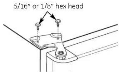
B Remove the two 5/16" or 1/8" hex head screws, then lift the hinge straight up to free the hinge pin.
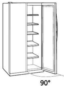
C Open the refrigerator door to 90.°
natural_image
Line drawing of a refrigerator with open door and side shelves, labeled 90° (no text or symbols on the diagram itself)
⑧ REMOVE THE REFRIGERATOR DOOR (cont.)
D Lift the refrigerator door up and off the bottom hinge.
If the refrigerator has a refreshment center, one person should slowly lift the door up and off the bottom hinge and the second person should carefully guide the electrical lines (harnesses) through the bottom hinge.
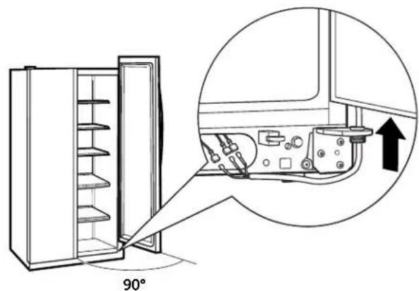
Refreshment Center Models Only
E Set the door on a non-scratching surface with the inside up.
9 REPLACING THE DOORS
To replace the doors, simply reverse steps 3 through 8.
However, please note the following:
- When lowering the doors onto the bottom hinges, make sure the second person carefully guides the tube and harnesses through the holes in the hinges.
- When connecting the water line, make sure you insert the tubing all the way to the mark.
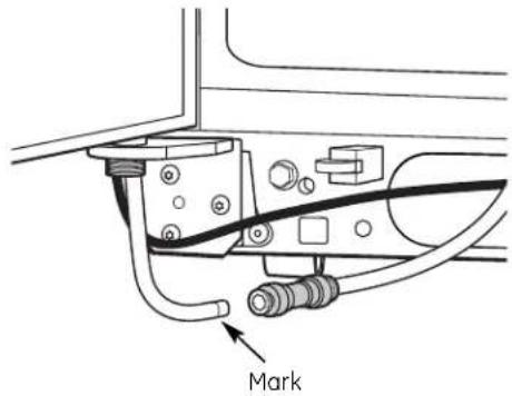
- Do not pinch the tubing and harnesses when placing the doors on the bottom hinges.
- When connecting the power line and the electrical lines (refreshment center models only), be sure that the connectors are seated together fully.
INSTALLING THE REFRIGERATOR
REFRIGERATOR LOCATION
- Do not install the refrigerator where the temperature will go below 60^ (16°C) because it will not run often enough to maintain proper temperatures.
- Do not install the refrigerator where the temperature will go above 100^ (37°C) because it will not perform properly.
• Install it on a floor strong enough to support it fully loaded.
CLEARANCES
Allow the following clearances for ease of installation, proper air circulation and plumbing and electrical connections:
| 23'/25' CustomStyleTM | 23' (33" wide), 25', 26' |
| Sides | 1/8" (4 mm) | 1/8" (4 mm) |
| Top | 1" (25 mm) | 1" (25 mm) |
| Back | 1/2" (13 mm) | 1" (25 mm) |
DIMENSIONS AND SPECIFICATIONS (for 23' CustomStyle™ models)
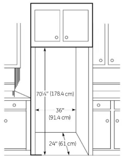
DIMENSIONS AND SPECIFICATIONS
![Water Electrical 3/4" (19 mm) Airspace (1/2" [13 mm] Gap + 1/4" [6 mm] Wall Plates) 24" (61 cm) Cabinet 25" (63.5 cm) Countertop](/content/2026/03/527913/images/3c79d35285464ca8bdd22ea1eca6c5245a46591c9796a7ac09ed0f4ad24fd346.jpg)
DIMENSIONS AND SPECIFICATIONS (for 25' CustomStyle™ models)
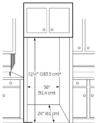
*72 ^1/4 " (183.5 cm) required for full adjustment of mobility wheels. If cabinets installed above refrigerator have doors that are flush to the top of the opening for the refrigerator, then an additional 1/8" may be required to provide clearance for cabinet doors to open freely.
① CONNECTING THE REFRIGERATOR TO THE HOUSE WATER LINE (icemaker and dispenser models)
A cold water supply is required for automatic icemaker and dispenser operation. If there is not a cold water supply, you will need to provide one. See Installing the Water Line section.
NOTES:
- Before making the connection to the refrigerator, be sure the refrigerator power cord is not plugged into the wall outlet.
- If your refrigerator does not have a water filter, we recommend installing one if your water supply has sand or particles that could clog the screen of the refrigerator's water valve. Install it in the water line near the refrigerator. If using GE SmartConnect™ Refrigerator Tubing Kit, you will need an additional tube (WX08X10002) to connect the filter. Do not cut plastic tube to install filter.
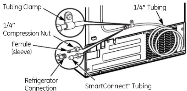
A If you are using copper tubing, place a compression nut and ferrule (sleeve) onto the end of the tubing coming from the house cold water supply.
If you are using the GE SmartConnect™ tubing, the nuts are already assembled to the tubing.
B If you are using copper tubing, insert the end of the tubing into the refrigerator connection, at the back of the refrigerator, as far as possible. While holding the tubing, tighten the fitting.
If you are using GE SmartConnect™ tubing, insert the molded end of the tubing into the refrigerator connection, at the back of the refrigerator, and tighten the compression nut until it is hand tight. Then tighten one additional turn with a wrench. Overtightening may cause leaks.
C Fasten the tubing into the clamp provided to hold it in position. You may need to pry open the clamp.
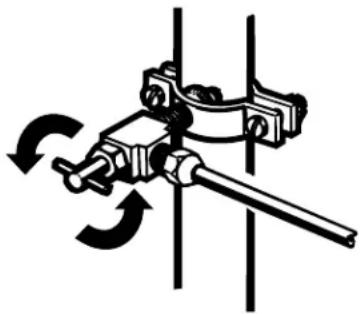
② TURN ON THE WATER SUPPLY
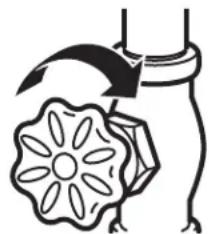
Turn the water on at the shutoff valve (house water supply) and check for any leaks.
natural_image
Mechanical clamp mechanism diagram showing rotational motion with no text or symbols
3 PLUG IN THE REFRIGERATOR
Before plugging in the refrigerator, make sure the icemaker power switch is set to the OFF position.
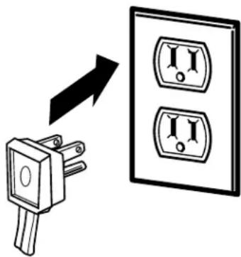
See the grounding information attached to the power cord.
INSTALLING THE REFRIGERATOR (CONT.)
4 PUT THE REFRIGERATOR IN PLACE
Move the refrigerator to its final location.
The refrigerator can be leveled by adjusting the rollers located near the bottom hinges.
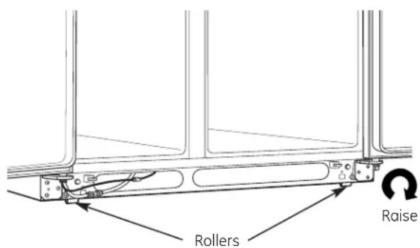
Rollers have three purposes:
- Rollers adjust so the door closes easily when opened about halfway. (Raise the front about 5/8" [16 mm] from the floor.)
- Rollers adjust so the refrigerator is firmly positioned on the floor and does not wobble.
- Rollers allow you to move the refrigerator away from the wall for cleaning.
To adjust the rollers on 23' (33" wide), 25' and 26' models:
- Turn the roller adjusting screws clockwise to raise the refrigerator, counterclockwise to lower it. Use a 3/8" hex socket or wrench, or an adjustable wrench.

natural_image
Mechanical assembly diagram showing a lever mechanism with no visible text or symbols
Roller adjusting screw
5 LEVEL THE REFRIGERATOR (cont.)
To adjust the rollers on 23'/25' CustomStyle™ models:
Turn the front roller adjusting screws clockwise to raise the refrigerator, counterclockwise to lower it. Use a 3/8" hex wrench with extension, or an adjustable wrench
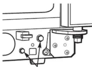
natural_image
Pure mechanical assembly diagram without any text, numbers, or symbols
Roller adjusting screws
These models also have rear adjustable rollers so you can align the refrigerator with your kitchen cabinets. Use a 3/8" hex wrench with extension to turn the screws for the rear rollers—clockwise to raise the refrigerator, counterclockwise to lower it.
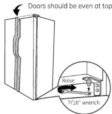
6 LEVEL THE DOORS
Adjust the refrigerator door to make the doors even at the top.
To align:
A Using a 7/16" wrench, turn the door adjusting screw to the right to raise the door, to the left to lower it.
NOTE:
A nylon plug, imbedded in the threads of the pin, prevents the pin from turning unless a wrench is used.
B After one or two turns of the wrench, open and close the refrigerator door and check the alignment at the top of the doors.
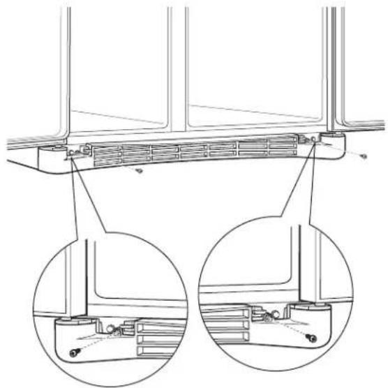
⑦ REPLACE THE BASE GRILLE
Replace the grille by installing the two Phillips head screws.
natural_image
Technical line drawing of a mechanical assembly with two circular insets showing internal components (no text or symbols)
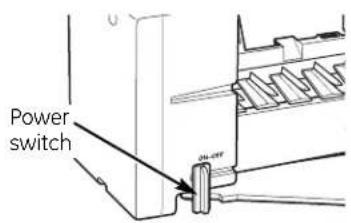
9 START THE ICEMAKER
Set the icemaker power switch to the ON position. The icemaker will not begin to operate until it reaches its operating temperature of 15^ F ( -9^ C) or below. It will then begin operation automatically. It will take 2–3 days to fill the ice bin.
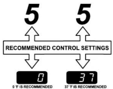
8 SET THE CONTROLS
Set the controls to the recommended setting.
flowchart
graph TD
    A["5"] --> B["RECOMMENDED CONTROL SETTINGS"]
    C["5"] --> D["RECOMMENDED CONTROL SETTINGS"]
    B --> E["0 T IS RECOMMENDED"]
    B --> F["37 T IS RECOMMENDED"]
INSTALLING THE WATER LINE (ICEMAKER & DISPENSER MODELS)
BEFORE YOU BEGIN
Recommended copper water supply kits are WX8X2, WX8X3 or WX8X4, depending on the amount of tubing you need. Approved plastic water supply lines are GE SmartConnect™ Refrigerator Tubing (WX08X10002, WX08X10006, WX08X10015 and WX08X10025).
When connecting your refrigerator to a GE Reverse Osmosis Water System, the only approved installation is with a GE RVKit. For other reverse osmosis water systems, follow the manufacturer's recommendations.
If the water supply to the refrigerator is from a Reverse Osmosis Water Filtration System AND the refrigerator also has a water filter, use the refrigerator's filter bypass plug. Using the refrigerator's water filtration cartridge in conjunction with the RO filter can result in hollow ice cubes and slower water flow from the water dispenser.
This water line installation is not warranted by the refrigerator or icemaker manufacturer. Follow these instructions carefully to minimize the risk of expensive water damage.
Water hammer (water banging in the pipes) in house plumbing can cause damage to refrigerator parts and lead to water leakage or flooding. Call a qualified plumber to correct water hammer before installing the water supply line to the refrigerator.
To prevent burns and product damage, do not hook up the water line to the hot water line.
If you use your refrigerator before connecting the water line, make sure the icemaker power switch is in the OFF position.
Do not install the icemaker tubing in areas where temperatures fall below freezing.
When using any electrical device (such as a power drill) during installation, be sure the device is double insulated or grounded in a manner to prevent the hazard of electric shock, or is battery powered.
All installations must be in accordance with local plumbing code requirements.
WHAT YOU WILL NEED
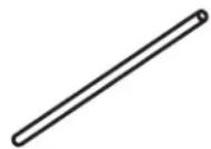
- Copper or GE SmartConnect™ Refrigerator Tubing kit, 1/4" outer diameter to connect the refrigerator to the water supply. If using copper, be sure both ends of the tubing are cut square.
To determine how much tubing you need: measure the distance from the water valve on the back of the refrigerator to the water supply pipe. Then add 8' (2.4 m). Be sure there is sufficient extra tubing (about 8' [2.4 m] coiled into 3 turns of about 10" [25 cm] diameter) to allow the refrigerator to move out from the wall after installation.
GE SmartConnect™ Refrigerator Tubing Kits are available in the following lengths:
2' (0.6 m) - WX08X10002
6' (1.8 m) - WX08X10006
15' (4.6 m) - WX08X10015
25' (7.6 m) - WX08X10025
Be sure that the kit you select allows at least
8' (2.4 m) as described above.
WHAT YOU WILL NEED (CONT.)
NOTE: The only GE approved plastic tubing is that supplied in GE SmartConnect ^™ Refrigerator Tubing kits. Do not use any other plastic water supply line because the line is under pressure at all times. Certain types of plastic will crack or rupture with age and cause water damage to your home.
- A GE water supply kit (containing tubing, shutoff valve and fittings listed below) is available at extra cost from your dealer or from Parts and Accessories, 800.626.2002 (in Canada 1.888.261.3055).
- A cold water supply. The water pressure must be between 20 and 120 p.s.i. (1.4–8.1 bar).
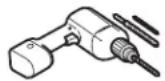
- Power drill.
- 1/2" or adjustable wrench.
- Straight and Phillips blade screwdriver.
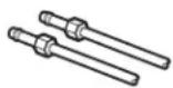
- Two 1/4" outer diameter compression nuts and 2 ferrules (sleeves)—to connect the copper tubing to the shutoff valve and the refrigerator water valve.
OR
- If you are using a GE SmartConnect™ Refrigerator Tubing kit, the necessary fittings are preassembled to the tubing.
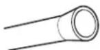
- If your existing copper water line has a flared fitting at the end, you will need an adapter (available at plumbing supply stores) to connect the water line to the refrigerator OR you can cut off the flared fitting with a tube cutter and then use a compression fitting. Do not cut formed end from GE SmartConnect™ Refrigerator tubing.
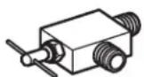
- Shutoff valve to connect to the cold water line. The shutoff valve should have a water inlet with a minimum inside diameter of 5/32" at the point of connection to the COLD WATER LINE. Saddle-type shutoff valves are included in many water supply kits. Before purchasing, make sure a saddle-type valve complies with your local plumbing codes.
Install the shutoff valve on the nearest frequently used drinking water line.
① SHUT OFF THE MAIN WATER SUPPLY
Turn on the nearest faucet long enough to clear the line of water.
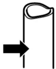
② CHOOSE THE VALVE LOCATION
Choose a location for the valve that is easily accessible. It is best to connect into the side of a vertical water pipe. When it is necessary to connect into a horizontal water pipe, make the connection to the top or side, rather than at the bottom, to avoid drawing off any sediment from the water pipe.
natural_image
Simple line drawing of a bent pipe or tube with an arrow pointing to it (no text or symbols)
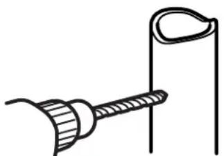
3 DRILL THE HOLE FOR THE VALVE
Drill a 1/4" hole in the water pipe (even if using a self-piercing valve), using a sharp bit. Remove any burrs resulting from drilling the hole in the pipe.
Take care not to allow water to drain into the drill.
Failure to drill a 1/4" hole may result in reduced ice production or smaller cubes.
natural_image
Simple line drawing of a tool with a curved handle and a vertical line, no text or symbols present.
INSTALLING THE WATER LINE (CONT.)
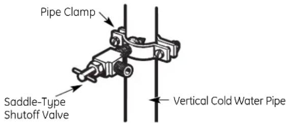
4 FASTEN THE SHUTOFF VALVE
Fasten the shutoff valve to the cold water pipe with the pipe clamp.
NOTE: Commonwealth of Massachusetts Plumbing Codes 248CMR shall be adhered to. Saddle valves are illegal and use is not permitted in Massachusetts. Consult with your licensed plumber.
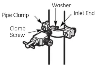
5 TIGHTEN THE PIPE CLAMP
Tighten the clamp screws until the sealing washer begins to swell.
NOTE: Do not overtighten or you may crush the tubing.
6 ROUTE THE TUBING
Route the tubing between the cold water line and the refrigerator.
Route the tubing through a hole drilled in the wall or floor (behind the refrigerator or adjacent base cabinet) as close to the wall as possible.
NOTE: Be sure there is sufficient extra tubing (about 8' [2.4 m] coiled into 3 turns of about 10" [25 cm] diameter) to allow the refrigerator to move out from the wall after installation.
7 CONNECT THE TUBING TO THE VALVE
Place the compression nut and ferrule (sleeve) for copper tubing onto the end of the tubing and connect it to the shutoff valve.
Make sure the tubing is fully inserted into the valve. Tighten the compression nut securely.
For plastic tubing from a GE SmartConnect™ Refrigerator Tubing kit, insert the molded end of the tubing into the shutoff valve and tighten compression nut until it is hand tight, then tighten one additional turn with a wrench. Overtightening may cause leaks.
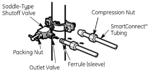
NOTE: Commonwealth of Massachusetts Plumbing Codes 248CMR shall be adhered to. Saddle valves are illegal and use is not permitted in Massachusetts. Consult with your licensed plumber.
8 FLUSH OUT THE TUBING
Turn the main water supply on and flush out the tubing until the water is clear.
Shut the water off at the water valve after about one quart (1 liter) of water has been flushed through the tubing.
natural_image
Simple line drawing of a flower with a curved arrow above it, no text or symbols present.
To complete the installation of the refrigerator, go back to Step 1 in Installing the Refrigerator.

Newer refrigerators sound different from older refrigerators. Modern refrigerators have more features and use newer technology.
Do you hear what I hear? These sounds are normal.
HUMMM... WHOOSH...
■ The new high efficiency compressor may run faster and longer than your old refrigerator and you may hear a high-pitched hum or pulsating sound while it is operating.
■ Sometimes the refrigerator runs for an extended period, especially when the doors are opened frequently. This means that the Frost Guard™ feature is working to prevent freezer burn and improve food preservation.
■ You may hear a whooshing sound when the doors close. This is due to pressure equalizing within the refrigerator.
- You may hear the fans spinning at high speeds. This happens when the refrigerator is first plugged in, when the doors are opened frequently or when a large amount of food is added to the refrigerator or freezer compartments. The fans are helping to maintain the correct temperatures.
■ If either door is open for over 3 minutes, you may hear the fans come on in order to cool the light bulbs.
■ The fans change speeds in order to provide optimal cooling and energy savings.
CLICKS, POPS, CRACKS and CHIRPS
■ You may hear cracking or popping sounds when the refrigerator is first plugged in. This happens as the refrigerator cools to the correct temperature.
■ Electronic dampers click open and closed to provide optimal cooling and energy savings.
■ The compressor may cause a clicking or chirping sound when attempting to restart (this could take up to 5 minutes).
■ The electronic control board may cause a clicking sound when relays activate to control refrigerator components.
■ Expansion and contraction of cooling coils during and after defrost can cause a cracking or popping sound.
- On models with an icemaker, after an icemaking cycle, you may hear the ice cubes dropping into the ice bucket.
WATER SOUNDS
■ The flow of refrigerant through the freezer cooling coils may make a gurgling noise like boiling water.
■ Water dropping on the defrost heater can cause a sizzling, popping or buzzing sound during the defrost cycle.
■ A water dripping noise may occur during the defrost cycle as ice melts from the evaporator and flows into the drain pan.
■ Closing the door may cause a gurgling sound due to pressure equalization.

For additional information on normal icemaker and dispenser operating sounds, see the About the automatic icemaker and About the ice and water dispenser sections.
Before you call for service...

Troubleshooting Tips
Save time and money! Review the charts on the following pages first and you may not need to call for service.
Problem Possible Causes What To Do
| Refrigerator does not operate | Refrigerator in defrost cycle. | ·Wait about 30 minutes for defrost cycle to end. |
| Either or both controls set to OFF. | ·Set the controls to a temperature setting. |
| Refrigerator is unplugged. ·Push the plug completely into the outlet. |
| The fuse is blown/circuit ·Replace fuse or reset the breaker. breaker is tripped. |
| The refrigerator is in ·Unplug the refrigerator and plug it back in. showroom mode. |
| Vibration or rattling (slight vibration is normal) | Rollers need adjusting. | ·See Rollers. |
| Motor operates for long periods or cycles on and off frequently. (Modern refrigerators with more storage space and a larger freezer require more operating time. They start and stop often to maintain even temperatures.) | Normal when refrigerator is first plugged in. | ·Wait 24 hours for the refrigerator to completely cool down. |
| Often occurs when large amounts of food are placed in refrigerator. | ·This is normal. |
| Door left open. | ·Check to see if package is holding door open. |
| Hot weather or frequent door openings. | ·This is normal. |
| Temperature controls set at the coldest setting. | ·See About the controls. |
| Refrigerator or freezer compartment too warm | Temperature control not set cold enough. | ·See About the controls. |
| Warm weather or frequent door openings. | ·Set the temperature control one step colder. See About the controls. |
| Door left open. | ·Check to see if package is holding door open. |
| Frost or ice crystals on frozen food (frost within package is normal) | Door left open. | ·Check to see if package is holding door open. |
| Too frequent or too long door openings. | |
| Divider between refrigerator and freezer compartments feels warm | Automatic energy saver system circulates warm liquid around front edge of freezer compartment. | ·This helps prevent condensation on the outside. |
| Automatic icemaker does not work | Icemaker power switch is in the OFF position. | ·Set the power switch to the ON position. |
| Water supply turned off or not connected. | ·See Installing the water line. |
| Freezer compartment too warm. | ·Wait 24 hours for the refrigerator to completely cool down. |
| Piled up cubes in the storage bin cause the icemaker to shut off. | ·Level cubes by hand. |
| Ice cubes stuck in icemaker. | ·Turn off the icemaker, remove cubes and turn the icemaker back on. |
| Problem Possible Causes | What To Do |
| Frequent "buzzing" sound | Icemaker power switch is in the ON position, but the water supply to the refrigerator has not been connected. | Set the power switch to the OFF position. Keeping it in the ON position will damage the water valve. |
| Ice cubes have odor/taste | Ice storage bin needs cleaning. | Empty and wash bin. Discard old cubes. |
| Food transmitting odor/taste Wrap foods well. to ice cubes. |
| Interior of refrigerator See Care and cleaning. needs cleaning. |
| Small or hollow cubes | Water filter clogged. | Replace filter cartridge with new cartridge or with plug. |
| Slow ice cube freezing | Door left open. | Check to see if package is holding door open. |
| Temperature control not set See About the controls. cold enough. |
| Cube dispenser does not work | Icemaker turned off or water supply turned off. | Turn on icemaker or water supply. |
| An item is blocking or has fallen into the ice chute inside the top door bin of the freezer. | Remove any item that might be blocking, or has fallen into the chute. |
| Ice cubes are frozen to icemaker feeler arm. | Remove cubes. |
| Irregular ice clumps in storage container. | Break up with fingertip pressure and discard remaining clumps. Freezer may be too warm. Adjust the freezer control to a colder setting, one position at a time, until clumps do not form. |
| Dispenser is LOCKED. | Press and hold the LOCK pad for 3 seconds. |
| Water has poor taste/odor | Water dispenser has not been used for a long time. | Dispense water until all water in system is replenished. |
| Water in first glass is warm | Normal when refrigerator is first installed. | Wait 24 hours for the refrigerator to completely cool down. |
| Water dispenser has not been used for a long time. | Dispense water until all water in system is replenished. |
| Water system has been drained. | Allow several hours for replenished supply to chill. |
| Water dispenser does not work | Water supply line turned off or not connected. | See Installing the water line. |
| Water filter clogged. Replace filter cartridge or remove filter and install plug. |
| Air may be trapped in the water system. | Press the dispenser arm for at least two minutes. |
| Dispenser is LOCKED. | Press and hold the LOCK pad for 3 seconds. |
| Water spurting from dispenser | Newly-installed filter cartridge. | Run water from the dispenser for 3 minutes (about one and a half gallons). |
| Water is not dispensed but icemaker is working | Water in reservoir is frozen. | Call for service. |
| Refrigerator control setting is too cold. | Set to a warmer setting. |
| No water or ice cube production | Supply line or shutoff valve is clogged. | Call a plumber. |
| Water filter clogged. Replace filter cartridge or remove filter and install plug. |
| Dispenser is LOCKED. | Press and hold the LOCK pad for 3 seconds. |
| CUBED ICE was selected but CRUSHED ICE was dispensed | Last setting was CRUSHED ICE. | A few cubes were left in the crusher from the previous setting. This is normal. |
Before you call for service...
| Problem Possible Causes What To Do |
| Orange glow in Defrost heater is on. • This is normal.the freezer |
| Refrigerator has odor | Foods transmitting odorto refrigerator. | • Foods with strong odors should be tightly wrapped.• Keep an open box of baking soda in the refrigerator;replace every three months. |
| Interior needs cleaning. • See Care and cleaning. |
| Door not closingproperly sticking or folding | Door gasket on hinge sideover. | • Apply paraffin wax to the face of the gasket. |
| A door bin is hitting a shelfinside the refrigerator. | • Move the door bin up one position. |
| Moisture forms onoutside of refrigerator | Not unusual during periodsof high humidity. | • Wipe surface dry. |
| Moisture collects inside(in humid weather, aircarries moisture intorefrigerator when doorsare opened) | Due to the higher humidity in therefrigerator, you may on occasionexperience fog or small amountsof moisture in the refrigeratorcompartment. | • This is normal and may come and go as different foodloads and environmental conditions change. Wipe drywith a paper towel if desired. |
| Interior light doesnot work | No power at outlet. | • Replace fuse or reset the breaker. |
| Light bulb burned out. | • See Replacing the light bulbs. |
| Water on kitchen flooror on bottom of freezer | Cubes jammed in chute. | • Poke ice through with a wooden spoon. |
| Hot air from bottomof refrigerator | Normal air flow cooling motor.In the refrigeration process, it isnormal that heat be expelled in thearea under the refrigerator. Somefloor coverings are sensitive andwill discolor at these normal andsafe temperatures. | |
| Refrigerator nevershuts off but thetemperatures are OK | Adaptive defrost keepscompressor running duringdoor openings. | • This is normal. The refrigerator will cycle off afterthe door remains closed for 2 hours. |
| Refrigerator beeping | Door open. | • Close door. |
| Actual temperature notequal to Set temperature | Unit just plugged in. | • Allow 24 hours for system to stabilize. |
| Door open for too long. | • Allow 24 hours for system to stabilize. |
| Warm food added to refrigerator. | • Allow 24 hours for system to stabilize. |
| Defrost cycle is in process. | • Allow 24 hours for system to stabilize. |
| Safety Instructions | Operating Instructions | Installation instructions | Troubleshooting Tips | Consumer Support |
| Consumer Support | Troubleshooting Tips | Installation Instructions | Operating Instructions | Safety Instructions |
Notes.
CUSTOMER WARRANTY
(for customers in Canada)
Your refrigerator is warranted to be free of defects in material and workmanship.
| What is covered How Long | Warranted Parts Labour(From Date of Sale) Repair or Replaceat Mabe's Option | |
| Compressor GE Profile: Ten (10) Years GE Profile: Ten (10) Years GE Profile: Five (5) YearsGE and All Other GE and All Other GE and All OtherBrands: One (1) Year Brands: One (1) Year Brands: One (1) Year |
| Sealed System (including evaporator, condenser tubing and refrigerant) | GE Profile: Five (5) YearsGE and All OtherBrands: One (1) Year | GE Profile: Five (5) YearsGE and All OtherBrands: One (1) Year |
| All Other Parts | One (1) Year | One (1) Year |
TERMS AND CONDITIONS:
This warranty applies only for single family domestic use in Canada when the Refrigerator has been properly installed according to the instructions supplied by Mabe and is connected to an adequate and proper utility service.
Damage due to abuse, accident, commercial use, and alteration or defacing of the serial plate cancels all obligations of this warranty.
Service during this warranty period must be performed by an Authorized Mabe Service Agent.
Neither Mabe nor the Dealer is liable for any claims or damages resulting from failure of the Refrigerator or from service delays beyond their reasonable control.
To obtain warranty service, purchaser must present the original Bill of Sale. Components repaired or replaced are warranted through the remainder of the original warranty period only.
This warranty is extended to the original purchaser and any succeeding owner for products purchased for home use within Canada. In home warranty service will be provided in areas where it is available and deemed reasonable by Mabe to provide.
This warranty is in addition to any statutory warranty.
WHAT IS NOT COVERED:
- Owner is responsible to pay for service calls related to product installation and/or teaching how to use the product.
- Damage to finish must be reported within 48 hours following the delivery of the appliance.
• Damage to finish after delivery.
- Improper installation—proper installation includes adequate air circulation to the refrigeration system, adequate electrical, plumbing and other connecting facilities.
- Replacement of house fuses or resetting of circuit breakers.
- Replacement of light bulbs.
- Damage to product caused by accident, fire, floods or acts of God.
- Loss of food due to spoilage.
- Proper use and care of product as listed in the owner's manual, proper setting of controls.
- Product not accessible to provide required service.
- WARRANTOR IS NOT RESPONSIBLE FOR CONSEQUENTIAL DAMAGES.
EXCLUSION OF IMPLIED WARRANTIES—Your sole and exclusive remedy is product repair as provided in this Limited Warranty. Any implied warranties, including the implied warranties of merchantability or fitness for a particular purpose, are limited to one year or the shortest period allowed by law.
IMPORTANT
Keep this warranty and your bill of sale as proof of original purchase and purchase date.
Please have serial number and model number available when calling for service.
Mabe Service is available coast to coast. If further help is needed concerning this warranty, contact:
Manager, Consumer Relations
Mabe Canada Inc., Consumer Service
1 Factory Lane, Suite 310
Moncton, New Brunswick E1C 9M3
1.800.561.3344
Staple your receipt here.
Proof of the original purchase date is needed to obtain service under the warranty.
Refrigerator Warranty. (For customers in the United States)
All warranty service provided by our Factory Service Centers, or an authorized Customer Care® technician. To schedule service, on-line, visit us at ge.com, or call 800.GE.CARES (800.432.2737). Please have serial number and model number available when calling for service.
Staple your receipt here. Proof of the original purchase date is needed to obtain service under the warranty.
For The Period Of: GE Will Replace:
GE and GE PROFILE MODELS:
One Year Any part of the refrigerator which fails due to a defect in materials or workmanship.
From the date of the
During this limited one-year warranty, GE will also provide, free of charge, all labor and original purchase related service to replace the defective part.
Thirty Days
(Water filter, if included)
Any part of the water filter cartridge which fails due to a defect in materials or workmanship.
During this limited thirty-day warranty, GE will also provide, free of charge, a replacement water
From the original filter cartridge.
purchase date of
the refrigerator
GE PROFILE MODELS ONLY:
Five Years Any part of the sealed refrigerating system (the compressor, condenser, evaporator and all connecting tubing) which fails due to a defect in materials or workmanship. During this limited five-year sealed refrigerating system warranty, GE will also provide, free of charge, all labor and related service to replace the defective part in the sealed refrigerating system.
What GE Will Not Cover:
■ Service trips to your home to teach you how to use the product.
■ Improper installation, delivery or maintenance.
- Failure of the product if it is abused, misused, or used for other than the intended purpose or used commercially.
■ Loss of food due to spoilage.
■ Replacement of house fuses or resetting of circuit breakers.
■ Damage caused after delivery.
■ Replacement of the water filter cartridge, if included, due to water pressure that is outside the specified operating range or due to excessive sediment in the water supply.
■ Replacement of the light bulbs, if included, or water filter cartridge, if included, other than as noted above.
■ Damage to the product caused by accident, fire, floods or acts of God.
■ Incidental or consequential damage caused by possible defects with this appliance.
■ Product not accessible to provide required service.
EXCLUSION OF IMPLIED WARRANTIES—Your sole and exclusive remedy is product repair as provided in this Limited Warranty. Any implied warranties, including the implied warranties of merchantability or fitness for a particular purpose, are limited to one year or the shortest period allowed by law.
This warranty is extended to the original purchaser and any succeeding owner for products purchased for home use within the USA. If the product is located in an area where service by a GE Authorized Servicer is not available, you may be responsible for a trip charge or you may be required to bring the product to an Authorized GE Service location for service. In Alaska, the warranty excludes the cost of shipping or service calls to your home.
Some states do not allow the exclusion or limitation of incidental or consequential damages. This warranty gives you specific legal rights, and you may also have other rights which vary from state to state. To know what your legal rights are, consult your local or state consumer affairs office or your state's Attorney General.
SmartWater Filtration System
GWF / HWF Cartridge
This system has been tested according to NSF/ANSI 42/53 for reduction of the substances listed below. The concentration of the indicated substances in water entering the system was reduced to a concentration less than or equal to the permissible limit for water leaving the system, as specified in NSF/ANSI 42/53.*
(100% safety factors built in for unmetered usage)
| Standard No. 42: Aesthetic Effects |
| Parameter USEPA | Influent Effluent % Reduction Min. Required MCL Challenge Concentration Average Maximum Average Minimum Reduction | | | |
| |
| Chlorine — | 2.0 mg/L + _10% | 0.02 ppm | 0.05 ppm | 98.90% | 97.37% | ≥50% |
| T & O | — | — | — | — | — | — | — |
| Particulate** | — | at least 10,000 particles/mL | 3,978 | 7,800 | 98.00% | 96.10% | ≥85% |
| Standard No. 53: Health Effects |
| Parameter | USEPA MCL | Influent Challenge Concentration | Effluent | % Reduction | Min. Required Reduction |
| Average | Maximum | Average | Minimum |
| Turbidity | 1 NTU*** | 11 ±1 NTU*** | 0.07 NTU | 0.1 NTU | 99.71% | 99.59% | 0.5 NTU |
| Cysts | 99.95% Reduction | Minimum 50,000 L | 26 | 55 | 99.97% | 99.95% | >99.95% |
| Lead at pH 6.5 | 15 ppb | 0.15 mg/L ± 10% | 1 ppb | 1 ppb | 99.37% | 99.37% | 0.010 mg/L |
| Lead at pH 8.5 | 15 ppb | 0.15 mg/L ± 10% | 1.8 ppb | 4.3 ppb | 98.8% | 97.13% | 0.010 mg/L |
| Lindane | 0.0002 ppm | 0.002 mg/L ± 10% | 0.00005 ppm | 0.0005 ppm | 91.93% | 91.93% | 0.002 mg/L |
| Atrazine | 0.003 ppm | 0.009 mg/L ± 10% | 0.002 ppm | 0.003 ppm | 76.19% | 64.28% | 0.003 mg/L |
| 2,4-D | 0.100 ppm | 0.210 mg/L ± 10% | 0.042 ppm | 0.090 ppm | 84.89% | 67.63% | 0.07 mg/L |
| Asbestos | 99% | 10' to 10" fibers/L; fibers greater than 10 micrometers in length | 0.32 MFL/ml | 1.2 MFL/ml | 99.95% | 99.82% | 99% |
* Tested using a flow rate of 0.5 gpm; pressure of 60 psig; pH of 7.5 ± 0.5; temp. of 20° ± 2.5°C
** Measurement in Particles/ml. Particles used were 0.5-1 microns
*** NTU=Nephelometric Turbidity units
Operating Specifications
■ Capacity: certified for up to 300 gallons (1135 l); up to six months for models without a replacement filter indicator light; up to one year for models with a replacement filter indicator light
■ Pressure requirement: 40–120 psi (2.8–8.2 bar), non-shock
■ Temperature: 33–100°F (0.6–38°C)
■ Flow rate: 0.5 gpm (1.9 lpm)
General Installation/Operation/Maintenance Requirements
■ Flush new cartridge at full flow for 3 minutes to purge out trapped air.
■ Replace cartridge when flow becomes too slow.
Special Notices
■ Installation instructions, parts and service availability, and standard warranty are included with the product when shipped.
This drinking water system must be maintained according to manufacturer's instructions, including replacement of filter cartridges.
■ Do not use with water that is microbiologically unsafe or of unknown quality without adequate disinfection before or after the system. Systems certified for cyst reduction may be used on disinfected water that may contain filterable cysts.
■ The contaminants or other substances removed or reduced by this water treatment system are not necessarily in your water.
■ Check for compliance with the state and local laws and regulations.
Note that while the testing was performed under standard laboratory conditions, actual performance may vary. Systems must be installed and operated in accordance with manufacturer's recommended procedures and guidelines.
System Tested and Certified by NSF International against ANSI/NSF Standard 42 & 53 for the reduction of:
Standard No. 42: Aesthetic Effects
Chemical Unit
Taste and Odor Reduction
Chlorine Reduction
Mechanical Filtration Unit
Particulate Reduction, Class I
Standard No. 53: Health Effects
Chemical Reduction Unit
Lead and Atrazine Reduction
Lindane and 2,4-D Reduction
Mechanical Filtration Unit
Turbidity Reduction
Cyst and Asbestos Reduction

State of California
Department of Health Services
Water Treatment Device Certificate Number
00 - 1434
Date Issued: May 30, 2000
Date Revised: February 9, 2001
Trademark/Model Designation
Replacement Elements
GE Smart Water Filtration Systems - GWF06 GWF06
GE Smart Water Filtration Systems - GWF GWF
Hotpoint Refrigerator Systems - HWF HWF
Manufacturer: General Electric Appliances
The water treatment device(s) listed on this certificate have met the testing requirements pursuant to Section 116830 of the Health and Safety Code for the following health related contaminants:
Microbiological Contaminants and Turbidity
Cysts (protozoan)
Turbidity
Atrazine
Lindane
2,4-D
Inorganic/Radiological Contamin
Asbestos
Lead
GE Service Protection Plus™
GE, a name recognized worldwide for quality and dependability together with Assurant Solutions, offers you Service Protection Plus™—comprehensive protection on your appliances.*
Benefits Include:
- Prompt, reliable service from GE Authorized Servicers
- Convenient hours designed to suit your busy schedule
• Quality replacement parts
- The dependability of GE, a name recognized and trusted worldwide
- Ask about our interest-free payment plans
With Service Protection Plus you can expect:
- An extended service plan that limits unexpected repair bills
• Service coverage for most major brands
- Unlimited service calls for the length of your contract, or credit toward a replacement product
- Service coverage for covered operating parts and labor on appliances and home electronics that fail during normal single family household use
- Your satisfaction is our goal. We strive to provide you with excellent service in a professional and timely manner.
Place your confidence in GE and call us in the U.S. toll-free at 1.800.626.2224 for more information.
*Most brands covered up to 15 years old in the continental U.S.
SPP is a trademark of General Electric Company.

Cut here
Please place in envelope and mail to:
General Electric Company
Warranty Registration Department
P.O. Box 32150
Louisville, KY 40232-2150
Consumer Product Ownership Registration
Dear Customer:
Thank you for purchasing our product and thank you for placing your confidence in us.
We are proud to have you as a customer!
Follow these three steps to protect your new appliance investment:
1
Complete and mail your Consumer Product Ownership Registration today. Have the peace of mind of knowing we can contact you in the unlikely event of a safety modification.
2
After mailing the registration below, store this document in a safe place. It contains information you will need should you require service. Our service number is 800.GE.CARES (800.432.2737).
3
Read your Owner's Manual carefully. It will help you operate your new appliance properly.
Model Number Serial Number

natural_image
Two identical horizontal lines with evenly spaced tick marks, no text or symbols present
Important: If you did not get a registration card with your product, detach and return the form below to ensure that your product is registered, or register online at ge.com.

Cut here
Consumer Product Ownership Registration

Model Number Serial Number

natural_image
Two identical horizontal lines with tick marks, no text or symbols present
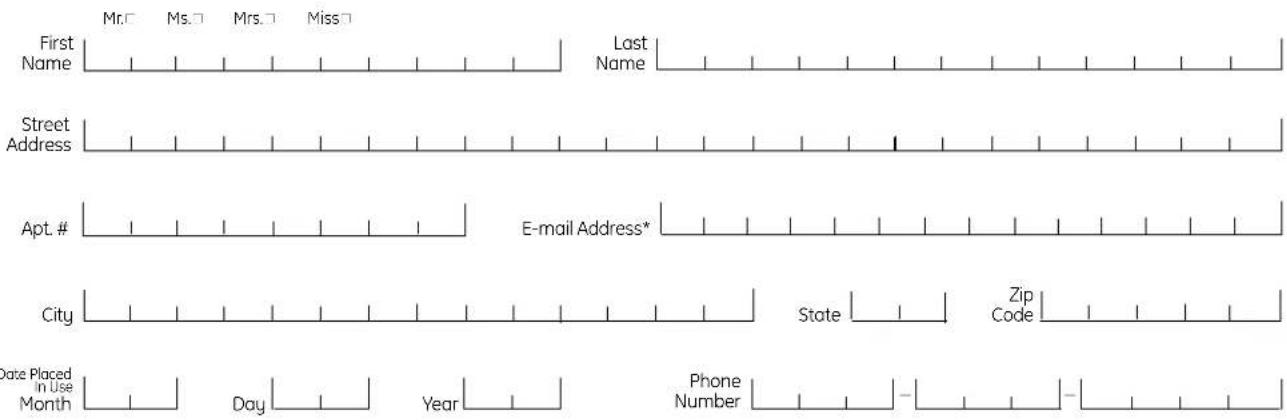

GE Consumer & Industrial Appliances
General Electric Company
Louisville, KY 40225
ge.com
* Please provide your e-mail address to receive, via e-mail, discounts, special offers and other important communications from GE Appliances (GEA).
□ Check here if you do not want to receive communications from GEA's carefully selected partners.
FAILURE TO COMPLETE AND RETURN THIS CARD DOES NOT DIMINISH YOUR WARRANTY RIGHTS.
For information about GEA's privacy and data usage policy, go to ge.com and click on "Privacy Policy" or call 800.626.2224.
| Safety Instructions | Operating Instructions | Installation Instructions | | Consumer Support/Robb |
natural_image
Line drawing of an open refrigerator with a door and drawer, showing no text or symbols
natural_image
Line drawing of a refrigerator drawer with shelves and compartments (no text or symbols)
ExpressThaw™
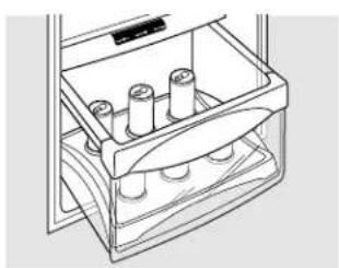
natural_image
Line drawing of a refrigerator drawer with shelves and cylindrical objects (no text or symbols)
ExpressChill™
Utilisation
natural_image
Technical line drawing of a mechanical device with no visible text or symbols
50
natural_image
Technical line drawing of a mechanical device with internal components and mounting brackets (no text or symbols)
natural_image
Technical line drawing of a mechanical component with internal hatched structure (no text or symbols)
natural_image
Illustration of a document with a paper and a ruler, showing no text or symbols
natural_image
Abstract line drawing of a stylized arrow emerging from a rectangular object (no text or symbols)
natural_image
Illustration of stacked documents with a pen and arrow indicating a file or document (no text or symbols present)
Clayette QuickSpace™
natural_image
Line drawing of a rectangular metal cage or rack structure with internal grid lines (no text or symbols)
natural_image
Technical line drawing of a metal grate with a handle and lever mechanism (no text or symbols)
natural_image
Line drawing of a mechanical device with rollers and a lid (no text or symbols)
natural_image
Line drawing of a mailbox with a magnified inset showing its handle (no text or symbols)
natural_image
Diagram of a refrigerator interior showing internal compartments and directional arrows indicating movement (no text or symbols)
natural_image
Line drawing of a refrigerator with three shelves and a door (no text or symbols)
natural_image
Pure technical line drawing of a mechanical component or bracket (no text or symbols)
natural_image
Line drawing of a hand pressing down on a door panel (no text or symbols)
natural_image
Line drawing of a hand holding a card into a door (no text or symbols)
natural_image
Line drawing of a person using a computer to open a device (no text or symbols visible)
natural_image
Line drawing of a hand holding a rectangular object with a triangular symbol on the side (no text or symbols present)
natural_image
Hand pouring liquid into a container with an arrow indicating flow direction (no text or symbols)
Bac de trop-plein
natural_image
Simple line drawing of a curved, multi-layered object with no text or symbols
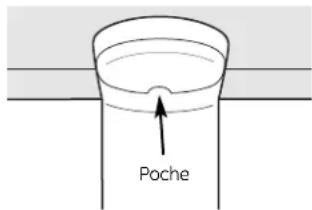
natural_image
Line drawing of a kitchen appliance with a valve and handle (no text or symbols)
natural_image
Simple line drawing of a chair with a seat and arm, no text or symbols present
natural_image
Two men standing beside a large industrial machine with visible control switches and no text or symbols
② ENLEVEZ LA GRILLE DE BASE
natural_image
Technical line drawing of a mechanical assembly with two circular insets showing internal components (no text or symbols)
natural_image
Line drawing of a two-panel cabinet or rack unit (no text or symbols)
natural_image
Diagram of a hand using a tool to lift or lift a curved object, with an arrow indicating the direction (no text or symbols present)
natural_image
Technical line drawing of a mechanical bracket with mounting holes and fasteners (no text or symbols)
natural_image
Line drawing of a double door with shelves inside (no text or symbols)
90°
DÉMÉNAGEMENT DU RÉFRIGÉRATEUR (SUITE)
⑦ ENLEVEZ LA PORTE
DU COMPARTIMENT CONGÉLATION
(suite)
natural_image
Diagram of a refrigerator interior showing arm placement and 90-degree angle (no text or symbols)
natural_image
Diagram of a mechanical clamp or bracket assembly with a handle and lever (no text or symbols)
⑧ ENLEVEZ LA PORTE DU COMPARTIMENT RÉFRIGÉRATION (suite)
natural_image
Line drawing of a refrigerator with open door and shelves, labeled 90° (no text or symbols on the diagram itself)
⑧ ENLEVEZ LA PORTE DU COMPARTIMENT RÉFRIGÉRATION (suite)
natural_image
Mechanical clamp mechanism diagram showing rotational motion with no text or symbols
3 BRANCHEZ LE CORDON DU RÉFRIGÉRATEUR DANS LA PRISE
natural_image
Mechanical assembly diagram showing components and directional arrows (no text or labels)
Vis de réglage
natural_image
Technical line drawing of a mechanical assembly with two circular insets showing internal components (no text or symbols)
⑨ METTEZ EN MARCHE LA MACHINE À GLAÇONS
natural_image
Simple line drawing of a tool with a curved handle and a vertical line, no text or symbols present.
INSTALLATION DE LA CONDUITE D'EAU (SUITE)
4 FIXEZ LE ROBINET D'ARRÊT
natural_image
Line drawing of an open refrigerator with a door and shelf, showing no text or symbols
flowchart
graph TD
    A["Refrigerator"] --> B{Flow Direction}
    B --> C["Refrigerator with Outer Floor"]
    B --> D["Refrigerator with Inside Floor"]
    C --> E["Inner Floor with Horizontal Stresses"]
    D --> F["Inner Floor with Vertical Stresses"]
    E --> G["Refrigerator with Horizontal Stresses"]
    F --> H["Refrigerator with Vertical Stresses"]
    G --> I["Refrigerator with Outer Floor"]
    H --> J["Refrigerator with Inside Floor"]
Cómo funciona
natural_image
Line drawing of a refrigerator drawer with shelves and doors (no text or symbols)
natural_image
Line drawing of a refrigerator drawer with cylindrical objects inside (no text or symbols)
ExpressChill™ (Refrigeración expresa)
Cómo usar
natural_image
Technical line drawing of a mechanical device with no visible text or symbols
92
natural_image
Technical line drawing of a mechanical component with no visible text or symbols
natural_image
Technical line drawing of a mechanical component with meshed surfaces (no text or symbols)
Recipiente inclinable
del congelador
natural_image
Illustration of a stack of books with an arrow pointing to a document (no text or symbols present)
natural_image
Pure diagram of a mechanical component with arrows indicating direction (no text or symbols)
natural_image
Illustration of stacked documents with a pen and arrow indicating a file or document (no text or symbols present)
94
natural_image
Line drawing of a rectangular metal cage with vertical ribs and a flat base (no text or symbols)
natural_image
Technical line drawing of a metal rack with a handle and frame (no text or symbols)
natural_image
Line drawing of a mechanical device with rollers and a lid (no text or symbols)
natural_image
Line drawing of a mailbox with ladder and support structure (no text or symbols)
natural_image
Technical line drawing of a mechanical device with internal components and directional arrows indicating motion (no text or symbols)
natural_image
Line drawing of a multi-tiered storage cabinet or rack unit (no text or symbols)
Bandeja convertible deli
natural_image
Technical line drawing of a mechanical component with an arrow indicating direction (no text or symbols)
natural_image
Line drawing of a person inserting a card into a storage cabinet (no text or symbols)
natural_image
Line drawing of a hand holding a card over a door (no text or symbols)
natural_image
Line drawing of a person using a computer to interact with a device (no text or symbols visible)
natural_image
Line drawing of a hand holding a rectangular object, possibly a cabinet or device, with no visible text or symbols.
natural_image
Simple line drawing of a curved, layered object with no text or symbols
natural_image
Line drawing of a kitchen sink with a pipe and directional arrows indicating movement (no text or symbols)
Compartimento del refrigerador—Luz inferior
natural_image
Simple line drawing of a chair with legs and arm, no text or symbols present
Compartimento del congelador
natural_image
Line drawing of a screwdriver with a magnified view of the tip (no text or symbols)
Destornillador Phillips
natural_image
Two men standing beside a large mechanical device with visible clamps and control bars (no text or symbols)
② REMUEVA LA BASE DE LA PARRILLA
natural_image
Technical line drawing of a mechanical assembly with two circular insets showing internal components (no text or symbols)
natural_image
Diagram of electrical wiring connections with a magnified inset showing cable routing (no text or labels)
natural_image
Line drawing of a two-panel cabinet or rack unit (no text or symbols)
natural_image
Illustration of a hand using a tool to apply material or cleaning on a metal surface (no text or symbols visible)
natural_image
Line drawing of a double-door refrigerator with shelves on the front panel (no text or symbols)
90°
CÓMO MOVER EL REFRIGERADOR (CONT.)
natural_image
Diagram showing a mechanical device with a 90-degree angle indicator, no text or symbols present
natural_image
Diagram of a hand holding a tool with an arrow indicating motion (no text or symbols)
natural_image
Line drawing of a cabinet with shelves and door, labeled 90° (no text or symbols on the diagram itself)
natural_image
Mechanical clamp mechanism diagram showing rotational motion with no text or symbols
3 CONECTE EL REFRIGERADOR
natural_image
Mechanical assembly diagram showing a component with mounting holes and a directional arrow (no text or labels)
natural_image
Mechanical assembly diagram showing components and alignment (no text or labels)
natural_image
Technical line drawing of a mechanical assembly with two circular insets showing internal components (no text or symbols)
natural_image
Simple line drawing of a tool with a curved handle and a vertical rod (no text or symbols)
CÓMO INSTALAR LA TUBERÍA DEL AGUA (CONT.)
4 INSTALE LA VÁLVULA DE APAGADO
natural_image
Diagram showing a flower-like shape being cut with an arrow, no text or symbols present
General Manager, Customer Relations
GE Appliances, Appliance Park
Louisville, KY 40225
Registre su electrodoméstico ge.com
Have a question or need assistance with your appliance? Try the GE Appliances Website, any day of the year! For greater convenience and faster service, you can now download Owner's Manuals, order parts or even schedule service on-line. In Canada: geappliances.ca
Schedule Service
In the U.S.: ge.com
Expert GE repair service is only one step away from your door. Get on-line and schedule your service at your convenience any day of the year! Or call 800.GE.CARES (800.432.2737) during normal business hours.
In Canada, call 1.800.561.3344
Real Life Design Studio
In the U.S.: ge.com
GE supports the Universal Design concept—products, services and environments that can be used by people of all ages, sizes and capabilities. We recognize the need to design for a wide range of physical and mental abilities and impairments. For details of GE's Universal Design applications, including kitchen design ideas for people with disabilities, check out our Website today. For the hearing impaired, please call 800.TDD.GEAC (800.833.4322).
In Canada, contact: Manager, Consumer Relations, Mabe Canada Inc.
Suite 310, 1 Factory Lane
Moncton, N.B. E1C 9M3
Extended Warranties
In the U.S.: ge.com
Purchase a GE extended warranty and learn about special discounts that are available while your warranty is still in effect. You can purchase it on-line anytime, or call 800.626.2224 during normal business hours. GE Consumer Home Services will still be there after your warranty expires. In Canada, call 1.888.261.2133
Parts and Accessories
In the U.S.: ge.com
Individuals qualified to service their own appliances can have parts or accessories sent directly to their homes (VISA, MasterCard and Discover cards are accepted). Order on-line today, 24 hours every day or by phone at 800.626.2002 during normal business hours.
Instructions contained in this manual cover procedures to be performed by any user. Other servicing generally should be referred to qualified service personnel. Caution must be exercised, since improper servicing may cause unsafe operation.
Customers in Canada should consult the yellow pages for the nearest Mabe service center, or call 1.800.661.1616.
If you are not satisfied with the service you receive from GE, contact us on our Website with all the details including your phone number, or write to: General Manager, Customer Relations
GE Appliances, Appliance Park
Louisville, KY 40225
In Canada: geappliances.ca, or write to: Director, Consumer Relations, Mabe Canada Inc.
Suite 310, 1 Factory Lane
Moncton, N.B. E1C 9M3

Register Your Appliance
In the U.S.: ge.com
Register your new appliance on-line—at your convenience! Timely product registration will allow for enhanced communication and prompt service under the terms of your warranty, should the need arise. You may also mail in the pre-printed registration card included in the packing material. In Canada: geappliances.ca