
206E - Remote control toy Vevor - Free user manual and instructions
Find the device manual for free 206E Vevor in PDF.


| Product Type | Remote Control All-Terrain Truck |
| Brand | Vevor |
| Model | 206E |
| Dimensions (approx.) | 300 × 200 × 150 mm |
| Weight (approx.) | 1.2 kg |
| Vehicle Power Supply | Built-in rechargeable battery (Li-ion 7.4 V) |
| Remote Control Power Supply | 2 AA batteries (not included) |
| Motor | Heat-resistant motor with 17-tooth motor gear |
| Control Functions | Forward, backward, left, right |
| Remote Control Range | Approximately 30 meters |
| Operating Frequency | 2.4 GHz |
| Recommended Age | From 3 years under adult supervision (not suitable for under 3 years) |
| Body Material | ABS Plastic |
| Wheel Type | All-terrain rubber tires |
| Maximum Speed (approx.) | 15 km/h |
| Charging Time | Approximately 2 hours |
| Play Time per Charge | Approximately 20 minutes |
| Compliance | FCC (ID: 2AMOZ9300E19880224), WEEE Directive 2012/19/EU |
| Maintenance and Cleaning | Clean with a dry cloth; do not immerse in water |
| Spare Parts and Repairability | Contact customer service via www.vevor.com/support |
| Warranty | Manufacturer's warranty (see Vevor website) |
Frequently Asked Questions - 206E Vevor
User questions about 206E Vevor
0 question about this device. Answer the ones you know or ask your own.
Ask a new question about this device
Download the instructions for your Remote control toy in PDF format for free! Find your manual 206E - Vevor and take your electronic device back in hand. On this page are published all the documents necessary for the use of your device. 206E by Vevor.
USER MANUAL 206E Vevor
Technical Support and E-Warranty Certificate
www.vevor.com/support
AllTerrainRemoteControlOff-RoadTruck
MODEL:206E
We continue to be committed to provide you tools with competitive price. "Save Half", "Half Price" or any other similar expressions used by us only represents an estimate of savings you might benefit from buying certain tools with us compared to the major top brands and does not necessarily mean to cover all categories of tools offered by us. You are kindly reminded to verify carefully when you are placing an order with us if you are actually saving half in comparison with the top major brands.
VEVOR®
TOUGH TOOLS, HALF PRICE
AllTerrainRemote
ControlOff-RoadTruck
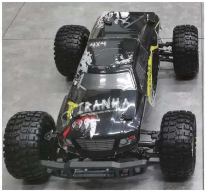
natural_image
Top-down view of a black and yellow IRANHA electric vehicle with four large tires on a reflective floor (no visible text or symbols)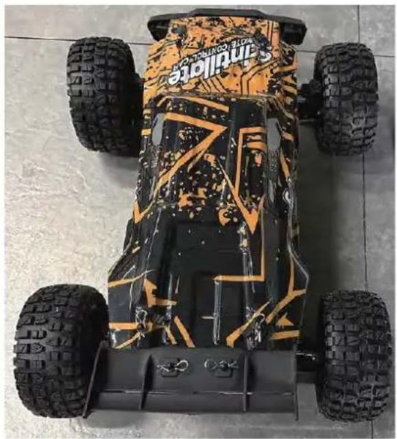
natural_image
Top-down view of a black and orange Honda game vehicle with visible tires and branding (no text or symbols on the vehicle itself)206E
NEEDHELP?CONTACTUS!
Have product questions? Need technical support? Please feel free to contact us:
TechnicalSupportandE-WarrantyCertificate www.vevor.com/support
This is the original instruction, please read all manual instructions carefully before operating. VEVOR reserves a clear interpretation of our user manual. The appearance of the product shall be subject to the product you received. Please forgive us that we won't inform you again if there are any technology or software updates on our product.
PREFACE
To make your experience with this remote control car as easy and convenient as possible, please read the instructions provided before using the product. Enjoy and have fun with the product while keeping the manual for future maintenance and reference.
- In order to protect the legitimate rights and interests of users, please be sure to carefully read the contents of this manual before using this product.
- When using this product, please be sure to strictly observe and perform the requirements which includes but not limited to the instructions and safety guidelines. For any personal injury, accident, property loss, legal dispute, or any other adverse event causing a conflict of interest resulting from the use of the product or any irresistible factors that are in violation of the safety instructions, the user shall bear the related responsibilities and losses.
- Once you start using the product, you are deemed to have read, understood, recommended, and accepted all terms and contents of the instructions (including disclaimers, safety instructions, warning instructions, etc.) included with this product.
- In case you are having challenges on any aspect of the product, may it be operation or maintenance, please contact your local sales agent
PACKAGE CONTENTS
 |  | 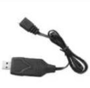 | 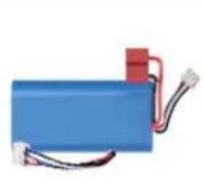 |  |  |
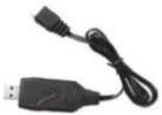
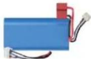
| RC Car | Remote Control | 7.4V USB | 7.4V LI-PO | Product Manual | Accessory package |
CHARGING
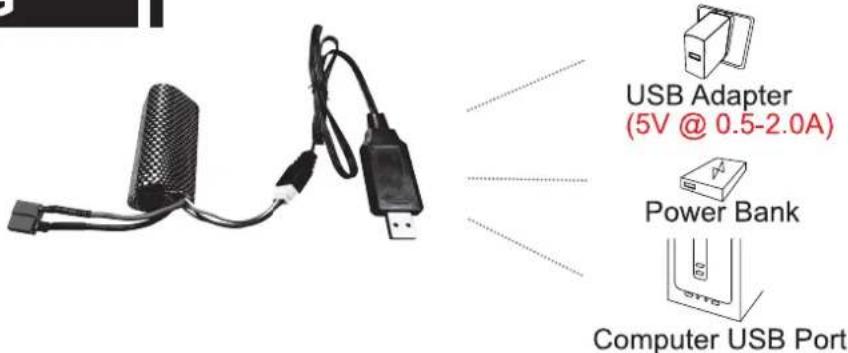
The battery isn't fully charged when it's made. When the car battery low, the car will start the LVC (Low Voltage Cutoff) protection function to protect the battery, the car can only turn, not forward and backward. Please charge the battery.
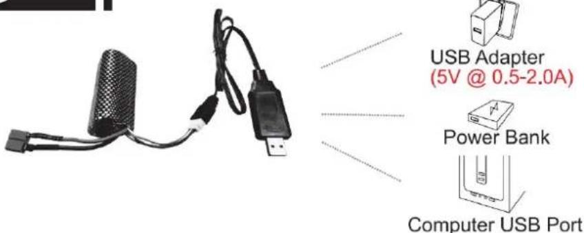
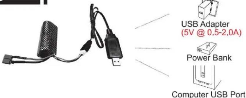
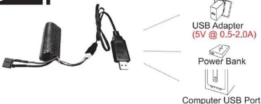
- Plug the USB charging cable into the USB charging port of the computer, power bank or USB adapter (5V@0.5\~2.0A).
- Connect the battery wire to the USB charging cable.
- Charging time: about 250 minutes.
- The green indicator light on the USB charging cable will flash when it is charging and will turn solid once fully charged.
ATTENTION:
- Please keep the battery in sight when charging. DO NOT put the battery on a flammable surface.
- If battery pack and USB charging cable are damaged, immediately stop using it and replace the accessories as soon as possible.
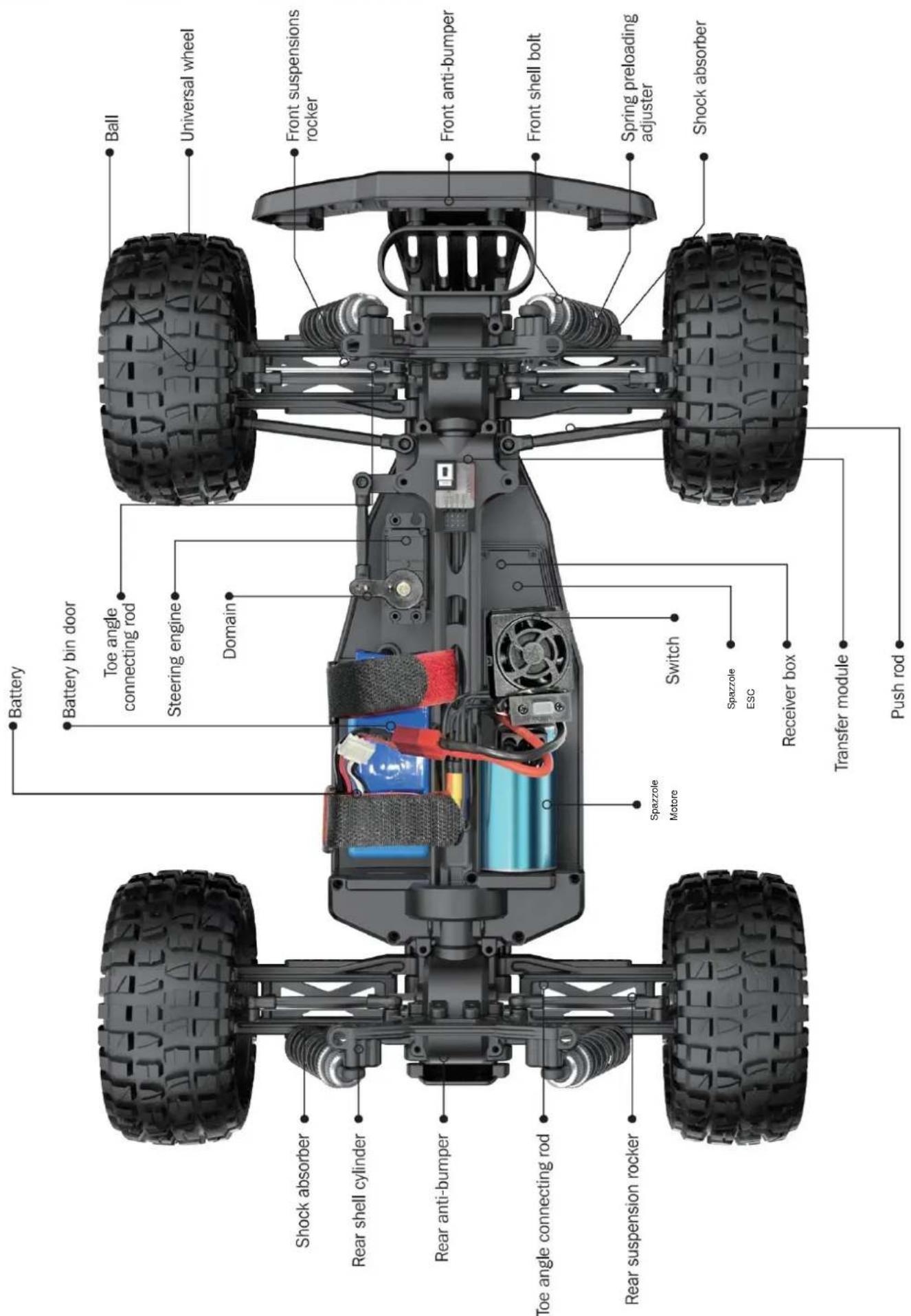
RC CAR'S DETAILS
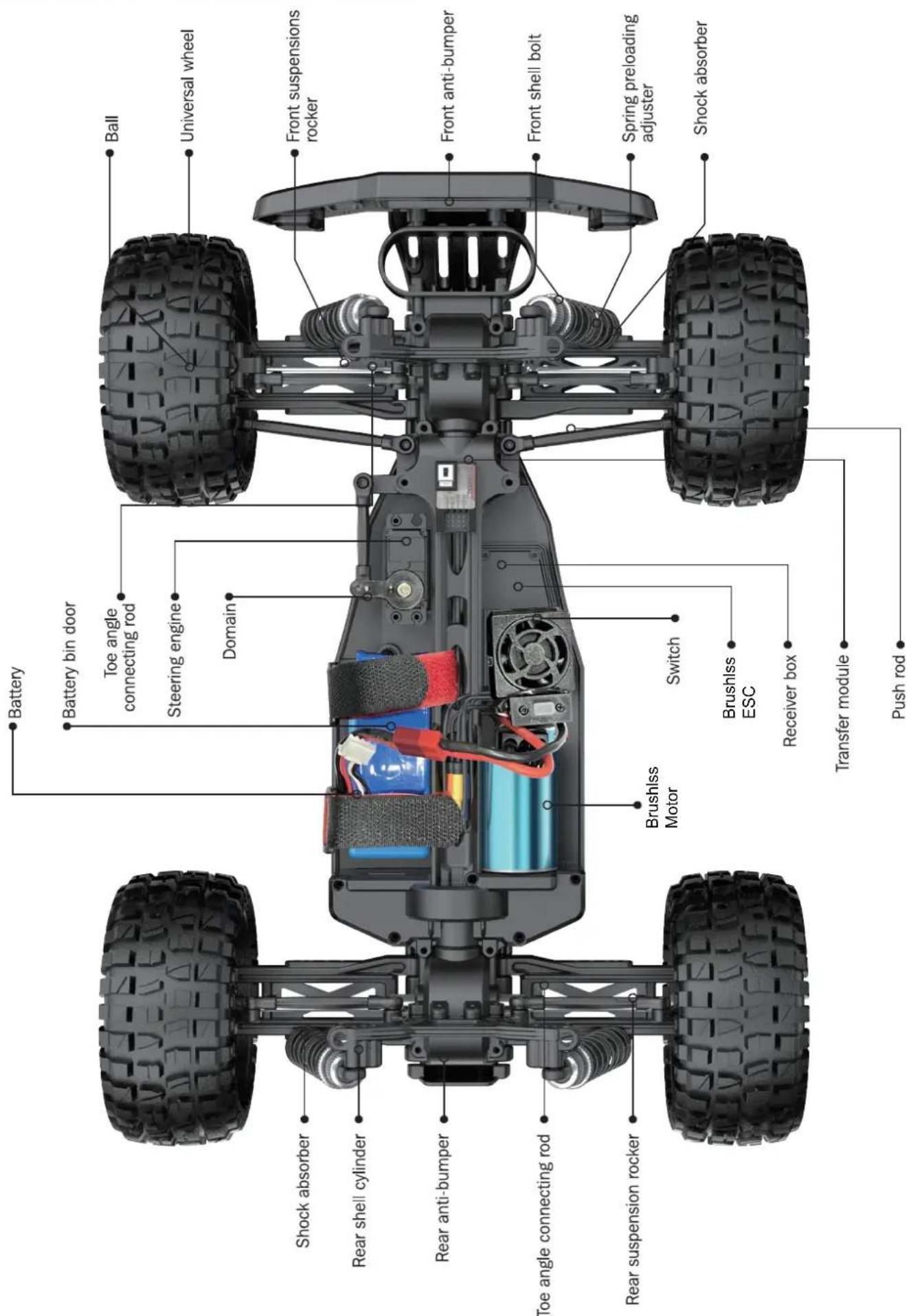
BATTERY INSTALLATION
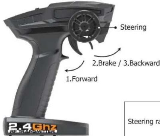
REMOTE CONTROLLER
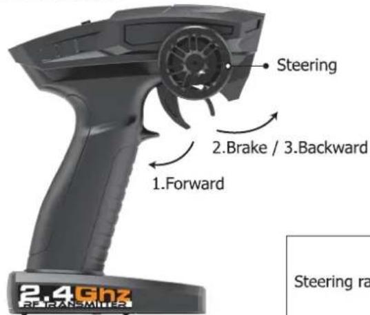
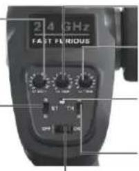
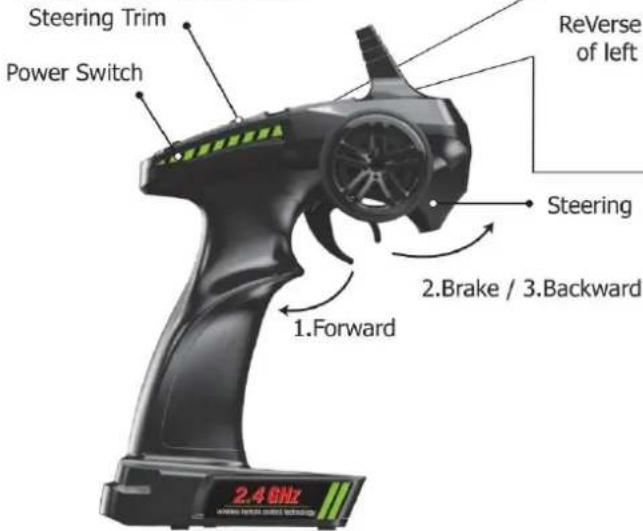
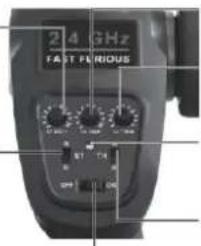
Our company has configured a new remote control for the model, Please ready the operation on the instruction manual carefully. Below is the functions description of this remote control.
■ Remote Control 1
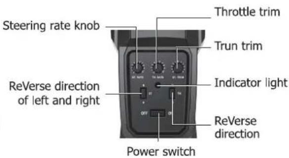
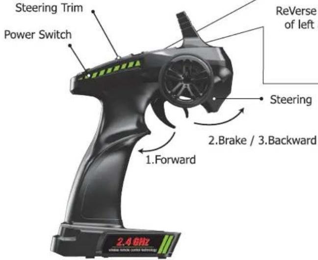
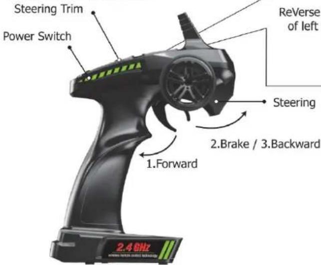
■ Remote Control 2
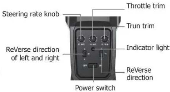
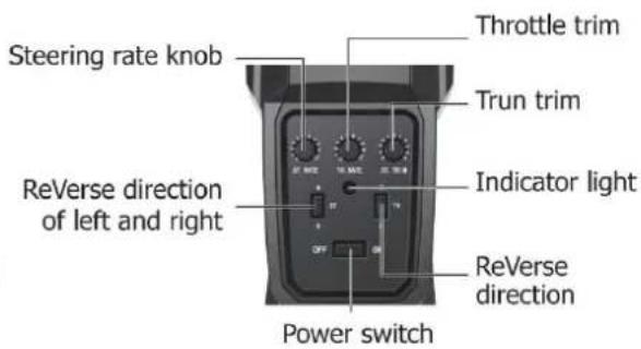
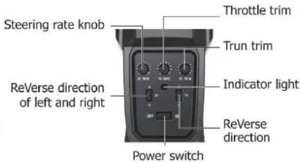
Steering rate knob
ReVerse direction of left and right
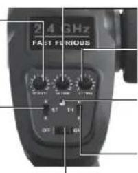
Throttle trim
Trun trim
Indicator light
ReVerse direction
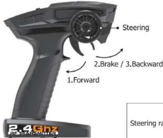
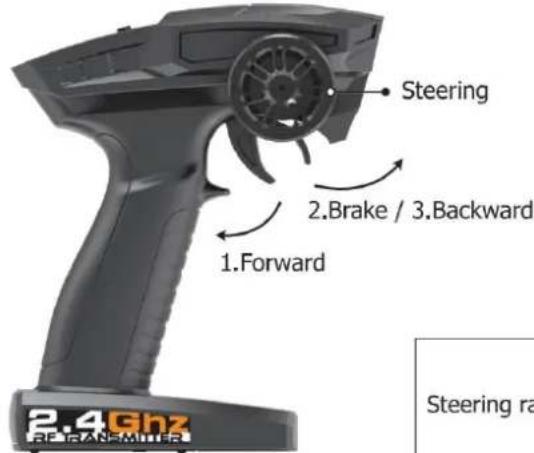
- When the trigger is pulled back, the vehicle advances
- When the vehicle is moving forward, push the trigger forward and the vehicle will brake;
- When the trigger on the remote control returns to the midpoint, push the trigger forward again and the vehicle will retreat.
| LED color/pattern | Name | Hints |
| Red light always on | Normal driving pattern | |
| Red light with slow flash (on at 0.5s/off at 0.5s) | Hint of low power | For more information m please refer to operation of putting new battery into remote on page 6. |
| Red light with quick flash (on at 0.125s/off at 0.125s) | Connect failed/error | If transmitter and receiver are bound unsuccessfully, please close the remote system and restart for recovering normal operation. Please check exceeding scope, low battery or damaged antenna if the connection is failed. |
OPERATION
RC CAR BATTERY
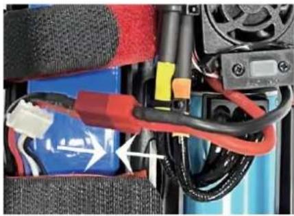
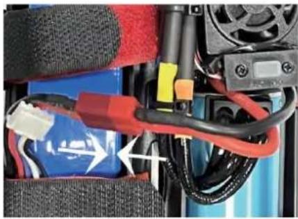
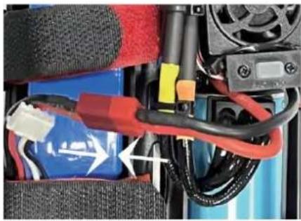
① Take out the clip and open the battery cover.
② Connect the battery outlet to the cable in the battery compartment, then insert the battery to the batter compartment.
③ Close the battery cover and lock it.
If the car will not be used for a long time, make sure to turn it off and remove the battery.

natural_image
Close-up of a battery pack with red and blue components, wiring, and a control panel (no visible text or symbols)REMOTE CONTROL BATTERY
natural_image
Top-down view of a car's front panel showing the left side with a white arrow pointing to the dashboard (no text or symbols visible)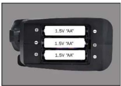
natural_image
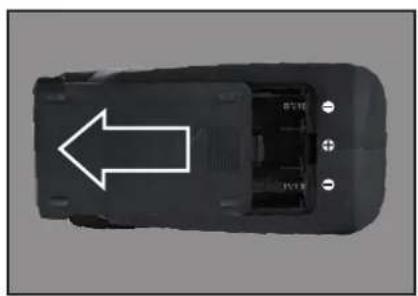
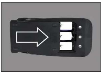
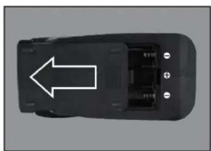
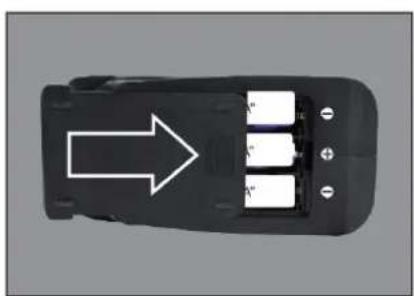
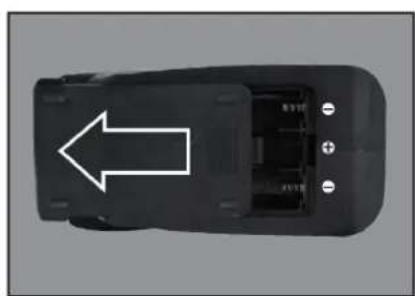
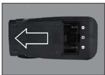
Top-down view of a black automotive battery pack with three white battery cells and an arrow pointing to it (no text or symbols)① Push the battery cover out.
② Insert 3 AA batteries (not included) in the correct direction.
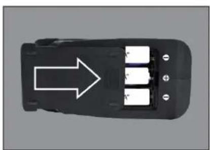
③ Push the battery cover in.
If the remote will not be used for a long time, make sure to turn it off and remove the batteries.
When the battery of the remote control is low, the indicator light of the remote control will flash slowly.
OPERATION
PAIRING
natural_image
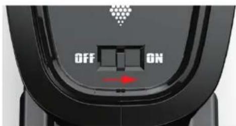
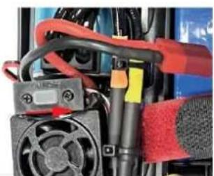
Close-up of electronic components including a fan, resistors, and connectors (no visible text or symbols)Press and hold for 1 second to turn on. Press and hold for 3 seconds to turn off.
① Make sure the battery is charged.
② Insert batteries to the car and the remote.
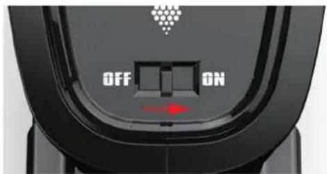
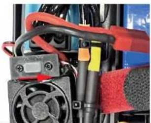
③ Turn on the car power switch and the remote power switch. (DO NOT pull the throttle trigger during pairing)
④ Both will automatically pair. (The remote power indicator and the car power indicator will flash while waiting for the pairing process and will turn solid once pairing has been successful)
FREQUENTLY ASKED QUESTIONS
FORWARD, REVERSE, TURN LEFT, TURN RIGHT
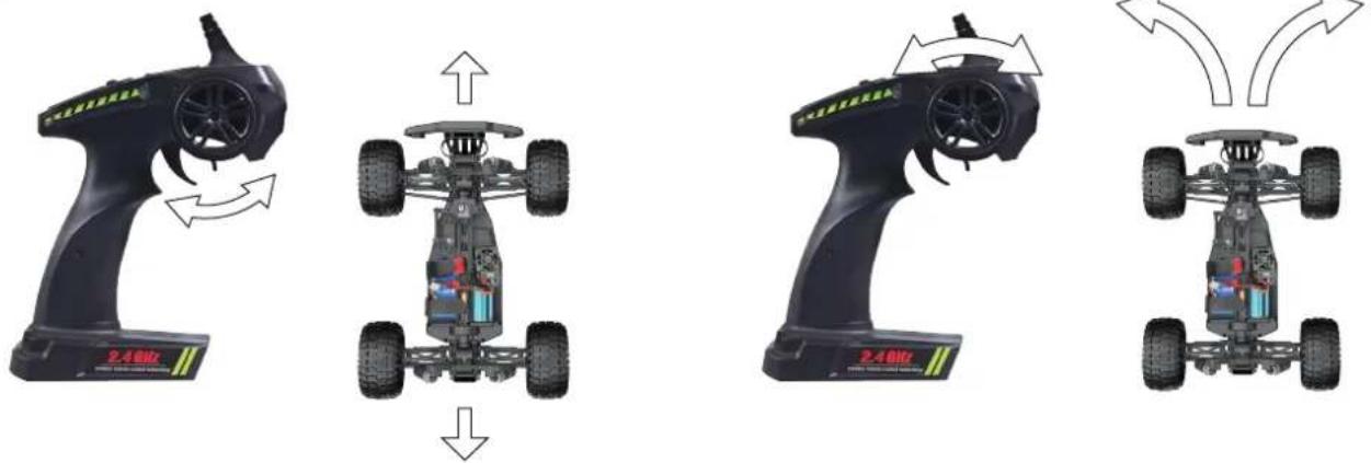
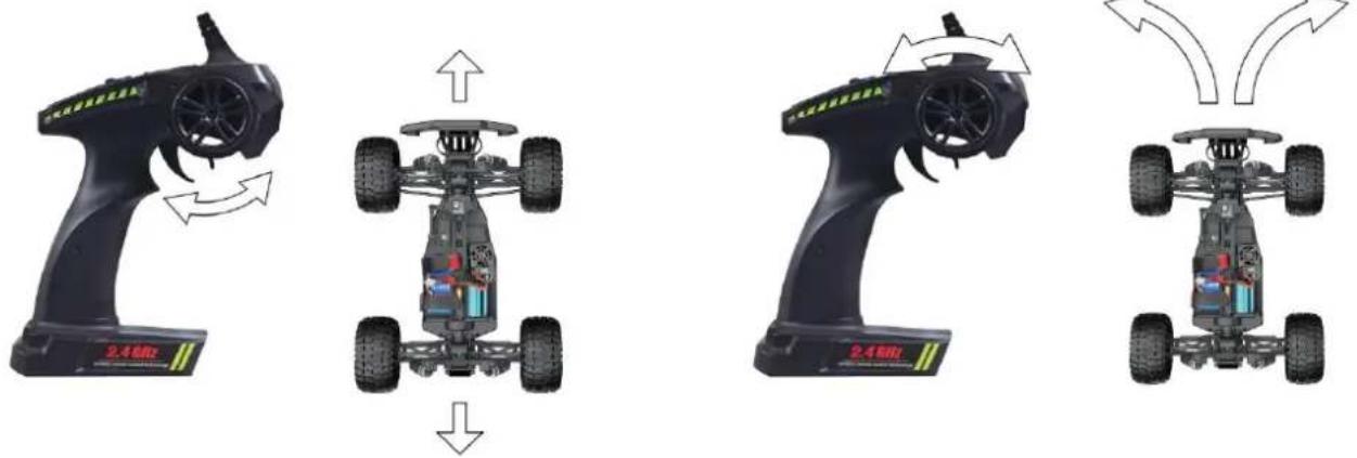
Pull the throttle trigger backward, the car goes forward. Push the throttle trigger forward, the car brakes, then push the throttle trigger forward again, the car goes reverse. (The throttle controls the speed)
Turn the steering control wheel counterclockwise, the car turns left. Turn the steering control wheel clockwise, the car turns right. ( Control the Steering Wheel Rotation Angle can control the degree of turning )
MAXIMUM SPEED CONTROL
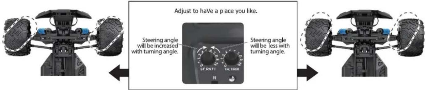
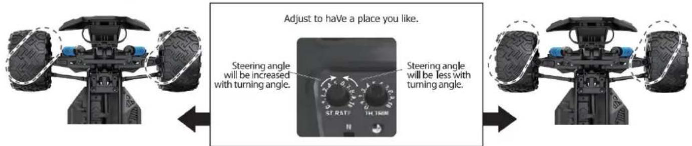
Steering Rate Knob
Use the Steering Rate Knob to adjust direction angle when the steering wheel operated.
Increase the steering angle
Decrease the steering angle
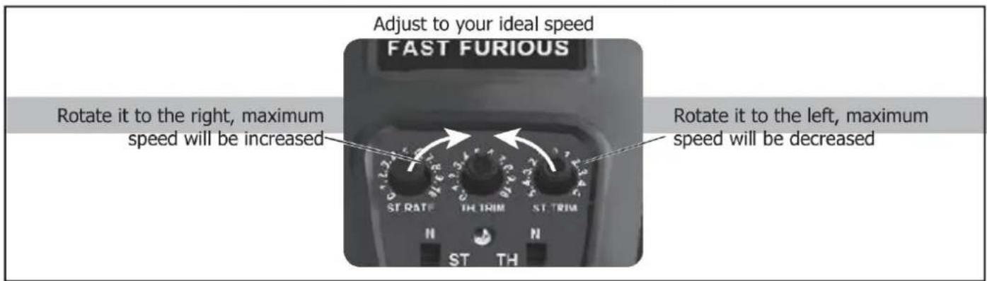
FINE TUNING KNOB OF STEERING
Use throttle to adjust the speed into your ideal one by rotate left or rotate right
Rotate it to the right, maximum speed will be increased
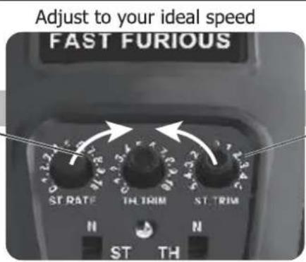
Rotate it to the left, maximum speed will be decreased
| QUESTION | CAUSE | SOLUTION |
| No match or can't control it | 1. The car battery or remote control battery is completely dead2. Out of remote range | 1. Replace charged battery2. Repair and keep in remote distance |
| Can't go forward or reverse | 1. Low battery2. The car shorted out when it got wet3. Poor contact between motor and electronic regulator | 1. Charging2. Let the car dry completely3. Reconnect the connection wire between the motor and the electronic regulator |
| Can't turn left or turn right | 1. The steering angle knob(ST.RATE) is set to minimum2. Low battery3. The car shorted out when it got wet3. Poor contact between steering gear and electronic regulator | 1. Set the steering angle knob (ST.RATE) to maximum2. Charging3. Let the car dry completely4. Reconnect the connection wire between the steering gear and the electronic regulator |
| It won't charge | 1. The output voltage or current of the power supply is too high2. The charging cable or battery is broken | 1. The output voltage and current of the power supply should be 5V0.5~2A2. Contact Customer Service |
| Something's missing or broken | Contact Customer Service | |
| The wheels turn on their own | Pull the throttle trigger during pairing | Repair without pulling the throttle |
SPECIFICATIONS
Motor:
Battery:
Remote frequency:
Remote distance:
Charging mode:
Brushlss Motor
7.4V lithium battery
2.4GHz
100m
USB balance charging cable
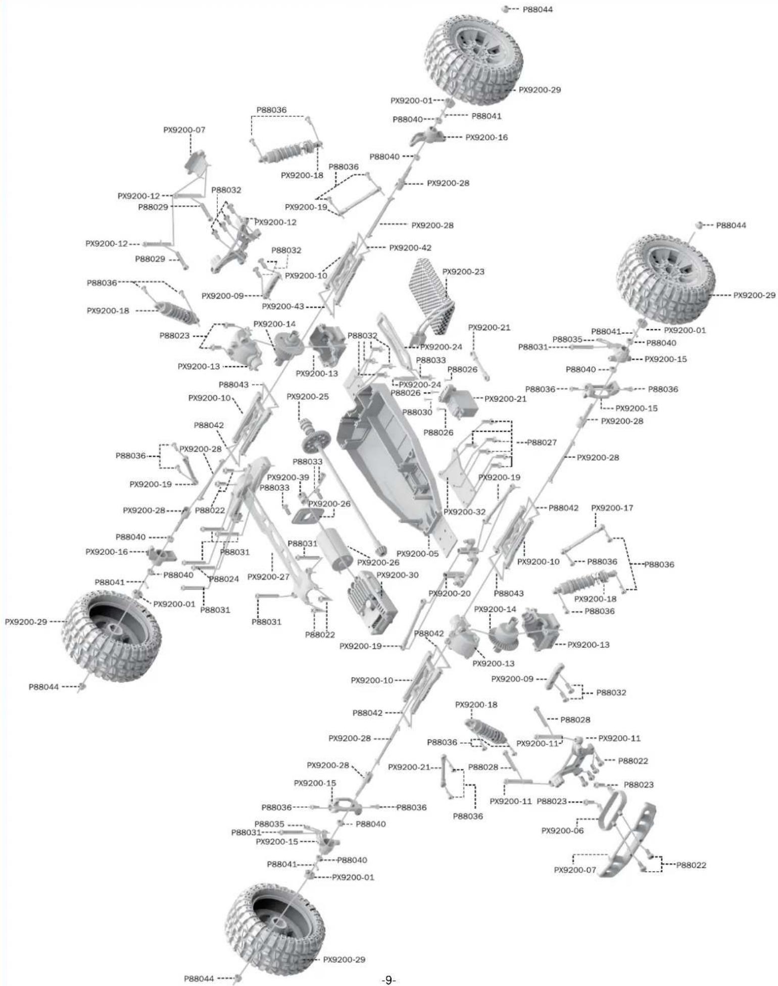
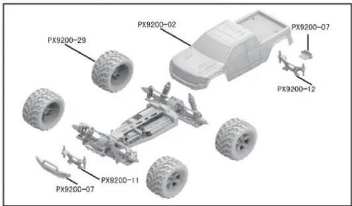
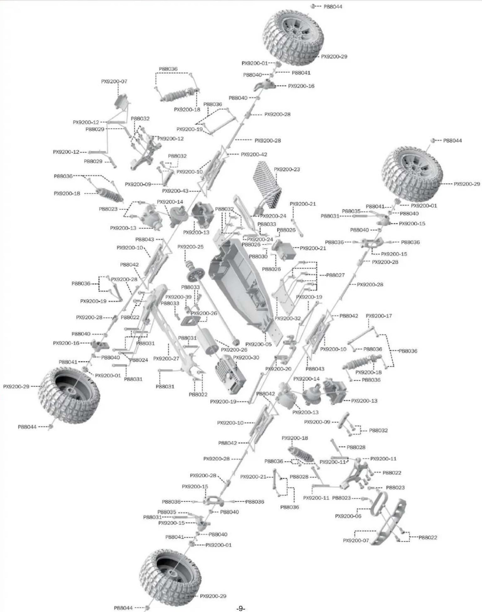
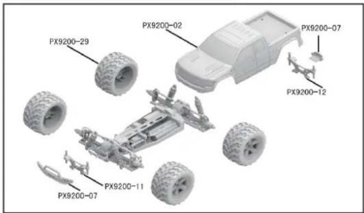
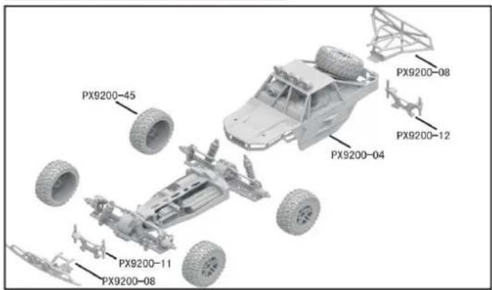
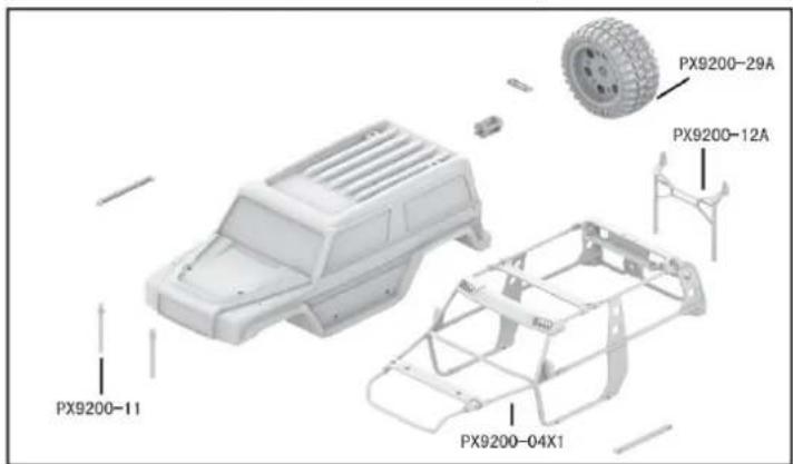
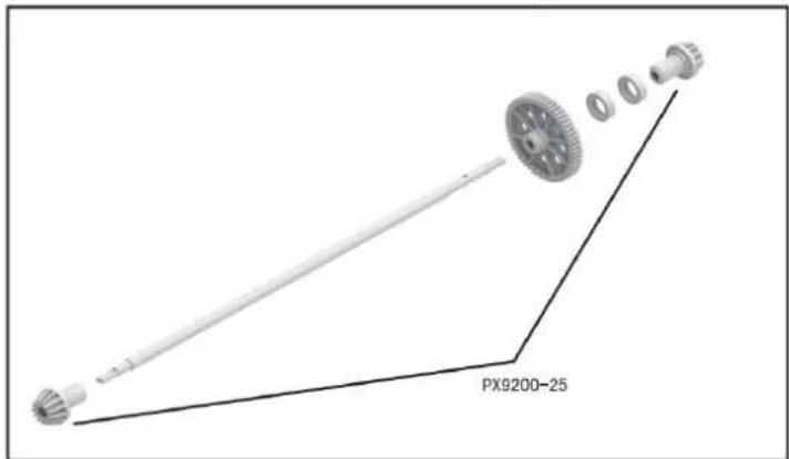
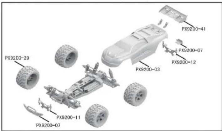
DEVICE EXPLOSION DIAGRAM
9200 ASSEMBLY VIEW

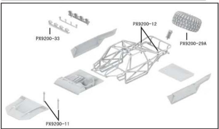
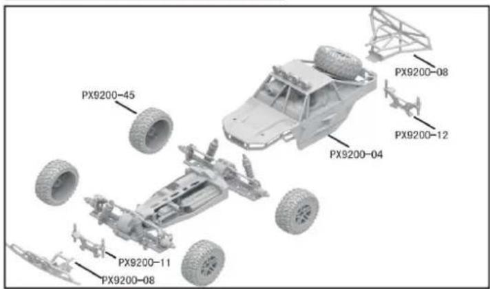
9203 ASSEMBLY VIEW
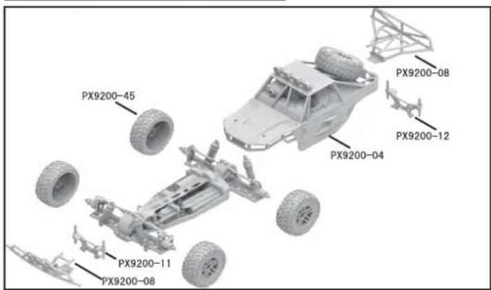
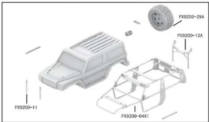
9204 CAR BOBY
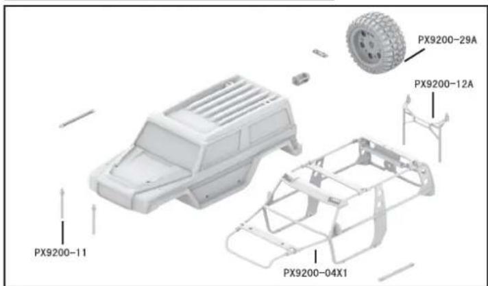
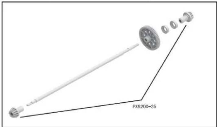
DRIVE AXLE EXPLODED VIEW
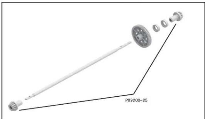
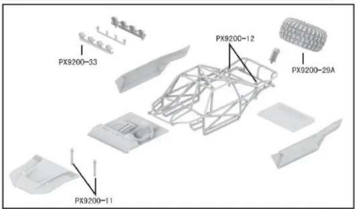
9202 ASSEMBLY VIEW
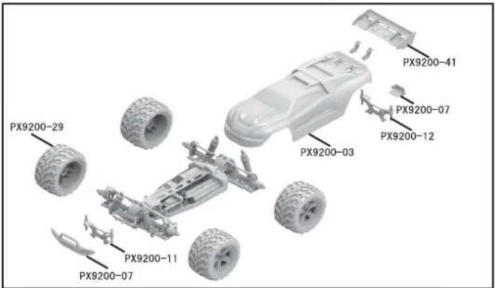
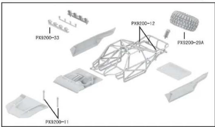
9203 CAR BOBY
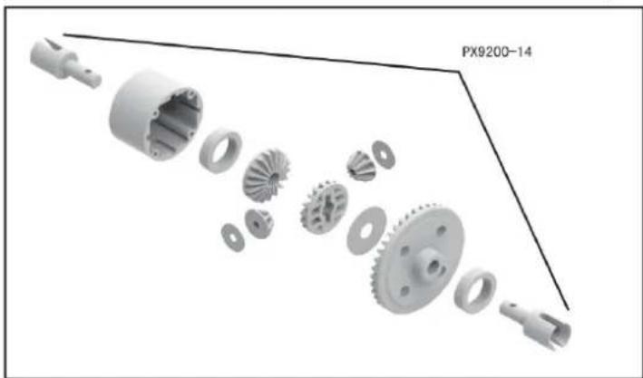
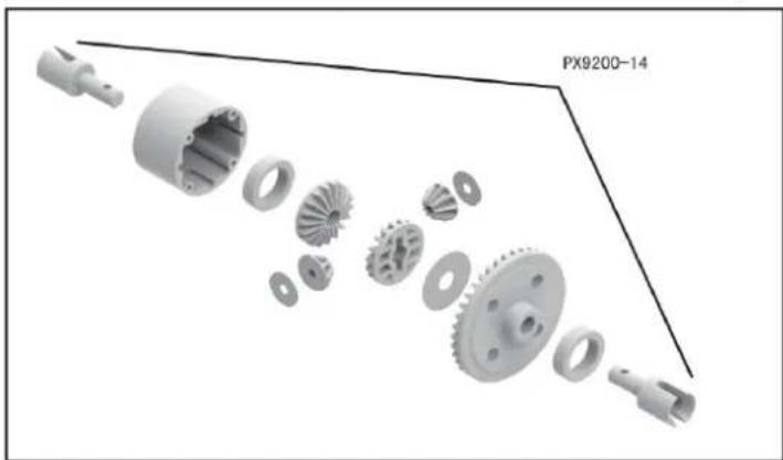
FRONT & REAR DIFFERENTIAL EXPLODED VIEW
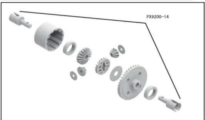
natural_image
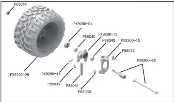
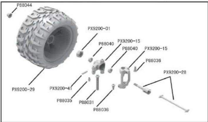
Exploded view diagram of a mechanical gear assembly (no text or symbols)TIRE & WHEEL AXLE EXPLODED VIEW
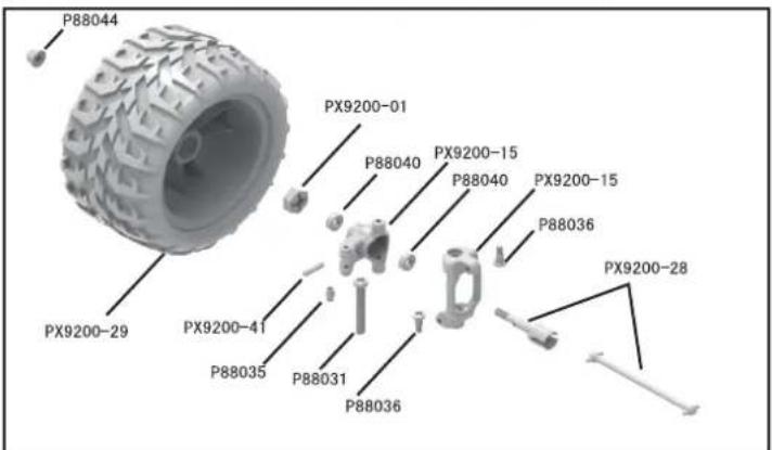
DEVICE EXPLOSION DIAGRAM
RETAIL ACCESSORY VIEW
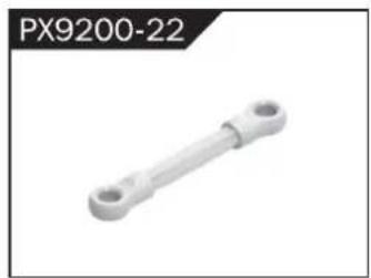
natural_image
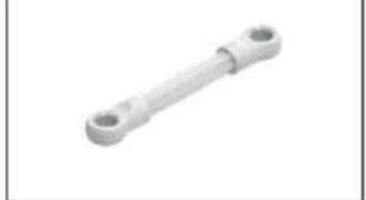
White mechanical component with two circular ends, no visible text or symbolsServo Link
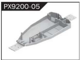
natural_image
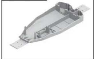
3D model of a mechanical housing component (no text or symbols visible)Chassis
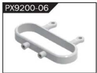
natural_image
3D rendering of a U-shaped mechanical component with mounting holes (no text or symbols visible)Tube-style bumpers

natural_image
Technical line drawing of a mechanical component (no text or symbols)9200-Front/Rear Bumper
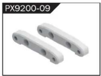
natural_image
Two white plastic mechanical components with circular holes, labeled PX9200-09 (no other text or symbols visible)Tie Bar
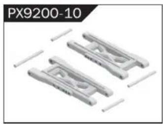
natural_image
Three identical plastic mechanical components with no visible text or symbolsLower Supension Arm
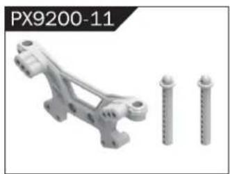
natural_image
Mechanical component with three cylindrical pins, no visible text or symbolsFront Shock Tower and Body Post
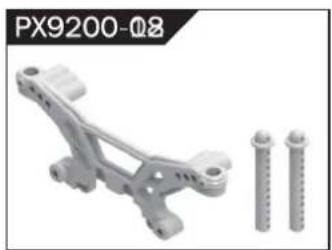
natural_image
Mechanical component with two screws and a bracket, no visible text or symbolsRear Shock Tower and Body Post
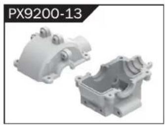
natural_image
Two white plastic mechanical housing components, one open and one closed, with no visible text or symbols.Front/Rear Gear Box
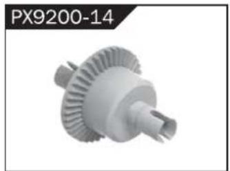
natural_image
3D rendered image of a mechanical gear component (no text or symbols visible)Diff Main Gear Complete
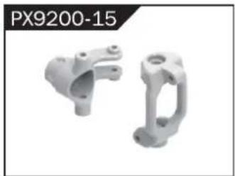
natural_image
Two metallic mechanical components, one with a flanged end and the other a curved bracket (no text or symbols visible)Front Steering Carrier
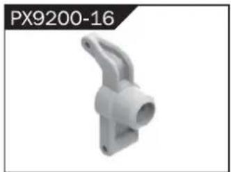
natural_image
White plastic mechanical component with a curved handle and flange (no text or symbols visible)Rear Upright
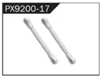
natural_image
Two metallic cylindrical objects with pointed ends, labeled PX9200-17 (no other text or symbols visible)Front/Rear Upper Link
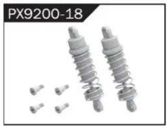
natural_image
Two metallic industrial springs with small bolts and a label PX9200-18 (no other text or symbols)Front/Rear Shock Absorber
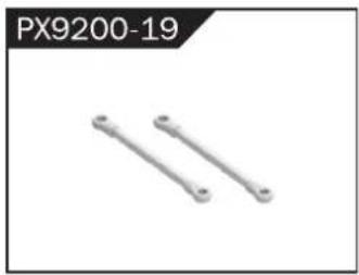
natural_image
Two metallic cylindrical metal rods with circular end caps, labeled PX9200-19 (no additional text or symbols)Steering Link
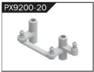
natural_image
3D rendering of a mechanical bracket component (no text or symbols visible)Steering Arm Complete
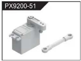
natural_image
3D rendered image of a mechanical component labeled PX9200-51, showing a cylindrical body with mounting holes and a separate elongated shaft (no text or symbols on the object itself)Servo (3 Wire)
RETAIL ACCESSORY VIEW
PX9200-54
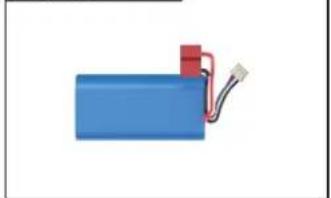
natural_image
Blue battery with red connector and wire, isolated on white background (no text or symbols)LIPO Battery (7.4V 4000MAH)
PX9200-24
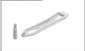
natural_image
Two metallic tool holders, one with a handle and one with a small protrusion (no text or symbols visible)Battery Cover
PX9200-25
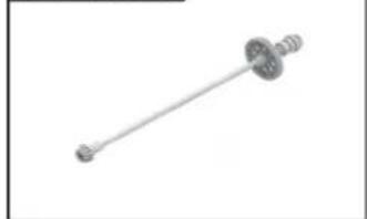
natural_image
Simple line drawing of a mechanical shaft with flanges (no text or symbols)Drive Shaft Assembly
PX9200-50

natural_image
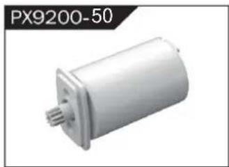
Exterior view of a cylindrical mechanical component with a flanged end and central shaft (no text or symbols visible)Brushless Motor
PX9200-27
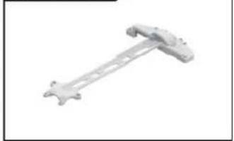
natural_image
Metal mechanical component with a long rod and flange (no text or symbols visible)Motor Layering
PX9200-28
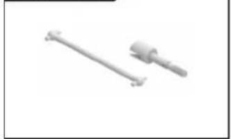
natural_image
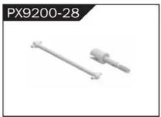
Two metallic mechanical components with threaded ends, shown against a plain background (no text or symbols)Universal Drive Joint
PX9200-29A
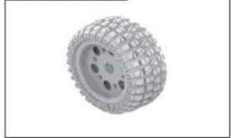
natural_image
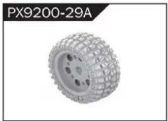
3D rendered image of a wheeled tire or ball component with multiple holes (no text or symbols visible)Vacuum Wheel Complete
PX9200-53
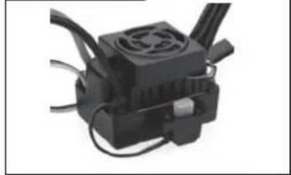
natural_image
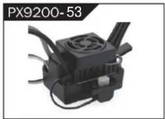
Close-up of a black industrial electrical connector with cooling fan and wiring (no visible text or symbols)ESC
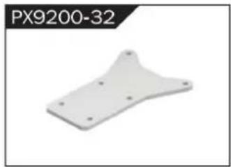
PX9200-32
natural_image
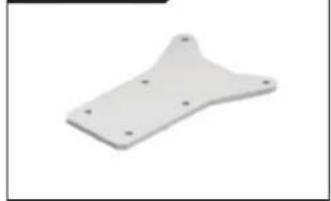
White plastic metal plate with four mounting holes (no text or symbols visible)Chassis Sheet Steel
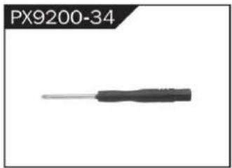
PX9200-34
natural_image
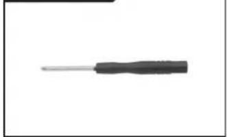
Close-up of a black screwdriver with a metallic tip (no text or symbols visible)3MM Crosstip Screwdrivers
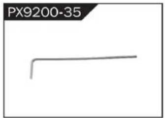
PX9200-35
natural_image
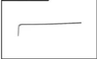
Simple gray line drawing of a right angle on white background (no text or symbols)2MM Hexagon Wrench
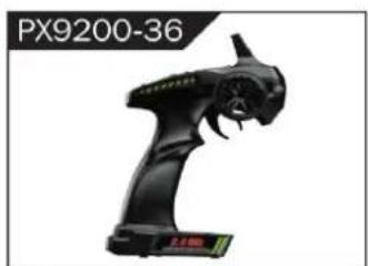
PX9200-36

natural_image
Black handheld electronic device with a stylized face and control panel (no visible text or symbols)I 2.4G Transmitter for all
PX9200-37
natural_image
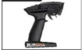
Black handheld device with control panel and handle (no visible text or symbols)II 2.4G Transmitter for all
PX9200-37
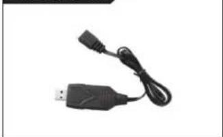
natural_image
Close-up of a black USB and cable connector (no text or symbols visible)7.4V-USB
PX9200-37A
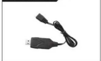
natural_image
Black USB plug with black cable, no visible text or symbols11.1V-USB
PX9200-38
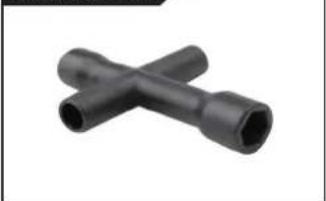
natural_image
Two black X-shaped pipe fittings (no text or symbols visible)Socket Wrench
PX200E-04
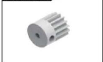
natural_image
3D rendering of a white mechanical gear or rotor component with evenly spaced teeth (no text or symbols visible)PX200E-05
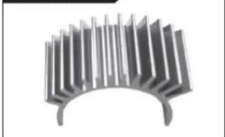
natural_image
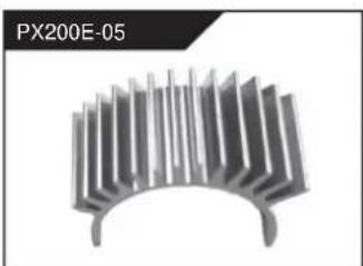
3D rendering of a metallic heat sink or cooling element with radial fins (no text or symbols)Motor Gear(17t) Motor Heat Proof
Cover
RETAIL ACCESSORY VIEW
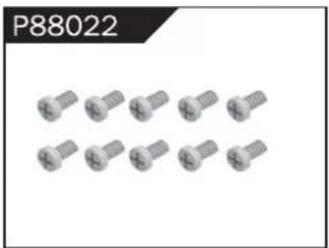
natural_image
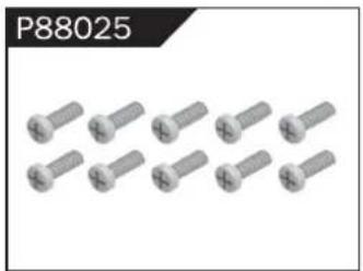
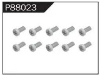
Close-up of multiple metallic screw fasteners arranged in two rows (no text or symbols visible)Φ2.6*7PB Round Head Screw
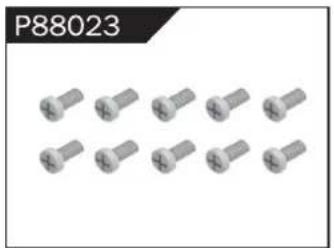
natural_image
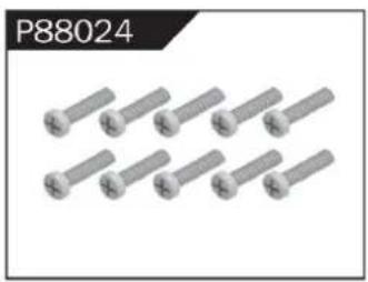
Close-up of ten metallic screw heads arranged in two rows (no text or symbols visible)Φ2.6*10PB Round Head Screw
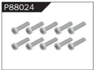
natural_image
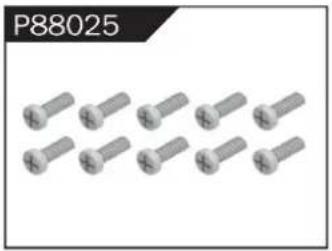
Group of eight identical metallic bolts arranged in two rows (no text or symbols visible)Φ2.6*30PB Round Head Screw
natural_image
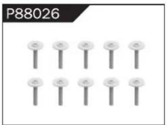
Group of metallic screw-like components arranged in two rows (no text or symbols visible)Φ3*12 Round Head Screw
natural_image
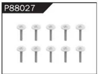
Grid of nine identical pin icons arranged in two rows (no text or symbols)Φ2.3*10PB Screw
natural_image
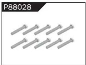
Grid of nine identical screw-like pins arranged in two rows (no text or symbols)Φ2.6*12PB Screw
natural_image
Close-up of multiple gray screwdrivers arranged in a row (no text or symbols visible)Φ1.7*8PB Screw
natural_image
Row of metallic screwdrivers arranged in two rows (no text or symbols visible)Φ2*8PB Screw
natural_image
Grid of metallic cylindrical pins arranged in three rows (no text or symbols visible)Φ2.3*14PB Screw
natural_image
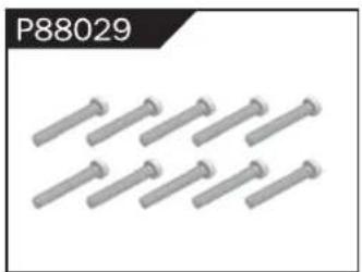
Grid of nine identical metallic cylindrical pins arranged in two rows (no text or symbols)Φ2.6*14PB Screw
natural_image
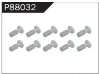
Row of eight identical screw-like mechanical parts, no text or symbols visibleΦ2.6*10 Flattened Head Screw
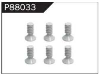
natural_image
Six metallic screw head designs arranged in two rows (no text or symbols visible)Φ3*8 Flattened Head Machine Screw
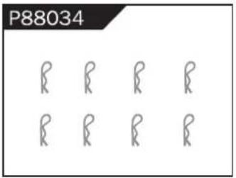
Body Clip
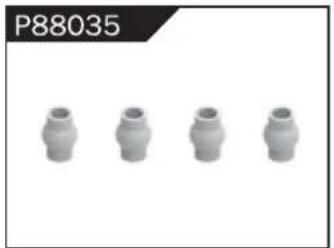
natural_image
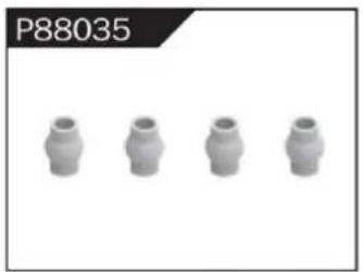
Four identical cylindrical mechanical components arranged horizontally (no text or symbols visible)Hollow Ball Connectors
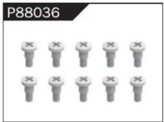
natural_image
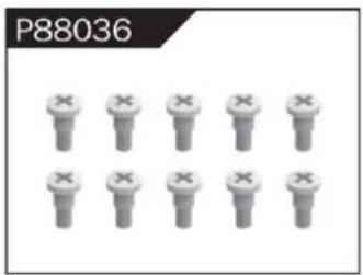
Grid of identical mechanical components with 'X' marks, no text or symbols presentStep Screw
natural_image
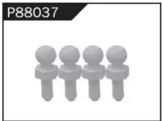
Four stylized human figures in a row, no text or symbols presentΦ4.8 Ball Head
natural_image
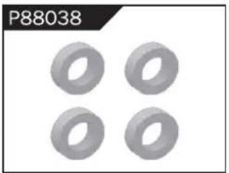
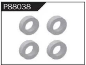
Four identical gray toroidal shapes arranged in a 2x2 grid (no text or symbols)Φ10*15*4 Ball Bearing
natural_image
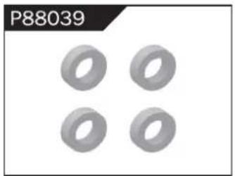
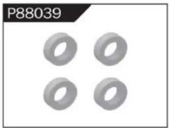
Four identical gray ring-shaped objects arranged in a 2x2 grid (no text or symbols)Φ8*10*3 Ball Bearing
natural_image
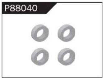
Four identical gray ring-shaped objects arranged in a 2x2 grid (no text or symbols)Φ5*9*3 Ball Bearing
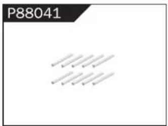
Φ1.5*10 Wheel Hex Pin c
natural_image
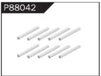
Pure diagram of eight parallel cylindrical rods without any text or symbolsΦ2.5*26.5 Steering Pin B
natural_image
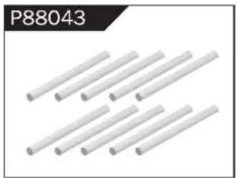
Close-up of multiple white cylindrical rods arranged diagonally (no text or symbols visible)Φ3*48 Front/Rear Lower Suspension Pin A
natural_image
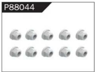
Grid of 12 identical mechanical pipe fitting units (no text or symbols visible)Nylor Nut M4
natural_image
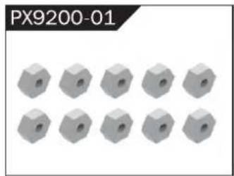
Grid of 12 gray hexagonal blocks with circular holes, labeled PX9200-01 (no other text or symbols)Wheel Hex
WARNINGS
- According to the instructions provided on the manual. Some part needs to be assembled and adjusted by adults.
- Please use under the guidance of an adult.
- Please promptly put away the packing materials so as not to cause harm to children.
- Do not operate on a location where water is trapped or under the rain. Parts of the product may malfunction if exposed to water.
- Do not touch the rotating wheel to avoid injury.
- The product contains small parts that may pose a risk of ingestion or suffocation.
- To remotely control the product on the road or in a crowd to avoid accidents.
- It is necessary to periodically check the charging USB cable, plug, housing and other components, and immediately unplug if found to be damaged.
- This product can only use the factory configured USB cable to charge the product battery.
- USB cable, battery box, and battery must be inserted into the same specified power supply as the product symbol.
- The USB charging cable and the battery is not a toy.
- Disconnect the rechargeable USB cable before cleaning the toy.
- If you observe electrical charges during product usage, turn off the device immediately.
- When installing or replacing the battery, pay attention to the correct polarity of the battery.
- The remote control car uses a 7.4V Lithium battery.
- It is strictly prohibited do the following actions such as but not limited to disassemble, modify, crash, puncture, drop, throw in a fire or any other means of causing damage to the product to avoid harm to the user and other participants.
- Do not expose the battery to prolonged exposure to sunlight to prevent danger.
- It is advisable to store the battery at a temperature below 30^ C. Do not store it in a place with heat, high temperature, or humidity to avoid danger.
- Non-rechargeable batteries cannot be charged.
- When charging a rechargeable battery, adult supervision is required.
- The rechargeable battery should be removed from the toy before charging.
- Do not mix old and new or different types of batteries.
- Only use the USB cable configured by this product when charging the battery.
- Do not disassemble the battery or modify the battery to avoid risk of fire or explosion.
- After the battery is used, it should be taken out of the remote control car. After cooling the battery, you can then charge it and placed it on a safe location. Unplug the battery outlet from the USB charging cable when not in used and disconnect the power line.
- Stop using the battery as soon as it gives a foul smells or suddenly becomes hot, deformed, discolored, or otherwise abnormal during use or charging.
- After the battery of the remote controller runs out, battery temperature is usually high and would recommend to wait for
30 minutes before charging the battery again. Otherwise, it may damage the battery. - Drained batteries should be removed immediately.
- Do not cause the electrical supply of the wiring port to short circuit.
- If you do not use the product for a long time, remove the batteries of the remote control car and remote control.
- instructions contains important product information, please give time to read for better product experience.
GENERAL INFORMATION
CAN NMB-3 (B)
RF Exposure
Radiation Exposure Statement:
This equipment complies with IC radiation exposure limits set forth for an uncontrolled environment. This equipment should be installed and operated with minimum distance 20cm between the radiator & your body.
BATTERY WARNING:
- Failure to follow all the instructions may result in serious injury, irreparable damage to the battery and may cause a fire, smoke or explosion.
- Always check the battery's condition before charging or using it.
- Replace the battery if damaged, gives a foul odor or show signs of overheating, discoloration, deformation and leakage.
- Never use anything other than the approval charger the battery. Always use a balancing charger for battery. It is recommended that you do not to use any other charger than the one provided with the product.
- The battery temperature must never exceed 60°C (140°F) otherwise the battery could be damaged or ignite.
- Never charge on a flammable surface, near flammable products or inside a vehicle (perferably place the battery in a non-flammable and nonconductive container).
- Never leave the battery unattended during the charging process. Never disassemble or modify the housing's wiring, or puncture the cells. Always ensure that the charger output voltage corresponds to the voltage of the battery. Do not overcharge the batter that may cause short circuit.
- Never expose the battery to moisture or direct sunlight, or store it in a place where temperatures could exceed 60^ C (car in the sun, for example).
- Always keep it out of reach from children.
- Improper battery use may result in a fire, explosion or other hazard.
- Non-rechargeable batteries are not be charge again. Rechargeable batteries are only to be charged with the supervision of an adult.
- Different types of batteries or new or used batteries which are different are not be mixed.
- Batteries are to be inserted with the correct polarity.
- The supply terminal should be used well to avoid short circuit. Examination of the transformer and battery charger regularly is encouraged to check any damage in the cord, plug, enclosure and other parts. If damage is observed, it must not be used until it has been repaired.
- The packaging has to be kept since it contains important information.
- The toy is only to be connected to Class II equipment bearing the symbol.
AllTerrainRemoteControlOff-RoadTruck
FCCInformation ((FCCID:2AMOZ9300E19880224)):
CAUTION: Changes or modifications not expressly approved by the party responsible for compliance could void the user's authority to operate the equipment!
This device complies with Part 15 of the FCC Rules. Operation is subject to the following two conditions:
1) This product may cause harmful interference.
2) This product must accept any interference received, including interference that may cause undesired operation.
WARNING: Changes or modifications to this product not expressly approved by the party responsible for compliance could void the user's authority to operate the product.
Note: This product has been tested and found to comply with the limits for a Class B digital device pursuant to Part 15 of the FCC Rules. These limits are designed to provide reasonable protection against harmful interference in a residential installation.
This product generates, uses, and can radiate radio frequency energy, and if not installed and used in accordance with the instructions, it may cause harmful interference in radiocommunications. However, there is no guarantee that interference will not occur in a particular installation. If this product does cause harmful interference to radio or television reception, which can be determined by turning the product off and on, the user is encouraged to try to correct the interference by one or more of the following measures.
- Reorient or relocate the receiving antenna.
- Increase the distance between the product and the receiver.
- Connect the product to an outlet on a circuit different from that to which the receiver is connected.
- Consult the dealer or an experienced radio/TV technician for assistance.
CorrectDisposal
This product is subject to the provision of european Directive 2012/19/EU. The symbol showing a wheelie bin crossed through indicates that the product requires separate refuse collection in the European Union. This applies to the product and all accessories marked with this symbol. Products marked as such may not be discarded with normal domestic waste, but must be taken to a collection point for recycling electrical and electronic devices.

WARNING:
CHOKING HAZARD-Small parts. Not for children under 3 years.
Children should only use it under adult supervision. Never play alone in the water or by the pond.

AVERTISSEMENT:
Manufacturer: SHANTOU PENGXIANG TOYS FACTORY.
Address: City, GuangDong Province, CHINA Pengxiang Building, Gangxia Road, Bumei Industrial Zone, ChenghaiArea, Shantou
C/O YH Consulting Limited Office 147, Centurion House, London Road, Staines-upon-Thames, Surrey, TW18 4AX
ImportedtoAUS:SIHAO PTY LTD.
1 ROKEVA STREETEASTWOOD NSW 2122 Australia
ImportedtoUSA:Sanven Technology Ltd.
Suite 250, 9166 Anaheim Place, Rancho Cucamonga, CA 91730
VEVOR®
TOUGH TOOLS, HALF PRICE
TechnicalSupportandE-WarrantyCertificate
www.vevor.com/support
VEVOR®
TOUGH TOOLS, HALF PRICE
natural_image
Top-down view of a black and white heavy-duty toy car with four large tires, no visible text or symbols on the vehicle itself.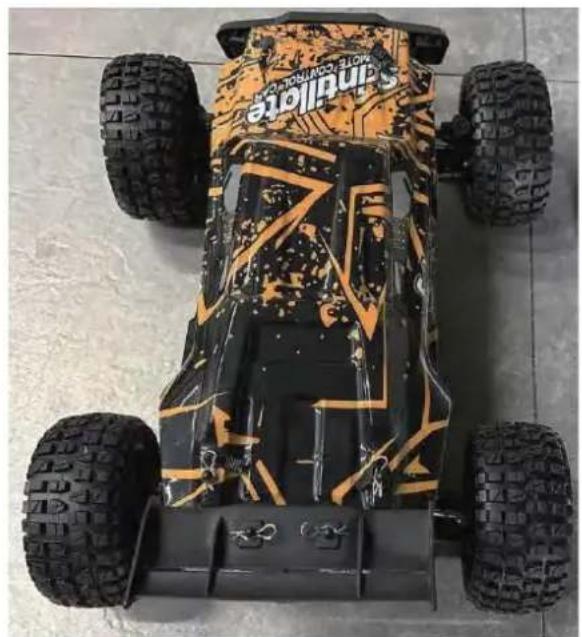
natural_image
Top-down view of a Sandville electric vehicle with four tires and camouflage pattern (no visible text or symbols)206E
BESOIN D'AIDE? CONTACTEZ-NOUS!
To make your experience with this remote control car as easy and convenient as possible, please read the instructions provided before using the product. Enjoy and have fun with the product while keeping the manual for future maintenance and reference.
- In order to protect the legitimate rights and interests of users, please be sure to carefully read the contents of this manual before using this product.
- When using this product, please be sure to strictly observe and perform the requirements which includes but not limited to the instructions and safety guidelines. For any personal injury, accident, property loss, legal dispute, or any other adverse event causing a conflict of interest resulting from the use of the product or any irresistible factors that are in violation of the safety instructions, the user shall bear the related responsibilities and losses.
- Once you start using the product, you are deemed to have read, understood, recommended, and accepted all terms and contents of the instructions (including disclaimers, safety instructions, warning instructions, etc.) included with this product.
- In case you are having challenges on any aspect of the product, may it be operation or maintenance, please contact your local sales agent
PACKAGE CONTENTS
 |  |  |  |  |  |
| RC Car | Remote Control | USB 7,4 V | LI-PO 7,4 V | Product Manual | Accessory package |
CHARGING
The battery isn't fully charged when it's made. When the car battery low, the car will start the LVC (Low Voltage Cutoff) protection function to protect the battery, the car can only turn, not forward and backward. Please charge the battery.
- Plug the USB charging cable into the USB charging port of the computer, power bank or USB adapter (5V@0.5\~2.0A).
- Connect the battery wire to the USB charging cable.
- Charging time: about 250 minutes.
- The green indicator light on the USB charging cable will flash when it is charging and will turn solide once fully charged.
ATTENTION:
- Please keep the battery in sight when charging. DO NOT put the battery on a flammable surface.
- If battery pack and USB charging cable are damaged, immediately stop using it and replace the accessories as soon as possible.
RC CAR'S DETAILS
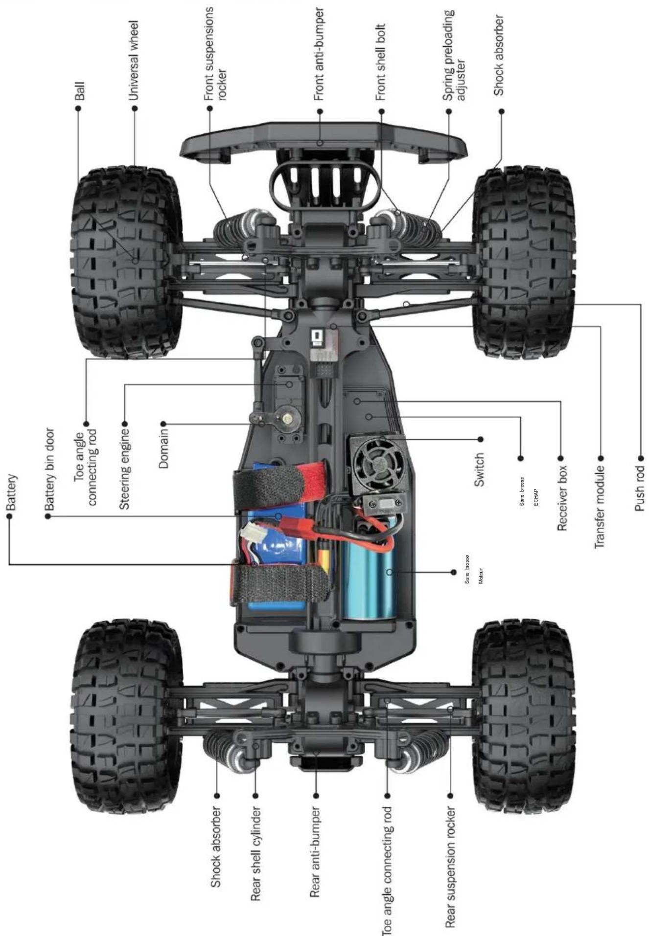
BATTERY INSTALLATION
REMOTE CONTROLLER
Our company has configured a new remote control for the model, Please ready the operation on the instruction manual carefully. Below is the functions description of this remote control.
■ Remote Control 1
Remote Control 2
Steering rate knob
Reverse direction of left and right
Throttle trim
Trun trim
Indicator light
ReVerse direction
Steering
2.Brake / 3.Backward
2.4GHz
- When the trigger is pulled back, the vehicle advances
- When the vehicle is moving forward, push the trigger forward and the vehicle will brake;
- When the trigger on the remote control returns to the midpoint, push the trigger forward again and the vehicle will retreat.
| LED color/pattern | Name | Hints |
| Red light always on | Normal driving pattern | |
| Red light with slow flash (on at 0.5s/off at 0.5s) | Hint of low power | For more information m please refer to operation of putting new battery into remote on page 6. |
| Red light with quick flash (on at 0.125s/off at 0.125s) | Connect failed/error | If transmitter and receiver are bound unsuccessfully, please close the remote system and restart for recovering normal operation. Please check exceeding scope, low battery or damaged antenna if the connection is failed. |
OPERATION
RC CAR BATTERY
① Take out the clip and open the battery cover.
② Connect the battery outlet to the cable in the battery compartment, then insert the battery to the batter compartment.
③ Close the battery cover and lock it.
If the car will not be used for a long time, make sure to turn it off and remove the battery.
natural_image
Close-up of a battery pack with red and blue wires, no visible text or symbolsREMOTE CONTROL BATTERY
natural_image
Top-down view of a black car component with a white arrow pointing to the side (no text or symbols visible)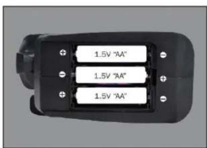
natural_image
Top-down view of a black car interior with three battery cells and an arrow pointing to one (no text or symbols)① Push the battery cover out.
② Insert 3 AA batteries (not included) in the correct direction.
③ Push the battery cover in.
If the remote will not be used for a long time, make sure to turn it off and remove the batteries.
When the battery of the remote control is low, the indicator light of the remote control will flash slowly.
OPERATION
PAIRING
natural_image
Close-up of a mechanical assembly with red and black components, no visible text or symbols① Make sure the battery is charged.
② Insert batteries to the car and the remote.
③ Turn on the car power switch and the remote power switch. (DO NOT pull the throttle trigger during pairing)
④ Both will automatically pair. (The remote power indicator and the car power indicator will flash while waiting for the pairing process and will turn solid once pairing has been successful)
FREQUENTLY ASKED QUESTIONS
FORWARD, REVERSE, TURN LEFT, TURN RIGHT
Pull the throttle trigger backward, the car goes forward. Push the throttle trigger forward, the car brakes, then push the throttle trigger forward again, the car goes reverse. (The throttle controls the speed)
Turn the steering control wheel counterclockwise, the car turns left. Turn the steering control wheel clockwise, the car turns right. ( Control the Steering Wheel Rotation Angle can control the degree of turning )
MAXIMUM SPEED CONTROL
Steering Rate Knob
Use the Steering Rate Knob to adjust direction angle when the steering wheel operated.
Increase the steering angle
FINE TUNING KNOB OF STEERING
Use throttle to adjust the speed into your ideal one by rotate left or rotate right
| QUESTION | CAUSE | SOLUTION |
| No match or can't control it | 1. The car battery or remote control battery is completely dead2. Out of remote range | 1. Replace charged battery2. Repair and keep in remote distance |
| Can't go forward or reverse | 1. Low battery2. The car shorted out when it got wet3. Poor contact between motor and electronic regulator | 1. Charging2. Let the car dry completely3. Reconnect the connection wire between the motor and the electronic regulator |
| Can't turn left or turn right | 1. The steering angle knob(ST.RATE) is set to minimum2. Low battery3. The car shorted out when it got wet3. Poor contact between steering gear and electronic regulator | 1. Set the steering angle knob (ST.RATE) to maximum2. Charging3. Let the car dry completely4. Reconnect the connection wire between the steering gear and the electronic regulator |
| It won't charge | 1. The output voltage or current of the power supply is too high2. The charging cable or battery is broken | 1. The output voltage and current of the power supply should be 5V 0.5~2A2. Contactez le service client |
| Something's missing or broken | Contactez le service client | |
| The wheels turn on their own | Pull the throttle trigger during pairing | Repair without pulling the throttle |
SPECIFICATIONS
Motor:
Battery:
Remote frequency:
Remote distance:
Charging mode:
Moteur sans balais
7,4 V lithium battery
2.4GHz
100m
USB balance charging cable
DEVICE EXPLOSION DIAGRAM
9200 ASSEMBLY VIEW
9203 ASSEMBLY VIEW
9204 CAR BOBY
DRIVE AXLE EXPLODED VIEW
9202 ASSEMBLY VIEW

9203 CAR BOBY
FRONT & REAR DIFFERENTIAL EXPLODED VIEW
natural_image
Exploded view diagram of a mechanical gear assembly (no text or symbols)TIRE & WHEEL AXLE EXPLODED VIEW
RETAIL ACCESSORY VIEW
PX9200-22
natural_image
Metal mechanical component with two circular holes, no visible text or markingsServo Link
PX9200-05
natural_image
3D rendering of a mechanical housing component with visible internal ribs and mounting holes (no text or symbols)Chassis
PX9200-06
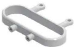
natural_image
3D rendering of a white plastic mechanical bracket with multiple cylindrical ports (no text or symbols)Tube-style bumpers
PX9200-07
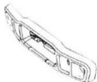
9200-Front/Rear Bumper
PX9200-09
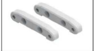
natural_image
Two white plastic mechanical components with circular holes, shown in isometric view (no text or symbols)Tie Bar
PX9200-10
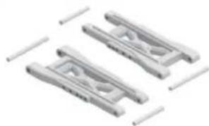
natural_image
Three identical mechanical clamping components with no visible text or symbolsLower Supension Arm
PX9200-11
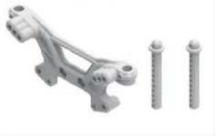
natural_image
3D rendered mechanical bracket with three screws, no text or symbols visibleFront Shock Tower and Body Post
PX9200-08

natural_image
Mechanical component with two screws and a bracket, shown alongside (no text or symbols visible)Rear Shock Tower and Body Post
PX9200-13
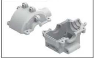
natural_image
Two white plastic mechanical housing components with mounting holes and internal cavities (no text or symbols visible)Front/Rear Gear Box
PX9200-14
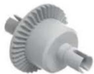
Diff Main Gear Complete
PX9200-15
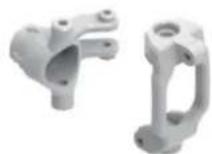
Front Steering Carrier
PX9200-16
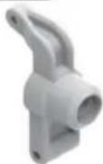
Rear Upright
PX9200-17
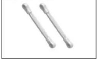
natural_image
Two metallic cylindrical objects with flanged ends, no text or symbols visibleFront/Rear Upper Link
PX9200-18
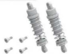
natural_image
Two metallic spring components with bolts and small pins, no text or symbols visibleFront/Rear Shock Absorber
PX9200-19
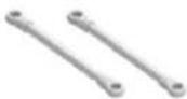
Steering Link
PX9200-20
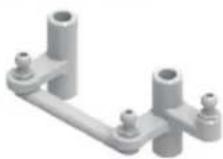
Steering Arm Complete
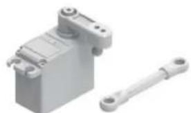
PX9200-51
natural_image
3D rendering of a gray mechanical component with a separate white rod (no text or symbols visible)Servo (3 fils)
RETAIL ACCESSORY VIEW
natural_image
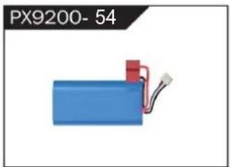
Blue battery with red connector and wire, labeled PX9200-54 (no other text or symbols)LIPO Battery (7.4V 4000MAH)
natural_image
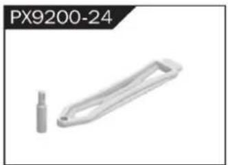
3D rendered mechanical part with a cylindrical end and a rectangular handle (no text or symbols visible)Battery Cover
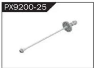
natural_image
Mechanical component labeled PX9200-25, showing a shaft with flanged ends and a central hub (no text or symbols on the part itself)Drive Shaft Assembly
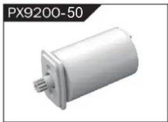
natural_image
Exterior view of a white cylindrical mechanical component (no text or symbols visible)Sans balais
Motor
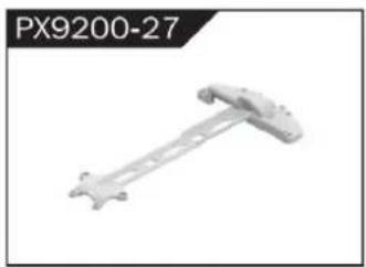
natural_image
Mechanical component labeled PX9200-27, showing a rod-like structure with mounting holes (no text or symbols on the object itself)Motor Layering
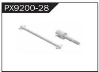
natural_image
Two mechanical components, one straight and one cylindrical, shown without any text or symbols.Universal Drive Joint
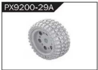
natural_image
3D rendered tire component labeled PX9200-29A, showing textured surface and mounting holes (no text or symbols on the object itself)Vacuum Wheel Complete
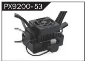
natural_image
Close-up of a black industrial device with cooling fan and cooling fins (no visible text or symbols)ESC
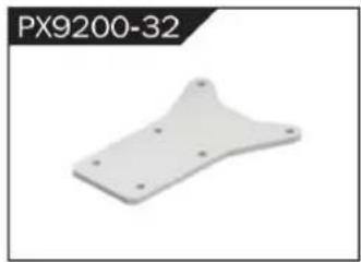
natural_image
White plastic mechanical part with mounting holes, labeled PX9200-32 (no other text or symbols)Chassis Sheet Steel
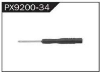
natural_image
Close-up of a black screwdriver with a metallic tip, labeled PX9200-34 (no other text or symbols visible)3MM Crosstip Screwdrivers
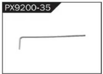
natural_image
Simple line drawing of a bent pipe or rod (no text or symbols)2MM Hexagon Wrench
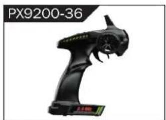
natural_image
Black handheld device labeled PX9200-36, showing a stylized creature with no visible text or symbols on the device itself.I 2.4G Transmitter for all

II 2.4G Transmitter for all
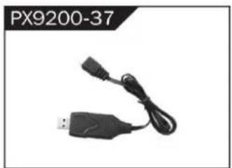
natural_image
Black USB and cable connector with connectors (no text or symbols visible)7.4 V- USB
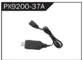
natural_image
Black USB device with attached cable and connector, labeled PX9200-37A (no other text or symbols visible)11,1 V- USB
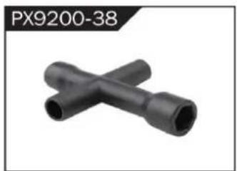
natural_image
Two black X-shaped pipe fittings (no text or symbols visible)Socket Wrench
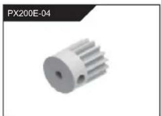
natural_image
3D rendered image of a white mechanical gear or rotor component (no text or symbols visible)natural_image
Metallic heat sink component with radial fins, no visible text or symbolsnatural_image
Group of metallic screw-like components arranged in two rows (no text or symbols visible)Φ2.6*7PB Round Head Screw
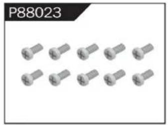
natural_image
Group of identical metallic screw-like components arranged in two rows (no text or symbols visible)Φ2.6*10PB Round Head Screw
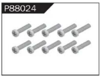
natural_image
Group of eight identical metallic bolts arranged in two rows (no text or symbols visible)Φ2.6*30PB Round Head Screw
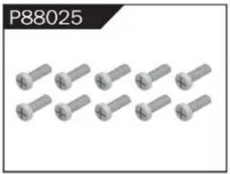
natural_image
Group of metallic screw-like components arranged in two rows (no text or symbols visible)Φ3*12 Round Head Screw

natural_image
Grid of nine identical screw-like components arranged in two rows (no text or symbols visible)Φ2.3*10PB Screw
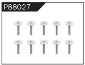
natural_image
Grid of nine identical screw-like components arranged in two rows (no text or symbols visible)Φ2.6*12PB Screw
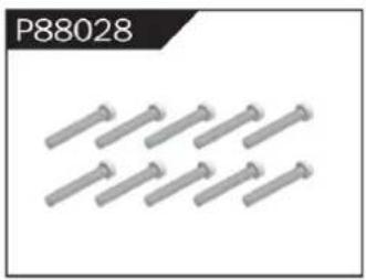
natural_image
Group of metallic bolts arranged in a row (no text or symbols visible)Φ1.7*8PB Screw
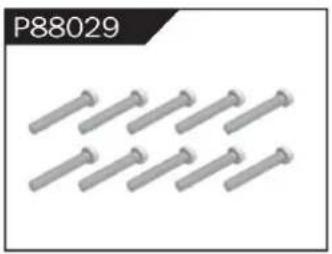
natural_image
Row of metallic screwdrivers arranged in two rows (no text or symbols visible)Φ2*8PB Screw
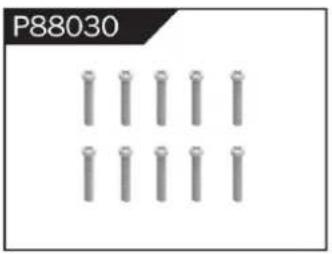
natural_image
Grid of metallic cylindrical pins arranged in three rows (no text or symbols)Φ2.3*14PB Screw

natural_image
Grid of metallic cylindrical pins arranged in three rows (no text or symbols visible)Φ2.6*14PB Screw
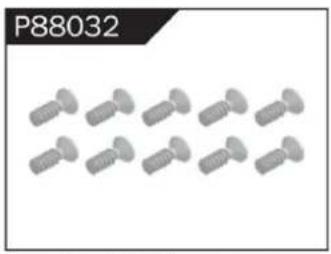
natural_image
Group of identical screwdrivers arranged in two rows (no text or symbols visible)Φ2.6*10 Flattened Head Screw
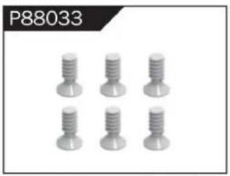
natural_image
Six identical screwdrivers arranged in two rows (no text or symbols visible)Φ3*8 Flattened Head Machine Screw
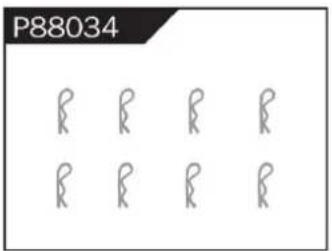
Body Clip
natural_image
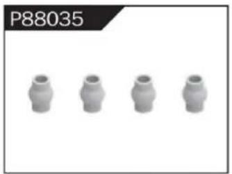
Four identical cylindrical mechanical components arranged horizontally (no text or symbols visible)Hollow Ball Connectors
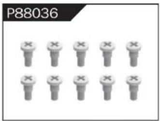
Step Screw
natural_image
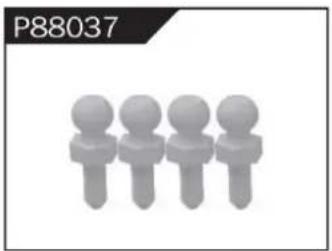
Four stylized human figures in a row, no text or symbols presentΦ4.8 Ball Head
natural_image
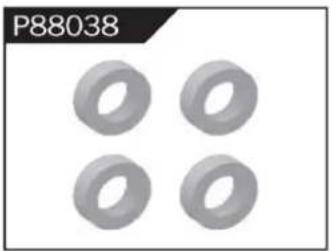
Four identical gray ring-shaped objects arranged in a 2x2 grid (no text or symbols)Φ10*15*4 Ball Bearing
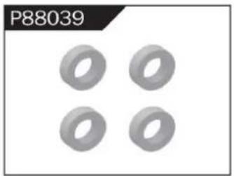
natural_image
Four identical gray ring shapes arranged in a 2x2 grid on a white background (no text or symbols)Φ8*10*3 Ball Bearing
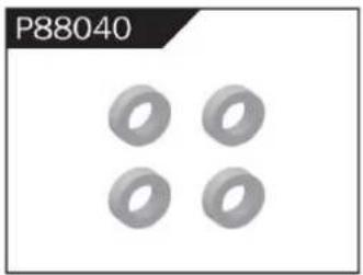
natural_image
Four identical gray ring shapes arranged in a 2x2 grid (no text or symbols)Φ5*9*3 Ball Bearing
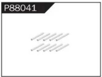
Φ1.5*10 Wheel Hex Pin c
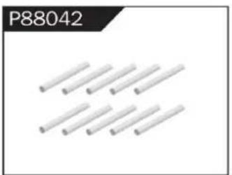
natural_image
Pure diagram of multiple parallel cylindrical rods without any text or symbolsΦ2.5*26.5 Steering Pin B
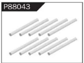
natural_image
Six white cylindrical rods arranged diagonally (no text or symbols visible)Φ3*48 Front/Rear Lower Suspension Pin A
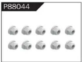
natural_image
Grid of 12 identical mechanical pipe fitting units (no text or symbols visible)Nylor Nut M4
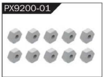
natural_image
12 gray hexagonal nuts arranged in two rows (no text or symbols visible)Wheel Hex
WARNINGS
- According to the instructions provided on the manual. Some part needs to be assembled and adjusted by adults.
- Please use under the guidance of an adult.
- Please promptly put away the packing materials so as not to cause harm to children.
- Do not operate on a location where water is trapped or under the rain. Parts of the product may malfunction if exposed to water.
- Do not touch the rotating wheel to avoid injury.
- The product contains small parts that may pose a risk of ingestion or suffocation.
- To remotely control the product on the road or in a crowd to avoid accidents.
- It is necessary to periodically check the charging USB cable, plug, housing and other components, and immediately unplug if found to be damaged.
- This product can only use the factory configured USB cable to charge the product battery.
- USB cable, battery box, and battery must be inserted into the same specified power supply as the product symbol.
- The USB charging cable and the battery is not a toy.
- Disconnect the rechargeable USB cable before cleaning the toy.
- If you observe electrical charges during product usage, turn off the device immediately.
- When installing or replacing the battery, pay attention to the correct polarity of the battery.
- The remote control car uses a 7.4V Lithium battery.
- It is strictly prohibited do the following actions such as but not limited to disassemble, modify, crash, puncture, drop, throw in a fire or any other means of causing damage to the product to avoid harm to the user and other participants.
- Do not expose the battery to prolonged exposure to sunlight to prevent danger.
- It is advisable to store the battery at a temperature below 30^ C. Do not store it in a place with heat, high temperature, or humidity to avoid danger.
- Non-rechargeable batteries cannot be charged.
- When charging a rechargeable battery, adult supervision is required.
- The rechargeable battery should be removed from the toy before charging.
- Do not mix old and new or different types of batteries.
- Only use the USB cable configured by this product when charging the battery.
- Do not disassemble the battery or modify the battery to avoid risk of fire or explosion.
- After the battery is used, it should be taken out of the remote control car. After cooling the battery, you can then charge it and placed it on a safe location. Unplug the battery outlet from the USB charging cable when not in used and disconnect the power line.
- Stop using the battery as soon as it gives a foul smells or suddenly becomes hot, deformed, discolored, or otherwise abnormal during use or charging.
- After the battery of the remote controller runs out, battery temperature is usually high and would recommend to wait for
30 minutes before charging the battery again. Otherwise, it may damage the battery. - Drained batteries should be removed immediately.
- Do not cause the electrical supply of the wiring port to short circuit.
- If you do not use the product for a long time, remove the batteries of the remote control car and remote control.
- instructions contains important product information, please give time to read for better product experience.
GENERAL INFORMATION
CAN NMB-3 (B)
RF Exposure
Radiation Exposure Statement:
This equipment complies with IC radiation exposure limits set forth for an uncontrolled environment. This equipment should be installed and operated with minimum distance 20cm between the radiator & your body.
BATTERY WARNING:
- Failure to follow all the instructions may result in serious injury, irreparable damage to the battery and may cause a fire, smoke or explosion.
- Always check the battery's condition before charging or using it.
- Replace the battery if damaged, gives a foul odor or show signs of overheating, discoloration, deformation and leakage.
- Never use anything other than the approval charger the battery. Always use a balancing charger for battery. It is recommended that you do not to use any other charger than the one provided with the product.
- The battery temperature must never exceed 60°C (140°F) otherwise the battery could be damaged or ignite.
- Never charge on a flammable surface, near flammable products or inside a vehicle (perferably place the battery in a non-flammable and nonconductive container).
- Never leave the battery unattended during the charging process. Never disassemble or modify the housing's wiring, or puncture the cells. Always ensure that the charger output voltage corresponds to the voltage of the battery. Do not overcharge the batter that may cause short circuit.
- Never expose the battery to moisture or direct sunlight, or store it in a place where temperatures could exceed 60^ C (car in the sun, for example).
- Always keep it out of reach from children.
- Improper battery use may result in a fire, explosion or other hazard.
- Non-rechargeable batteries are not be charge again. Rechargeable batteries are only to be charged with the supervision of an adult.
- Different types of batteries or new or used batteries which are different are not be mixed.
- Batteries are to be inserted with the correct polarity.
- The supply terminal should be used well to avoid short circuit. Examination of the transformer and battery charger regularly is encouraged to check any damage in the cord, plug, enclosure and other parts. If damage is observed, it must not be used until it has been repaired.
- The packaging has to be kept since it contains important information.
- The toy is only to be connected to Class II equipment bearing the symbol.
C/O YH Consulting Limited Bureau 147, Centurion House, London Road,
Staines-upon-Thames, Surrey, TW18 4AX
Importé en AUS : SIHAO PTY LTD.
1 ROKEVA STREET EASTWOOD NSW 2122 Australie
Suite 250, 9166 Anaheim Place, Rancho Cucamonga, CA 91730
VEVOR®
TOUGH TOOLS, HALF PRICE
www.vevor.com/support
natural_image
Top-down view of a black and white heavy-duty toy car with four large tires, no visible text or symbols on the vehicle itself.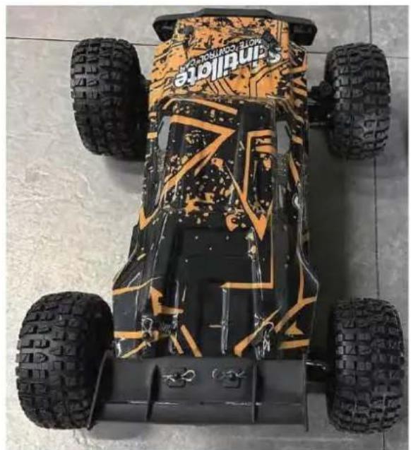
natural_image
Top-down view of a Sandville electric vehicle with four tires and camouflage pattern (no visible text or symbols)206E
To make your experience with this remote control car as easy and convenient as possible, please read the instructions provided before using the product. Enjoy and have fun with the product while keeping the manual for future maintenance and reference.
- In order to protect the legitimate rights and interests of users, please be sure to carefully read the contents of this manual before using this product.
- When using this product, please be sure to strictly observe and perform the requirements which includes but not limited to the instructions and safety guidelines. For any personal injury, accident, property loss, legal dispute, or any other adverse event causing a conflict of interest resulting from the use of the product or any irresistible factors that are in violation of the safety instructions, the user shall bear the related responsibilities and losses.
- Once you start using the product, you are deemed to have read, understood, recommended, and accepted all terms and contents of the instructions (including disclaimers, safety instructions, warning instructions, etc.) included with this product.
- In case you are having challenges on any aspect of the product, may it be operation or maintenance, please contact your local sales agent
PACKAGE CONTENTS
| | | | |  |
| RC Car | Remote Control | 7,4 V USB | 7,4 V LI-PO | Product Manual | Accessory package |
CHARGING
The battery isn't fully charged when it's made. When the car battery low, the car will start the LVC (Low Voltage Cutoff) protection function to protect the battery, the car can only turn, not forward and backward. Please charge the battery.
- Plug the USB charging cable into the USB charging port of the computer, power bank or USB adapter (5V@0.5\~2.0A).
- Connect the battery wire to the USB charging cable.
- Charging time: about 250 minutes.
- The green indicator light on the USB charging cable will flash when it is charging and will turn solide once fully charged.
ATTENTION:
- Please keep the battery in sight when charging. DO NOT put the battery on a flammable surface.
- If battery pack and USB charging cable are damaged, immediately stop using it and replace the accessories as soon as possible.
RC CAR'S DETAILS

BATTERY INSTALLATION
REMOTE CONTROLLER
Our company has configured a new remote control for the model, Please ready the operation on the instruction manual carefully. Below is the functions description of this remote control.
■ Remote Control 1
■ Remote Control 2

Steering rate knob
Reverse direction of left and right
Throttle trim
Trun trim
Indicator light
ReVerse direction
Steering
2.Brake / 3.Backward
2.4GHz
- When the trigger is pulled back, the vehicle advances
- When the vehicle is moving forward, push the trigger forward and the vehicle will brake;
- When the trigger on the remote control returns to the midpoint, push the trigger forward again and the vehicle will retreat.
| LED color/pattern | Name | Hints |
| Red light always on | Normal driving pattern | |
| Red light with slow flash (on at 0.5s/off at 0.5s) | Hint of low power | For more information m please refer to operation of putting new battery into remote on page 6. |
| Red light with quick flash (on at 0.125s/off at 0.125s) | Connect failed/error | If transmitter and receiver are bound unsuccessfully, please close the remote system and restart for recovering normal operation. Please check exceeding scope, low battery or damaged antenna if the connection is failed. |
OPERATION
RC CAR BATTERY
① Take out the clip and open the battery cover.
② Connect the battery outlet to the cable in the battery compartment, then insert the battery to the batter compartment.
③ Close the battery cover and lock it.
If the car will not be used for a long time, make sure to turn it off and remove the battery.
natural_image
Close-up of a battery pack with red and blue wires, no visible text or symbolsREMOTE CONTROL BATTERY
natural_image
Top-down view of a black car component with a white arrow pointing to the side (no text or symbols visible)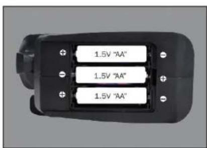
natural_image
Top-down view of a black car interior with three battery cells and an arrow pointing to one (no text or symbols)① Push the battery cover out.
② Insert 3 AA batteries (not included) in the correct direction.
③ Push the battery cover in.
If the remote will not be used for a long time, make sure to turn it off and remove the batteries.
When the battery of the remote control is low, the indicator light of the remote control will flash slowly.
OPERATION
PAIRING

natural_image
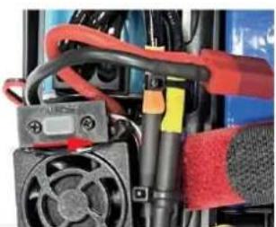
Close-up of a mechanical assembly with red and black components, no visible text or symbols① Make sure the battery is charged.
② Insert batteries to the car and the remote.
③ Turn on the car power switch and the remote power switch. (DO NOT pull the throttle trigger during pairing)
④ Both will automatically pair. (The remote power indicator and the car power indicator will flash while waiting for the pairing process and will turn solid once pairing has been successful)
FREQUENTLY ASKED QUESTIONS
FORWARD, REVERSE, TURN LEFT, TURN RIGHT
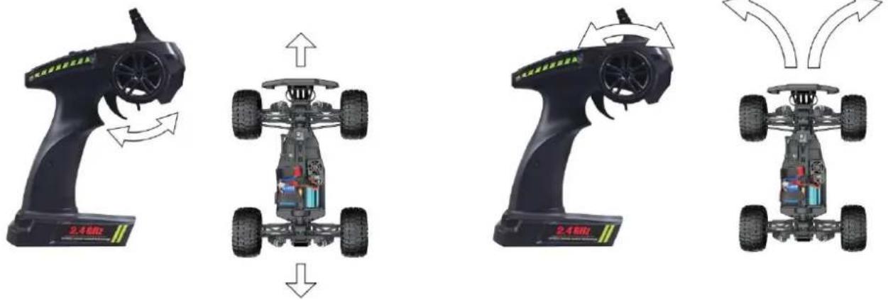
Pull the throttle trigger backward, the car goes forward. Push the throttle trigger forward, the car brakes, then push the throttle trigger forward again, the car goes reverse. (The throttle controls the speed)
Turn the steering control wheel counterclockwise, the car turns left. Turn the steering control wheel clockwise, the car turns right. ( Control the Steering Wheel Rotation Angle can control the degree of turning )
MAXIMUM SPEED CONTROL
Steering Rate Knob
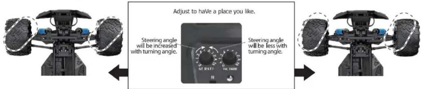
Use the Steering Rate Knob to adjust direction angle when the steering wheel operated.
Increase the steering angle
FINE TUNING KNOB OF STEERING
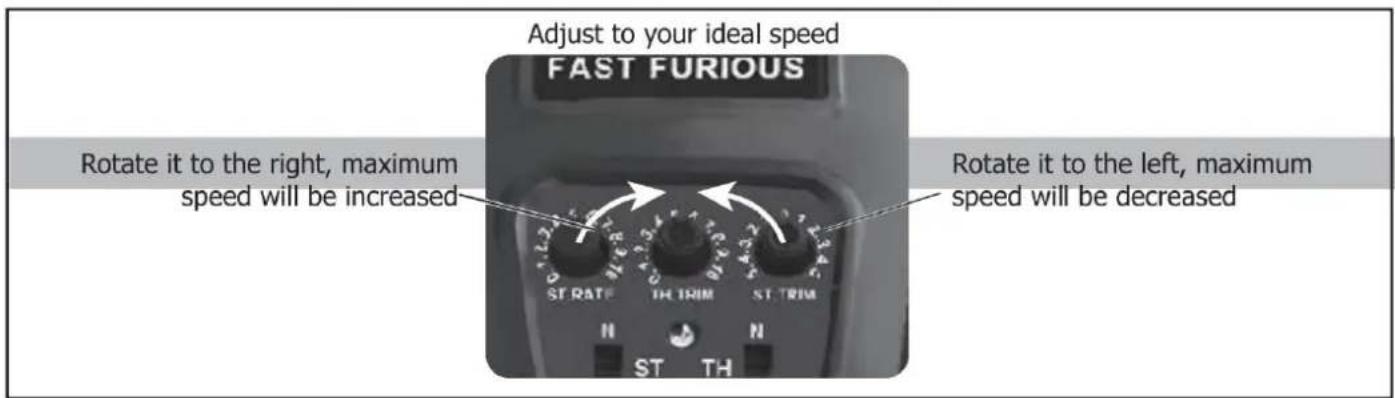
Use throttle to adjust the speed into your ideal one by rotate left or rotate right
| QUESTION | CAUSE | SOLUTION |
| No match or can't control it | 1. The car battery or remote control battery is completely dead2. Out of remote range | 1. Replace charged battery2. Repair and keep in remote distance |
| Can't go forward or reverse | 1. Low battery2. The car shorted out when it got wet3. Poor contact between motor and electronic regulator | 1. Charging2. Let the car dry completely3. Reconnect the connection wire between the motor and the electronic regulator |
| Can't turn left or turn right | 1. The steering angle knob(ST.RATE) is set to minimum2. Low battery3. The car shorted out when it got wet3. Poor contact between steering gear and electronic regulator | 1. Set the steering angle knob (ST.RATE) to maximum2. Charging3. Let the car dry completely4. Reconnect the connection wire between the steering gear and the electronic regulator |
| It won't charge | 1. The output voltage or current of the power supply is too high2. The charging cable or battery is broken | 1. The output voltage and current of the power supply should be 5V0.5~2A2. Kontaktieren Sie den Kundenservice |
| Something's missing or broken | Kontaktieren Sie den Kundenservice | |
| The wheels turn on their own | Pull the throttle trigger during pairing | Repair without pulling the throttle |
SPECIFICATIONS
Motor:
Battery:
Remote frequency:
Remote distance:
Charging mode:
Bürstenloser Motor
7,4 V lithium battery
2.4GHz
100m
USB balance charging cable
DEVICE EXPLOSION DIAGRAM
9200 ASSEMBLY VIEW
9203 ASSEMBLY VIEW
9204 CAR BOBY
DRIVE AXLE EXPLODED VIEW
9202 ASSEMBLY VIEW
9203 CAR BOBY
FRONT & REAR DIFFERENTIAL EXPLODED VIEW
natural_image
Exploded view diagram of a mechanical gear assembly (no text or symbols)TIRE & WHEEL AXLE EXPLODED VIEW
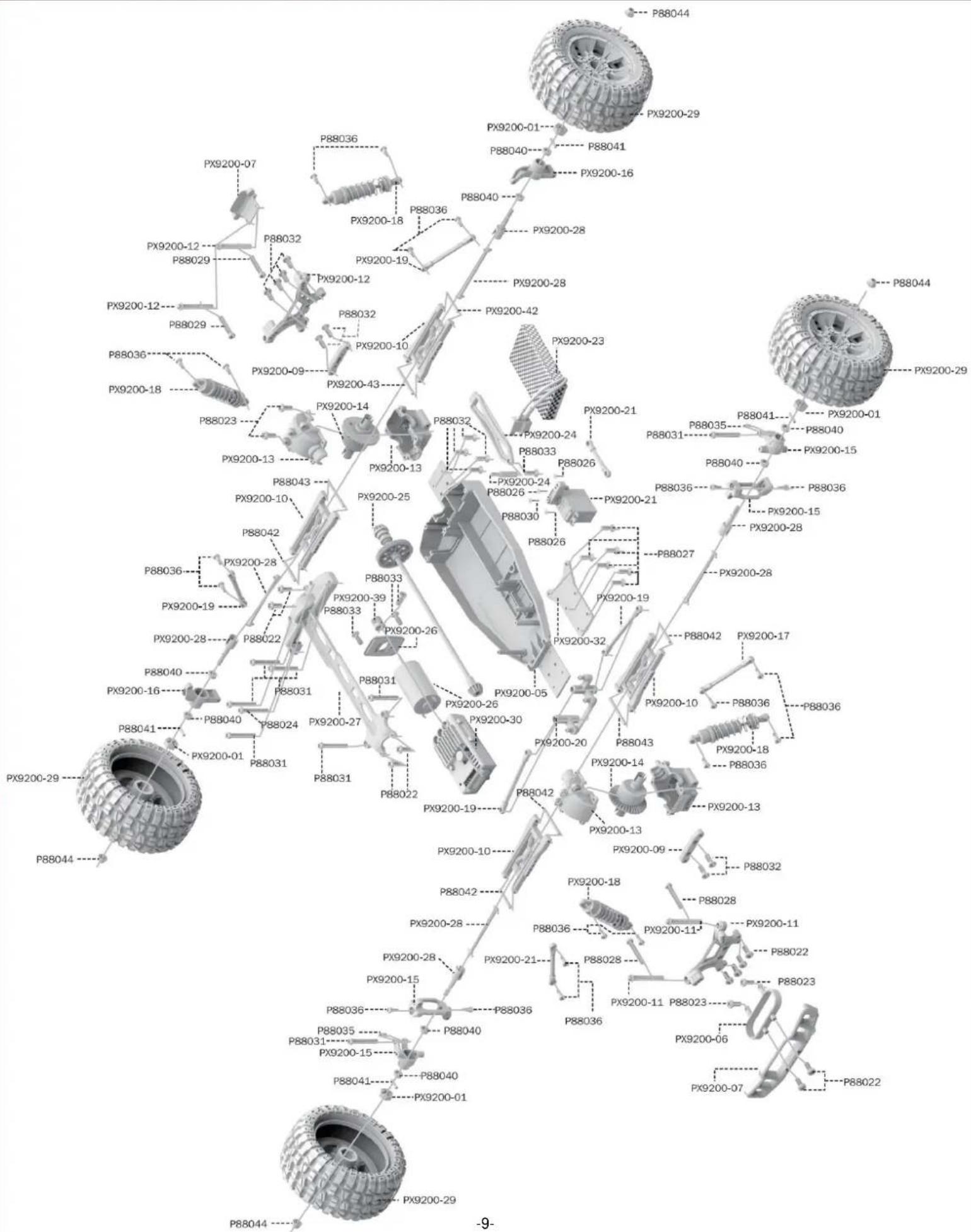
RETAIL ACCESSORY VIEW
PX9200-22
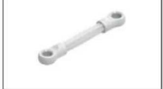
natural_image
Metal mechanical component with two circular ends (no text or symbols visible)Servo Link
PX9200-05
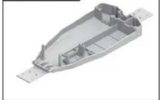
natural_image
3D rendering of a mechanical housing component with visible internal ribs and mounting holes (no text or symbols)Chassis
PX9200-06
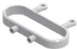
natural_image
3D rendering of a U-shaped mechanical component with two side ports (no text or symbols)Tube-style bumpers
PX9200-07

9200-Front/Rear Bumper
PX9200-09
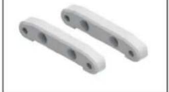
natural_image
Two white plastic mechanical components with circular holes, shown in isometric view (no text or symbols)Tie Bar
PX9200-10
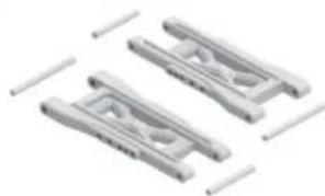
natural_image
Three identical mechanical clamping components with no visible text or symbolsLower Supension Arm
PX9200-11
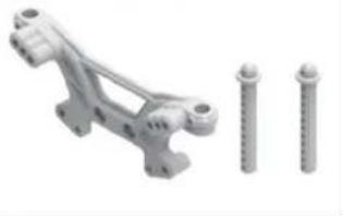
natural_image
3D rendered mechanical bracket with three screws, no text or symbols visibleFront Shock Tower and Body Post
PX9200-08
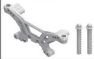
natural_image
Mechanical component with two screws and a bracket, shown alongside (no text or symbols visible)Rear Shock Tower and Body Post
PX9200-13
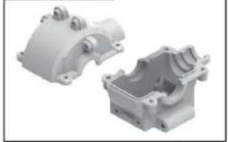
natural_image
Two white plastic mechanical housing components with mounting holes and internal cavities (no text or symbols visible)Front/Rear Gear Box
PX9200-14
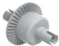
Diff Main Gear Complete
PX9200-15
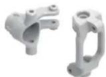
Front Steering Carrier
PX9200-16
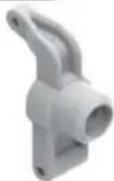
Rear Upright
PX9200-17
natural_image
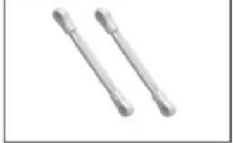
Two metallic cylindrical objects with flanged ends, no text or symbols visibleFront/Rear Upper Link
PX9200-18
natural_image
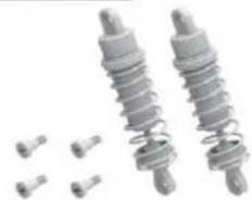
Two metallic spring components with bolts and small pins, no text or symbols visibleFront/Rear Shock Absorber
PX9200-19
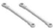
Steering Link
PX9200-20
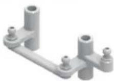
Steering Arm Complete
PX9200-51
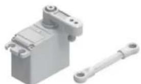
natural_image
3D rendering of a gray mechanical component with a separate white rod (no text or symbols visible)Servo (3-adrig)
RETAIL ACCESSORY VIEW
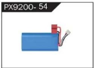
natural_image
Blue battery with red connector and wiring, labeled PX9200-54 (no other text or symbols)LIPO Battery (7.4V 4000MAH)
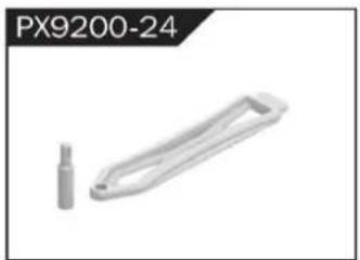
natural_image
Metallic mechanical component with a cylindrical pin and handle, labeled PX9200-24 (no other text or symbols)Battery Cover
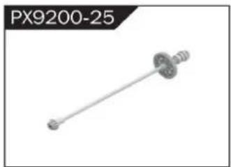
natural_image
Mechanical component labeled PX9200-25, showing a shaft with flanged ends and a central hub (no text or symbols on the part itself)Drive Shaft Assembly
natural_image
Exterior view of a white cylindrical mechanical component (no text or symbols visible)Bürstenlos Motor

natural_image
Mechanical component labeled PX9200-27, showing a rod-like structure with mounting holes (no text or symbols on the part itself)Motor Layering
natural_image
Two mechanical components, one straight and one cylindrical, shown without any text or symbols.Universal Drive Joint
natural_image
3D rendered tire component labeled PX9200-29A, showing textured surface and mounting holes (no text or symbols on the object itself)Vacuum Wheel Complete
natural_image
Close-up of a black industrial device with cooling fan and cooling fins (no visible text or symbols)ESC
natural_image
White plastic mechanical part with mounting holes, labeled PX9200-32 (no other text or symbols)Chassis Sheet Steel
natural_image
Close-up of a black screwdriver with a metallic tip, labeled PX9200-34 (no other text or symbols visible)3MM Crosstip Screwdrivers
natural_image
Simple line drawing of a bent pipe or rod (no text or symbols)2MM Hexagon Wrench
natural_image
Black handheld device labeled PX9200-36, showing a stylized creature with no visible text or symbols on the device itself.I 2.4G Transmitter for all

II 2.4G Transmitter for all
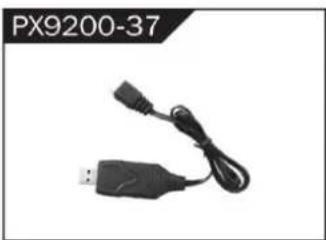
natural_image
Black USB and cable connector with a connector, labeled PX9200-37 (no other text or symbols visible)7,4V- USB
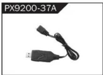
natural_image
Black USB plug with attached cable, labeled PX9200-37A (no other text or symbols visible)11,1 V- USB
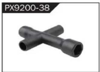
natural_image
Two black X-shaped pipe fittings (no text or symbols visible)Socket Wrench
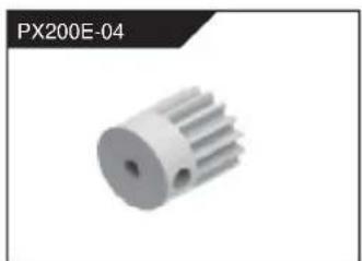
natural_image
3D rendered image of a white mechanical gear or rotor component (no text or symbols visible)Motorgetriebe (17t)
natural_image
Metallic heat sink component with radial fins, no visible text or symbolsnatural_image
Group of metallic screw-like components arranged in two rows (no text or symbols visible)Φ2.6*7PB Round Head Screw
natural_image
Group of identical metallic screw-like components arranged in two rows (no text or symbols visible)Φ2.6*10PB Round Head Screw
natural_image
Group of eight identical metallic bolts arranged in two rows (no text or symbols visible)Φ2.6*30PB Round Head Screw
natural_image
Group of metallic screw-like components arranged in two rows (no text or symbols visible)Φ3*12 Round Head Screw
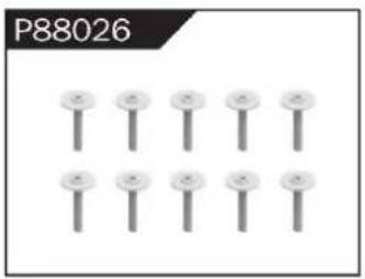
natural_image
Grid of nine identical screw-like components arranged in two rows (no text or symbols visible)Φ2.3*10PB Screw
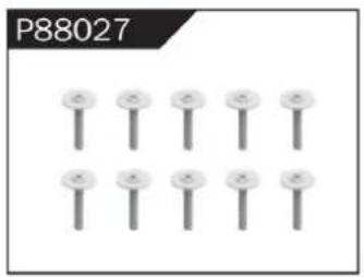
natural_image
Grid of nine identical screw-like components arranged in two rows (no text or symbols visible)Φ2.6*12PB Screw
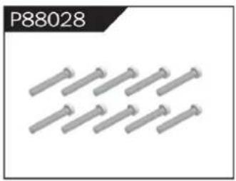
natural_image
Group of metallic bolts arranged in a row (no text or symbols visible)Φ1.7*8PB Screw
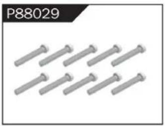
natural_image
Row of metallic bolts arranged in two rows (no text or symbols visible)Φ2*8PB Screw
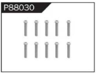
natural_image
Grid of metallic cylindrical pins arranged in three rows (no text or symbols)Φ2.3*14PB Screw
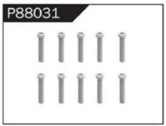
natural_image
Grid of metallic cylindrical pins arranged in three rows (no text or symbols visible)Φ2.6*14PB Screw
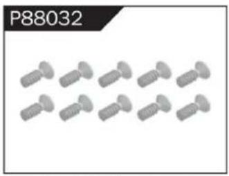
natural_image
Group of identical screwdrivers arranged in two rows (no text or symbols visible)Φ2.6*10 Flattened Head Screw

natural_image
Six identical screw-like components arranged in two rows (no text or symbols visible)Φ3*8 Flattened Head Machine Screw
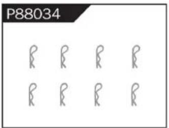
Body Clip
natural_image
Four identical cylindrical mechanical parts arranged horizontally (no text or symbols visible)Hollow Ball Connectors
Step Screw

natural_image
Four stylized human figures in a row, no text or symbols presentΦ4.8 Ball Head
natural_image
Four identical gray ring-shaped objects arranged in a 2x2 grid (no text or symbols)Φ10*15*4 Ball Bearing
natural_image
Four gray ring-shaped objects arranged in a 2x2 grid (no text or symbols)Φ8*10*3 Ball Bearing
natural_image
Four identical gray ring shapes arranged in a 2x2 grid (no text or symbols)Φ5*9*3 Ball Bearing
Φ1.5*10 Wheel Hex Pin c
natural_image
Pure diagram of multiple parallel cylindrical rods without any text or symbolsΦ2.5*26.5 Steering Pin B
natural_image
Close-up of white cylindrical rods arranged in a diagonal pattern (no text or symbols visible)Φ3*48 Front/Rear Lower Suspension Pin A
natural_image
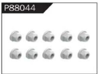
Grid of 12 identical mechanical pipe fitting units, no text or symbols visibleNylor Nut M4
natural_image
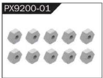
12 gray hexagonal nuts arranged in two rows (no text or symbols visible)Wheel Hex
WARNINGS
- According to the instructions provided on the manual. Some part needs to be assembled and adjusted by adults.
- Please use under the guidance of an adult.
- Please promptly put away the packing materials so as not to cause harm to children.
- Do not operate on a location where water is trapped or under the rain. Parts of the product may malfunction if exposed to water.
- Do not touch the rotating wheel to avoid injury.
- The product contains small parts that may pose a risk of ingestion or suffocation.
- To remotely control the product on the road or in a crowd to avoid accidents.
- It is necessary to periodically check the charging USB cable, plug, housing and other components, and immediately unplug if found to be damaged.
- This product can only use the factory configured USB cable to charge the product battery.
- USB cable, battery box, and battery must be inserted into the same specified power supply as the product symbol.
- The USB charging cable and the battery is not a toy.
- Disconnect the rechargeable USB cable before cleaning the toy.
- If you observe electrical charges during product usage, turn off the device immediately.
- When installing or replacing the battery, pay attention to the correct polarity of the battery.
- The remote control car uses a 7.4V Lithium battery.
- It is strictly prohibited do the following actions such as but not limited to disassemble, modify, crash, puncture, drop, throw in a fire or any other means of causing damage to the product to avoid harm to the user and other participants.
- Do not expose the battery to prolonged exposure to sunlight to prevent danger.
- It is advisable to store the battery at a temperature below 30^ C. Do not store it in a place with heat, high temperature, or humidity to avoid danger.
- Non-rechargeable batteries cannot be charged.
- When charging a rechargeable battery, adult supervision is required.
- The rechargeable battery should be removed from the toy before charging.
- Do not mix old and new or different types of batteries.
- Only use the USB cable configured by this product when charging the battery.
- Do not disassemble the battery or modify the battery to avoid risk of fire or explosion.
- After the battery is used, it should be taken out of the remote control car. After cooling the battery, you can then charge it and placed it on a safe location. Unplug the battery outlet from the USB charging cable when not in used and disconnect the power line.
- Stop using the battery as soon as it gives a foul smells or suddenly becomes hot, deformed, discolored, or otherwise abnormal during use or charging.
- After the battery of the remote controller runs out, battery temperature is usually high and would recommend to wait for
30 minutes before charging the battery again. Otherwise, it may damage the battery. - Drained batteries should be removed immediately.
- Do not cause the electrical supply of the wiring port to short circuit.
- If you do not use the product for a long time, remove the batteries of the remote control car and remote control.
- instructions contains important product information, please give time to read for better product experience.
GENERAL INFORMATION
CAN NMB-3 (B)
RF Exposure
Radiation Exposure Statement:
This equipment complies with IC radiation exposure limits set forth for an uncontrolled environment. This equipment should be installed and operated with minimum distance 20cm between the radiator & your body.
BATTERY WARNING:
- Failure to follow all the instructions may result in serious injury, irreparable damage to the battery and may cause a fire, smoke or explosion.
- Always check the battery's condition before charging or using it.
- Replace the battery if damaged, gives a foul odor or show signs of overheating, discoloration, deformation and leakage.
- Never use anything other than the approval charger the battery. Always use a balancing charger for battery. It is recommended that you do not to use any other charger than the one provided with the product.
- The battery temperature must never exceed 60°C (140°F) otherwise the battery could be damaged or ignite.
- Never charge on a flammable surface, near flammable products or inside a vehicle (perferably place the battery in a non-flammable and nonconductive container).
- Never leave the battery unattended during the charging process. Never disassemble or modify the housing's wiring, or puncture the cells. Always ensure that the charger output voltage corresponds to the voltage of the battery. Do not overcharge the batter that may cause short circuit.
- Never expose the battery to moisture or direct sunlight, or store it in a place where temperatures could exceed 60^ C (car in the sun, for example).
- Always keep it out of reach from children.
- Improper battery use may result in a fire, explosion or other hazard.
- Non-rechargeable batteries are not be charge again. Rechargeable batteries are only to be charged with the supervision of an adult.
- Different types of batteries or new or used batteries which are different are not be mixed.
- Batteries are to be inserted with the correct polarity.
- The supply terminal should be used well to avoid short circuit. Examination of the transformer and battery charger regularly is encouraged to check any damage in the cord, plug, enclosure and other parts. If damage is observed, it must not be used until it has been repaired.
- The packaging has to be kept since it contains important information.
- The toy is only to be connected to Class II equipment bearing the symbol.
C/O YH Consulting Limited Office 147, Centurion House, London Road,
Staines-upon-Thames, Surrey, TW18 4AX
Suite 250, 9166 Anaheim Place, Rancho Cucamonga, CA 91730
VEVOR®
TOUGH TOOLS, HALF PRICE
www.vevor.com/support
VEVOR®
TOUGH TOOLS, HALF PRICE
elettronica www.vevor.com/support
natural_image
Top-down view of a black and white heavy-duty toy car with four large tires, no visible text or symbols on the vehicle itself.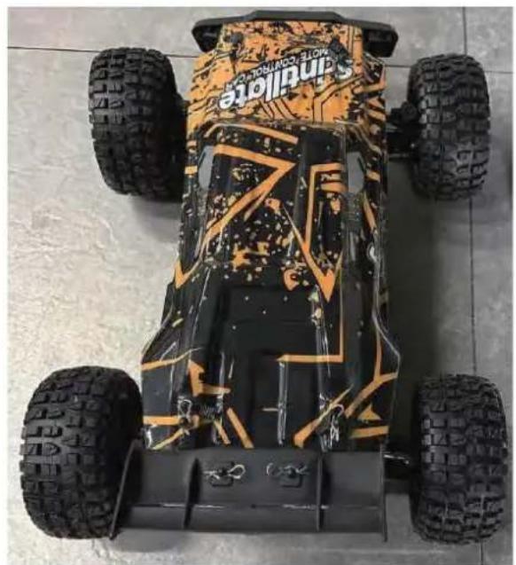
natural_image
Top-down view of a Sandville electric vehicle with four tires and camouflage pattern (no visible text or symbols)206E
To make your experience with this remote control car as easy and convenient as possible, please read the instructions provided before using the product. Enjoy and have fun with the product while keeping the manual for future maintenance and reference.
- In order to protect the legitimate rights and interests of users, please be sure to carefully read the contents of this manual before using this product.
- When using this product, please be sure to strictly observe and perform the requirements which includes but not limited to the instructions and safety guidelines. For any personal injury, accident, property loss, legal dispute, or any other adverse event causing a conflict of interest resulting from the use of the product or any irresistible factors that are in violation of the safety instructions, the user shall bear the related responsibilities and losses.
- Once you start using the product, you are deemed to have read, understood, recommended, and accepted all terms and contents of the instructions (including disclaimers, safety instructions, warning instructions, etc.) included with this product.
- In case you are having challenges on any aspect of the product, may it be operation or maintenance, please contact your local sales agent
PACKAGE CONTENTS
 | 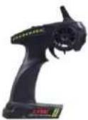 | 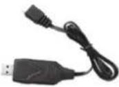 | 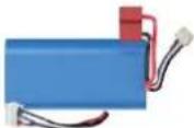 |  |  |
| RC Car | Remote Control | 7,4 V USB | LI-PO da 7,4 V | Product Manual | Accessory package |
CHARGING
The battery isn't fully charged when it's made. When the car battery low, the car will start the LVC (Low Voltage Cutoff) protection function to protect the battery, the car can only turn, not forward and backward. Please charge the battery.
- Plug the USB charging cable into the USB charging port of the computer, power bank or USB adapter (5V@0.5\~2.0A).
- Connect the battery wire to the USB charging cable.
- Charging time: about 250 minutes.
- The green indicator light on the USB charging cable will flash when it is charging and will turn solido once fully charged.
ATTENTION:
- Please keep the battery in sight when charging. DO NOT put the battery on a flammable surface.
- If battery pack and USB charging cable are damaged, immediately stop using it and replace the accessories as soon as possible.
RC CAR'S DETAILS
BATTERY INSTALLATION
REMOTE CONTROLLER
Our company has configured a new remote control for the model, Please ready the operation on the instruction manual carefully. Below is the functions description of this remote control.
■ Remote Control 1
Remote Control 2
Steering rate knob
Reverse direction of left and right
Throttle trim
Trun trim
Indicator light
ReVerse direction
Steering
2.Brake / 3.Backward
2.4GHz
- When the trigger is pulled back, the vehicle advances
- When the vehicle is moving forward, push the trigger forward and the vehicle will brake;
- When the trigger on the remote control returns to the midpoint, push the trigger forward again and the vehicle will retreat.
| LED color/pattern | Name | Hints |
| Red light always on | Normal driving pattern | |
| Red light with slow flash (on at 0.5s/off at 0.5s) | Hint of low power | For more information m please refer to operation of putting new battery into remote on page 6. |
| Red light with quick flash (on at 0.125s/off at 0.125s) | Connect failed/error | If transmitter and receiver are bound unsuccessfully, please close the remote system and restart for recovering normal operation. Please check exceeding scope, low battery or damaged antenna if the connection is failed. |
OPERATION
RC CAR BATTERY
① Take out the clip and open the battery cover.
② Connect the battery outlet to the cable in the battery compartment, then insert the battery to the batter compartment.
③ Close the battery cover and lock it.
If the car will not be used for a long time, make sure to turn it off and remove the battery.
natural_image
Close-up of a battery pack with red and blue wires, no visible text or symbolsREMOTE CONTROL BATTERY
natural_image
Top-down view of a black car component with a white arrow pointing to the side (no text or symbols visible)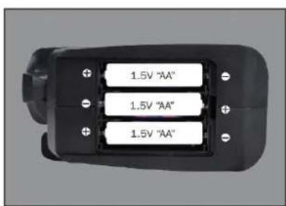
natural_image
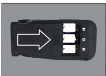
Top-down view of a black car interior with three battery cells and an arrow pointing to one (no text or symbols)① Push the battery cover out.
② Insert 3 AA batteries (not included) in the correct direction.
③ Push the battery cover in.
If the remote will not be used for a long time, make sure to turn it off and remove the batteries.
When the battery of the remote control is low, the indicator light of the remote control will flash slowly.
OPERATION
PAIRING
natural_image
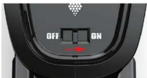
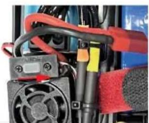
Close-up of a mechanical device with red and black components, no visible text or symbols① Make sure the battery is charged.
② Insert batteries to the car and the remote.
③ Turn on the car power switch and the remote power switch. (DO NOT pull the throttle trigger during pairing)
④ Both will automatically pair. (The remote power indicator and the car power indicator will flash while waiting for the pairing process and will turn solid once pairing has been successful)
FREQUENTLY ASKED QUESTIONS
FORWARD, REVERSE, TURN LEFT, TURN RIGHT
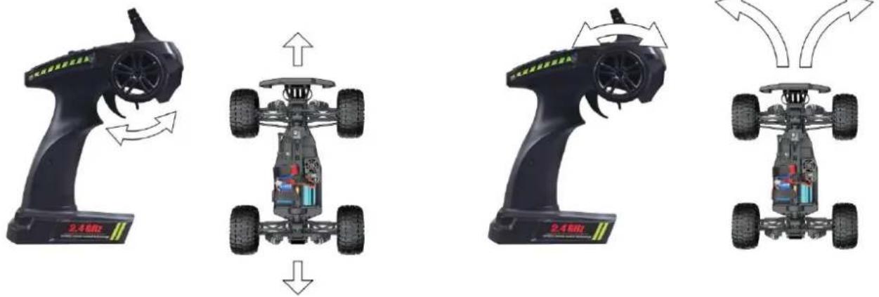
Pull the throttle trigger backward, the car goes forward. Push the throttle trigger forward, the car brakes, then push the throttle trigger forward again, the car goes reverse. (The throttle controls the speed)
Turn the steering control wheel counterclockwise, the car turns left. Turn the steering control wheel clockwise, the car turns right. ( Control the Steering Wheel Rotation Angle can control the degree of turning )
MAXIMUM SPEED CONTROL
Steering Rate Knob
Use the Steering Rate Knob to adjust direction angle when the steering wheel operated.
Increase the steering angle
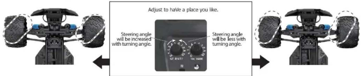
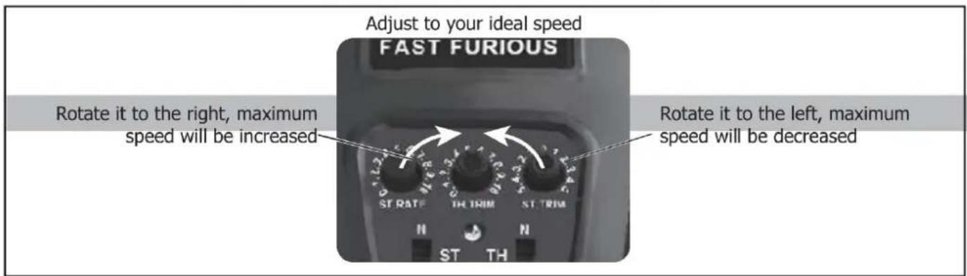
FINE TUNING KNOB OF STEERING
Use throttle to adjust the speed into your ideal one by rotate left or rotate right
| QUESTION | CAUSE | SOLUTION |
| No match or can't control it | 1. The car battery or remote control battery is completely dead2. Out of remote range | 1. Replace charged battery2. Repair and keep in remote distance |
| Can't go forward or reverse | 1. Low battery2. The car shorted out when it got wet3. Poor contact between motor and electronic regulator | 1. Charging2. Let the car dry completely3. Reconnect the connection wire between the motor and the electronic regulator |
| Can't turn left or turn right | 1. The steering angle knob(ST.RATE) is set to minimum2. Low battery3. The car shorted out when it got wet3. Poor contact between steering gear and electronic regulator | 1. Set the steering angle knob (ST.RATE) to maximum2. Charging3. Let the car dry completely4. Reconnect the connection wire between the steering gear and the electronic regulator |
| It won't charge | 1. The output voltage or current of the power supply is too high2. The charging cable or battery is broken | 1. The output voltage and current of the power supply should be 5V 0.5~2A2. Contatta il servizio clienti |
| Something's missing or broken | Contatta il servizio clienti | |
| The wheels turn on their own | Pull the throttle trigger during pairing | Repair without pulling the throttle |
SPECIFICATIONS
Motor:
Battery:
Remote frequency:
Remote distance:
Charging mode:
Motore Brushless
7,4 V lithium battery
2.4GHz
100m
USB balance charging cable
DEVICE EXPLOSION DIAGRAM
9200 ASSEMBLY VIEW
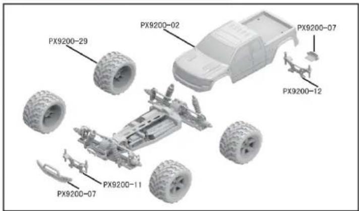
9203 ASSEMBLY VIEW
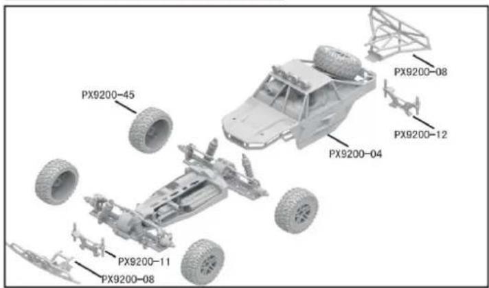
9204 CAR BOBY
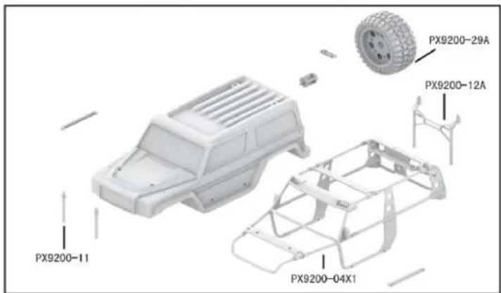
DRIVE AXLE EXPLODED VIEW
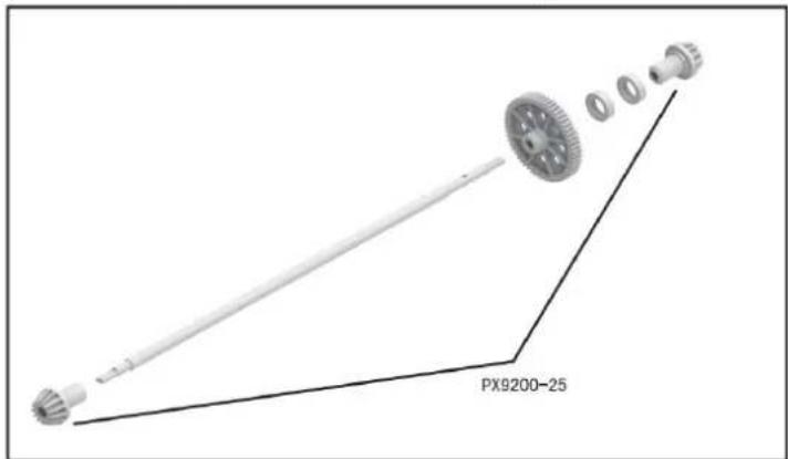
9202 ASSEMBLY VIEW
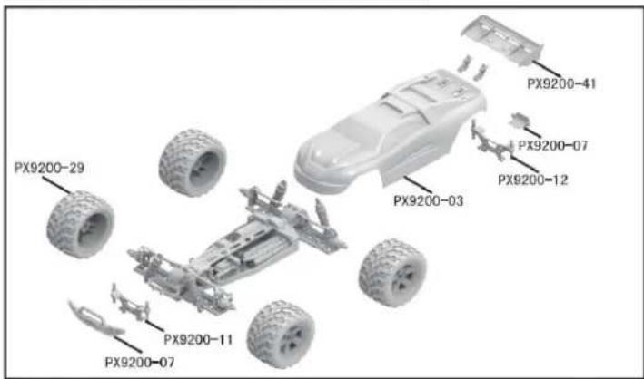
9203 CAR BOBY

FRONT & REAR DIFFERENTIAL EXPLODED VIEW
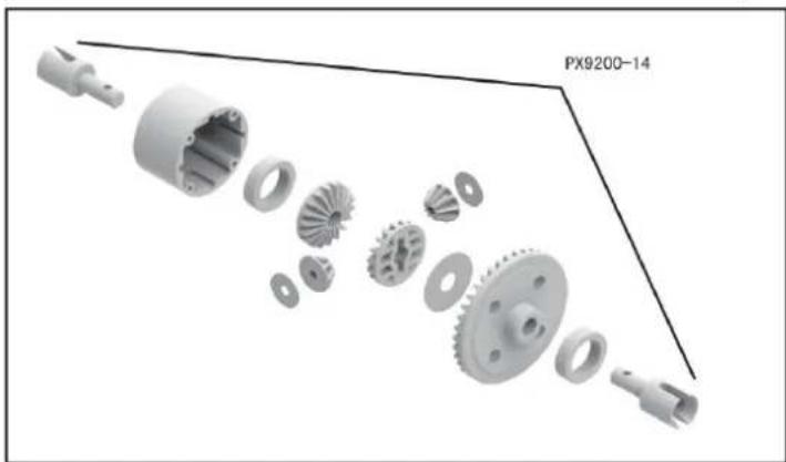
natural_image
Exploded view diagram of a mechanical gear assembly (no text or symbols)TIRE & WHEEL AXLE EXPLODED VIEW
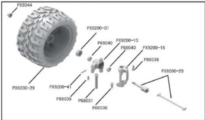
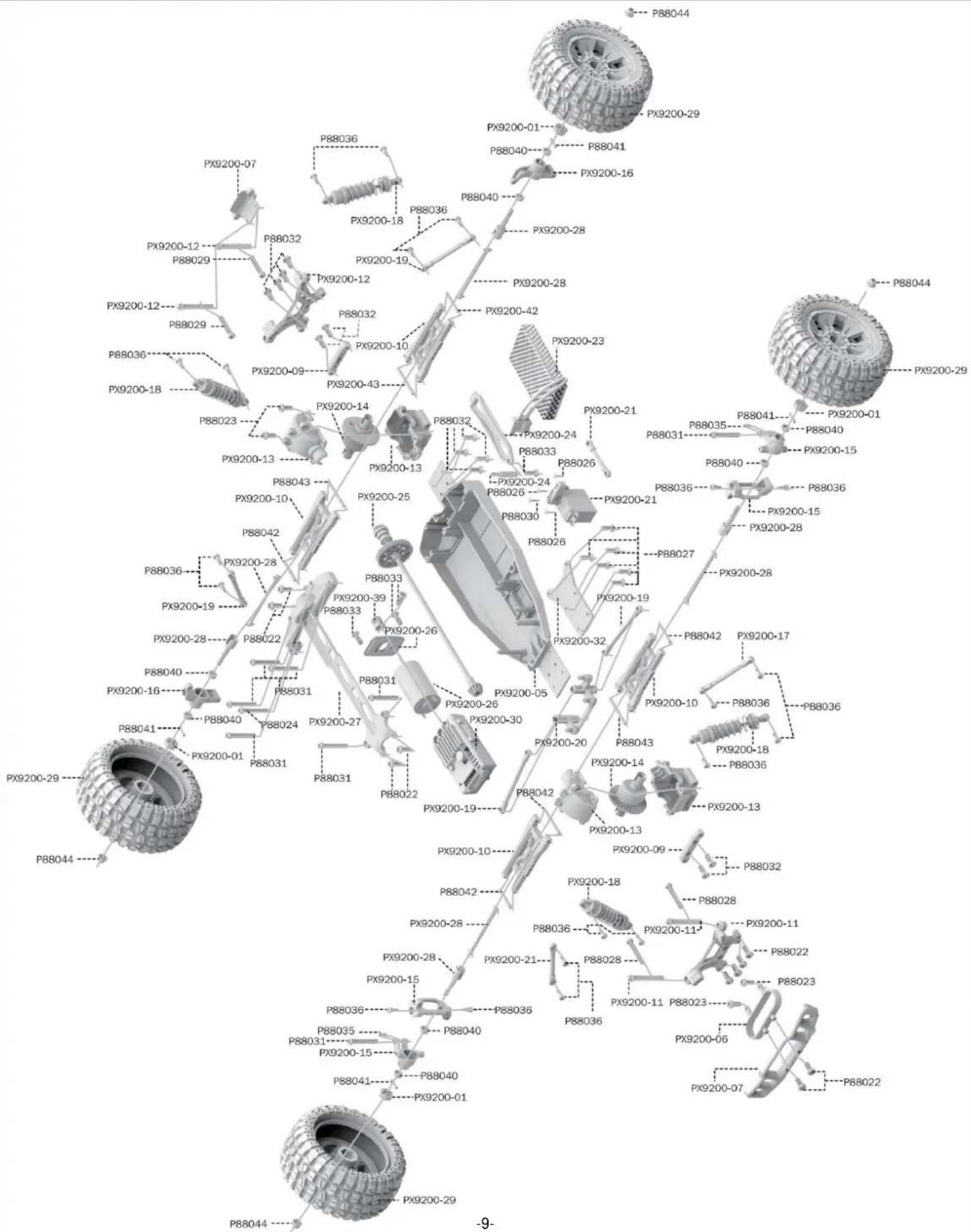
RETAIL ACCESSORY VIEW
PX9200-22
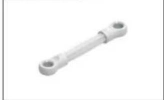
natural_image
Simple 3D rendering of a mechanical link or rod with two circular ends (no text or symbols)Servo Link
PX9200-05
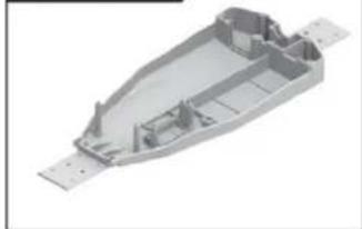
natural_image
3D rendering of a mechanical housing component with internal compartments and mounting holes (no text or symbols)Chassis
PX9200-06
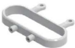
Tube-style bumpers
PX9200-07
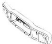
9200-Front/Rear Bumper
PX9200-09
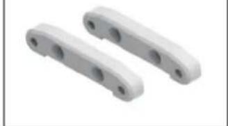
natural_image
Two white plastic mechanical components with circular holes, shown against a plain background (no text or symbols)Tie Bar
PX9200-10
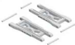
natural_image
Three identical mechanical component designs with no visible text or symbolsLower Supension Arm
PX9200-11
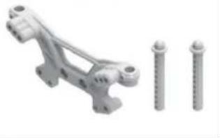
natural_image
3D rendered mechanical bracket with three screws, no text or symbols visibleFront Shock Tower and Body Post
PX9200-08
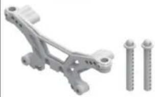
natural_image
Mechanical assembly with two screws and a bracket (no text or symbols visible)Rear Shock Tower and Body Post
PX9200-13
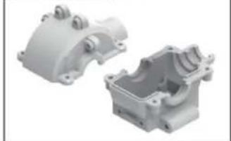
natural_image
Two views of a white plastic mechanical housing component, one open and one closed, with no visible text or symbols.Front/Rear Gear Box
PX9200-14
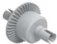
Diff Main Gear Complete
PX9200-15
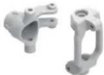
Front Steering Carrier
PX9200-16
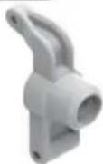
Rear Upright
PX9200-17
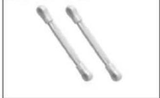
natural_image
Two metallic cylindrical objects with flanged ends, no text or symbols visibleFront/Rear Upper Link
PX9200-18
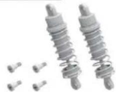
natural_image
Two metallic spring components with bolts and small pins, no text or symbols visibleFront/Rear Shock Absorber
PX9200-19
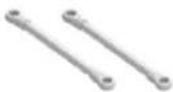
Steering Link
PX9200-20
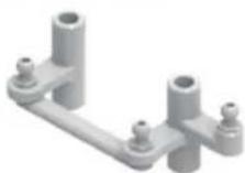
Steering Arm Complete
Modello PX9200-51
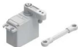
natural_image
3D rendering of a mechanical device with a shaft and housing (no text or symbols visible)Servo (3 fili)
RETAIL ACCESSORY VIEW
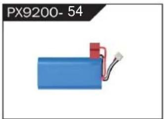
natural_image
Blue battery with red connector and wire, labeled PX9200-54 (no other text or symbols)LIPO Battery (7.4V 4000MAH)
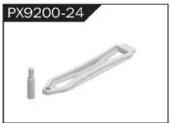
natural_image
Metallic mechanical component labeled PX9200-24, no other text or symbols visibleBattery Cover
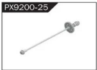
natural_image
Mechanical component labeled PX9200-25, showing a shaft with flanged ends and a central hub (no text or symbols on the part itself)Drive Shaft Assembly

natural_image
Exterior view of a white cylindrical mechanical component (no text or symbols visible)natural_image
Mechanical component labeled PX9200-27, showing a rod-like structure with mounting holes (no text or symbols on the object itself)Motor Layering
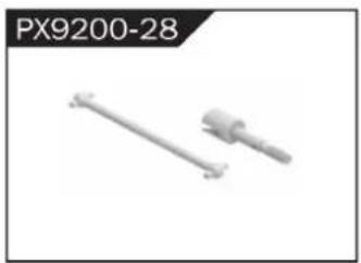
natural_image
Two mechanical components, one straight and one cylindrical, shown without any text or symbols.Universal Drive Joint
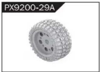
natural_image
3D rendered tire component labeled PX9200-29A, showing textured surface and mounting holes (no text or symbols on the object itself)Vacuum Wheel Complete
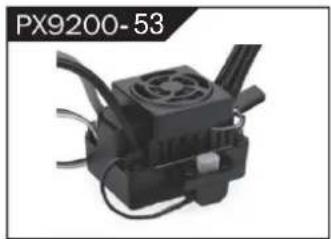
natural_image
Close-up of a black industrial device with cooling fan and cooling fins (no visible text or symbols)ESC
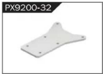
natural_image
White plastic mechanical part with mounting holes, labeled PX9200-32 (no other text or symbols)Chassis Sheet Steel
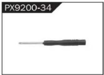
natural_image
Close-up of a black screwdriver with a metallic tip, labeled PX9200-34 (no other text or symbols visible)3MM Crosstip Screwdrivers
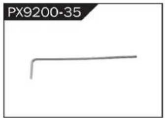
natural_image
Simple line drawing of a bent pipe or rod (no text or symbols)2MM Hexagon Wrench
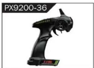
natural_image
Black handheld device labeled PX9200-36, showing a stylized creature with no visible text or symbols on the device itself.I 2.4G Transmitter for all

II 2.4G Transmitter for all
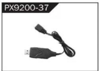
natural_image
Black USB and cable connector (no text or symbols visible)7,4 V- USB
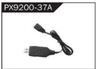
natural_image
Black USB device with attached cable and connector, labeled PX9200-37A (no other text or symbols visible)11.1V- USB
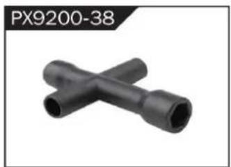
natural_image
Two black X-shaped pipe fittings (no text or symbols visible)Socket Wrench
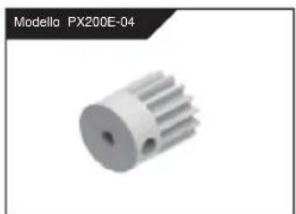
natural_image
3D model of a mechanical gear component (no text or symbols visible)natural_image
3D model of a heat sink or cooling element with radial fins, no text or symbols visiblenatural_image
Group of metallic screw-like components arranged in two rows (no text or symbols visible)Φ2.6*7PB Round Head Screw
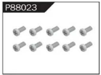
natural_image
Group of identical metallic screw-like components arranged in two rows (no text or symbols visible)Φ2.6*10PB Round Head Screw
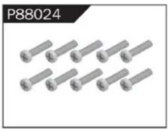
natural_image
Group of eight identical metallic bolts arranged in two rows (no text or symbols visible)Φ2.6*30PB Round Head Screw
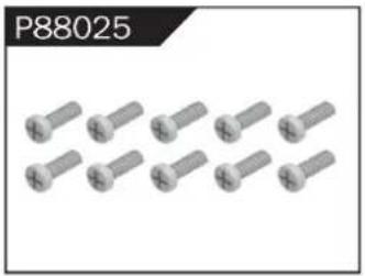
natural_image
Group of metallic screw-like components arranged in two rows (no text or symbols visible)Φ3*12 Round Head Screw
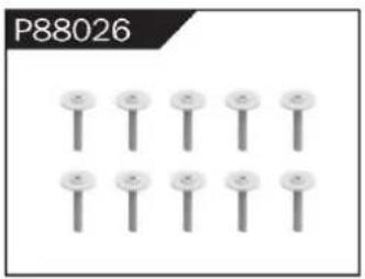
natural_image
Grid of nine identical screw-like components arranged in two rows (no text or symbols)Φ2.3*10PB Screw
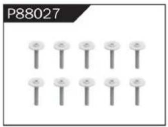
natural_image
Grid of nine identical screw-like components arranged in two rows (no text or symbols visible)Φ2.6*12PB Screw
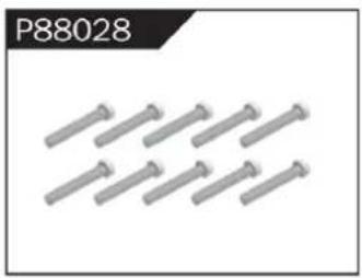
natural_image
Group of metallic bolts arranged in a row (no text or symbols visible)Φ1.7*8PB Screw
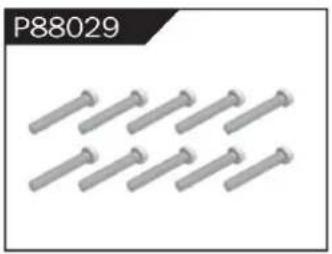
natural_image
Row of metallic screwdrivers arranged in two rows (no text or symbols visible)Φ2*8PB Screw
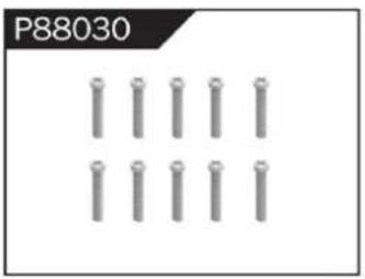
natural_image
Grid of metallic cylindrical pins arranged in three rows (no text or symbols)Φ2.3*14PB Screw
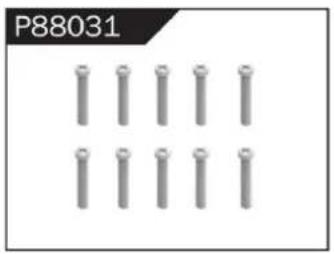
natural_image
Grid of metallic cylindrical pins arranged in three rows (no text or symbols visible)Φ2.6*14PB Screw
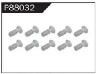
natural_image
Group of identical screwdrivers arranged in two rows (no text or symbols visible)Φ2.6*10 Flattened Head Screw
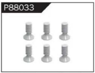
natural_image
Six identical screw-like components arranged in two rows (no text or symbols visible)Φ3*8 Flattened Head Machine Screw
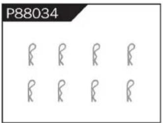
Body Clip
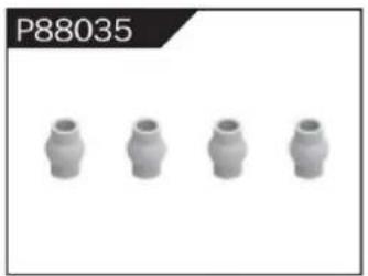
natural_image
Four identical cylindrical mechanical parts arranged horizontally (no text or symbols visible)Hollow Ball Connectors
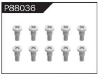
Step Screw
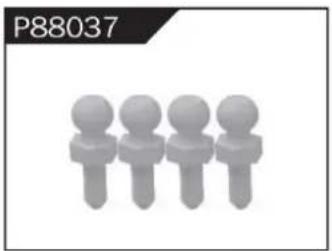
natural_image
Four stylized human figures in a row, no text or symbols presentΦ4.8 Ball Head
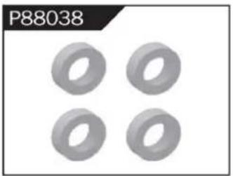
natural_image
Four identical gray toroidal components arranged in a 2x2 grid (no text or symbols)Φ10*15*4 Ball Bearing
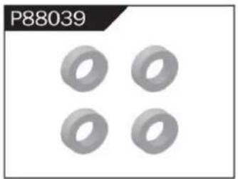
natural_image
Four gray ring-shaped objects arranged in a 2x2 grid (no text or symbols)Φ8*10*3 Ball Bearing
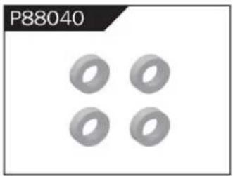
natural_image
Four identical gray ring shapes arranged in a 2x2 grid (no text or symbols)Φ5*9*3 Ball Bearing
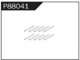
Φ1.5*10 Wheel Hex Pin c
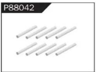
natural_image
Pure electrical circuit lines without any symbolsΦ2.5*26.5 Steering Pin B
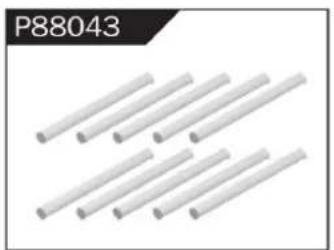
natural_image
Close-up of white cylindrical rods arranged in a diagonal pattern (no text or symbols visible)Φ3*48 Front/Rear Lower Suspension Pin A
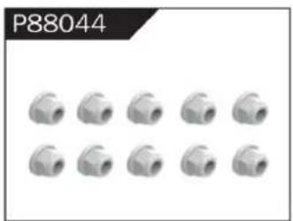
natural_image
Grid of 12 identical mechanical pipe fitting units, no text or symbols visibleNylor Nut M4

natural_image
12 gray hexagonal nuts arranged in two rows (no text or symbols visible)Wheel Hex
WARNINGS
- According to the instructions provided on the manual. Some part needs to be assembled and adjusted by adults.
- Please use under the guidance of an adult.
- Please promptly put away the packing materials so as not to cause harm to children.
- Do not operate on a location where water is trapped or under the rain. Parts of the product may malfunction if exposed to water.
- Do not touch the rotating wheel to avoid injury.
- The product contains small parts that may pose a risk of ingestion or suffocation.
- To remotely control the product on the road or in a crowd to avoid accidents.
- It is necessary to periodically check the charging USB cable, plug, housing and other components, and immediately unplug if found to be damaged.
- This product can only use the factory configured USB cable to charge the product battery.
- USB cable, battery box, and battery must be inserted into the same specified power supply as the product symbol.
- The USB charging cable and the battery is not a toy.
- Disconnect the rechargeable USB cable before cleaning the toy.
- If you observe electrical charges during product usage, turn off the device immediately.
- When installing or replacing the battery, pay attention to the correct polarity of the battery.
- The remote control car uses a 7.4V Lithium battery.
- It is strictly prohibited do the following actions such as but not limited to disassemble, modify, crash, puncture, drop, throw in a fire or any other means of causing damage to the product to avoid harm to the user and other participants.
- Do not expose the battery to prolonged exposure to sunlight to prevent danger.
- It is advisable to store the battery at a temperature below 30^ C. Do not store it in a place with heat, high temperature, or humidity to avoid danger.
- Non-rechargeable batteries cannot be charged.
- When charging a rechargeable battery, adult supervision is required.
- The rechargeable battery should be removed from the toy before charging.
- Do not mix old and new or different types of batteries.
- Only use the USB cable configured by this product when charging the battery.
- Do not disassemble the battery or modify the battery to avoid risk of fire or explosion.
- After the battery is used, it should be taken out of the remote control car. After cooling the battery, you can then charge it and placed it on a safe location. Unplug the battery outlet from the USB charging cable when not in used and disconnect the power line.
- Stop using the battery as soon as it gives a foul smells or suddenly becomes hot, deformed, discolored, or otherwise abnormal during use or charging.
- After the battery of the remote controller runs out, battery temperature is usually high and would recommend to wait for
30 minutes before charging the battery again. Otherwise, it may damage the battery. - Drained batteries should be removed immediately.
- Do not cause the electrical supply of the wiring port to short circuit.
- If you do not use the product for a long time, remove the batteries of the remote control car and remote control.
- instructions contains important product information, please give time to read for better product experience.
GENERAL INFORMATION
CAN NMB-3 (B)
RF Exposure
Radiation Exposure Statement:
This equipment complies with IC radiation exposure limits set forth for an uncontrolled environment. This equipment should be installed and operated with minimum distance 20cm between the radiator & your body.
BATTERY WARNING:
- Failure to follow all the instructions may result in serious injury, irreparable damage to the battery and may cause a fire, smoke or explosion.
- Always check the battery's condition before charging or using it.
- Replace the battery if damaged, gives a foul odor or show signs of overheating, discoloration, deformation and leakage.
- Never use anything other than the approval charger the battery. Always use a balancing charger for battery. It is recommended that you do not to use any other charger than the one provided with the product.
- The battery temperature must never exceed 60°C (140°F) otherwise the battery could be damaged or ignite.
- Never charge on a flammable surface, near flammable products or inside a vehicle (perferably place the battery in a non-flammable and nonconductive container).
- Never leave the battery unattended during the charging process. Never disassemble or modify the housing's wiring, or puncture the cells. Always ensure that the charger output voltage corresponds to the voltage of the battery. Do not overcharge the batter that may cause short circuit.
- Never expose the battery to moisture or direct sunlight, or store it in a place where temperatures could exceed 60^ C (car in the sun, for example).
- Always keep it out of reach from children.
- Improper battery use may result in a fire, explosion or other hazard.
- Non-rechargeable batteries are not be charge again. Rechargeable batteries are only to be charged with the supervision of an adult.
- Different types of batteries or new or used batteries which are different are not be mixed.
- Batteries are to be inserted with the correct polarity.
- The supply terminal should be used well to avoid short circuit. Examination of the transformer and battery charger regularly is encouraged to check any damage in the cord, plug, enclosure and other parts. If damage is observed, it must not be used until it has been repaired.
- The packaging has to be kept since it contains important information.
- The toy is only to be connected to Class II equipment bearing the symbol.
C/O YH Consulting Limited Ufficio 147, Centurion House, London Road, Staines-upon-Thames, Surrey, TW18 4AX
Importato in AUS: SIHAO PTY LTD.
1 ROKEVA STREET EASTWOOD NSW 2122 Australia
Suite 250, 9166 Anaheim Place, Rancho Cucamonga, CA 91730
VEVOR®
TOUGH TOOLS, HALF PRICE
elettronica www.vevor.com/support
VEVOR®
TOUGH TOOLS, HALF PRICE
natural_image
Top-down view of a black and yellow heavy-duty toy car with four large tires, parked on a concrete floor (no visible text or symbols)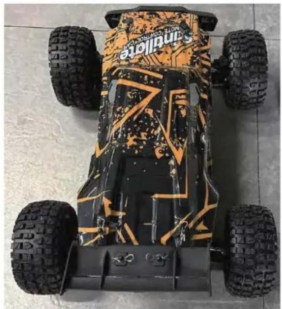
natural_image
Top-down view of a Sandville electric vehicle with four tires and camouflage pattern (no visible text or symbols)206E
To make your experience with this remote control car as easy and convenient as possible, please read the instructions provided before using the product. Enjoy and have fun with the product while keeping the manual for future maintenance and reference.
- In order to protect the legitimate rights and interests of users, please be sure to carefully read the contents of this manual before using this product.
- When using this product, please be sure to strictly observe and perform the requirements which includes but not limited to the instructions and safety guidelines. For any personal injury, accident, property loss, legal dispute, or any other adverse event causing a conflict of interest resulting from the use of the product or any irresistible factors that are in violation of the safety instructions, the user shall bear the related responsibilities and losses.
- Once you start using the product, you are deemed to have read, understood, recommended, and accepted all terms and contents of the instructions (including disclaimers, safety instructions, warning instructions, etc.) included with this product.
- In case you are having challenges on any aspect of the product, may it be operation or maintenance, please contact your local sales agent
PACKAGE CONTENTS
| | | | | |
| RC Car | Remote Control | USB de 7,4 V | LI-PO de 7,4 V | Product Manual | Accessory package |
CHARGING
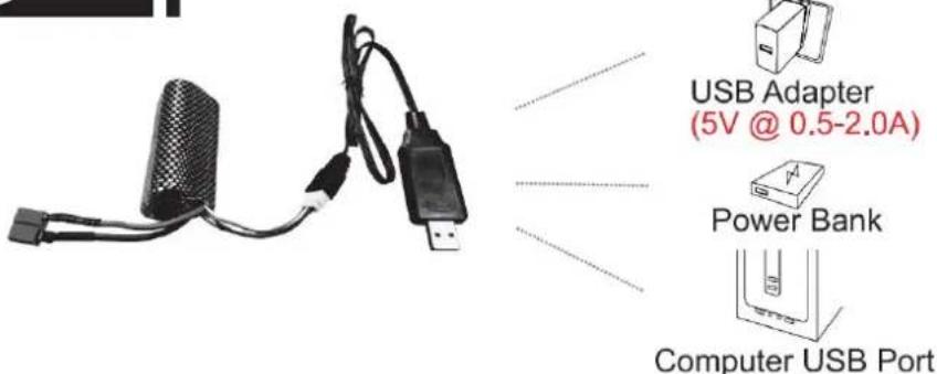
The battery isn't fully charged when it's made. When the car battery low, the car will start the LVC (Low Voltage Cutoff) protection function to protect the battery, the car can only turn, not forward and backward. Please charge the battery.
- Plug the USB charging cable into the USB charging port of the computer, power bank or USB adapter (5V@0.5\~2.0A).
- Connect the battery wire to the USB charging cable.
- Charging time: about 250 minutes.
- The green indicator light on the USB charging cable will flash when it is charging and will turn sólido once fully charged.
ATTENTION:
- Please keep the battery in sight when charging. DO NOT put the battery on a flammable surface.
- If battery pack and USB charging cable are damaged, immediately stop using it and replace the accessories as soon as possible.
RC CAR'S DETAILS
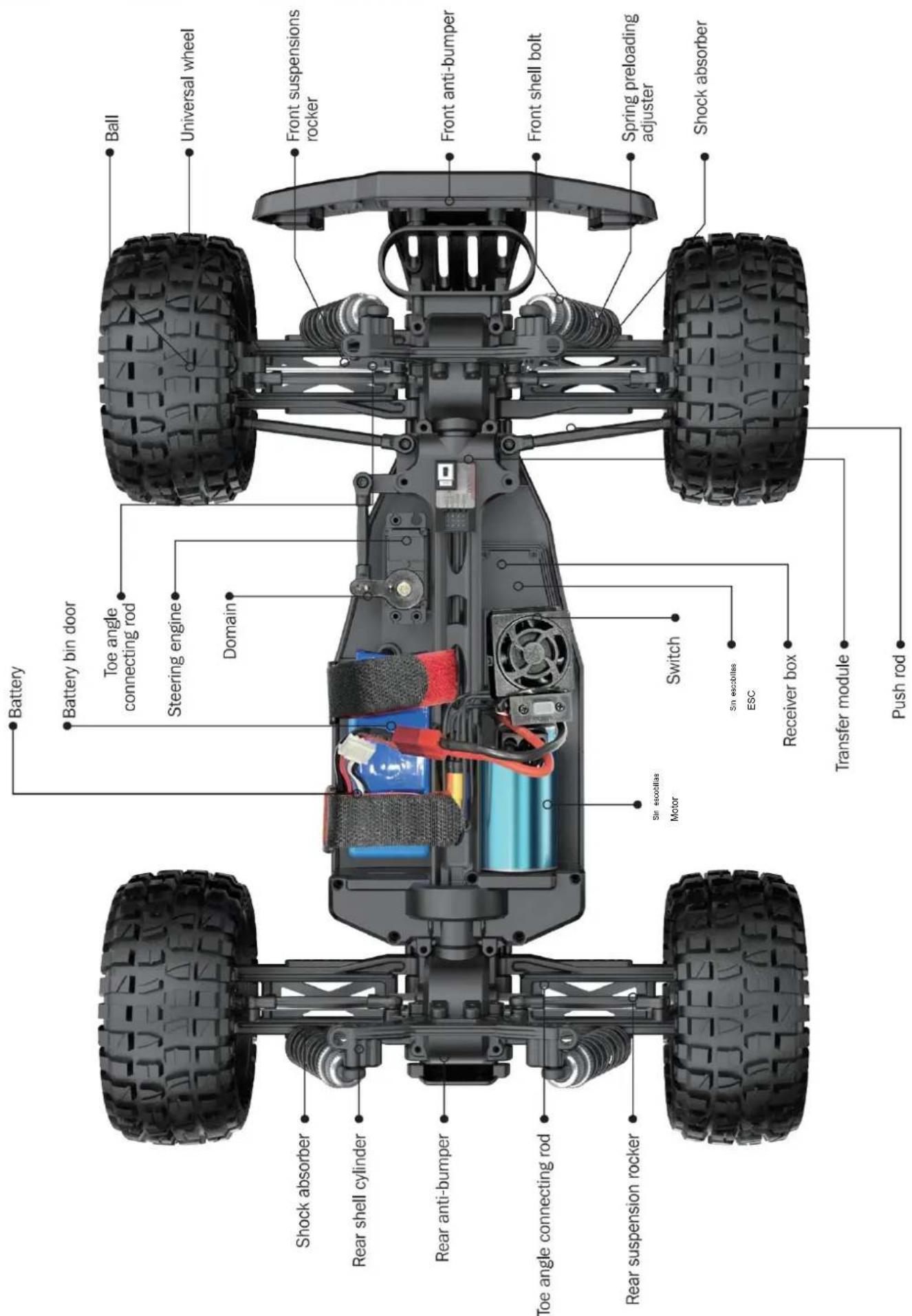
BATTERY INSTALLATION
REMOTE CONTROLLER
Our company has configured a new remote control for the model, Please ready the operation on the instruction manual carefully. Below is the functions description of this remote control.
■ Remote Control 1
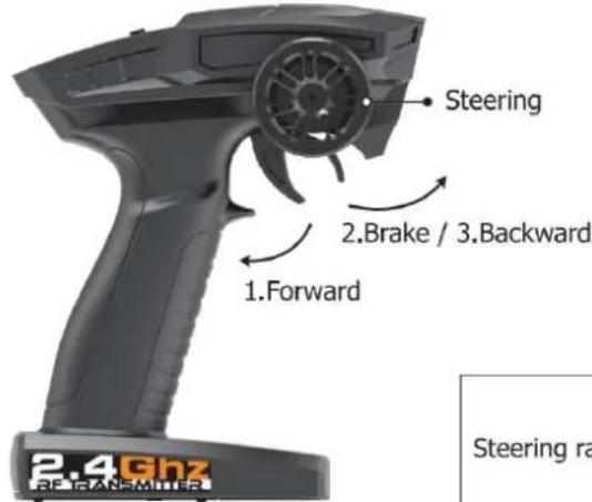
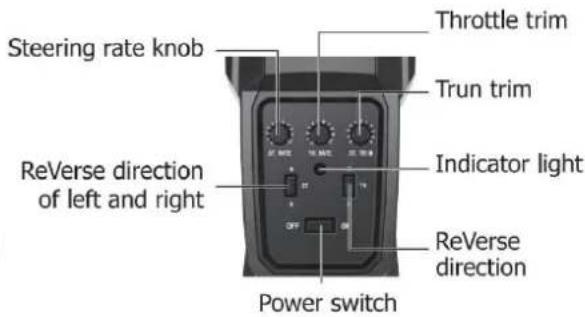
Remote Control 2
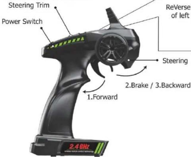
Steering rate knob
Reverse direction of left and right
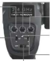
Throttle trim
Trun trim
Indicator light
ReVerse direction
Steering
2.Brake / 3.Backward
2.4GHz
- When the trigger is pulled back, the vehicle advances
- When the vehicle is moving forward, push the trigger forward and the vehicle will brake;
- When the trigger on the remote control returns to the midpoint, push the trigger forward again and the vehicle will retreat.
| LED color/pattern | Name | Hints |
| Red light always on | Normal driving pattern | |
| Red light with slow flash (on at 0.5s/off at 0.5s) | Hint of low power | For more information m please refer to operation of putting new battery into remote on page 6. |
| Red light with quick flash (on at 0.125s/off at 0.125s) | Connect failed/error | If transmitter and receiver are bound unsuccessfully, please close the remote system and restart for recovering normal operation. Please check exceeding scope, low battery or damaged antenna if the connection is failed. |
OPERATION
RC CAR BATTERY
① Take out the clip and open the battery cover.
② Connect the battery outlet to the cable in the battery compartment, then insert the battery to the batter compartment.
③ Close the battery cover and lock it.
If the car will not be used for a long time, make sure to turn it off and remove the battery.
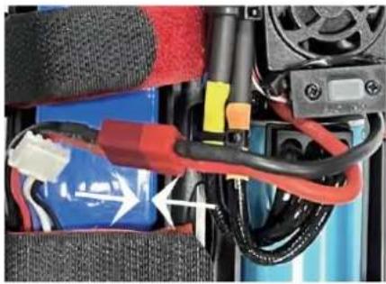
natural_image
Close-up of a battery pack with red and blue wires, no visible text or symbolsREMOTE CONTROL BATTERY
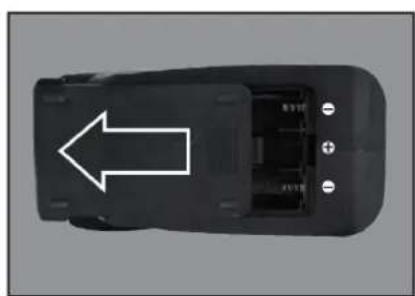
natural_image
Top-down view of a black car component with a white arrow pointing to the side (no text or symbols visible)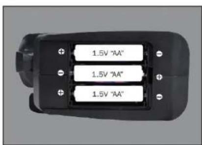
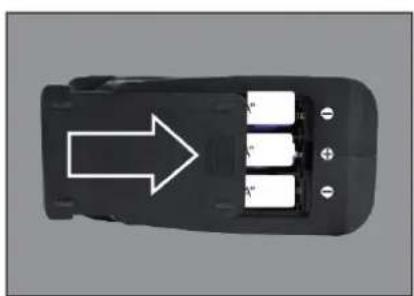
natural_image
Top-down view of a black car interior with three battery cells and an arrow pointing to one (no text or symbols)① Push the battery cover out.
② Insert 3 AA batteries (not included) in the correct direction.
③ Push the battery cover in.
If the remote will not be used for a long time, make sure to turn it off and remove the batteries.
When the battery of the remote control is low, the indicator light of the remote control will flash slowly.
OPERATION
PAIRING
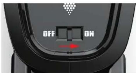
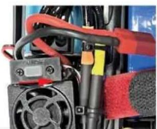
natural_image
Close-up of a mechanical assembly with red and black components, no visible text or symbols① Make sure the battery is charged.
② Insert batteries to the car and the remote.
③ Turn on the car power switch and the remote power switch. (DO NOT pull the throttle trigger during pairing)
④ Both will automatically pair. (The remote power indicator and the car power indicator will flash while waiting for the pairing process and will turn solid once pairing has been successful)
FREQUENTLY ASKED QUESTIONS
FORWARD, REVERSE, TURN LEFT, TURN RIGHT

Pull the throttle trigger backward, the car goes forward. Push the throttle trigger forward, the car brakes, then push the throttle trigger forward again, the car goes reverse. (The throttle controls the speed)
Turn the steering control wheel counterclockwise, the car turns left. Turn the steering control wheel clockwise, the car turns right. ( Control the Steering Wheel Rotation Angle can control the degree of turning )
MAXIMUM SPEED CONTROL
Steering Rate Knob
Use the Steering Rate Knob to adjust direction angle when the steering wheel operated.
Increase the steering angle
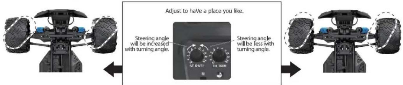
FINE TUNING KNOB OF STEERING
Use throttle to adjust the speed into your ideal one by rotate left or rotate right
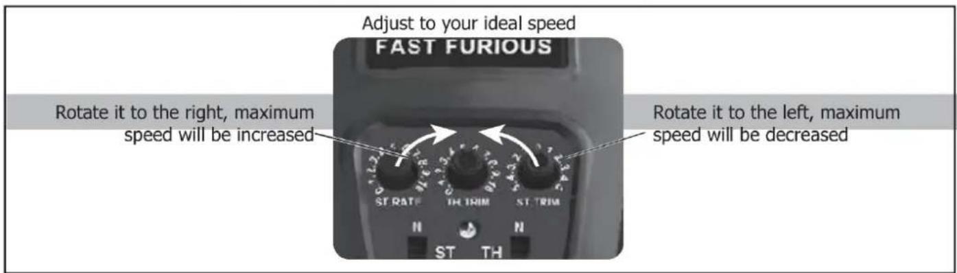
| QUESTION | CAUSE | SOLUTION |
| No match or can't control it | 1. The car battery or remote control battery is completely dead2. Out of remote range | 1. Replace charged battery2. Repair and keep in remote distance |
| Can't go forward or reverse | 1. Low battery2. The car shorted out when it got wet3. Poor contact between motor and electronic regulator | 1. Charging2. Let the car dry completely3. Reconnect the connection wire between the motor and the electronic regulator |
| Can't turn left or turn right | 1. The steering angle knob(ST.RATE) is set to minimum2. Low battery3. The car shorted out when it got wet3. Poor contact between steering gear and electronic regulator | 1. Set the steering angle knob (ST.RATE) to maximum2. Charging3. Let the car dry completely4. Reconnect the connection wire between the steering gear and the electronic regulator |
| It won't charge | 1. The output voltage or current of the power supply is too high2. The charging cable or battery is broken | 1. The output voltage and current of the power supply should be 5V0.5~2A2. Contacte con el servicio de atención al cliente |
| Something's missing or broken | Contactar con Atención al Cliente | |
| The wheels turn on their own | Pull the throttle trigger during pairing | Repair without pulling the throttle |
SPECIFICATIONS
Motor:
Battery:
Remote frequency:
Remote distance:
Charging mode:
7.4 V lithium battery
2.4GHz
100m
USB balance charging cable
DEVICE EXPLOSION DIAGRAM
9200 ASSEMBLY VIEW
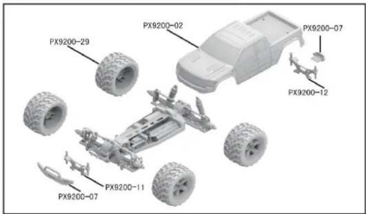
9203 ASSEMBLY VIEW
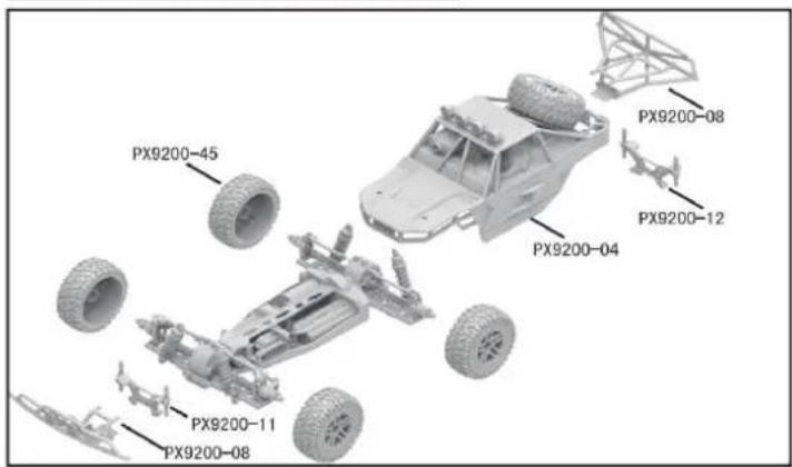
9204 CAR BOBY
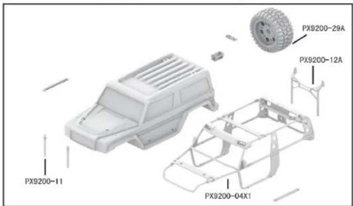
DRIVE AXLE EXPLODED VIEW
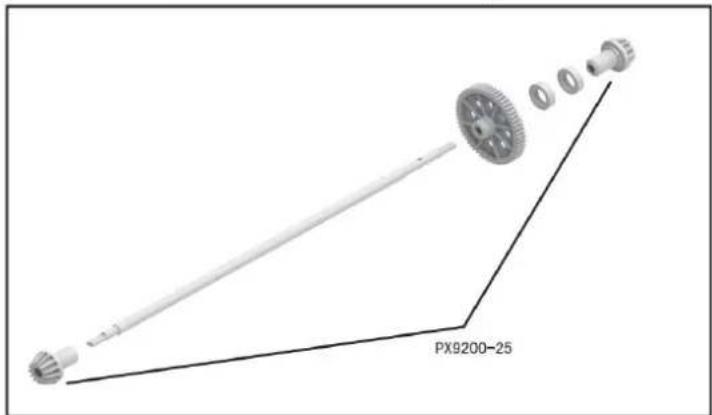
9202 ASSEMBLY VIEW
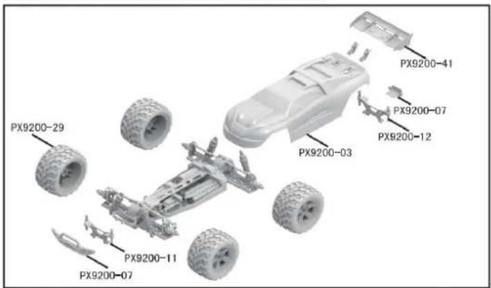
9203 CAR BOBY
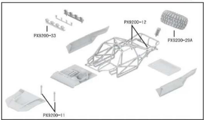
FRONT & REAR DIFFERENTIAL EXPLODED VIEW
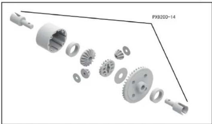
natural_image
Exploded view diagram of a mechanical gear assembly (no text or symbols)TIRE & WHEEL AXLE EXPLODED VIEW
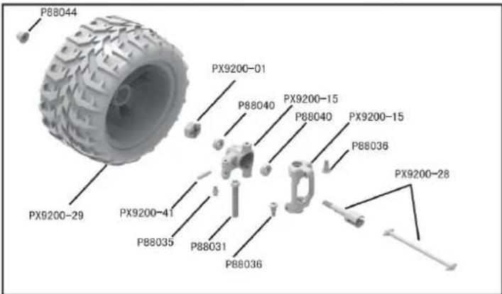
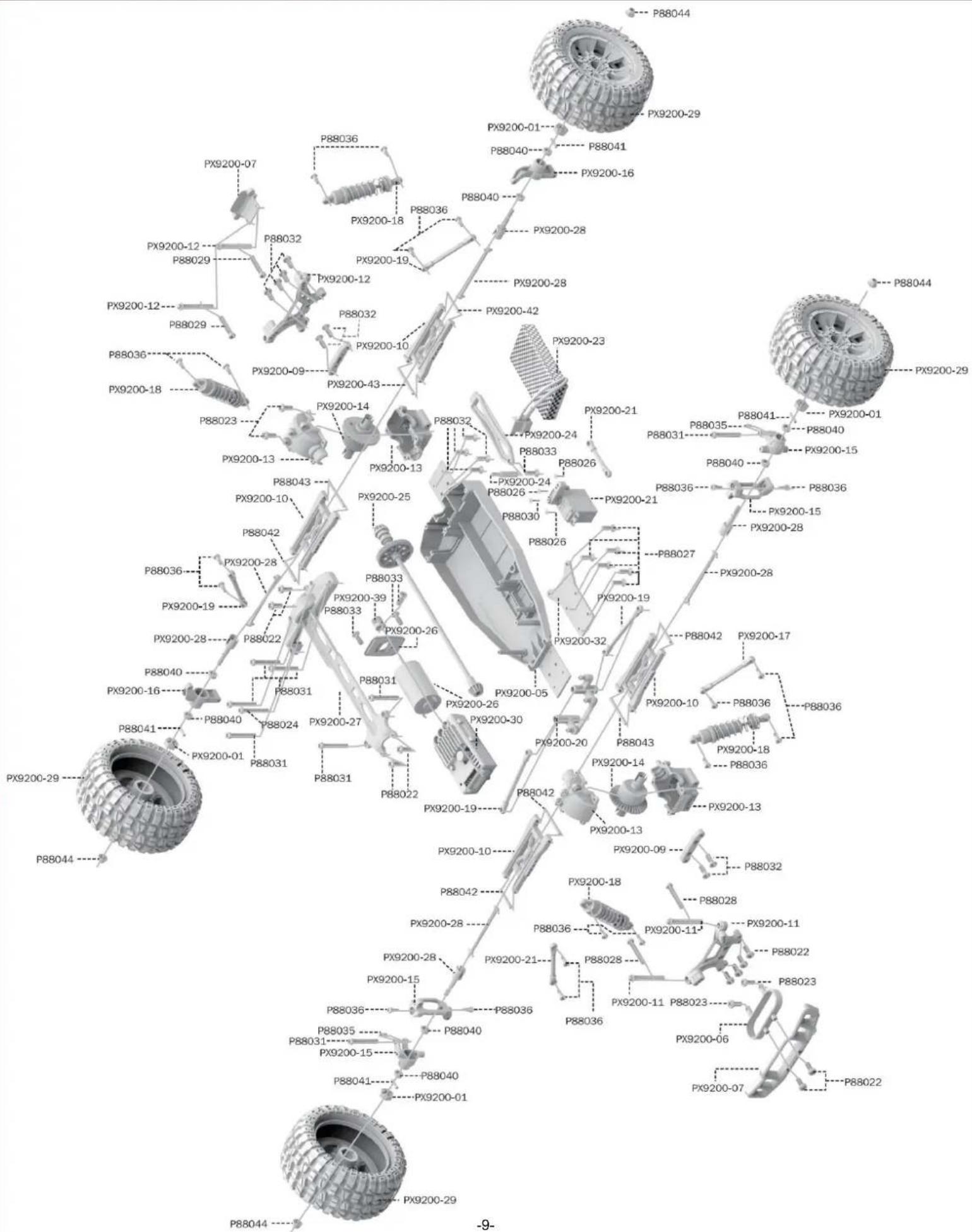
RETAIL ACCESSORY VIEW
PX9200-22
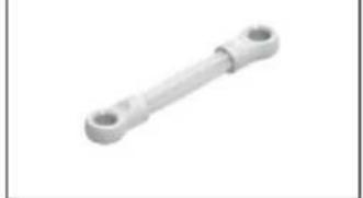
natural_image
Metal mechanical component with two circular ends (no text or symbols visible)Servo Link
PX9200-05
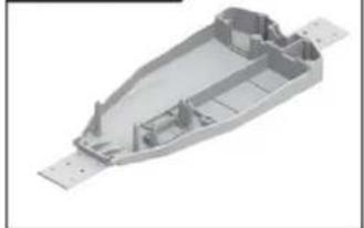
natural_image
3D rendering of a mechanical housing component with visible internal ribs and mounting holes (no text or symbols)Chassis
PX9200-06
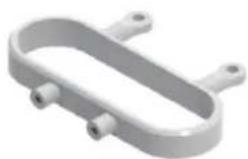
natural_image
3D rendering of a U-shaped mechanical component with two side ports (no text or symbols)Tube-style bumpers
PX9200-07
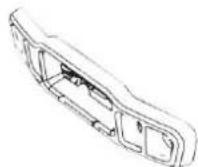
9200-Front/Rear Bumper
PX9200-09
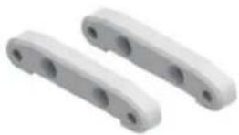
Tie Bar
PX9200-10
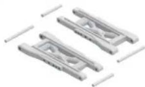
natural_image
Three identical mechanical clamping components with no visible text or symbolsLower Supension Arm
PX9200-11
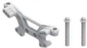
natural_image
Mechanical assembly with two screws and a bracket (no text or symbols visible)Front Shock Tower and Body Post
PX9200-08
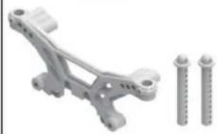
natural_image
Mechanical component with two screws and a bracket, no visible text or symbolsRear Shock Tower and Body Post
PX9200-13
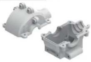
natural_image
Two white plastic mechanical housing components, one open and one closed, with no visible text or markings.Front/Rear Gear Box
PX9200-14
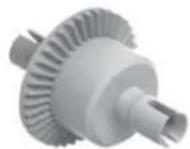
Diff Main Gear Complete
PX9200-15
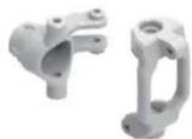
Front Steering Carrier
PX9200-16
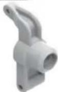
Rear Upright
PX9200-17
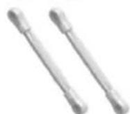
Front/Rear Upper Link
PX9200-18
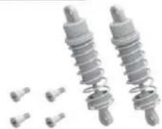
natural_image
Two metallic spring components with bolts and small pins, no text or symbols visibleFront/Rear Shock Absorber
PX9200-19
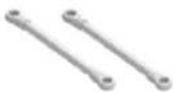
Steering Link
PX9200-20
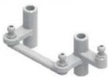
Steering Arm Complete
PX9200-51
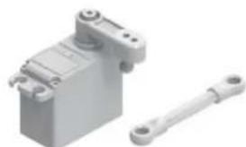
natural_image
3D rendering of a mechanical device with a shaft and housing (no text or symbols visible)Servo (3 cables)
RETAIL ACCESSORY VIEW
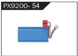
natural_image
Blue battery with red connector and wire, labeled PX9200-54 (no other text or symbols)LIPO Battery (7.4V 4000MAH)
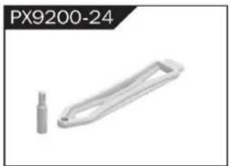
natural_image
3D rendered mechanical part with a cylindrical end and a rectangular handle (no text or symbols visible)Battery Cover
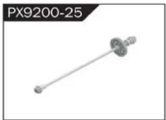
natural_image
Mechanical component labeled PX9200-25, showing a shaft with flanged ends and a central hub (no text or symbols on the part itself)Drive Shaft Assembly
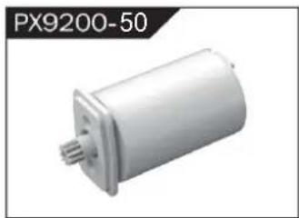
natural_image
Exterior view of a white cylindrical mechanical component (no text or symbols visible)Sin escobillas Motor
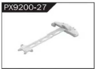
natural_image
Mechanical component labeled PX9200-27, showing a rod-like structure with mounting holes (no text or symbols on the object itself)Motor Layering
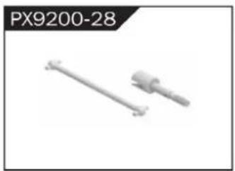
natural_image
Two mechanical components, one straight and one cylindrical, shown without any text or symbols.Universal Drive Joint

natural_image
3D rendered tire component labeled PX9200-29A, showing textured surface and mounting holes (no text or symbols on the object itself)Vacuum Wheel Complete
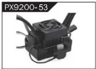
natural_image
Close-up of a black industrial device with cooling fan and cooling fins (no visible text or symbols)ESC
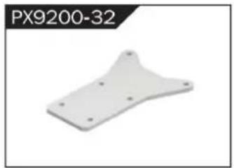
natural_image
3D model of a white plastic mechanical part with mounting holes (no text or symbols visible)Chassis Sheet Steel
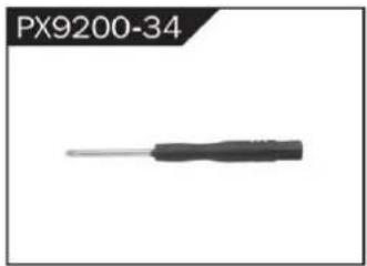
natural_image
Close-up of a black screwdriver with a metallic tip, labeled PX9200-34 (no other text or symbols visible)3MM Crosstip Screwdrivers
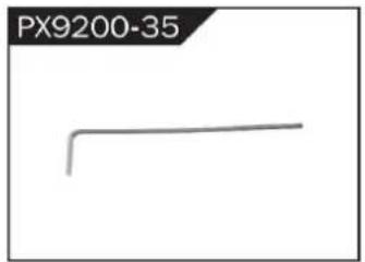
natural_image
Simple line drawing of a bent pipe or rod (no text or symbols)2MM Hexagon Wrench
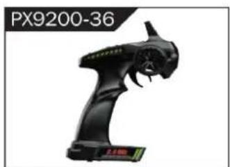
natural_image
Black handheld device labeled PX9200-36, showing a stylized creature with no visible text or symbols on the device itself.I 2.4G Transmitter for all

II 2.4G Transmitter for all
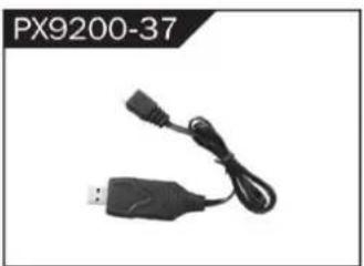
natural_image
Black USB and cable connector with a connector, labeled PX9200-37 (no other text or symbols visible)7,4 V- USB
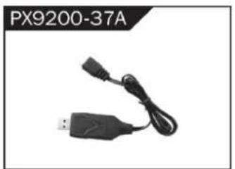
natural_image
Black USB device with attached cable and connector, labeled PX9200-37A (no other text or symbols visible)11,1 V- USB
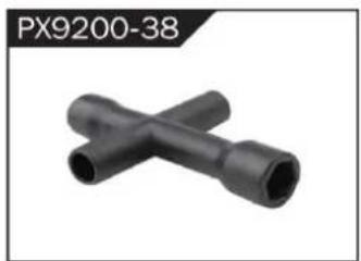
natural_image
Two black X-shaped pipe fittings (no text or symbols visible)Socket Wrench
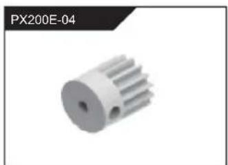
natural_image
3D rendered image of a white mechanical gear or rotor component (no text or symbols visible)natural_image
Metallic heat sink component with radial fins, no visible text or symbolsResistente al calor del motor
Cubrir
RETAIL ACCESSORY VIEW
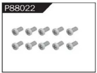
natural_image
Group of metallic screw-like components arranged in two rows (no text or symbols visible)Φ2.6*7PB Round Head Screw
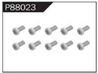
natural_image
Group of identical metallic screw-like components arranged in two rows (no text or symbols visible)Φ2.6*10PB Round Head Screw
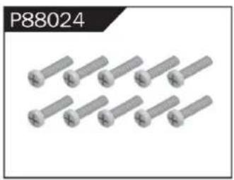
natural_image
Group of eight identical metallic bolts arranged in two rows (no text or symbols visible)Φ2.6*30PB Round Head Screw
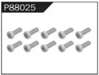
natural_image
Group of metallic screw-like components arranged in two rows (no text or symbols visible)Φ3*12 Round Head Screw
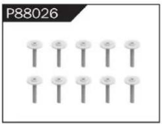
natural_image
Grid of nine identical screw-like components arranged in two rows (no text or symbols)Φ2.3*10PB Screw
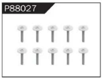
natural_image
Grid of nine identical screw-like components arranged in two rows (no text or symbols)Φ2.6*12PB Screw
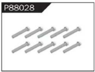
natural_image
Group of metallic bolts arranged in a row (no text or symbols visible)Φ1.7*8PB Screw

natural_image
Row of metallic screwdrivers arranged in two rows (no text or symbols visible)Φ2*8PB Screw
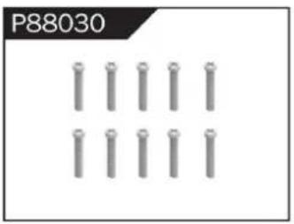
natural_image
Grid of metallic cylindrical pins arranged in three rows (no text or symbols)Φ2.3*14PB Screw
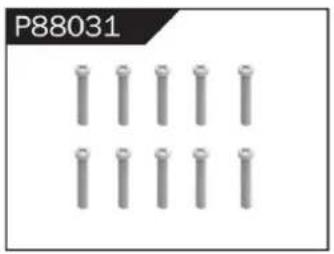
natural_image
Grid of metallic cylindrical pins arranged in three rows (no text or symbols visible)Φ2.6*14PB Screw
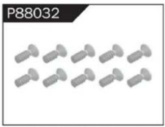
natural_image
Group of identical screwdrivers arranged in two rows (no text or symbols visible)Φ2.6*10 Flattened Head Screw
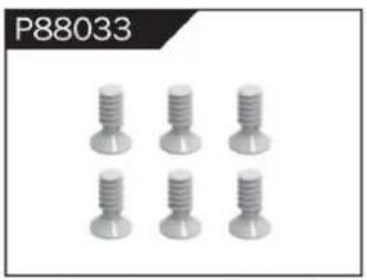
natural_image
Six identical screw-like components arranged in two rows (no text or symbols visible)Φ3*8 Flattened Head Machine Screw
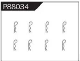
Body Clip
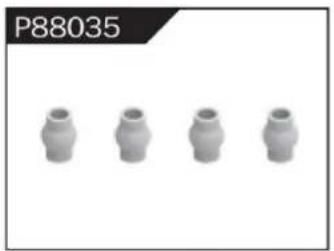
natural_image
Four identical cylindrical mechanical components arranged horizontally (no text or symbols visible)Hollow Ball Connectors
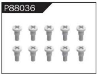
Step Screw
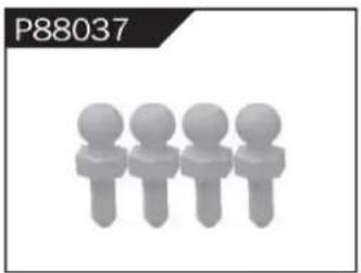
natural_image
Four stylized human figures in a row, no text or symbols presentΦ4.8 Ball Head
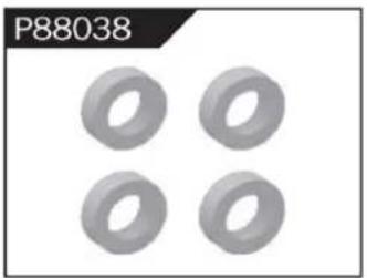
natural_image
Four identical gray toroidal components arranged in a 2x2 grid (no text or symbols)Φ10*15*4 Ball Bearing
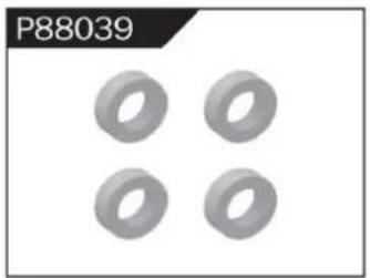
natural_image
Four identical gray ring shapes arranged in a 2x2 grid on a white background (no text or symbols)Φ8*10*3 Ball Bearing
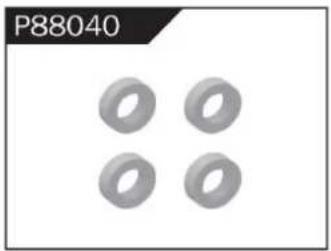
natural_image
Four identical gray ring shapes arranged in a 2x2 grid (no text or symbols)Φ5*9*3 Ball Bearing
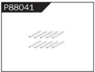
Φ1.5*10 Wheel Hex Pin c
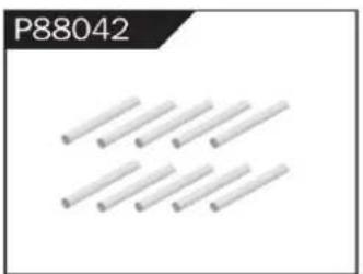
natural_image
Pure electrical circuit lines without any symbolsΦ2.5*26.5 Steering Pin B
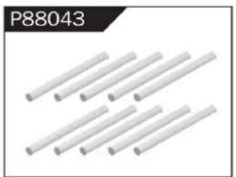
natural_image
Six white cylindrical rods arranged diagonally (no text or symbols visible)Φ3*48 Front/Rear Lower Suspension Pin A
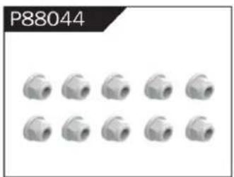
natural_image
Grid of 12 identical mechanical pipe fitting units, no text or symbols visibleNylor Nut M4
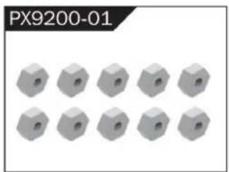
natural_image
12 gray hexagonal nuts arranged in two rows (no text or symbols visible)Wheel Hex
WARNINGS
- According to the instructions provided on the manual. Some part needs to be assembled and adjusted by adults.
- Please use under the guidance of an adult.
- Please promptly put away the packing materials so as not to cause harm to children.
- Do not operate on a location where water is trapped or under the rain. Parts of the product may malfunction if exposed to water.
- Do not touch the rotating wheel to avoid injury.
- The product contains small parts that may pose a risk of ingestion or suffocation.
- To remotely control the product on the road or in a crowd to avoid accidents.
- It is necessary to periodically check the charging USB cable, plug, housing and other components, and immediately unplug if found to be damaged.
- This product can only use the factory configured USB cable to charge the product battery.
- USB cable, battery box, and battery must be inserted into the same specified power supply as the product symbol.
- The USB charging cable and the battery is not a toy.
- Disconnect the rechargeable USB cable before cleaning the toy.
- If you observe electrical charges during product usage, turn off the device immediately.
- When installing or replacing the battery, pay attention to the correct polarity of the battery.
- The remote control car uses a 7.4V Lithium battery.
- It is strictly prohibited do the following actions such as but not limited to disassemble, modify, crash, puncture, drop, throw in a fire or any other means of causing damage to the product to avoid harm to the user and other participants.
- Do not expose the battery to prolonged exposure to sunlight to prevent danger.
- It is advisable to store the battery at a temperature below 30^ C. Do not store it in a place with heat, high temperature, or humidity to avoid danger.
- Non-rechargeable batteries cannot be charged.
- When charging a rechargeable battery, adult supervision is required.
- The rechargeable battery should be removed from the toy before charging.
- Do not mix old and new or different types of batteries.
- Only use the USB cable configured by this product when charging the battery.
- Do not disassemble the battery or modify the battery to avoid risk of fire or explosion.
- After the battery is used, it should be taken out of the remote control car. After cooling the battery, you can then charge it and placed it on a safe location. Unplug the battery outlet from the USB charging cable when not in used and disconnect the power line.
- Stop using the battery as soon as it gives a foul smells or suddenly becomes hot, deformed, discolored, or otherwise abnormal during use or charging.
- After the battery of the remote controller runs out, battery temperature is usually high and would recommend to wait for
30 minutes before charging the battery again. Otherwise, it may damage the battery. - Drained batteries should be removed immediately.
- Do not cause the electrical supply of the wiring port to short circuit.
- If you do not use the product for a long time, remove the batteries of the remote control car and remote control.
- instructions contains important product information, please give time to read for better product experience.
GENERAL INFORMATION
CAN NMB-3 (B)
RF Exposure
Radiation Exposure Statement:
This equipment complies with IC radiation exposure limits set forth for an uncontrolled environment. This equipment should be installed and operated with minimum distance 20cm between the radiator & your body.
BATTERY WARNING:
- Failure to follow all the instructions may result in serious injury, irreparable damage to the battery and may cause a fire, smoke or explosion.
- Always check the battery's condition before charging or using it.
- Replace the battery if damaged, gives a foul odor or show signs of overheating, discoloration, deformation and leakage.
- Never use anything other than the approval charger the battery. Always use a balancing charger for battery. It is recommended that you do not to use any other charger than the one provided with the product.
- The battery temperature must never exceed 60°C (140°F) otherwise the battery could be damaged or ignite.
- Never charge on a flammable surface, near flammable products or inside a vehicle (perferably place the battery in a non-flammable and nonconductive container).
- Never leave the battery unattended during the charging process. Never disassemble or modify the housing's wiring, or puncture the cells. Always ensure that the charger output voltage corresponds to the voltage of the battery. Do not overcharge the batter that may cause short circuit.
- Never expose the battery to moisture or direct sunlight, or store it in a place where temperatures could exceed 60^ C (car in the sun, for example).
- Always keep it out of reach from children.
- Improper battery use may result in a fire, explosion or other hazard.
- Non-rechargeable batteries are not be charge again. Rechargeable batteries are only to be charged with the supervision of an adult.
- Different types of batteries or new or used batteries which are different are not be mixed.
- Batteries are to be inserted with the correct polarity.
- The supply terminal should be used well to avoid short circuit. Examination of the transformer and battery charger regularly is encouraged to check any damage in the cord, plug, enclosure and other parts. If damage is observed, it must not be used until it has been repaired.
- The packaging has to be kept since it contains important information.
- The toy is only to be connected to Class II equipment bearing the symbol.
C/O YH Consulting Limited Oficina 147, Centurion House, London Road,
Staines-upon-Thames, Surrey, TW18 4AX
Importado a AUS: SIHAO PTY LTD.
1 ROKEVA STREET EASTWOOD NSW 2122 Australia
Suite 250, 9166 Anaheim Place, Rancho Cucamonga, CA 91730
VEVOR®
TOUGH TOOLS, HALF PRICE
natural_image
Top-down view of a black and yellow heavy-duty toy car with four large tires, parked on a concrete floor (no visible text or symbols)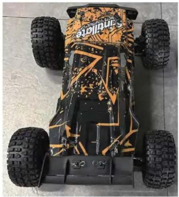
natural_image
Top-down view of a Sandstone off-road vehicle with camouflage pattern and visible tires (no text or symbols)206E
POTRZEBUJESZ POMOCY? SKONTAKTUJ SIĘ Z NAMI!
To make your experience with this remote control car as easy and convenient as possible, please read the instructions provided before using the product. Enjoy and have fun with the product while keeping the manual for future maintenance and reference.
- In order to protect the legitimate rights and interests of users, please be sure to carefully read the contents of this manual before using this product.
- When using this product, please be sure to strictly observe and perform the requirements which includes but not limited to the instructions and safety guidelines. For any personal injury, accident, property loss, legal dispute, or any other adverse event causing a conflict of interest resulting from the use of the product or any irresistible factors that are in violation of the safety instructions, the user shall bear the related responsibilities and losses.
- Once you start using the product, you are deemed to have read, understood, recommended, and accepted all terms and contents of the instructions (including disclaimers, safety instructions, warning instructions, etc.) included with this product.
- In case you are having challenges on any aspect of the product, may it be operation or maintenance, please contact your local sales agent
PACKAGE CONTENTS
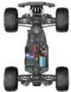 | 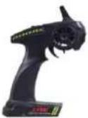 | 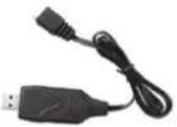 | 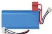 |  |  |
| RC Car | Remote Control | 7,4 V USB | 7,4 V LI-PO | Product Manual | Accessory package |
CHARGING
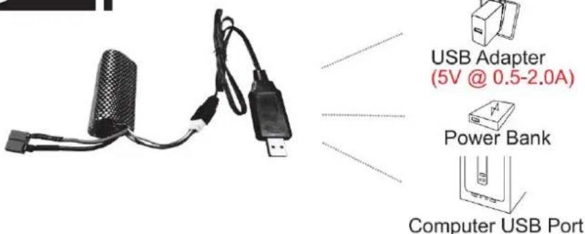
The battery isn't fully charged when it's made. When the car battery low, the car will start the LVC (Low Voltage Cutoff) protection function to protect the battery, the car can only turn, not forward and backward. Please charge the battery.
- Plug the USB charging cable into the USB charging port of the computer, power bank or USB adapter (5V@0.5\~2.0A).
- Connect the battery wire to the USB charging cable.
- Charging time: about 250 minutes.
- The green indicator light on the USB charging cable will flash when it is charging and will turn solidny once fully charged.
ATTENTION:
- Please keep the battery in sight when charging. DO NOT put the battery on a flammable surface.
- If battery pack and USB charging cable are damaged, immediately stop using it and replace the accessories as soon as possible.
RC CAR'S DETAILS
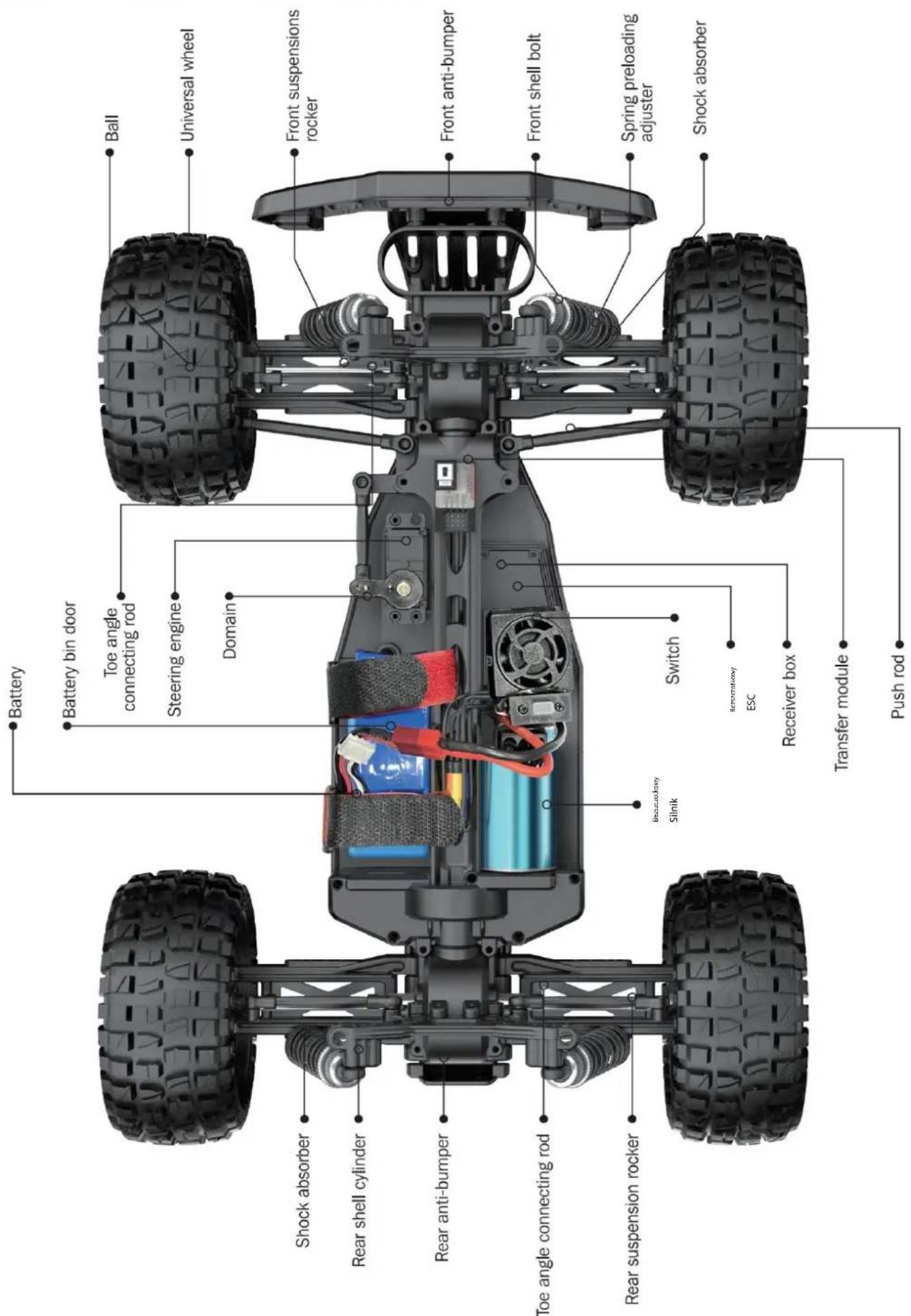
BATTERY INSTALLATION
REMOTE CONTROLLER
Our company has configured a new remote control for the model, Please ready the operation on the instruction manual carefully. Below is the functions description of this remote control.
■ Remote Control 1
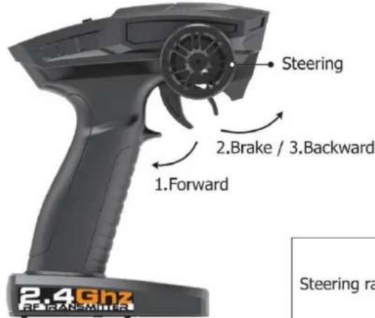
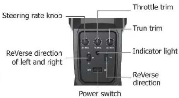
Remote Control 2
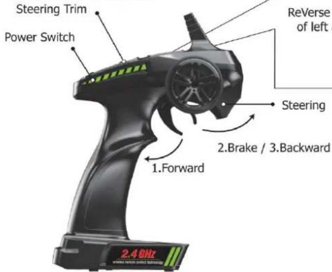
Steering rate knob
Reverse direction of left and right
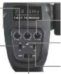
Throttle trim
Trun trim
Indicator light
ReVerse direction
Steering
2.Brake / 3.Backward
2.4GHz
- When the trigger is pulled back, the vehicle advances
- When the vehicle is moving forward, push the trigger forward and the vehicle will brake;
- When the trigger on the remote control returns to the midpoint, push the trigger forward again and the vehicle will retreat.
| LED color/pattern | Name | Hints |
| Red light always on | Normal driving pattern | |
| Red light with slow flash (on at 0.5s/off at 0.5s) | Hint of low power | For more information m please refer to operation of putting new battery into remote on page 6. |
| Red light with quick flash (on at 0.125s/off at 0.125s) | Connect failed/error | If transmitter and receiver are bound unsuccessfully, please close the remote system and restart for recovering normal operation. Please check exceeding scope, low battery or damaged antenna if the connection is failed. |
OPERATION
RC CAR BATTERY
① Take out the clip and open the battery cover.
② Connect the battery outlet to the cable in the battery compartment, then insert the battery to the batter compartment.
③ Close the battery cover and lock it.
If the car will not be used for a long time, make sure to turn it off and remove the battery.
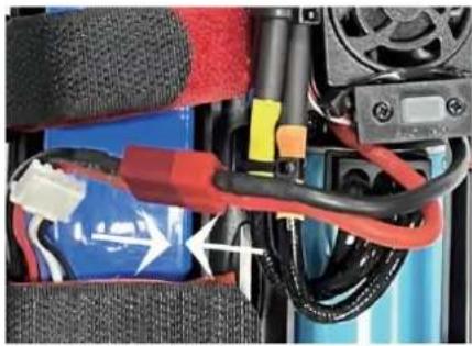
natural_image
Close-up of a battery pack with red and blue wires, no visible text or symbolsREMOTE CONTROL BATTERY
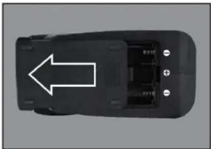
natural_image
Top-down view of a black electronic device casing with a white arrow pointing to its side panel (no text or symbols visible)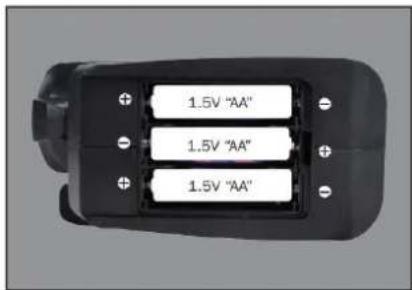
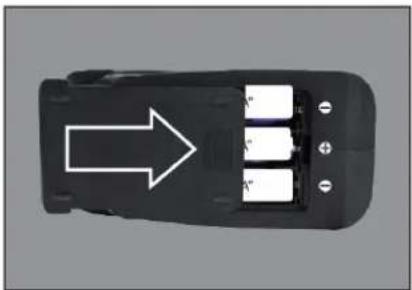
natural_image
Top-down view of a black electronic device with three labeled battery blocks and an arrow pointing to it (no text or symbols on the device itself)① Push the battery cover out.
② Insert 3 AA batteries (not included) in the correct direction.
③ Push the battery cover in.
If the remote will not be used for a long time, make sure to turn it off and remove the batteries.
When the battery of the remote control is low, the indicator light of the remote control will flash slowly.
OPERATION
PAIRING
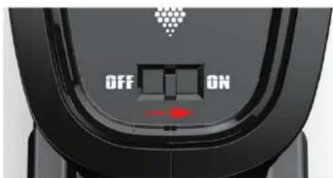
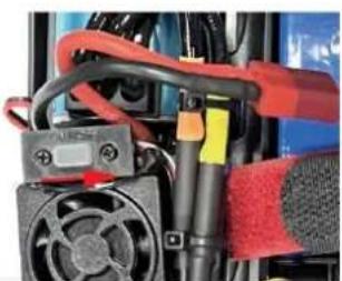
natural_image
Close-up of a mechanical device with red and black components, no visible text or symbols① Make sure the battery is charged.
② Insert batteries to the car and the remote.
③ Turn on the car power switch and the remote power switch. (DO NOT pull the throttle trigger during pairing)
④ Both will automatically pair. (The remote power indicator and the car power indicator will flash while waiting for the pairing process and will turn solid once pairing has been successful)
FREQUENTLY ASKED QUESTIONS
FORWARD, REVERSE, TURN LEFT, TURN RIGHT
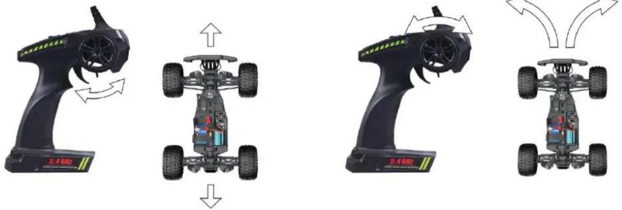
Pull the throttle trigger backward, the car goes forward. Push the throttle trigger forward, the car brakes, then push the throttle trigger forward again, the car goes reverse. (The throttle controls the speed)
Turn the steering control wheel counterclockwise, the car turns left. Turn the steering control wheel clockwise, the car turns right. ( Control the Steering Wheel Rotation Angle can control the degree of turning )
MAXIMUM SPEED CONTROL
Steering Rate Knob
Use the Steering Rate Knob to adjust direction angle when the steering wheel operated.
Increase the steering angle
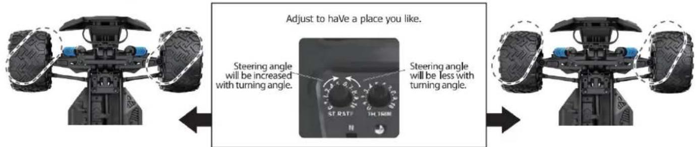
FINE TUNING KNOB OF STEERING
Use throttle to adjust the speed into your ideal one by rotate left or rotate right
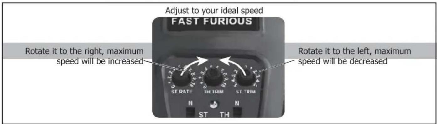
| QUESTION | CAUSE | SOLUTION |
| No match or can't control it | 1. The car battery or remote control battery is completely dead2. Out of remote range | 1. Replace charged battery2. Repair and keep in remote distance |
| Can't go forward or reverse | 1. Low battery2. The car shorted out when it got wet3. Poor contact between motor and electronic regulator | 1. Charging2. Let the car dry completely3. Reconnect the connection wire between the motor and the electronic regulator |
| Can't turn left or turn right | 1. The steering angle knob(ST.RATE) is set to minimum2. Low battery3. The car shorted out when it got wet3. Poor contact between steering gear and electronic regulator | 1. Set the steering angle knob (ST.RATE) to maximum2. Charging3. Let the car dry completely4. Reconnect the connection wire between the steering gear and the electronic regulator |
| It won't charge | 1. The output voltage or current of the power supply is too high2. The charging cable or battery is broken | 1. The output voltage and current of the power supply should be 5V 0.5~2A2. Skontaktuj się z obsługą klienta |
| Something's missing or broken | Skontaktuj się z obsługą klienta | |
| The wheels turn on their own | Pull the throttle trigger during pairing | Repair without pulling the throttle |
SPECIFICATIONS
Motor:
Battery:
Remote frequency:
Remote distance:
Charging mode:
USB balance charging cable
DEVICE EXPLOSION DIAGRAM
9200 ASSEMBLY VIEW
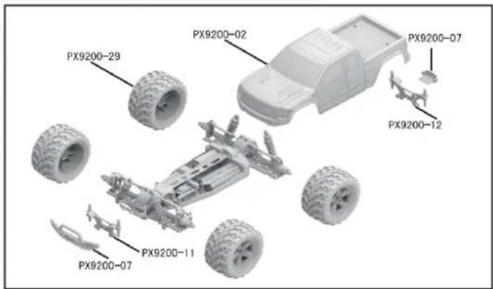
9203 ASSEMBLY VIEW
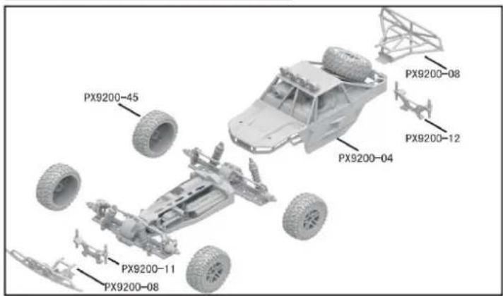
9204 CAR BOBY
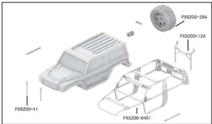
DRIVE AXLE EXPLODED VIEW
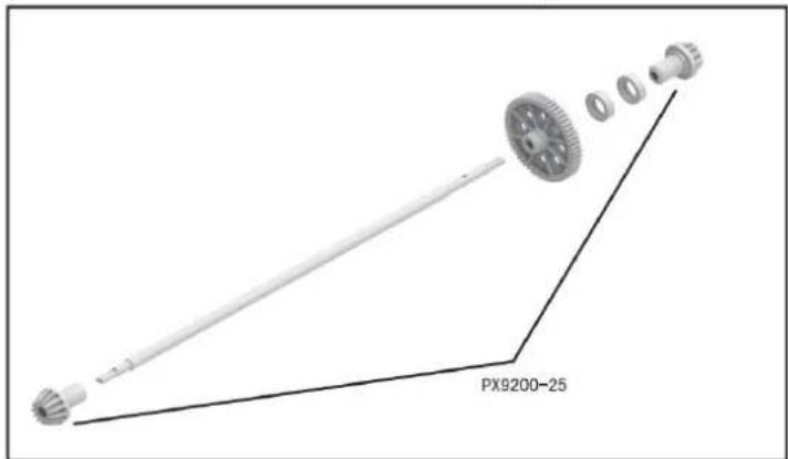
9202 ASSEMBLY VIEW
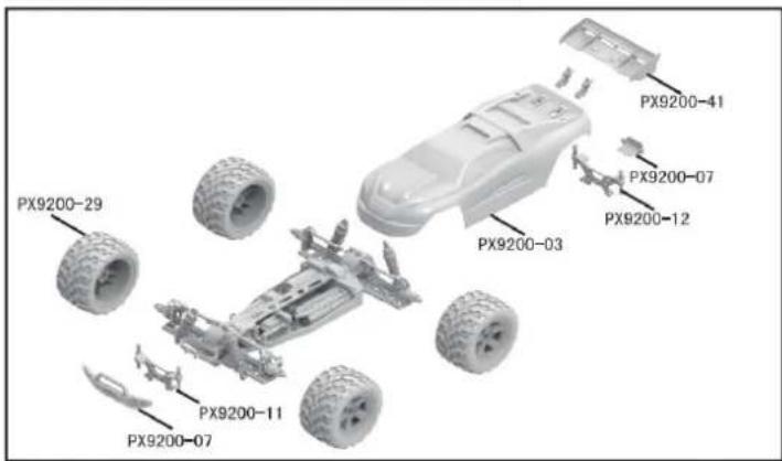
9203 CAR BOBY
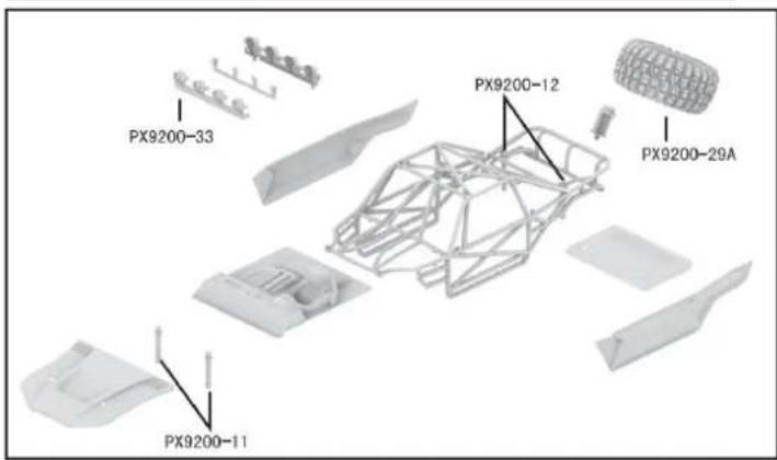
FRONT & REAR DIFFERENTIAL EXPLODED VIEW
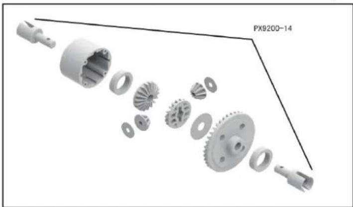
natural_image
Exploded view diagram of a mechanical gear assembly (no text or symbols)TIRE & WHEEL AXLE EXPLODED VIEW
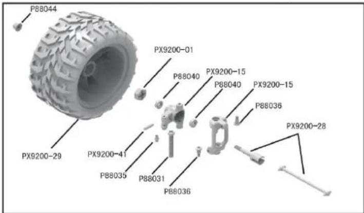
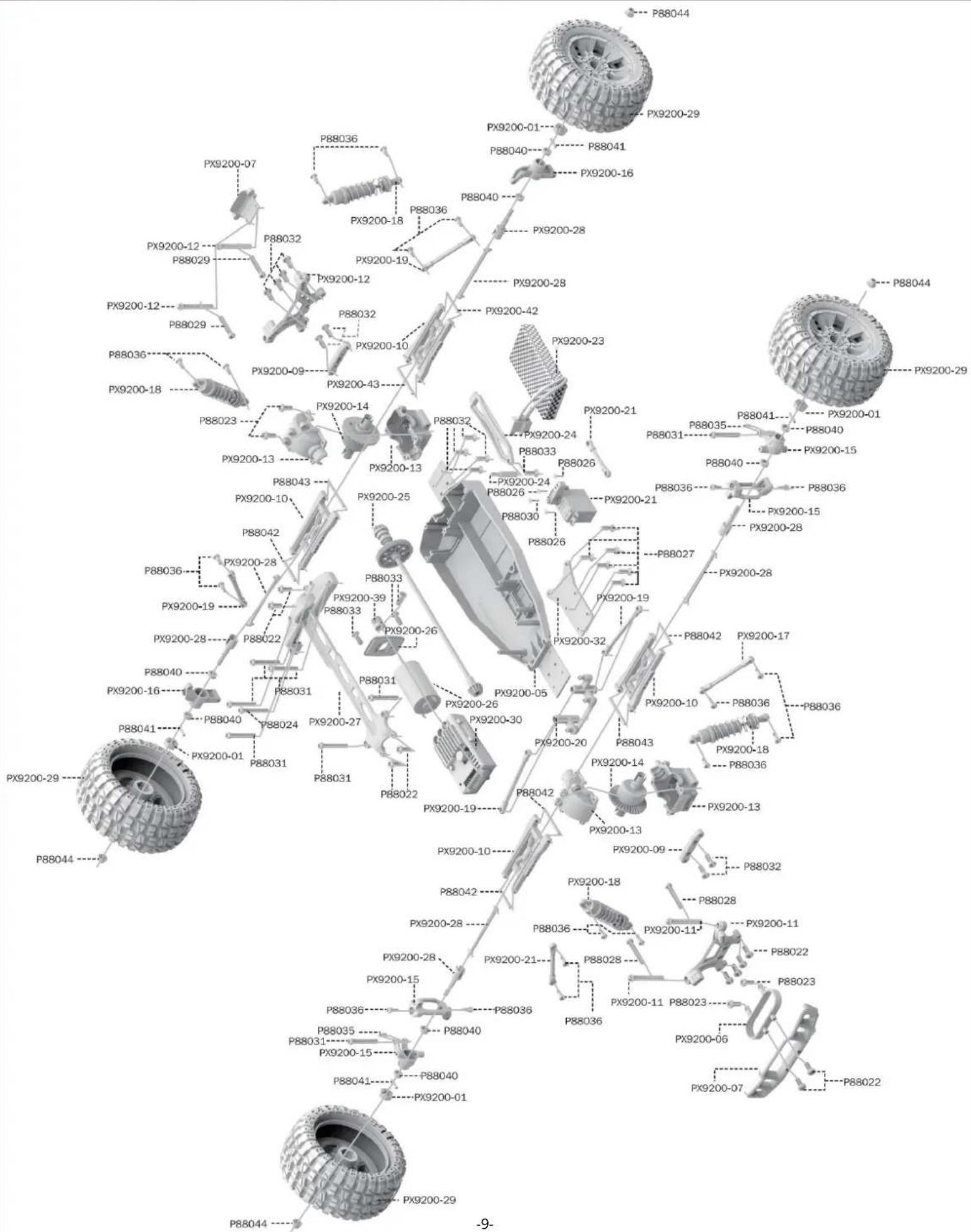
RETAIL ACCESSORY VIEW
PX9200-22
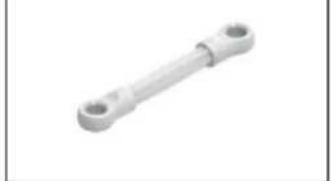
natural_image
Metal mechanical component with two circular ends (no text or symbols visible)Servo Link
PX9200-05
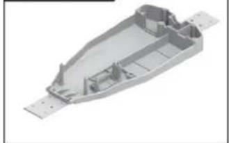
natural_image
3D rendering of a mechanical housing component with visible internal ribs and mounting holes (no text or symbols)Chassis
PX9200-06
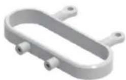
natural_image
3D rendering of a U-shaped mechanical component with two side ports (no text or symbols)Tube-style bumpers
PX9200-07
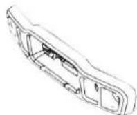
9200-Front/Rear Bumper
PX9200-09
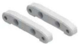
Tie Bar
PX9200-10
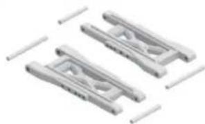
natural_image
Three identical mechanical clamping components with no visible text or symbolsLower Supension Arm
PX9200-11
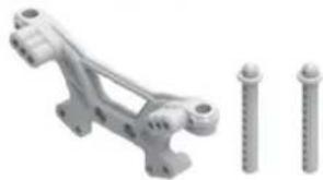
natural_image
Mechanical assembly with two screws and a bracket (no text or symbols visible)Front Shock Tower and Body Post
PX9200-08
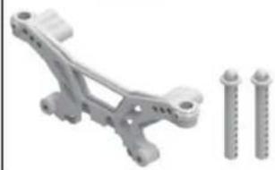
natural_image
Mechanical component with two screws and a bracket, no visible text or symbolsRear Shock Tower and Body Post
PX9200-13
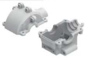
natural_image
Two white plastic mechanical housing components, one open and one closed, with no visible text or markings.Front/Rear Gear Box
PX9200-14
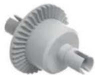
Diff Main Gear Complete
PX9200-15
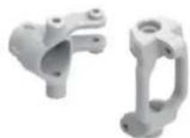
Front Steering Carrier
PX9200-16
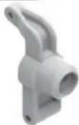
Rear Upright
PX9200-17
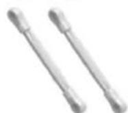
Front/Rear Upper Link
PX9200-18
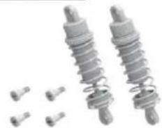
natural_image
Two metallic spring components with bolts and small pins, no text or symbols visibleFront/Rear Shock Absorber
PX9200-19
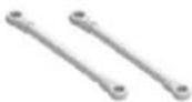
Steering Link
PX9200-20
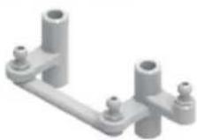
Steering Arm Complete
PX9200-51
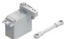
natural_image
3D rendering of a mechanical device with a shaft and housing (no text or symbols visible)Servo
(3 przewody)
RETAIL ACCESSORY VIEW
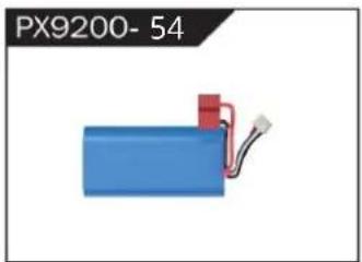
natural_image
Blue battery with red connector and wire, labeled PX9200-54 (no other text or symbols)LIPO Battery (7.4V 4000MAH)
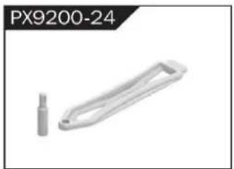
natural_image
Metallic mechanical component with a cylindrical pin and handle, labeled PX9200-24 (no other text or symbols)Battery Cover

natural_image
Mechanical component labeled PX9200-25, showing a shaft with flanged ends and a central hub (no text or symbols on the part itself)Drive Shaft Assembly
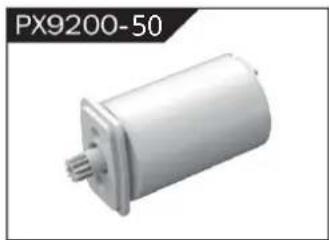
natural_image
Exterior view of a white cylindrical mechanical component (no text or symbols visible)Bezszczotkowy Motor
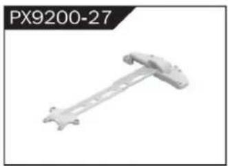
natural_image
Mechanical component labeled PX9200-27, showing a rod-like structure with mounting holes (no text or symbols on the object itself)Motor Layering
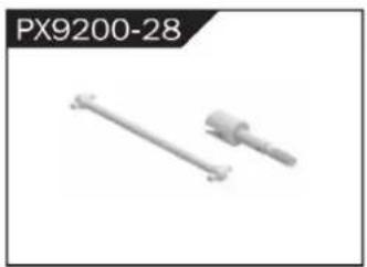
natural_image
Two mechanical components, one straight and one cylindrical, shown without any text or symbols.Universal Drive Joint
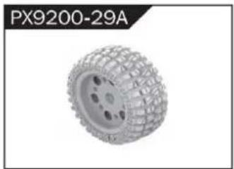
natural_image
3D rendered tire component labeled PX9200-29A, showing textured surface and mounting holes (no text or symbols on the object itself)Vacuum Wheel Complete
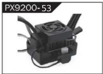
natural_image
Close-up of a black industrial device with cooling fan and cooling fins (no visible text or symbols)ESC
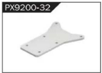
natural_image
3D model of a white plastic mechanical part with mounting holes (no text or symbols visible)Chassis Sheet Steel
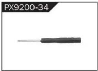
natural_image
Close-up of a black screwdriver with a metallic tip, labeled PX9200-34 (no other text or symbols visible)3MM Crosstip Screwdrivers
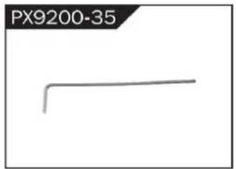
natural_image
Simple line drawing of a bent pipe or rod (no text or symbols)2MM Hexagon Wrench
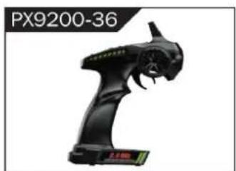
natural_image
Black handheld device labeled PX9200-36, showing a stylized creature with no visible text or symbols on the device itself.I 2.4G Transmitter for all

II 2.4G Transmitter for all
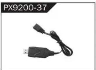
natural_image
Black USB connector with attached cable, labeled PX9200-37 (no other text or symbols visible)7,4 V- USB
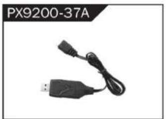
natural_image
Black USB device with attached cable and connector, labeled PX9200-37A (no other text or symbols visible)11,1 V- USB
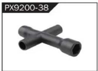
natural_image
Two black X-shaped pipe fittings (no text or symbols visible)Socket Wrench
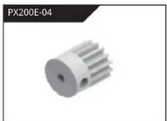
natural_image
3D rendered image of a white mechanical gear or pump component with no visible text or symbolsnatural_image
Metallic heat sink component with radial fins, no visible text or symbolsnatural_image
Group of metallic screw-like components arranged in two rows (no text or symbols visible)Φ2.6*7PB Round Head Screw
natural_image
Group of identical metallic screw-like components arranged in two rows (no text or symbols visible)Φ2.6*10PB Round Head Screw
natural_image
Group of eight identical metallic bolts arranged in two rows (no text or symbols visible)Φ2.6*30PB Round Head Screw
natural_image
Group of metallic screw-like components arranged in two rows (no text or symbols visible)Φ3*12 Round Head Screw
natural_image
Grid of nine identical screw-like components arranged in two rows (no text or symbols visible)Φ2.3*10PB Screw
natural_image
Grid of nine identical screw-like components arranged in two rows (no text or symbols)Φ2.6*12PB Screw
natural_image
Group of metallic bolts arranged in a row (no text or symbols visible)Φ1.7*8PB Screw
natural_image
Row of metallic bolts arranged in two rows (no text or symbols visible)Φ2*8PB Screw
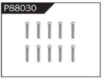
natural_image
Grid of metallic cylindrical pins arranged in three rows (no text or symbols)Φ2.3*14PB Screw
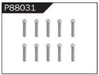
natural_image
Grid of metallic cylindrical pins arranged in three rows (no text or symbols visible)Φ2.6*14PB Screw
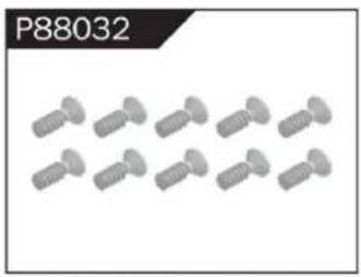
natural_image
Group of identical screwdrivers arranged in two rows (no text or symbols visible)Φ2.6*10 Flattened Head Screw
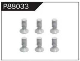
natural_image
Six identical screw-like components arranged in two rows (no text or symbols visible)Φ3*8 Flattened Head Machine Screw
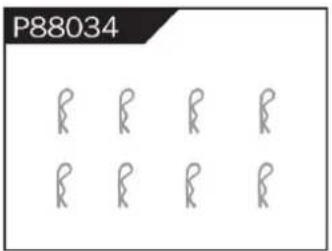
Body Clip

natural_image
Four identical cylindrical mechanical components arranged horizontally (no text or symbols visible)Hollow Ball Connectors
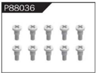
Step Screw
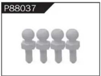
natural_image
Four stylized human figures in a row, no text or symbols presentΦ4.8 Ball Head
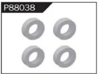
natural_image
Four identical gray ring-shaped objects arranged in a 2x2 grid (no text or symbols)Φ10*15*4 Ball Bearing
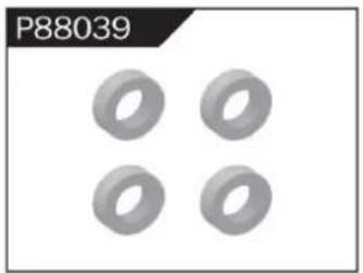
natural_image
Four identical gray ring shapes arranged in a 2x2 grid on a white background (no text or symbols)Φ8*10*3 Ball Bearing
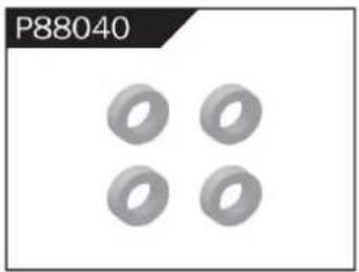
natural_image
Four identical gray ring shapes arranged in a 2x2 grid (no text or symbols)Φ5*9*3 Ball Bearing
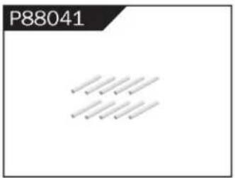
Φ1.5*10 Wheel Hex Pin c
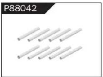
natural_image
Pure diagram of multiple parallel cylindrical rods without any text or symbolsΦ2.5*26.5 Steering Pin B
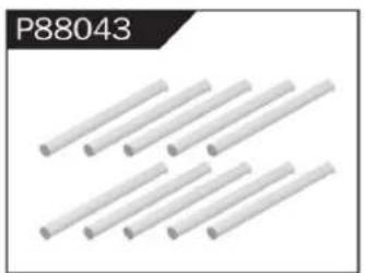
natural_image
Six white cylindrical rods arranged diagonally (no text or symbols visible)Φ3*48 Front/Rear Lower Suspension Pin A
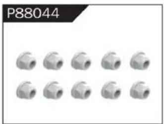
natural_image
Grid of 12 identical mechanical pipe fitting units, no text or symbols visibleNylor Nut M4
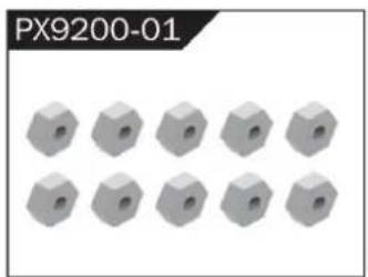
natural_image
12 gray hexagonal nuts arranged in two rows (no text or symbols visible)Wheel Hex
WARNINGS
- According to the instructions provided on the manual. Some part needs to be assembled and adjusted by adults.
- Please use under the guidance of an adult.
- Please promptly put away the packing materials so as not to cause harm to children.
- Do not operate on a location where water is trapped or under the rain. Parts of the product may malfunction if exposed to water.
- Do not touch the rotating wheel to avoid injury.
- The product contains small parts that may pose a risk of ingestion or suffocation.
- To remotely control the product on the road or in a crowd to avoid accidents.
- It is necessary to periodically check the charging USB cable, plug, housing and other components, and immediately unplug if found to be damaged.
- This product can only use the factory configured USB cable to charge the product battery.
- USB cable, battery box, and battery must be inserted into the same specified power supply as the product symbol.
- The USB charging cable and the battery is not a toy.
- Disconnect the rechargeable USB cable before cleaning the toy.
- If you observe electrical charges during product usage, turn off the device immediately.
- When installing or replacing the battery, pay attention to the correct polarity of the battery.
- The remote control car uses a 7.4V Lithium battery.
- It is strictly prohibited do the following actions such as but not limited to disassemble, modify, crash, puncture, drop, throw in a fire or any other means of causing damage to the product to avoid harm to the user and other participants.
- Do not expose the battery to prolonged exposure to sunlight to prevent danger.
- It is advisable to store the battery at a temperature below 30^ C. Do not store it in a place with heat, high temperature, or humidity to avoid danger.
- Non-rechargeable batteries cannot be charged.
- When charging a rechargeable battery, adult supervision is required.
- The rechargeable battery should be removed from the toy before charging.
- Do not mix old and new or different types of batteries.
- Only use the USB cable configured by this product when charging the battery.
- Do not disassemble the battery or modify the battery to avoid risk of fire or explosion.
- After the battery is used, it should be taken out of the remote control car. After cooling the battery, you can then charge it and placed it on a safe location. Unplug the battery outlet from the USB charging cable when not in used and disconnect the power line.
- Stop using the battery as soon as it gives a foul smells or suddenly becomes hot, deformed, discolored, or otherwise abnormal during use or charging.
- After the battery of the remote controller runs out, battery temperature is usually high and would recommend to wait for
30 minutes before charging the battery again. Otherwise, it may damage the battery. - Drained batteries should be removed immediately.
- Do not cause the electrical supply of the wiring port to short circuit.
- If you do not use the product for a long time, remove the batteries of the remote control car and remote control.
- instructions contains important product information, please give time to read for better product experience.
GENERAL INFORMATION
CAN NMB-3 (B)
RF Exposure
Radiation Exposure Statement:
This equipment complies with IC radiation exposure limits set forth for an uncontrolled environment. This equipment should be installed and operated with minimum distance 20cm between the radiator & your body.
BATTERY WARNING:
- Failure to follow all the instructions may result in serious injury, irreparable damage to the battery and may cause a fire, smoke or explosion.
- Always check the battery's condition before charging or using it.
- Replace the battery if damaged, gives a foul odor or show signs of overheating, discoloration, deformation and leakage.
- Never use anything other than the approval charger the battery. Always use a balancing charger for battery. It is recommended that you do not to use any other charger than the one provided with the product.
- The battery temperature must never exceed 60°C (140°F) otherwise the battery could be damaged or ignite.
- Never charge on a flammable surface, near flammable products or inside a vehicle (perferably place the battery in a non-flammable and nonconductive container).
- Never leave the battery unattended during the charging process. Never disassemble or modify the housing's wiring, or puncture the cells. Always ensure that the charger output voltage corresponds to the voltage of the battery. Do not overcharge the batter that may cause short circuit.
- Never expose the battery to moisture or direct sunlight, or store it in a place where temperatures could exceed 60^ C (car in the sun, for example).
- Always keep it out of reach from children.
- Improper battery use may result in a fire, explosion or other hazard.
- Non-rechargeable batteries are not be charge again. Rechargeable batteries are only to be charged with the supervision of an adult.
- Different types of batteries or new or used batteries which are different are not be mixed.
- Batteries are to be inserted with the correct polarity.
- The supply terminal should be used well to avoid short circuit. Examination of the transformer and battery charger regularly is encouraged to check any damage in the cord, plug, enclosure and other parts. If damage is observed, it must not be used until it has been repaired.
- The packaging has to be kept since it contains important information.
- The toy is only to be connected to Class II equipment bearing the symbol.
C/O YH Consulting Limited Biuro 147, Centurion House, London Road,
Staines-upon-Thames, Surrey, TW18 4AX
Importowane do AUS: SIHAO PTY LTD.
1 ROKEVA STREETEASTWOOD NSW 2122 Australia
Importowane do USA: Sanven Technology Ltd.
Apartament 250, 9166 Anaheim Place, Rancho Cucamonga, CA 91730
VEVOR®
TOUGH TOOLS, HALF PRICE
www.vevor.com/support
All Terrain Afstandsbediening Off-Road Truck
MODEL:206E
natural_image
Top-down view of a black and yellow heavy-duty toy car with four large tires, displayed on a concrete floor (no visible text or symbols)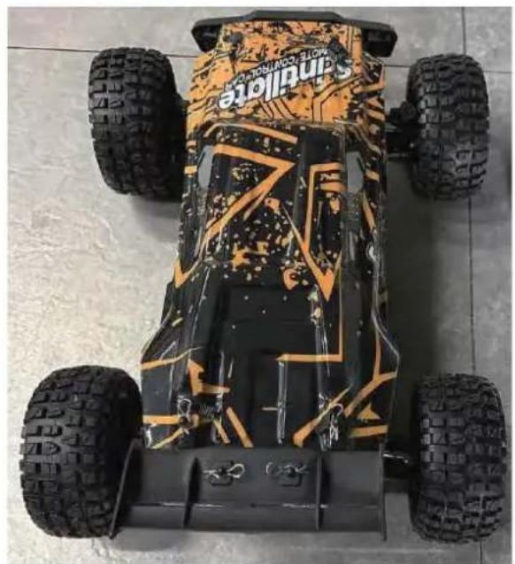
natural_image
Top-down view of a Sandville electric vehicle with four tires and camouflage pattern (no visible text or symbols)206E
HULP NODIG? NEEM CONTACT MET ONS OP!
To make your experience with this remote control car as easy and convenient as possible, please read the instructions provided before using the product. Enjoy and have fun with the product while keeping the manual for future maintenance and reference.
- In order to protect the legitimate rights and interests of users, please be sure to carefully read the contents of this manual before using this product.
- When using this product, please be sure to strictly observe and perform the requirements which includes but not limited to the instructions and safety guidelines. For any personal injury, accident, property loss, legal dispute, or any other adverse event causing a conflict of interest resulting from the use of the product or any irresistible factors that are in violation of the safety instructions, the user shall bear the related responsibilities and losses.
- Once you start using the product, you are deemed to have read, understood, recommended, and accepted all terms and contents of the instructions (including disclaimers, safety instructions, warning instructions, etc.) included with this product.
- In case you are having challenges on any aspect of the product, may it be operation or maintenance, please contact your local sales agent
PACKAGE CONTENTS
| | | | | |
| RC Car | Remote Control | 7,4V USB-poort | 7,4V LI-PO | Product Manual | Accessory package |
CHARGING
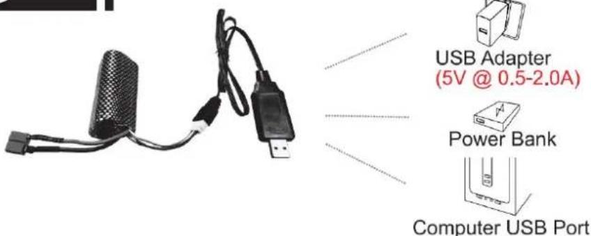
The battery isn't fully charged when it's made. When the car battery low, the car will start the LVC (Low Voltage Cutoff) protection function to protect the battery, the car can only turn, not forward and backward. Please charge the battery.
- Plug the USB charging cable into the USB charging port of the computer, power bank or USB adapter (5V@0.5\~2.0A).
- Connect the battery wire to the USB charging cable.
- Charging time: about 250 minutes.
- The green indicator light on the USB charging cable will flash when it is charging and will turn stevig once fully charged.
ATTENTION:
- Please keep the battery in sight when charging. DO NOT put the battery on a flammable surface.
- If battery pack and USB charging cable are damaged, immediately stop using it and replace the accessories as soon as possible.
RC CAR'S DETAILS
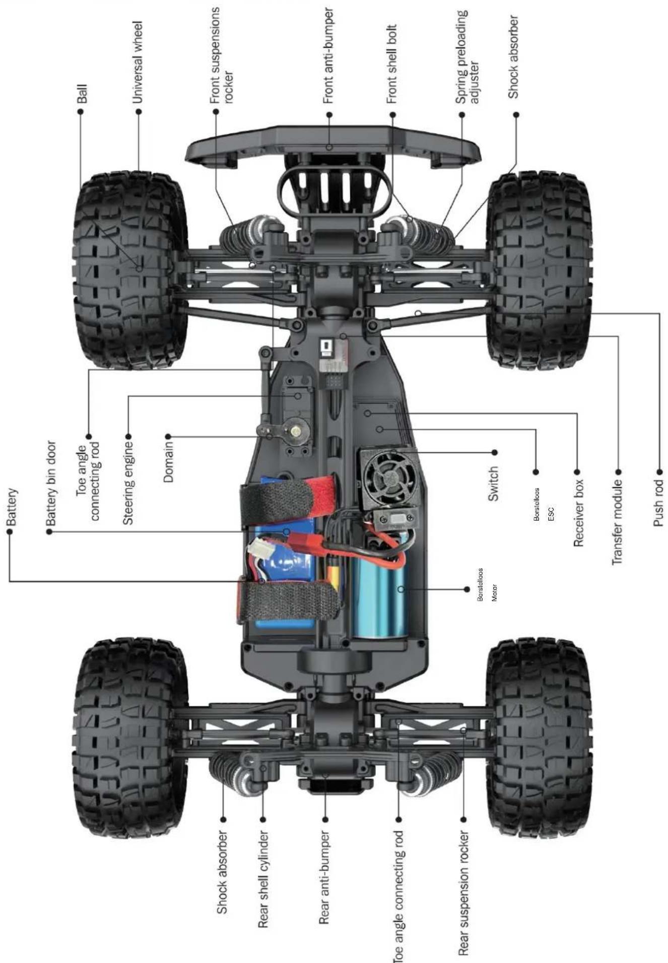
BATTERY INSTALLATION
REMOTE CONTROLLER
Our company has configured a new remote control for the model, Please ready the operation on the instruction manual carefully. Below is the functions description of this remote control.
■ Remote Control 1
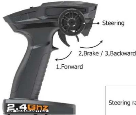
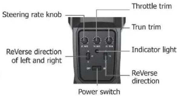
Remote Control 2
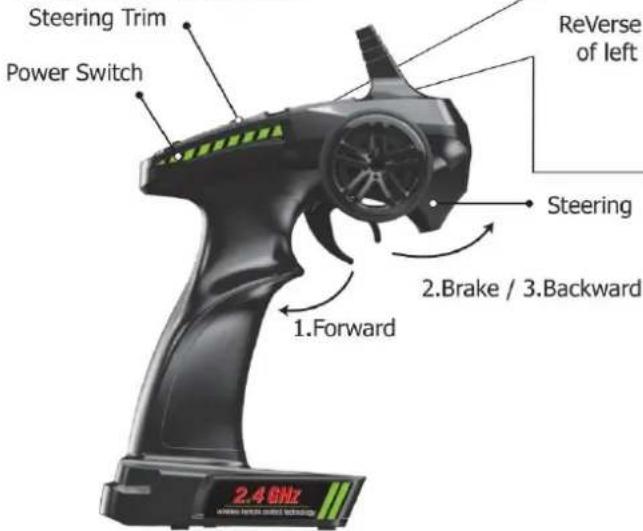
Steering rate knob
Reverse direction of left and right
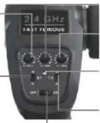
Throttle trim
Trun trim
Indicator light
ReVerse direction
Steering
2.Brake / 3.Backward
2.4GHz
- When the trigger is pulled back, the vehicle advances
- When the vehicle is moving forward, push the trigger forward and the vehicle will brake;
- When the trigger on the remote control returns to the midpoint, push the trigger forward again and the vehicle will retreat.
| LED color/pattern | Name | Hints |
| Red light always on | Normal driving pattern | |
| Red light with slow flash (on at 0.5s/off at 0.5s) | Hint of low power | For more information m please refer to operation of putting new battery into remote on page 6. |
| Red light with quick flash (on at 0.125s/off at 0.125s) | Connect failed/error | If transmitter and receiver are bound unsuccessfully, please close the remote system and restart for recovering normal operation. Please check exceeding scope, low battery or damaged antenna if the connection is failed. |
OPERATION
RC CAR BATTERY
① Take out the clip and open the battery cover.
② Connect the battery outlet to the cable in the battery compartment, then insert the battery to the batter compartment.
③ Close the battery cover and lock it.
If the car will not be used for a long time, make sure to turn it off and remove the battery.
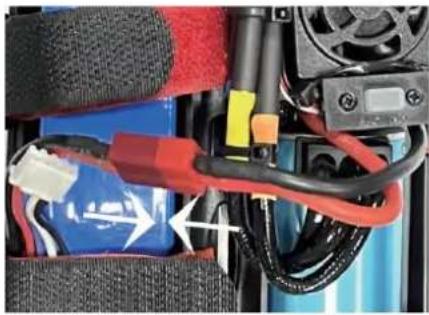
natural_image
Close-up of a battery pack with red and blue wires, no visible text or symbolsREMOTE CONTROL BATTERY
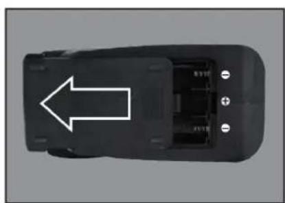
natural_image
Top-down view of a black car component with a white arrow pointing to the side (no text or symbols visible)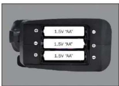
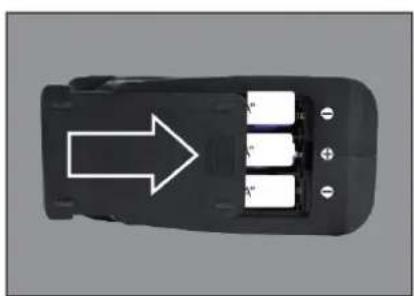
natural_image
Top-down view of a black car interior with three battery cells and an arrow pointing to one (no text or symbols)① Push the battery cover out.
② Insert 3 AA batteries (not included) in the correct direction.
③ Push the battery cover in.
If the remote will not be used for a long time, make sure to turn it off and remove the batteries.
When the battery of the remote control is low, the indicator light of the remote control will flash slowly.
OPERATION
PAIRING
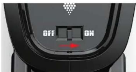
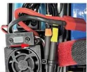
natural_image
Close-up of a mechanical assembly with red and black components, no visible text or symbols① Make sure the battery is charged.
② Insert batteries to the car and the remote.
③ Turn on the car power switch and the remote power switch. (DO NOT pull the throttle trigger during pairing)
④ Both will automatically pair. (The remote power indicator and the car power indicator will flash while waiting for the pairing process and will turn solid once pairing has been successful)
FREQUENTLY ASKED QUESTIONS
FORWARD, REVERSE, TURN LEFT, TURN RIGHT
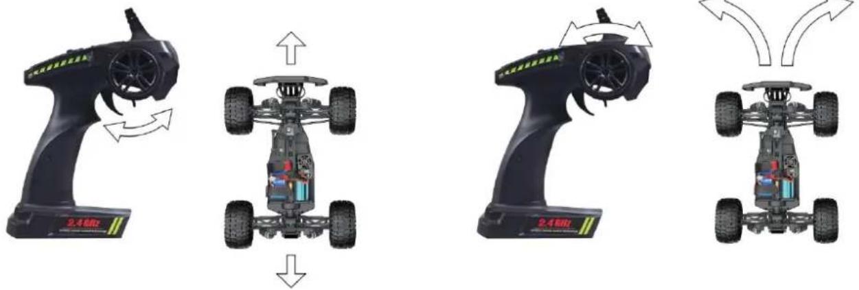
Pull the throttle trigger backward, the car goes forward. Push the throttle trigger forward, the car brakes, then push the throttle trigger forward again, the car goes reverse. (The throttle controls the speed)
Turn the steering control wheel counterclockwise, the car turns left. Turn the steering control wheel clockwise, the car turns right. ( Control the Steering Wheel Rotation Angle can control the degree of turning )
MAXIMUM SPEED CONTROL
Steering Rate Knob
Use the Steering Rate Knob to adjust direction angle when the steering wheel operated.
Increase the steering angle
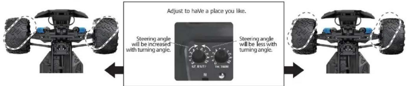
FINE TUNING KNOB OF STEERING
Use throttle to adjust the speed into your ideal one by rotate left or rotate right
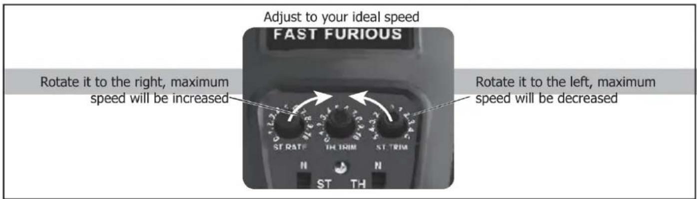
| QUESTION | CAUSE | SOLUTION |
| No match or can't control it | 1. The car battery or remote control battery is completely dead2. Out of remote range | 1. Replace charged battery2. Repair and keep in remote distance |
| Can't go forward or reverse | 1. Low battery2. The car shorted out when it got wet3. Poor contact between motor and electronic regulator | 1. Charging2. Let the car dry completely3. Reconnect the connection wire between the motor and the electronic regulator |
| Can't turn left or turn right | 1. The steering angle knob(ST.RATE) is set to minimum2. Low battery3. The car shorted out when it got wet3. Poor contact between steering gear and electronic regulator | 1. Set the steering angle knob (ST.RATE) to maximum2. Charging3. Let the car dry completely4. Reconnect the connection wire between the steering gear and the electronic regulator |
| It won't charge | 1. The output voltage or current of the power supply is too high2. The charging cable or battery is broken | 1. The output voltage and current of the power supply should be 5V0.5~2A2. Neem contact op met de klantenservice |
| Something's missing or broken | Neem contact op met de klantenservice | |
| The wheels turn on their own | Pull the throttle trigger during pairing | Repair without pulling the throttle |
SPECIFICATIONS
Motor:
Battery:
Remote frequency:
Remote distance:
Charging mode:
Borstelloze motor
7,4V lithium battery
2.4GHz
100m
USB balance charging cable
DEVICE EXPLOSION DIAGRAM
9200 ASSEMBLY VIEW
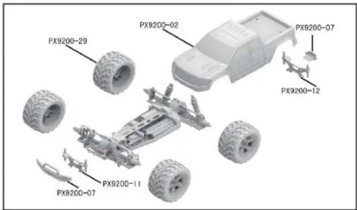
9203 ASSEMBLY VIEW
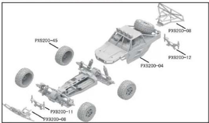
9204 CAR BOBY
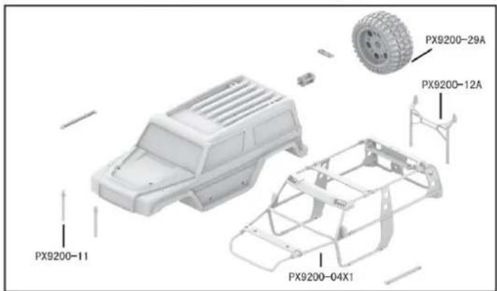
DRIVE AXLE EXPLODED VIEW
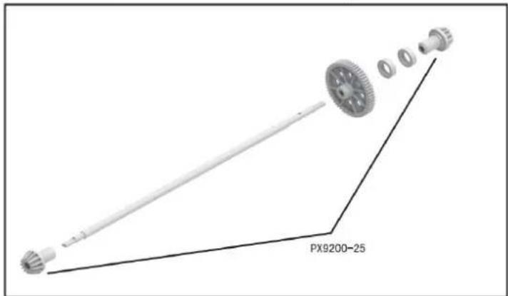
9202 ASSEMBLY VIEW

9203 CAR BOBY

FRONT & REAR DIFFERENTIAL EXPLODED VIEW
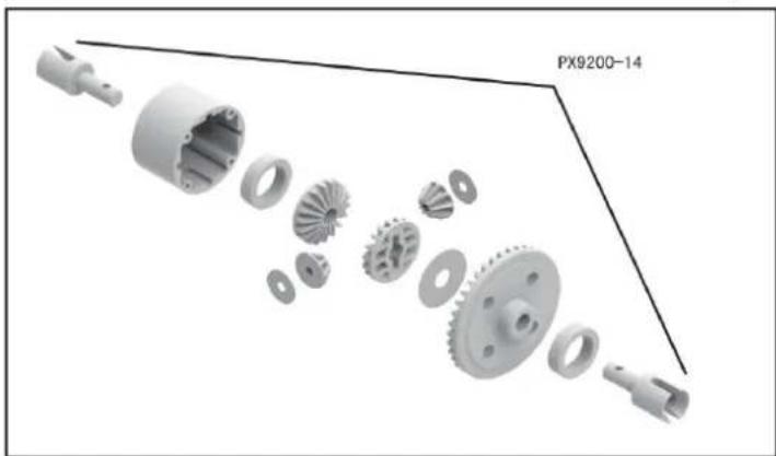
natural_image
Exploded view diagram of a mechanical gear assembly (no text or symbols)TIRE & WHEEL AXLE EXPLODED VIEW
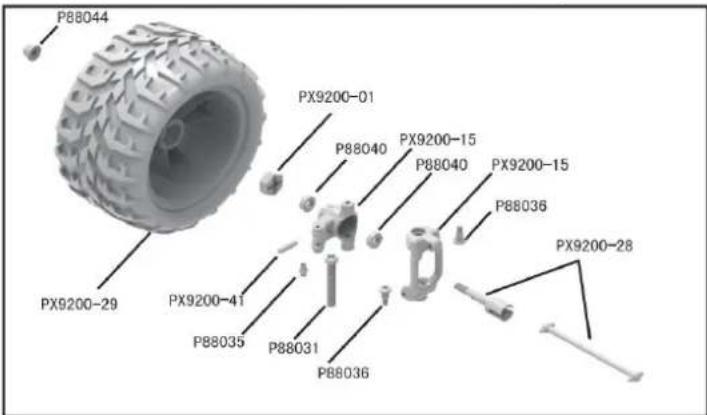
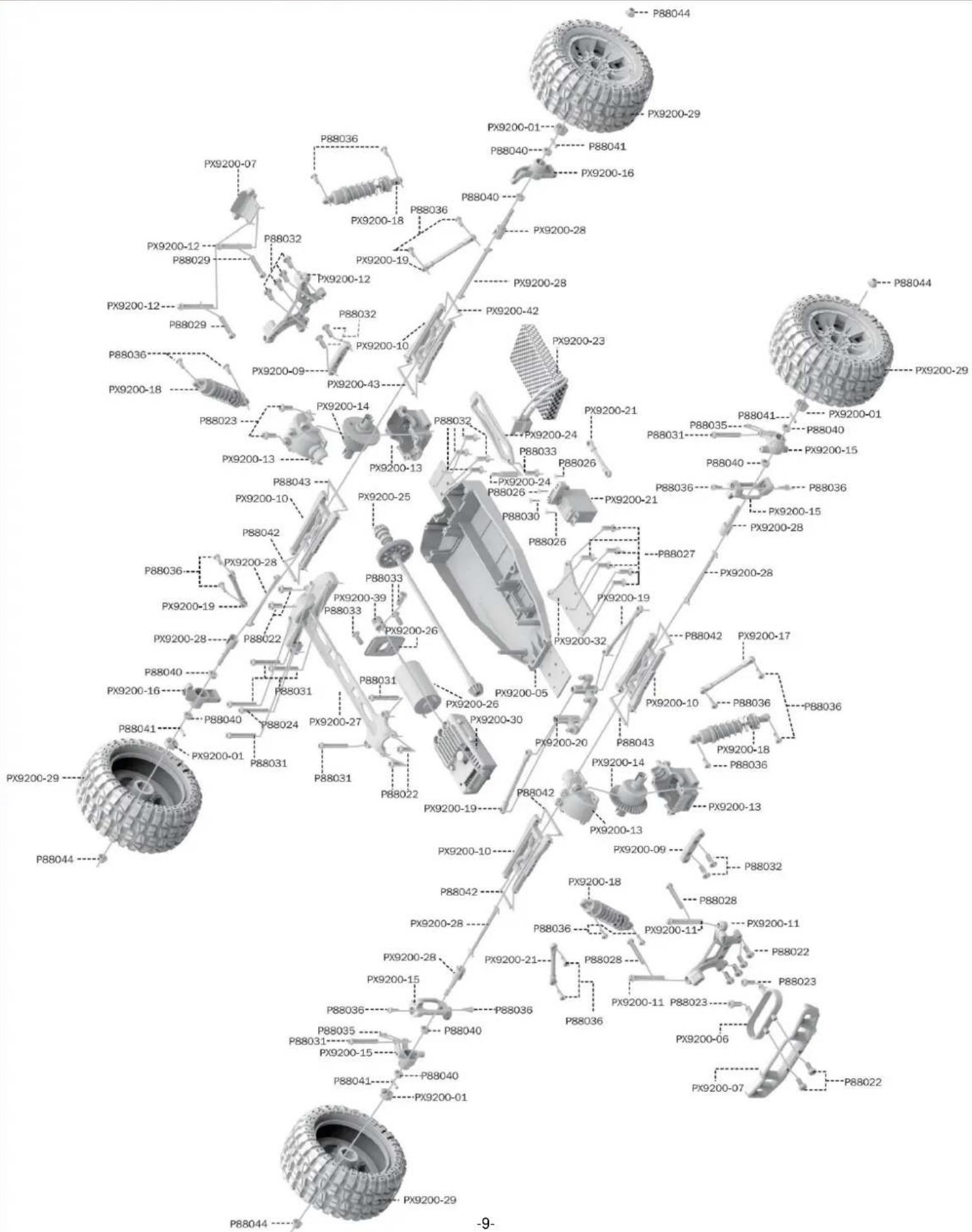
RETAIL ACCESSORY VIEW
PX9200-22
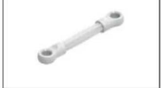
natural_image
Metal mechanical component with two circular ends (no text or symbols visible)Servo Link
PX9200-05
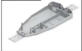
natural_image
3D rendering of a mechanical housing component with visible internal ribs and mounting holes (no text or symbols)Chassis
PX9200-06
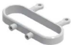
natural_image
3D rendering of a U-shaped mechanical component with two side ports (no text or symbols)Tube-style bumpers
PX9200-07
9200-Front/Rear Bumper
PX9200-09
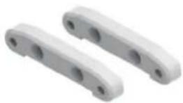
Tie Bar
PX9200-10
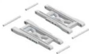
natural_image
Three identical mechanical clamping components with no visible text or symbolsLower Supension Arm
PX9200-11
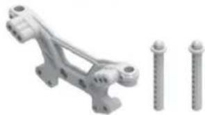
natural_image
Mechanical assembly with two screws and a bracket (no text or symbols visible)Front Shock Tower and Body Post
PX9200-08
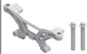
natural_image
Mechanical component with two screws and a bracket, no visible text or symbolsRear Shock Tower and Body Post
PX9200-13
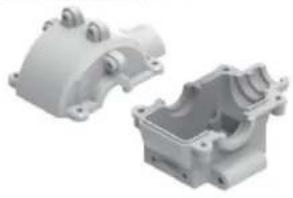
natural_image
Two white plastic mechanical parts, one open and one closed, with no visible text or symbols.Front/Rear Gear Box
PX9200-14

Diff Main Gear Complete
PX9200-15
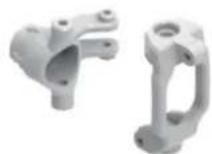
Front Steering Carrier
PX9200-16
Rear Upright
PX9200-17
Front/Rear Upper Link
PX9200-18
natural_image
Two metallic spring components with bolts and small pins, no text or symbols visibleFront/Rear Shock Absorber
PX9200-19
Steering Link
PX9200-20
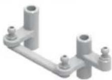
Steering Arm Complete
PX9200-51
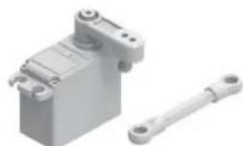
natural_image
3D rendering of a mechanical device with a shaft and housing (no text or symbols visible)Servo (3 draden)
RETAIL ACCESSORY VIEW
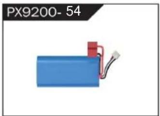
natural_image
Blue battery with red connector and wire, labeled PX9200-54 (no other text or symbols)LIPO Battery (7.4V 4000MAH)
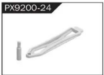
natural_image
Metallic mechanical component with a cylindrical pin and handle, labeled PX9200-24 (no other text or symbols)Battery Cover
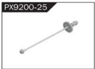
natural_image
Mechanical component labeled PX9200-25, showing a shaft with flanged ends and a central hub (no text or symbols on the part itself)Drive Shaft Assembly
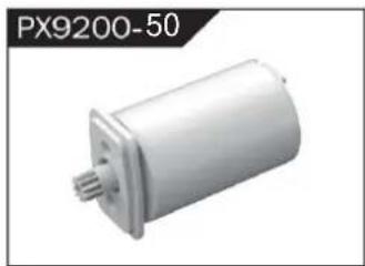
natural_image
Exterior view of a white cylindrical mechanical component (no text or symbols visible)Borstelloos Motor
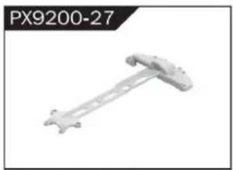
natural_image
Mechanical component labeled PX9200-27, showing a rod-like structure with mounting holes (no text or symbols on the part itself)Motor Layering
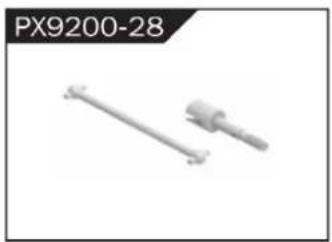
natural_image
Two mechanical components, one straight and one cylindrical, shown without any text or symbols.Universal Drive Joint
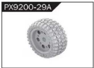
natural_image
3D rendered tire component labeled PX9200-29A, showing textured surface and mounting holes (no text or symbols on the object itself)Vacuum Wheel Complete
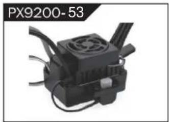
natural_image
Close-up of a black industrial device with cooling fan and cooling fins (no visible text or symbols)ESC
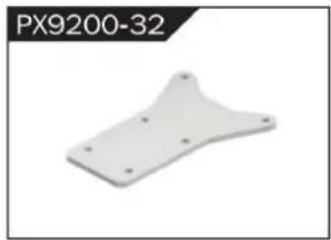
natural_image
White plastic mechanical part with mounting holes, labeled PX9200-32 (no other text or symbols)Chassis Sheet Steel
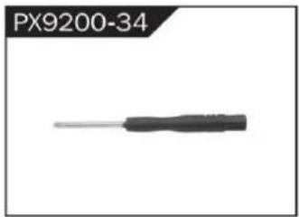
natural_image
Close-up of a black screwdriver with a metallic tip, labeled PX9200-34 (no other text or symbols visible)3MM Crosstip Screwdrivers
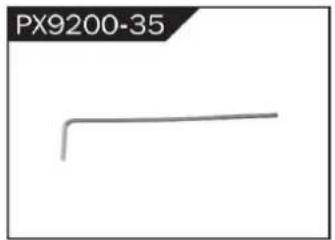
natural_image
Simple line drawing of a bent pipe or rod (no text or symbols)2MM Hexagon Wrench
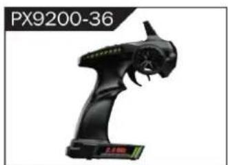
natural_image
Black handheld device labeled PX9200-36, showing a stylized creature with no visible text or symbols on the device itself.I 2.4G Transmitter for all

II 2.4G Transmitter for all
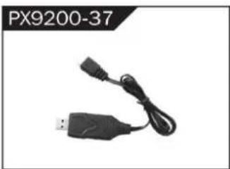
natural_image
Black USB connector with attached cable, labeled PX9200-37 (no other text or symbols visible)7.4V- USB
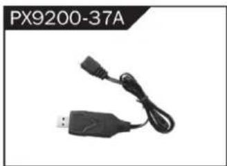
natural_image
Black USB plug with attached cable, labeled PX9200-37A (no other text or symbols visible)11.1V- USB
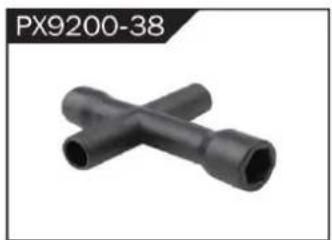
natural_image
Two black X-shaped pipe fittings (no text or symbols visible)Socket Wrench
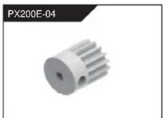
natural_image
3D rendered image of a white mechanical gear or pump component with no visible text or symbolsMotorversnelling (17t)
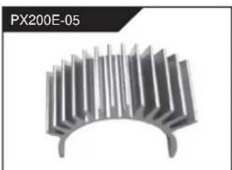
natural_image
Metallic heat sink component with radial fins, no visible text or symbolsnatural_image
Group of metallic screw-like components arranged in two rows (no text or symbols visible)Φ2.6*7PB Round Head Screw
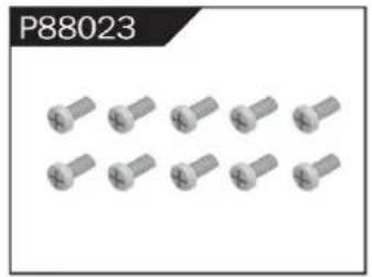
natural_image
Group of identical metallic screw-like components arranged in two rows (no text or symbols visible)Φ2.6*10PB Round Head Screw
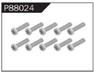
natural_image
Group of eight identical metallic bolts arranged in two rows (no text or symbols visible)Φ2.6*30PB Round Head Screw
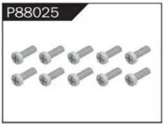
natural_image
Group of metallic screw-like components arranged in two rows (no text or symbols visible)Φ3*12 Round Head Screw
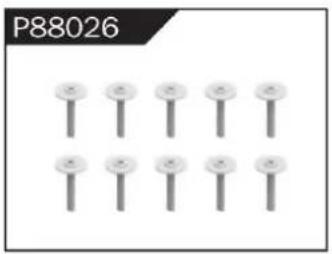
natural_image
Grid of nine identical screw-like components arranged in two rows (no text or symbols visible)Φ2.3*10PB Screw
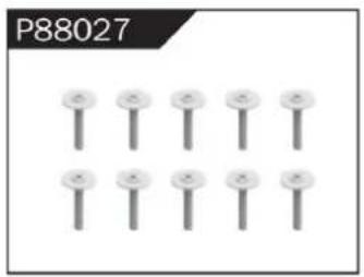
natural_image
Grid of nine identical screw-like components arranged in two rows (no text or symbols visible)Φ2.6*12PB Screw
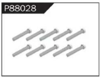
natural_image
Group of metallic bolts arranged in a row (no text or symbols visible)Φ1.7*8PB Screw
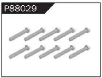
natural_image
Row of metallic bolts arranged in two rows (no text or symbols visible)Φ2*8PB Screw
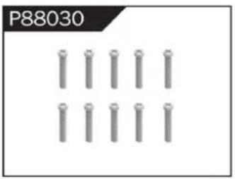
natural_image
Grid of metallic cylindrical pins arranged in three rows (no text or symbols)Φ2.3*14PB Screw
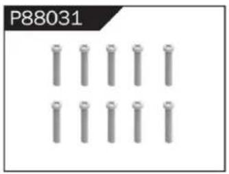
natural_image
Grid of metallic cylindrical pins arranged in three rows (no text or symbols visible)Φ2.6*14PB Screw
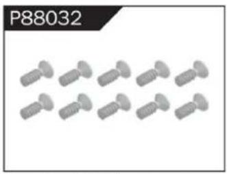
natural_image
Group of identical screwdrivers arranged in two rows (no text or symbols visible)Φ2.6*10 Flattened Head Screw
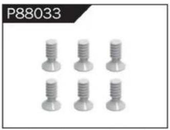
natural_image
Six identical screw-like components arranged in two rows (no text or symbols visible)Φ3*8 Flattened Head Machine Screw
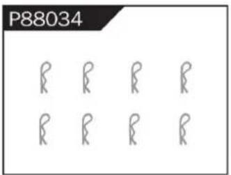
Body Clip
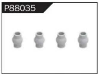
natural_image
Four identical cylindrical mechanical components arranged horizontally (no text or symbols visible)Hollow Ball Connectors
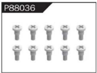
Step Screw
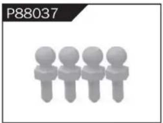
natural_image
Four stylized human figures in a row, no text or symbols presentΦ4.8 Ball Head
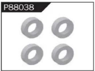
natural_image
Four identical gray ring-shaped objects arranged in a 2x2 grid (no text or symbols)Φ10*15*4 Ball Bearing
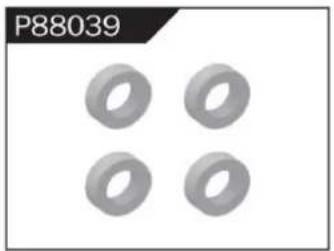
natural_image
Four identical gray ring shapes arranged in a 2x2 grid on a white background (no text or symbols)Φ8*10*3 Ball Bearing
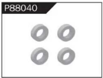
natural_image
Four identical gray ring shapes arranged in a 2x2 grid (no text or symbols)Φ5*9*3 Ball Bearing
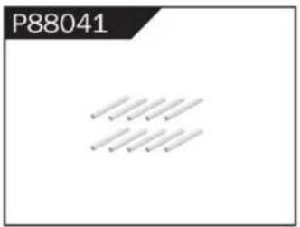
Φ1.5*10 Wheel Hex Pin c
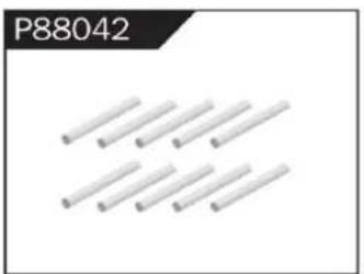
natural_image
Pure diagram of multiple parallel cylindrical rods without any text or symbolsΦ2.5*26.5 Steering Pin B
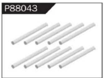
natural_image
Close-up of white cylindrical rods arranged in a diagonal pattern (no text or symbols visible)Φ3*48 Front/Rear Lower Suspension Pin A
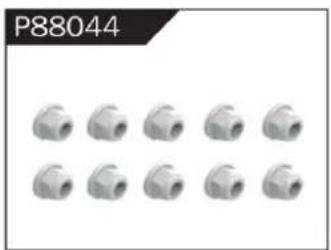
natural_image
Grid of 12 identical mechanical pipe fitting units (no text or symbols visible)Nylor Nut M4
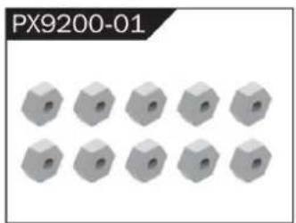
natural_image
12 gray hexagonal nuts arranged in two rows (no text or symbols visible)Wheel Hex
WARNINGS
- According to the instructions provided on the manual. Some part needs to be assembled and adjusted by adults.
- Please use under the guidance of an adult.
- Please promptly put away the packing materials so as not to cause harm to children.
- Do not operate on a location where water is trapped or under the rain. Parts of the product may malfunction if exposed to water.
- Do not touch the rotating wheel to avoid injury.
- The product contains small parts that may pose a risk of ingestion or suffocation.
- To remotely control the product on the road or in a crowd to avoid accidents.
- It is necessary to periodically check the charging USB cable, plug, housing and other components, and immediately unplug if found to be damaged.
- This product can only use the factory configured USB cable to charge the product battery.
- USB cable, battery box, and battery must be inserted into the same specified power supply as the product symbol.
- The USB charging cable and the battery is not a toy.
- Disconnect the rechargeable USB cable before cleaning the toy.
- If you observe electrical charges during product usage, turn off the device immediately.
- When installing or replacing the battery, pay attention to the correct polarity of the battery.
- The remote control car uses a 7.4V Lithium battery.
- It is strictly prohibited do the following actions such as but not limited to disassemble, modify, crash, puncture, drop, throw in a fire or any other means of causing damage to the product to avoid harm to the user and other participants.
- Do not expose the battery to prolonged exposure to sunlight to prevent danger.
- It is advisable to store the battery at a temperature below 30^ C. Do not store it in a place with heat, high temperature, or humidity to avoid danger.
- Non-rechargeable batteries cannot be charged.
- When charging a rechargeable battery, adult supervision is required.
- The rechargeable battery should be removed from the toy before charging.
- Do not mix old and new or different types of batteries.
- Only use the USB cable configured by this product when charging the battery.
- Do not disassemble the battery or modify the battery to avoid risk of fire or explosion.
- After the battery is used, it should be taken out of the remote control car. After cooling the battery, you can then charge it and placed it on a safe location. Unplug the battery outlet from the USB charging cable when not in used and disconnect the power line.
- Stop using the battery as soon as it gives a foul smells or suddenly becomes hot, deformed, discolored, or otherwise abnormal during use or charging.
- After the battery of the remote controller runs out, battery temperature is usually high and would recommend to wait for
30 minutes before charging the battery again. Otherwise, it may damage the battery. - Drained batteries should be removed immediately.
- Do not cause the electrical supply of the wiring port to short circuit.
- If you do not use the product for a long time, remove the batteries of the remote control car and remote control.
- instructions contains important product information, please give time to read for better product experience.
GENERAL INFORMATION
CAN NMB-3 (B)
RF Exposure
Radiation Exposure Statement:
This equipment complies with IC radiation exposure limits set forth for an uncontrolled environment. This equipment should be installed and operated with minimum distance 20cm between the radiator & your body.
BATTERY WARNING:
- Failure to follow all the instructions may result in serious injury, irreparable damage to the battery and may cause a fire, smoke or explosion.
- Always check the battery's condition before charging or using it.
- Replace the battery if damaged, gives a foul odor or show signs of overheating, discoloration, deformation and leakage.
- Never use anything other than the approval charger the battery. Always use a balancing charger for battery. It is recommended that you do not to use any other charger than the one provided with the product.
- The battery temperature must never exceed 60°C (140°F) otherwise the battery could be damaged or ignite.
- Never charge on a flammable surface, near flammable products or inside a vehicle (perferably place the battery in a non-flammable and nonconductive container).
- Never leave the battery unattended during the charging process. Never disassemble or modify the housing's wiring, or puncture the cells. Always ensure that the charger output voltage corresponds to the voltage of the battery. Do not overcharge the batter that may cause short circuit.
- Never expose the battery to moisture or direct sunlight, or store it in a place where temperatures could exceed 60^ C (car in the sun, for example).
- Always keep it out of reach from children.
- Improper battery use may result in a fire, explosion or other hazard.
- Non-rechargeable batteries are not be charge again. Rechargeable batteries are only to be charged with the supervision of an adult.
- Different types of batteries or new or used batteries which are different are not be mixed.
- Batteries are to be inserted with the correct polarity.
- The supply terminal should be used well to avoid short circuit. Examination of the transformer and battery charger regularly is encouraged to check any damage in the cord, plug, enclosure and other parts. If damage is observed, it must not be used until it has been repaired.
- The packaging has to be kept since it contains important information.
- The toy is only to be connected to Class II equipment bearing the symbol.
All Terrain Afstandsbediening Off-Road Truck
FCC-informatie (FCC-(ID: 2AMOZ9300E19880224): )
C/O YH Consulting Limited Kantoor 147, Centurion House, London Road, Staines-upon-Thames, Surrey, TW18 4AX
Suite 250, 9166 Anaheim Place, Rancho Cucamonga, CA 91730
VEVOR®
TOUGH TOOLS, HALF PRICE
garantiecertificaat www.vevor.com/support
VEVOR®
TOUGH TOOLS, HALF PRICE
www.vevor.com/support
natural_image
Top-down view of a black and yellow heavy-duty toy car with four large tires, parked on a concrete floor (no visible text or symbols)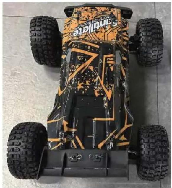
natural_image
Top-down view of a Sandville electric vehicle with four tires and camouflage pattern (no visible text or symbols)206E
BEHÖVER HJÄLP? KONTAKTA OSS!
To make your experience with this remote control car as easy and convenient as possible, please read the instructions provided before using the product. Enjoy and have fun with the product while keeping the manual for future maintenance and reference.
- In order to protect the legitimate rights and interests of users, please be sure to carefully read the contents of this manual before using this product.
- When using this product, please be sure to strictly observe and perform the requirements which includes but not limited to the instructions and safety guidelines. For any personal injury, accident, property loss, legal dispute, or any other adverse event causing a conflict of interest resulting from the use of the product or any irresistible factors that are in violation of the safety instructions, the user shall bear the related responsibilities and losses.
- Once you start using the product, you are deemed to have read, understood, recommended, and accepted all terms and contents of the instructions (including disclaimers, safety instructions, warning instructions, etc.) included with this product.
- In case you are having challenges on any aspect of the product, may it be operation or maintenance, please contact your local sales agent
PACKAGE CONTENTS
| | | | | |
| RC Car | Remote Control | 7,4V USB | 7,4V LI-PO | Product Manual | Accessory package |
CHARGING
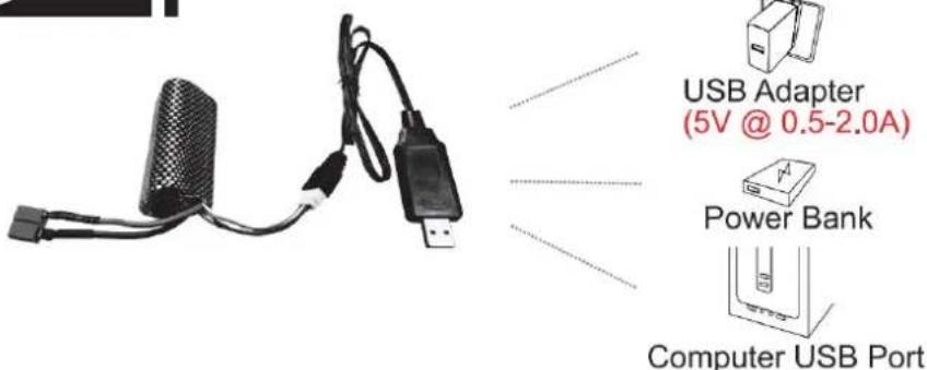
The battery isn't fully charged when it's made. When the car battery low, the car will start the LVC (Low Voltage Cutoff) protection function to protect the battery, the car can only turn, not forward and backward. Please charge the battery.
- Plug the USB charging cable into the USB charging port of the computer, power bank or USB adapter (5V@0.5\~2.0A).
- Connect the battery wire to the USB charging cable.
- Charging time: about 250 minutes.
- The green indicator light on the USB charging cable will flash when it is charging and will turn fast once fully charged.
ATTENTION:
- Please keep the battery in sight when charging. DO NOT put the battery on a flammable surface.
- If battery pack and USB charging cable are damaged, immediately stop using it and replace the accessories as soon as possible.
RC CAR'S DETAILS
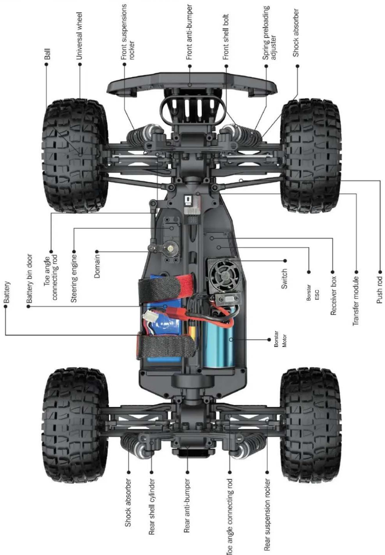
BATTERY INSTALLATION
REMOTE CONTROLLER
Our company has configured a new remote control for the model, Please ready the operation on the instruction manual carefully. Below is the functions description of this remote control.
■ Remote Control 1
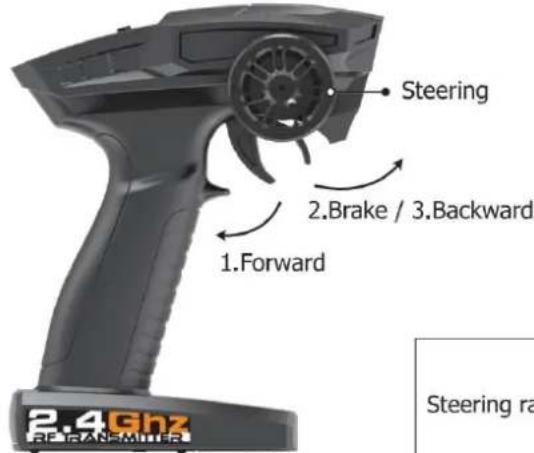
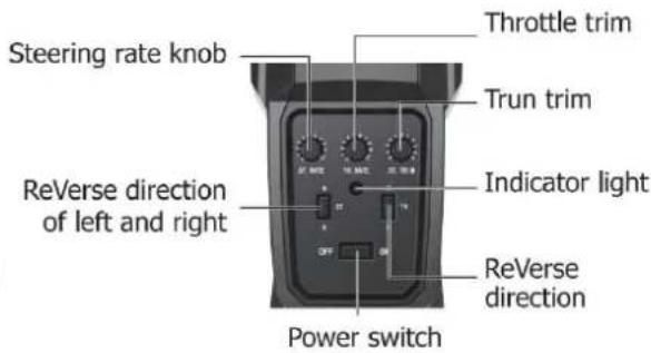
Remote Control 2
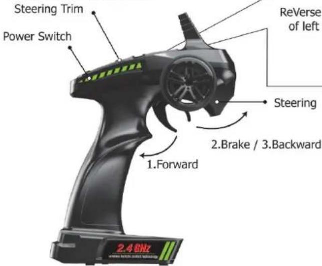
Steering rate knob
Reverse direction of left and right
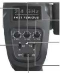
Throttle trim
Trun trim
Indicator light
ReVerse direction
Steering
2.Brake / 3.Backward
2.4GHz
- When the trigger is pulled back, the vehicle advances
- When the vehicle is moving forward, push the trigger forward and the vehicle will brake;
- When the trigger on the remote control returns to the midpoint, push the trigger forward again and the vehicle will retreat.
| LED color/pattern | Name | Hints |
| Red light always on | Normal driving pattern | |
| Red light with slow flash (on at 0.5s/off at 0.5s) | Hint of low power | For more information m please refer to operation of putting new battery into remote on page 6. |
| Red light with quick flash (on at 0.125s/off at 0.125s) | Connect failed/error | If transmitter and receiver are bound unsuccessfully, please close the remote system and restart for recovering normal operation. Please check exceeding scope, low battery or damaged antenna if the connection is failed. |
OPERATION
RC CAR BATTERY
① Take out the clip and open the battery cover.
② Connect the battery outlet to the cable in the battery compartment, then insert the battery to the batter compartment.
③ Close the battery cover and lock it.
If the car will not be used for a long time, make sure to turn it off and remove the battery.
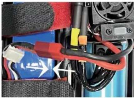
natural_image
Close-up of a battery pack with red and blue wires, no visible text or symbolsREMOTE CONTROL BATTERY
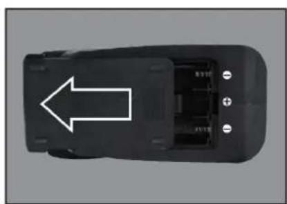
natural_image
Top-down view of a black car component with a white arrow pointing to the side (no text or symbols visible)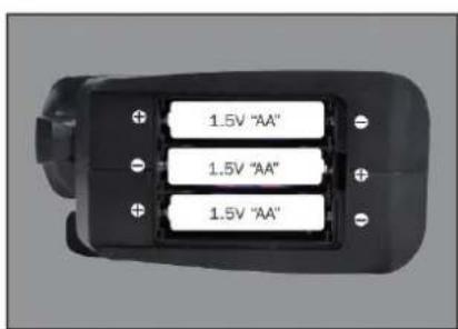
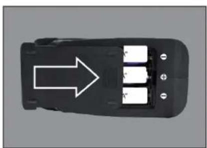
natural_image
Top-down view of a black car interior with three battery cells and an arrow pointing to one (no text or symbols)① Push the battery cover out.
② Insert 3 AA batteries (not included) in the correct direction.
③ Push the battery cover in.
If the remote will not be used for a long time, make sure to turn it off and remove the batteries.
When the battery of the remote control is low, the indicator light of the remote control will flash slowly.
OPERATION
PAIRING
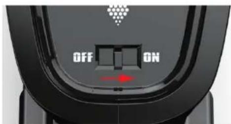
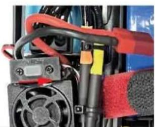
natural_image
Close-up of a mechanical device with red and black components, no visible text or symbols① Make sure the battery is charged.
② Insert batteries to the car and the remote.
③ Turn on the car power switch and the remote power switch. (DO NOT pull the throttle trigger during pairing)
④ Both will automatically pair. (The remote power indicator and the car power indicator will flash while waiting for the pairing process and will turn solid once pairing has been successful)
FREQUENTLY ASKED QUESTIONS
FORWARD, REVERSE, TURN LEFT, TURN RIGHT
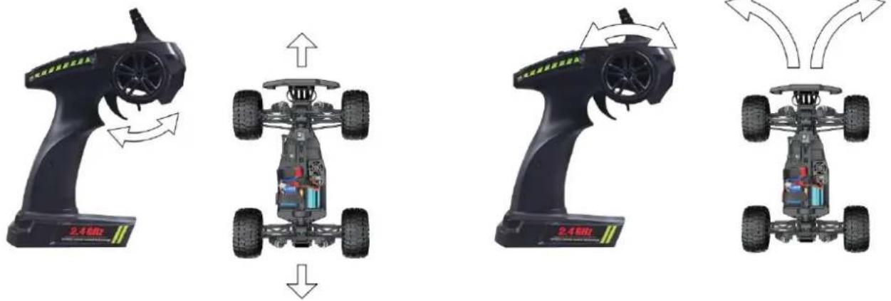
Pull the throttle trigger backward, the car goes forward. Push the throttle trigger forward, the car brakes, then push the throttle trigger forward again, the car goes reverse. (The throttle controls the speed)
Turn the steering control wheel counterclockwise, the car turns left. Turn the steering control wheel clockwise, the car turns right. ( Control the Steering Wheel Rotation Angle can control the degree of turning )
MAXIMUM SPEED CONTROL
Steering Rate Knob
Use the Steering Rate Knob to adjust direction angle when the steering wheel operated.
Increase the steering angle
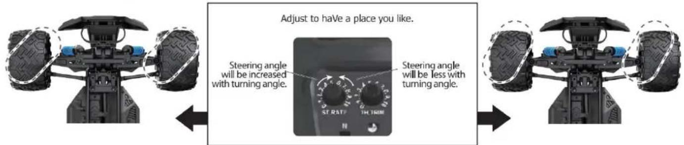
FINE TUNING KNOB OF STEERING
Use throttle to adjust the speed into your ideal one by rotate left or rotate right
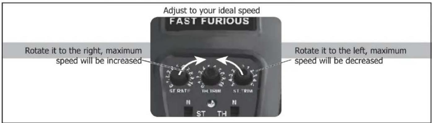
| QUESTION | CAUSE | SOLUTION |
| No match or can't control it | 1. The car battery or remote control battery is completely dead2. Out of remote range | 1. Replace charged battery2. Repair and keep in remote distance |
| Can't go forward or reverse | 1. Low battery2. The car shorted out when it got wet3. Poor contact between motor and electronic regulator | 1. Charging2. Let the car dry completely3. Reconnect the connection wire between the motor and the electronic regulator |
| Can't turn left or turn right | 1. The steering angle knob(ST.RATE) is set to minimum2. Low battery3. The car shorted out when it got wet3. Poor contact between steering gear and electronic regulator | 1. Set the steering angle knob (ST.RATE) to maximum2. Charging3. Let the car dry completely4. Reconnect the connection wire between the steering gear and the electronic regulator |
| It won't charge | 1. The output voltage or current of the power supply is too high2. The charging cable or battery is broken | 1. The output voltage and current of the power supply should be 5V 0.5~2A2. Kontakta kundtjänst |
| Something's missing or broken | Kontakta kundtjänst | |
| The wheels turn on their own | Pull the throttle trigger during pairing | Repair without pulling the throttle |
SPECIFICATIONS
Motor:
Battery:
Remote frequency:
Remote distance:
Charging mode:
Borstmotor
7,4V lithium battery
2.4GHz
100m
USB balance charging cable
DEVICE EXPLOSION DIAGRAM
9200 ASSEMBLY VIEW
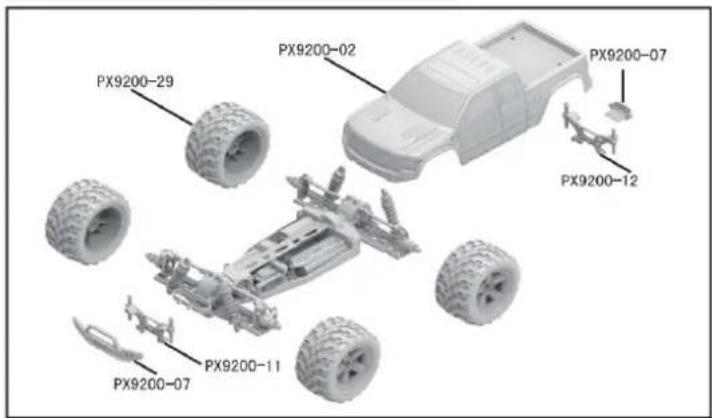
9203 ASSEMBLY VIEW
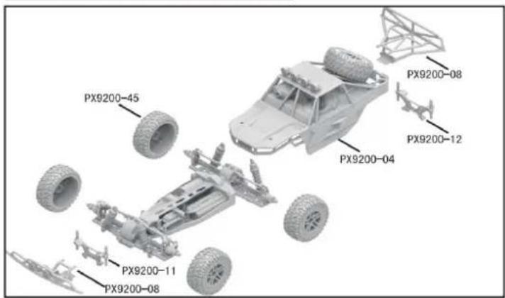
9204 CAR BOBY
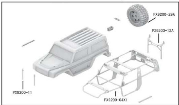
DRIVE AXLE EXPLODED VIEW
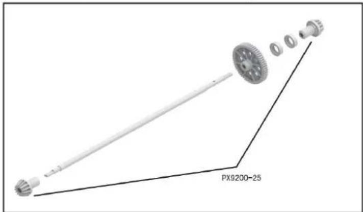
9202 ASSEMBLY VIEW

9203 CAR BOBY
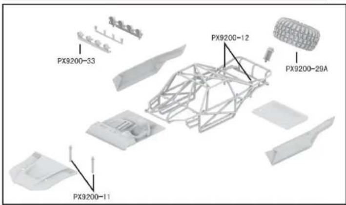
FRONT & REAR DIFFERENTIAL EXPLODED VIEW
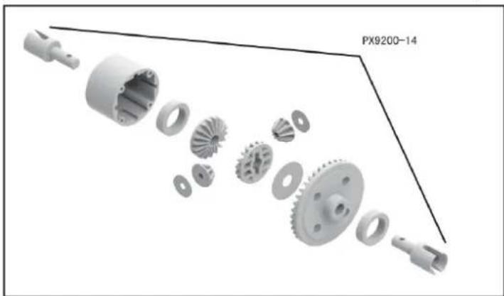
natural_image
Exploded view diagram of a mechanical gear assembly (no text or symbols)TIRE & WHEEL AXLE EXPLODED VIEW
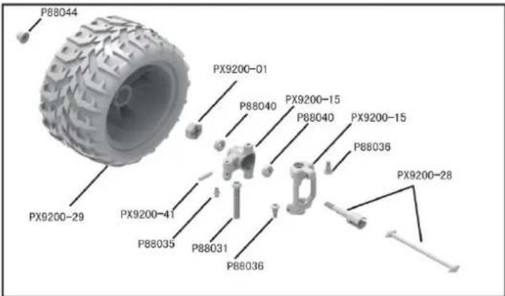
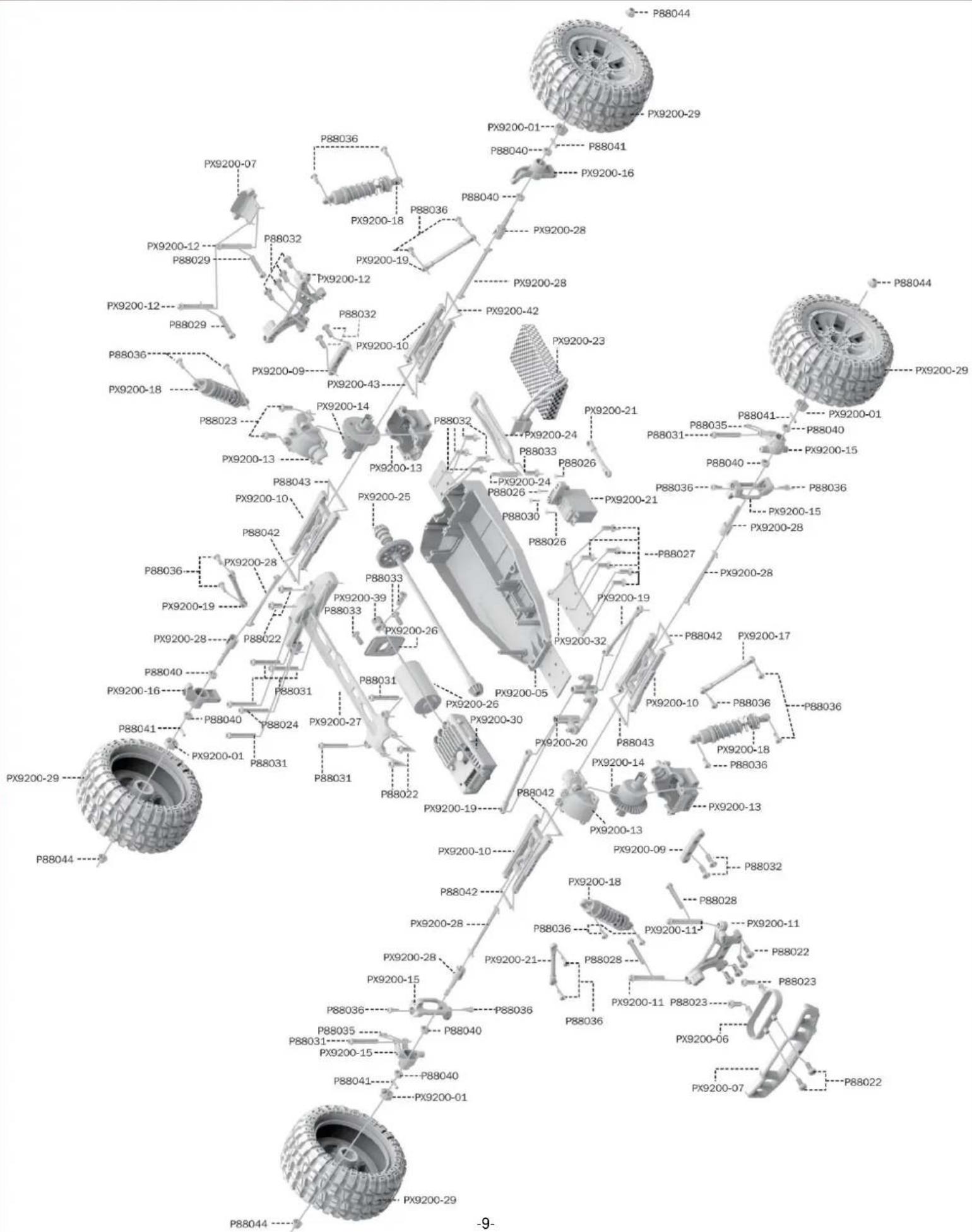
RETAIL ACCESSORY VIEW
PX9200-22
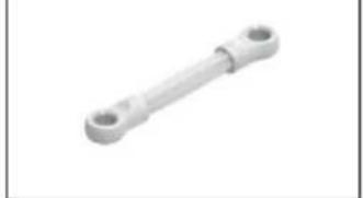
natural_image
Metal mechanical component with two circular ends (no text or symbols visible)Servo Link
PX9200-05
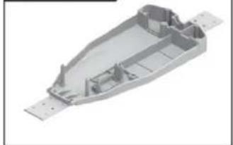
natural_image
3D rendering of a mechanical housing component with visible internal ribs and mounting holes (no text or symbols)Chassis
PX9200-06
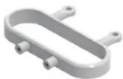
natural_image
3D rendering of a U-shaped mechanical component with two side ports (no text or symbols)Tube-style bumpers
PX9200-07
9200-Front/Rear Bumper
PX9200-09
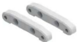
Tie Bar
PX9200-10
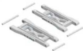
natural_image
Three identical mechanical component designs with no visible text or symbolsLower Supension Arm
PX9200-11
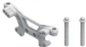
natural_image
Mechanical component with three screws, no visible text or symbolsFront Shock Tower and Body Post
PX9200-08
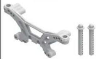
natural_image
Mechanical component with two screws and a bracket, no visible text or symbolsRear Shock Tower and Body Post
PX9200-13
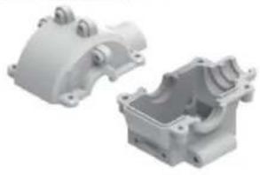
natural_image
Two white plastic mechanical parts, one open and one closed, with no visible text or symbols.Front/Rear Gear Box
PX9200-14
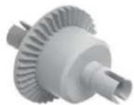
Diff Main Gear Complete
PX9200-15
Front Steering Carrier
PX9200-16
Rear Upright
PX9200-17
Front/Rear Upper Link
PX9200-18
natural_image
Two metallic spring components with bolts and small pins, no text or symbols visibleFront/Rear Shock Absorber
PX9200-19
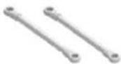
Steering Link
PX9200-20
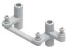
Steering Arm Complete
PX9200-51
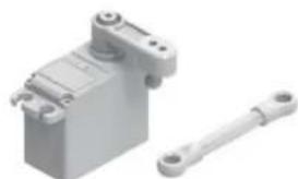
natural_image
3D rendering of a mechanical device with a shaft and housing (no text or symbols visible)Servo (3 trådar)
RETAIL ACCESSORY VIEW
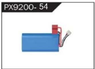
natural_image
Blue battery with red connector and wire, labeled PX9200-54 (no other text or symbols)LIPO Battery (7.4V 4000MAH)
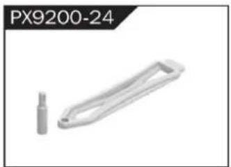
natural_image
Metallic mechanical component with a cylindrical pin and handle, labeled PX9200-24 (no other text or symbols)Battery Cover
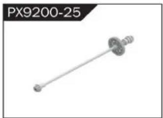
natural_image
Mechanical component labeled PX9200-25, showing a shaft with flanged ends and a central hub (no text or symbols on the part itself)Drive Shaft Assembly
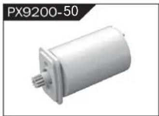
natural_image
Exterior view of a white cylindrical mechanical component (no text or symbols visible)Borstlös Motor
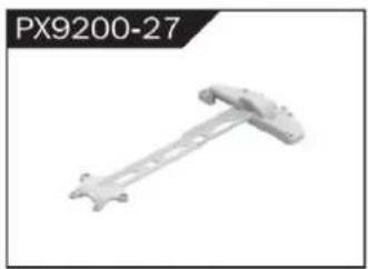
natural_image
Mechanical component labeled PX9200-27, showing a rod-like structure with mounting holes (no text or symbols on the part itself)Motor Layering
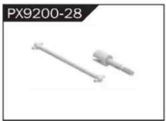
natural_image
Two mechanical components, one straight and one cylindrical, shown without any text or symbols.Universal Drive Joint
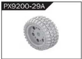
natural_image
3D rendered tire component labeled PX9200-29A, showing textured surface and mounting holes (no text or symbols on the object itself)Vacuum Wheel Complete
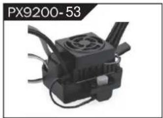
natural_image
Close-up of a black industrial device with cooling fan and cooling fins (no visible text or symbols)ESC

natural_image
3D model of a white plastic mechanical part with mounting holes (no text or symbols visible)Chassis Sheet Steel
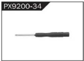
natural_image
Close-up of a black screwdriver with a metallic tip, labeled PX9200-34 (no other text or symbols visible)3MM Crosstip Screwdrivers
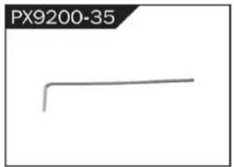
natural_image
Simple line drawing of a bent pipe or rod (no text or symbols)2MM Hexagon Wrench
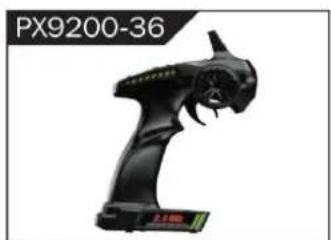
natural_image
Black handheld device labeled PX9200-36, showing a stylized creature with no visible text or symbols on the device itself.I 2.4G Transmitter for all

II 2.4G Transmitter for all
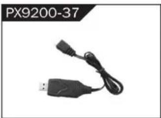
natural_image
Black USB connector with attached cable, labeled PX9200-37 (no other text or symbols visible)7,4V- USB
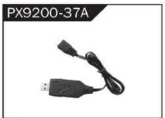
natural_image
Black USB device with attached cable and connector, labeled PX9200-37A (no other text or symbols visible)11,1V- USB
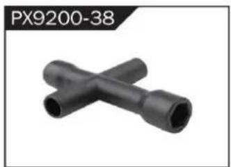
natural_image
Two black X-shaped pipe fittings (no text or symbols visible)Socket Wrench
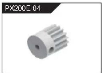
natural_image
3D rendered image of a white mechanical gear or rotor component (no text or symbols visible)Motorväxel (17t)
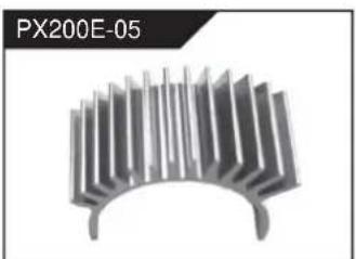
natural_image
Metallic heat sink component with radial fins, no visible text or symbolsnatural_image
Group of metallic screw-like components arranged in two rows (no text or symbols visible)Φ2.6*7PB Round Head Screw
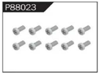
natural_image
Group of identical metallic screw-like components arranged in two rows (no text or symbols visible)Φ2.6*10PB Round Head Screw
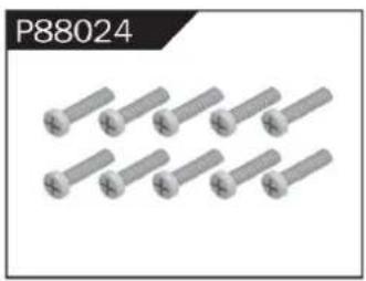
natural_image
Group of eight identical metallic bolts arranged in two rows (no text or symbols visible)Φ2.6*30PB Round Head Screw
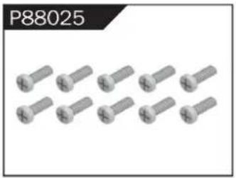
natural_image
Group of metallic screw-like components arranged in two rows (no text or symbols visible)Φ3*12 Round Head Screw
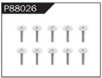
natural_image
Grid of nine identical screw-like components arranged in two rows (no text or symbols visible)Φ2.3*10PB Screw
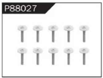
natural_image
Grid of nine identical screw-like components arranged in two rows (no text or symbols visible)Φ2.6*12PB Screw
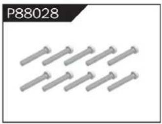
natural_image
Group of metallic bolts arranged in a row (no text or symbols visible)Φ1.7*8PB Screw
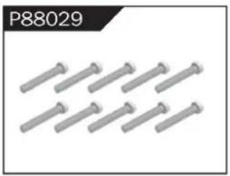
natural_image
Row of metallic bolts arranged in two rows (no text or symbols visible)Φ2*8PB Screw
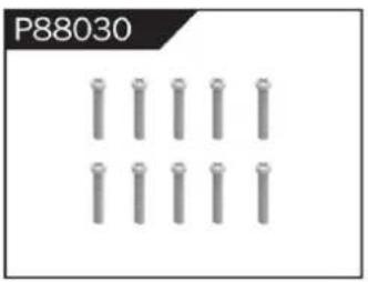
natural_image
Grid of metallic cylindrical pins arranged in three rows (no text or symbols)Φ2.3*14PB Screw
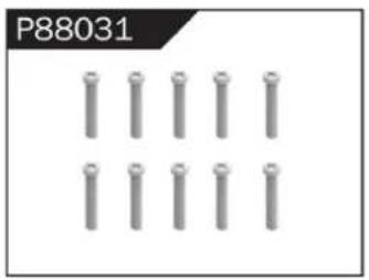
natural_image
Grid of metallic cylindrical pins arranged in three rows (no text or symbols)Φ2.6*14PB Screw
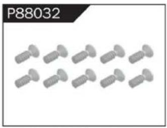
natural_image
Row of identical screw fasteners (no text or symbols visible)Φ2.6*10 Flattened Head Screw
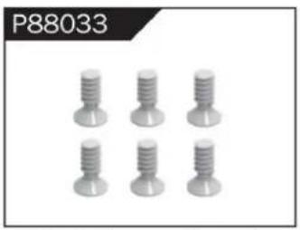
natural_image
Six identical screwdrivers arranged in two rows (no text or symbols visible)Φ3*8 Flattened Head Machine Screw
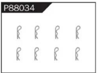
Body Clip
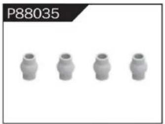
natural_image
Four identical cylindrical mechanical components arranged horizontally (no text or symbols visible)Hollow Ball Connectors
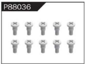
Step Screw
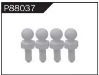
natural_image
Four stylized human figures in a row, no text or symbols presentΦ4.8 Ball Head
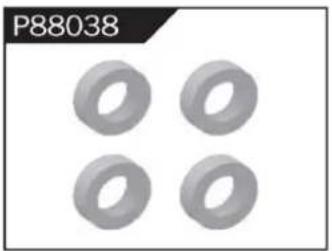
natural_image
Four identical gray ring-shaped objects arranged in a 2x2 grid (no text or symbols)Φ10*15*4 Ball Bearing
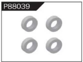
natural_image
Four identical gray ring shapes arranged in a 2x2 grid on a white background (no text or symbols)Φ8*10*3 Ball Bearing
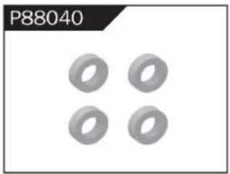
natural_image
Four identical gray ring shapes arranged in a 2x2 grid (no text or symbols)Φ5*9*3 Ball Bearing
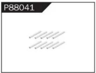
Φ1.5*10 Wheel Hex Pin c
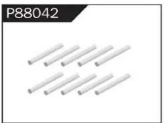
natural_image
Pure diagram of multiple parallel cylindrical rods without any text or symbolsΦ2.5*26.5 Steering Pin B
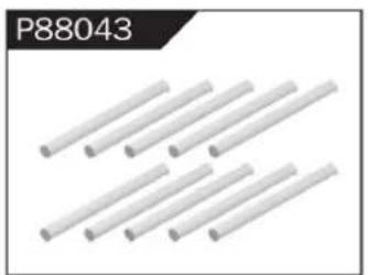
natural_image
Six white cylindrical rods arranged diagonally (no text or symbols visible)Φ3*48 Front/Rear Lower Suspension Pin A
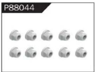
natural_image
Grid of 12 identical mechanical pipe fitting units, no text or symbols visibleNylor Nut M4
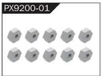
natural_image
12 gray hexagonal nuts arranged in two rows (no text or symbols visible)Wheel Hex
WARNINGS
- According to the instructions provided on the manual. Some part needs to be assembled and adjusted by adults.
- Please use under the guidance of an adult.
- Please promptly put away the packing materials so as not to cause harm to children.
- Do not operate on a location where water is trapped or under the rain. Parts of the product may malfunction if exposed to water.
- Do not touch the rotating wheel to avoid injury.
- The product contains small parts that may pose a risk of ingestion or suffocation.
- To remotely control the product on the road or in a crowd to avoid accidents.
- It is necessary to periodically check the charging USB cable, plug, housing and other components, and immediately unplug if found to be damaged.
- This product can only use the factory configured USB cable to charge the product battery.
- USB cable, battery box, and battery must be inserted into the same specified power supply as the product symbol.
- The USB charging cable and the battery is not a toy.
- Disconnect the rechargeable USB cable before cleaning the toy.
- If you observe electrical charges during product usage, turn off the device immediately.
- When installing or replacing the battery, pay attention to the correct polarity of the battery.
- The remote control car uses a 7.4V Lithium battery.
- It is strictly prohibited do the following actions such as but not limited to disassemble, modify, crash, puncture, drop, throw in a fire or any other means of causing damage to the product to avoid harm to the user and other participants.
- Do not expose the battery to prolonged exposure to sunlight to prevent danger.
- It is advisable to store the battery at a temperature below 30^ C. Do not store it in a place with heat, high temperature, or humidity to avoid danger.
- Non-rechargeable batteries cannot be charged.
- When charging a rechargeable battery, adult supervision is required.
- The rechargeable battery should be removed from the toy before charging.
- Do not mix old and new or different types of batteries.
- Only use the USB cable configured by this product when charging the battery.
- Do not disassemble the battery or modify the battery to avoid risk of fire or explosion.
- After the battery is used, it should be taken out of the remote control car. After cooling the battery, you can then charge it and placed it on a safe location. Unplug the battery outlet from the USB charging cable when not in used and disconnect the power line.
- Stop using the battery as soon as it gives a foul smells or suddenly becomes hot, deformed, discolored, or otherwise abnormal during use or charging.
- After the battery of the remote controller runs out, battery temperature is usually high and would recommend to wait for
30 minutes before charging the battery again. Otherwise, it may damage the battery. - Drained batteries should be removed immediately.
- Do not cause the electrical supply of the wiring port to short circuit.
- If you do not use the product for a long time, remove the batteries of the remote control car and remote control.
- instructions contains important product information, please give time to read for better product experience.
GENERAL INFORMATION
CAN NMB-3 (B)
RF Exposure
Radiation Exposure Statement:
This equipment complies with IC radiation exposure limits set forth for an uncontrolled environment. This equipment should be installed and operated with minimum distance 20cm between the radiator & your body.
BATTERY WARNING:
- Failure to follow all the instructions may result in serious injury, irreparable damage to the battery and may cause a fire, smoke or explosion.
- Always check the battery's condition before charging or using it.
- Replace the battery if damaged, gives a foul odor or show signs of overheating, discoloration, deformation and leakage.
- Never use anything other than the approval charger the battery. Always use a balancing charger for battery. It is recommended that you do not to use any other charger than the one provided with the product.
- The battery temperature must never exceed 60°C (140°F) otherwise the battery could be damaged or ignite.
- Never charge on a flammable surface, near flammable products or inside a vehicle (perferably place the battery in a non-flammable and nonconductive container).
- Never leave the battery unattended during the charging process. Never disassemble or modify the housing's wiring, or puncture the cells. Always ensure that the charger output voltage corresponds to the voltage of the battery. Do not overcharge the batter that may cause short circuit.
- Never expose the battery to moisture or direct sunlight, or store it in a place where temperatures could exceed 60^ C (car in the sun, for example).
- Always keep it out of reach from children.
- Improper battery use may result in a fire, explosion or other hazard.
- Non-rechargeable batteries are not be charge again. Rechargeable batteries are only to be charged with the supervision of an adult.
- Different types of batteries or new or used batteries which are different are not be mixed.
- Batteries are to be inserted with the correct polarity.
- The supply terminal should be used well to avoid short circuit. Examination of the transformer and battery charger regularly is encouraged to check any damage in the cord, plug, enclosure and other parts. If damage is observed, it must not be used until it has been repaired.
- The packaging has to be kept since it contains important information.
- The toy is only to be connected to Class II equipment bearing the symbol.
Adress: City, GuangDong-provinsen, KINA Pengxiang Building, Gangxia Road, Bumei Industrial Zone, ChenghaiArea, Shantou
EC REP: E-CrossStu GmbH
Mainzer Landstr.69, 60329 Frankfurt am Main.
UK REP: YH CONSULTING LIMITED.
C/O YH Consulting Limited Office 147, Centurion House, London Road, Staines-upon-Thames, Surrey, TW18 4AX
Importerad till AUS: SIHAO PTY LTD.
1 ROKEVA STREETEASTWOOD NSW 2122 Australien
Importerad till USA: Sanven Technology Ltd.
Suite 250, 9166 Anaheim Place, Rancho Cucamonga, CA 91730
VEVOR®
TOUGH TOOLS, HALF PRICE
www.vevor.com/support
- AllTerrainRemoteControlOff-RoadTruck
- MODEL:206E
- VEVOR®
- NEEDHELP?CONTACTUS!
- PREFACE
- CHARGING
- ATTENTION:
- RC CAR'S DETAILS
- BATTERY INSTALLATION
- REMOTE CONTROLLER
- OPERATION
- RC CAR BATTERY
- REMOTE CONTROL BATTERY
- PAIRING
- FREQUENTLY ASKED QUESTIONS
- MAXIMUM SPEED CONTROL
- FINE TUNING KNOB OF STEERING
- SPECIFICATIONS
- DEVICE EXPLOSION DIAGRAM
- RETAIL ACCESSORY VIEW
- WARNINGS
- GENERAL INFORMATION
- CAN NMB-3 (B)
- BATTERY WARNING:
- FCCInformation ((FCCID:2AMOZ9300E19880224)):
- CorrectDisposal
- WARNING:
- AVERTISSEMENT:
- TOUGH TOOLS, HALF PRICE
- BESOIN D'AIDE? CONTACTEZ-NOUS!
- All Terrain Afstandsbediening Off-Road Truck
- HULP NODIG? NEEM CONTACT MET ONS OP!
- FCC-informatie (FCC-(ID: 2AMOZ9300E19880224): )
- BEHÖVER HJÄLP? KONTAKTA OSS!
Brand : Vevor
Model : 206E
Category : Remote control toy