
PW1500S - Pressure washer BLACK & DECKER - Free user manual and instructions
Find the device manual for free PW1500S BLACK & DECKER in PDF.
| Product Type | Pressure Washer |
| Brand | Black & Decker |
| Model | PW1500S |
| Weight | 8 kg |
| Power Supply | 220-240 V ~ 50/60 Hz |
| Power | 1.5 kW |
| Maximum Pressure | 12 MPa |
| Nominal Pressure | 8.5 MPa |
| Water Flow Rate | 6 L/min |
| Max Inlet Water Temperature | 50 °C |
| Inlet Water Pressure | 0.1 - 1 MPa |
| Motor Protection | IPX5 |
| Sound Pressure Level (LPA) | 81.2 dB(A) |
| Sound Power Level (LWA) | 89 dB(A) |
| Vibrations | 3.72 m/s² |
| Gun Type | With Child Safety |
| Adjustable Nozzle | Yes, Adjustable Spray |
| Detergent Tank | Yes, Integrated |
| Auto Shut-Off Device (TSS) | Yes |
| Included Accessories | Lance, Gun, HP Hose, Nozzle Cleaning Tool |
| Usage | Washing Vehicles, Facades, Patios |
Frequently Asked Questions - PW1500S BLACK & DECKER
User questions about PW1500S BLACK & DECKER
0 question about this device. Answer the ones you know or ask your own.
Ask a new question about this device
Download the instructions for your Pressure washer in PDF format for free! Find your manual PW1500S - BLACK & DECKER and take your electronic device back in hand. On this page are published all the documents necessary for the use of your device. PW1500S by BLACK & DECKER.
USER MANUAL PW1500S BLACK & DECKER
natural_image
Line drawing of a portable electric water heater with wheels and buttons (no text or symbols)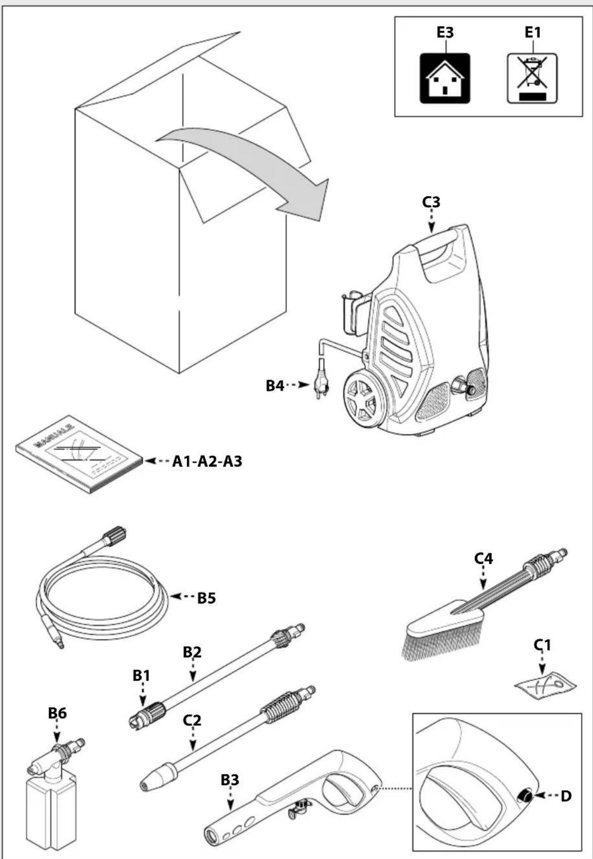
1

natural_image
Illustration of hands using a tool to adjust a mechanical component, with an inset showing the same assembly (no text or symbols present)2

natural_image
Illustration of hands using a handheld tool to adjust or install a cylindrical device (no text or symbols visible)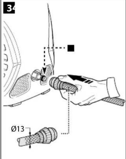
The image is too blurry to recognize any text content.
natural_image
Technical line drawing of a mechanical assembly with gears and a tool (no text or symbols)The image is too blurry to recognize any text content.

natural_image
Technical line drawing of a mechanical assembly with hands operating a tool (no text or symbols present)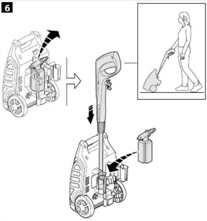
7
8
natural_image
Illustration of a hand using a tool to adjust a pipe, with a brush and arrow indicating motion (no text or symbols)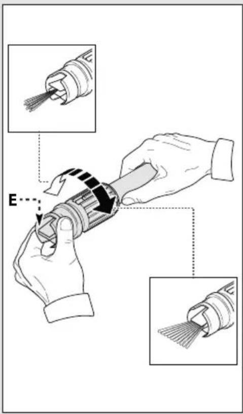

3

natural_image
Silhouette of a person spraying water with a pump, next to a mechanical device (no text or symbols)
natural_image
Simple 3D diagram of a rectangular object with an arrow labeled 'H' pointing upward (no text or symbols on the object itself)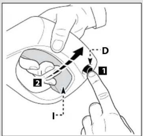
natural_image
Illustration of a hand pointing at a wall-mounted device with a labeled arrow indicating direction (no text or symbols beyond the label)4

natural_image
Illustration of two hands holding a screwdriver and a pen, showing the process with arrows indicating direction (no text or symbols present)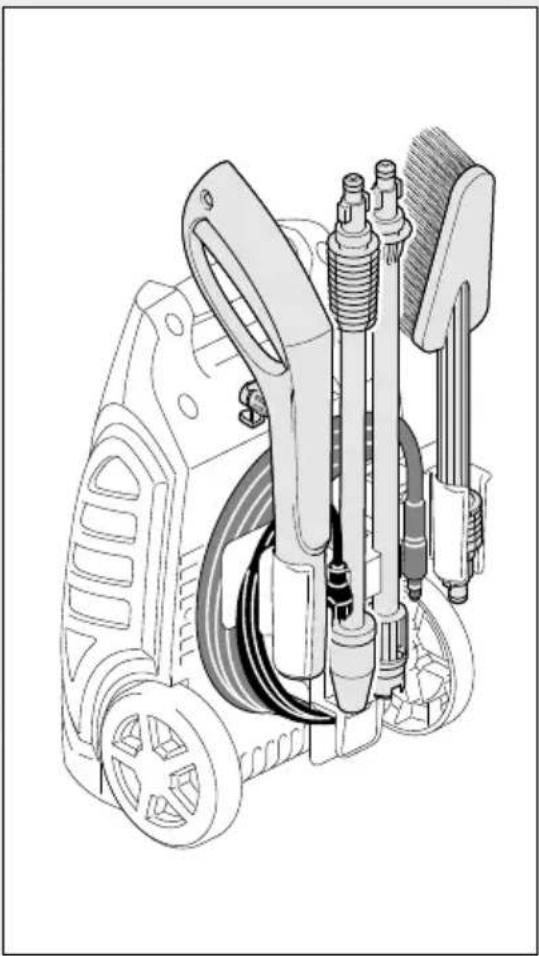
natural_image
Technical illustration of a mechanical device with hoses and components (no text or symbols)5
 |  Volt Volt |  ➞ 1 ÷ 25 m ➞ 1 ÷ 25 m |  ➞ 25 ÷ 50 m ➞ 25 ÷ 50 m |
| 230 2 x 1,5 mm | 2 | 2 x 2,5 mm 2 |

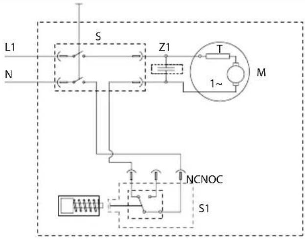
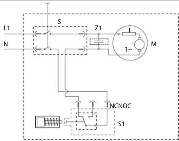
S = Switch
Z1 = Capacitor suppressor
T = Thermal protection
M = Motor
S1 = Pressure switch
1
ENGLISH
Safety instructions
The appliance you have purchased is a technologically advanced product designed by one of the leading European manufacturers of high pressure pumps. To obtain the best performance from your unit, read this booklet carefully and follow the instructions each time you use it. We congratulate you on your choice and wish you successful operation.
Safety rules/residual risks
Safety "must nots"
- Do not use the appliance with inflammable or toxic liquids, or any products which are not compatible with the correct operation of the appliance. Explosion or poisoning hazard
- Do not direct the water jet towards people or animals. Injury hazard
- Do not direct the water jet towards the unit itself, electrical parts or towards other electrical equipment. Electric shock hazard
- Do not use the appliance outdoors in case of rain. Short circuit hazard
- Do not allow children or incompetent persons to use the appliance. Injury hazard
- Do not touch the plug and/or socket with wet hands. Electric shock hazard
- Do not use the appliance if the electrical cable is damaged. Electric shock and short circuit hazard
- Do not use the appliance if the high pressure hose is damaged. Explosion hazard
- Do not jam the trigger in the operating position. Accident hazard
- Check that the data plates are affixed to the appliance, if not, inform your dealer. Units without plates must not be used as they are unidentifiable and potentially dangerous. Accident hazard
- Do not tamper with or adjust the setting of the safety valve or the safety devices. Explosion hazard
-
Do not alter the original diameter of the spray head nozzle. Hazardous alteration of operating performance
-
Do not leave the appliance unattended. Accident hazard
- Do not move the appliance by pulling on the electrical cable. Short circuit hazard
- Make sure that cars do not drive over the high pressure hose.
- Do not move the appliance by pulling on the high pressure hose. Explosion hazard
- When directed towards tyres, tyre valves or other pressurised components, the high pressure jet is potentially dangerous. Do not use the rotating nozzle kit, and always keep the jet at a distance of at least 30 cm during cleaning. Explosion hazard
Safety "musts"
- All electrical conductors must be protected against the water jet. Short circuit hazard
• The appliance MUST ONLY BE CONNECTED to an adequate power supply in compliance with all applicable regulations. Electric shock hazard - The appliance may cause network noise DURING startup.
- Use of a safety residual current circuit-breaker (R.C.C.B.) will provide additional protection for the operator (30 mA). Models supplied without plug must be installed by qualified staff. Use only authorized electrical extension leads with suitable conductor gauge.
•
High pressure may cause parts to rebound: wear all the protective clothing and equipment needed to ensure the operator's safety. Injury hazard
- Before doing work on the appliance, remove the plug. Accidental start-up hazard
- Before pressing the trigger, grip the gun firmly to counteract the recoil. Injury hazard
- Comply with the requirements of the local water supply company. According to EN 12729 (BA), the appliance may only be connected to the mains drinking water supply if a backflow preventer valve with drain facility is installed in the supply hose. Contamination hazard
ENGLISH
- Maintenance and/or repair of electrical components must be carried out by qualified staff. Accident hazard
• DISCHARGE residual pressure before disconnecting the unit hose. Injury hazard - Before using the appliance, CHECK every time that the screws are fully tightened and that there are no broken or worn parts. Accident hazard
- Only use detergents which will not corrode the coating materials of the high pressure hose/electrical cable. Explosion and electric shock hazard
- Ensure that all people or animals keep a minimum distance of 16 yd. (15m) away. Injury hazard
General information (fig.1)
Use of the manual
This manual forms an integral part of the appliance and should be kept for future reference. Please read it carefully before installing/ using the unit. If the appliance is sold, the Seller must pass on this manual to the new owner along with the appliance.
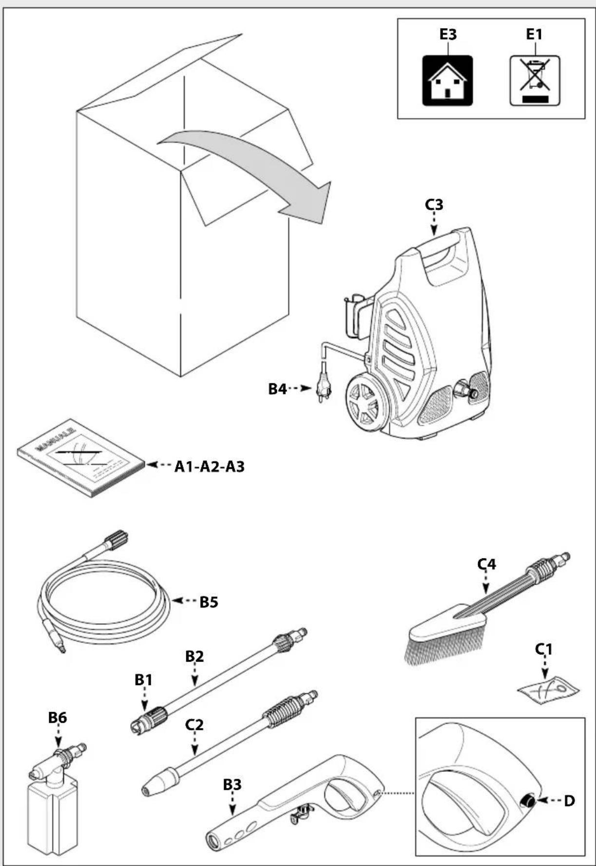
Delivery
The appliance is delivered partially assembled in a cardboard box. The supply package is illustrated in fig.1.
Documentation supplied with the appliance
• A1 Use and maintenance manual
• A2 Safety instructions
• A3 Declaration of conformity
• A4 Warranty regulations
Disposing of packaging
The packaging materials are not environmental pollutants but must still be recycled or disposed of in compliance with the relevant legislation in the country of use.
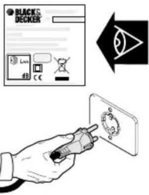
Safety signs
Comply with the instructions provided by the safety signs fitted to the appliance.
Check that they are present and legible; otherwise, fit replacements in the original positions.
E1 sign – Indicates that the appliance must not be disposed of as municipal waste; it may be handed in to the dealer on purchase of a new appliance. The appliance's electrical and electronic parts must not be reused for improper uses since they contain substances which constitute health hazards.
Symbols
2 symbol – Indicates that the appliance is intended for professional use, i.e. for experienced people informed about the relative technical, regulatory and legislative aspects and capable of performing the operations necessary for the use and maintenance of the appliance.
E3 symbol – Indicates that the appliance is intended for non-professional (domestic) use.
Technical information (fig.1)
Envisaged use
This appliance has been designed for individual use for the cleaning of vehicles, machines, boats, masonry, etc, to remove stubborn dirt using clean water and biodegradable chemical detergents. Vehicle engines may be washed only if the dirty water is disposed of as per regulations in force.
- Intake water temperature: see data plate on the appliance.
- Intake water pressure: min. 0,1MPa-max 1MPa.
- Operating ambient temperature: above 0ircC .
- The appliance is compliant with the EN 60335-2-79/A1 standard.
Operator
The symbol on the front cover identifies the appliance's intended operator (professional or non-professional).
Improper use
- Use by unskilled persons or those who have not read and understood the instructions in the manual is forbidden.
- The introduction of inflammable, explosive and toxic liquids into the appliance is prohibited.
- Use of the appliance in a potentially inflammable or explosive atmosphere is forbidden.
- The use of non-original spare parts and any other spare parts not specifically intended for the model in question is prohibited.
ENGLISH
- All modifications to the appliance are prohibited. Any modifications made to the appliance shall render the Declaration of Conformity null and void and relieve the manufacturer of all liability under civil and criminal law.
Main components
• B1 Adjustable spray nozzle
• B2 Lance
• B3 Gun with safety catch
• B4 Power supply cable with plug
• B5 High pressure hose
• B6 Detergent tank (on models with this feature)
Accessories (if included in the supply package – see fig.1)
• C1 Nozzle cleaning tool
• C2 Rotating nozzle kit
• C3 Handle
• C4 Brush
• C5 Hose reel
Safety devices
Caution - Danger!
Do not tamper with or adjust the safety valve setting.
- Safety valve and/or pressure limiting valve. The safety valve is also a pressure limiting valve. When the gun trigger is released, the valve opens and the water recirculates through the pump inlet or is discharged onto the ground.
- Thermostat valve (D1 where fitted) If the water temperature exceeds the temperature set by the manufacturer, the thermostat valve discharges the hot water and draws in an amount of cold water equal to the amount of water discharged, until the correct temperature is restored.
- Safety catch (D): prevents accidental spraying of water.
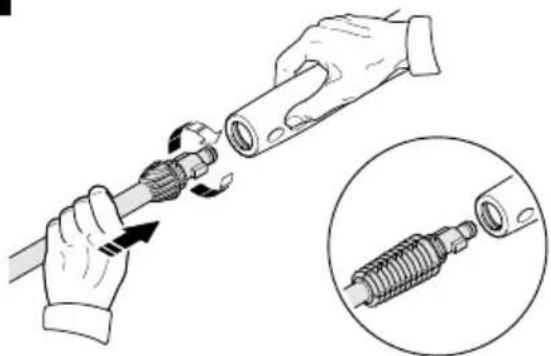
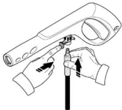
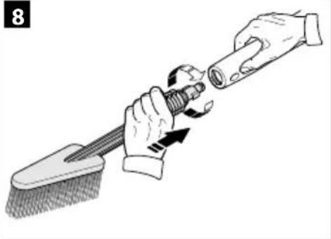
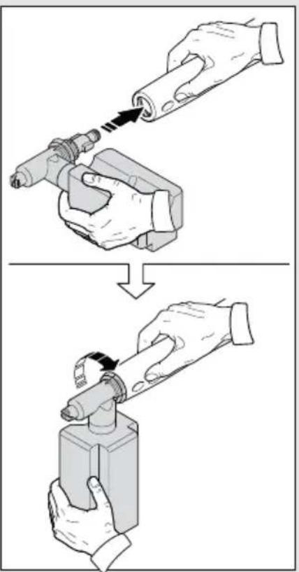
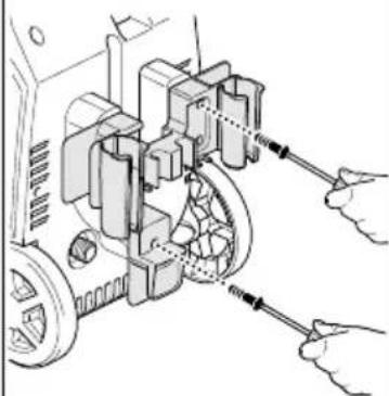
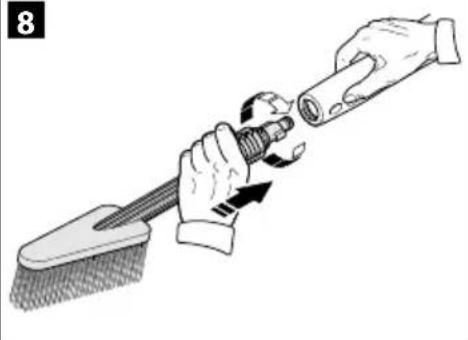
Installation (fig.2)
Assembly
Caution - Danger!
All installation and assembly operations must be
performed with the appliance disconnected from the mains power supply.
The assembly sequence is illustrated in fig.2.
Assembling the rotating nozzle
(For models with this feature)
The rotating nozzle kit delivers greater washing power. Use of the rotating nozzle may cause of reduction in pressure of 25% compared to the pressure obtained with the adjustable nozzle. However, the rotating nozzle kit delivers greater washing power due to the rotation of the water jet.
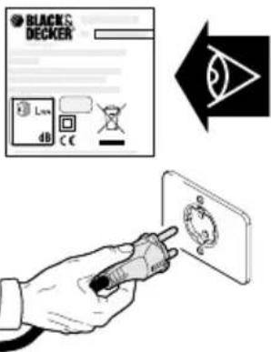
Electrical connection
Caution - Danger!
Check that the electrical supply voltage and frequency (V-Hz) correspond to those specified on the appliance data plate (fig.2). The appliance should only be connected to a mains power supply equipped with an adequate earth connection and a differential security breaker (30 mA) to cut off the electricity supply in the instance of a short circuit.
Use of extension cables
Use cables and plugs featuring "IPX5" protection level. The cross-section of the extension cable should be proportionate to its length; the longer it is, the greater its cross-section should be. See table I.
Water supply connection
Caution - Danger!
Only clean or filtered water should be used for intake. The delivery of the water intake tap should be equal to that of pump capacity.
Place the appliance as close to the water supply system as possible.
Connection points
• Water outlet (OUTLET)
• Water inlet with filter (INLET)
Connection to the mains water supply
The appliance can be connected directly to the mains drinking water supply only if the supply hose is fitted with a backflow preventer valve as per current regulations in force. Make sure that the hose is at least ∅ 13 mm and that it is reinforced.
Adjustment information (fig.3)
Adjusting the spray nozzle
(for models with this feature)
• Water flow is adjusted by regulating the nozzle (E).
Adjusting the detergent
(on models with this feature)
- Detergent flow is adjusted using the regulator (F).
Adjusting the detergent pressure
Set the adjustable nozzle (E) on " - " to deliver detergent at the correct pressure (on models with this feature).
Adjusting the pressure
(on models with this feature)
- The regulator (G) is used to adjust the working pressure. The pressure is shown on the pressure gauge (where fitted).
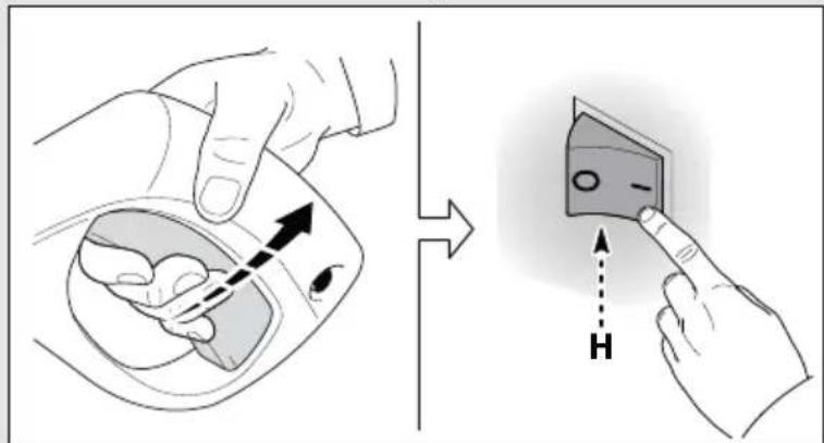
Information on use of the appliance (fig.4)
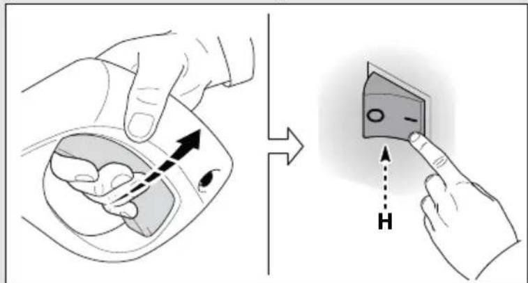
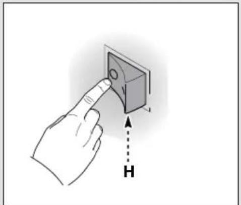
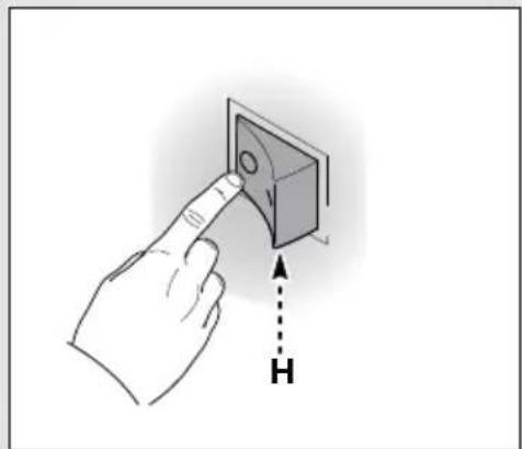
Controls
- Starter device (H).
Set the starter switch on (ON/1) to:
a) Start the motor (in models without TSS device);
b) Set the motor ready to start (in models with TSS device).
- If there is a pilot light on the starter device, it should light up.
- If the "low/high" settings are available, use them as follows:
- Low : low pressure washing
• High : high pressure washing
- Set the starter device switch on (OFF/0) to shut down the appliance.
- If there is a pilot light on the starter device, it should go out.
• Water jet control lever (I).

Caution - Danger!
During operation the appliance must be positioned as shown in fig. 4 on a sturdy, stable surface.
Start-up
1) Turn on the water supply tap fully.
2) Release the safety catch (D).
3) Depress the gun trigger for a few seconds and start up the appliance using the starter device (ON/1).
Caution - Danger!
Before starting up the appliance check that the water supply hose is connected properly; use of the appliance without water will damage it; do not cover the ventilation grilles when the appliance is in use.
TSS models - In TSS models with automatic delivery flow cut-off system:
- When the gun trigger is released the dynamic pressure automatically cuts out the motor (see fig.4);
- When the gun trigger is depressed the automatic drop in pressure starts the motor and the pressure is restored after a very slight delay;
- If the TSS is to function correctly all gun releasing and depressing operations must be performed at intervals of less than 4-5 seconds.
- On three-phase models for professional use, at first use start the appliance for a very short time to check that the motor is running in the correct direction. If the motor fan is turning anti-clockwise, exchange two of the three phase wires (L1, L2, L3) in the electrical plug.
- To prevent damage to the appliance, do not allow it to operate dry and when running do not stop the water jet for more than 10 minutes at a time (for models without TSS device).
Stopping the appliance
1) Set the starter device switch on (OFF/0).
2) Depress the gun trigger and discharge the residual pressure inside the hoses.
3) Engage the gun safety catch (D).
Restarting
1) Release the safety catch (D).
2) Depress the gun trigger and discharge the residual air inside the hoses.
3) Set the starter device on (ON/1).
ENGLISH
Storage
1) Switch the appliance off (OFF/0).
2) Remove the plug from the socket.
3) Turn off the water supply tap.
4) Discharge the residual pressure from the gun until all the water has come out of the nozzle.
5) Drain and wash out the detergent tank at the end of the working session. To wash out the tank, use clean water instead of the detergent.
6) Engage the gun safety catch (D).
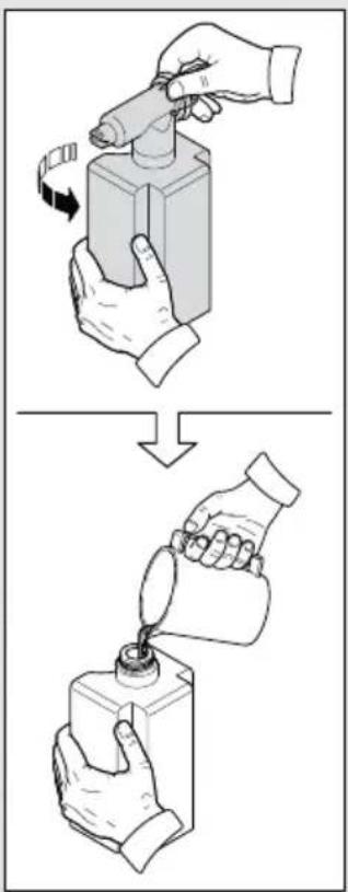
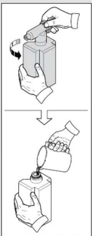
Refilling and using detergent
When using detergent, the adjustable nozzle must be set on "-" (on models with this feature).
Use of a high pressure hose longer than the one originally supplied with the cleaner, or the use of an additional hose extension, may reduce or completely halt the intake of detergent.
Fill the tank with highly degradable detergent.
Recommended cleaning procedure
Dissolve dirt by applying the detergent mixed with water to the surface while still dry.
When dealing with vertical surfaces work from the bottom upwards.
Leave the detergent to act for 1-2 minutes but do not allow the surface to dry. Starting from the bottom, use the high pressure jet at a minimum distance of 30 cm. Do not allow the rinse water to run onto unwashed surfaces.
In some cases, scrubbing with brushes is needed to remove dirt.
High pressure is not always the best solution for good washing results, since it may damage some surfaces. The finest adjustable nozzle jet setting or the rotating nozzle should not be used on delicate or painted parts, or on pressurised components (e.g tyres, inflation valves, etc.).
Effective washing depends on both the pressure and volume of the water used, to the same degree.
Maintenance (fig.5)
Any maintenance operations not covered by this chapter should be carried out by an Authorized Sales and Service Centre.

Caution - Danger!
Always disconnect the plug from the power socket before carrying out any work on the appliance.
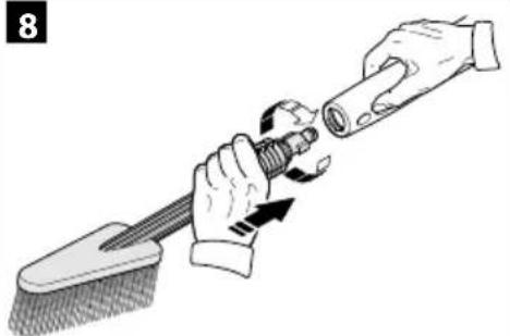
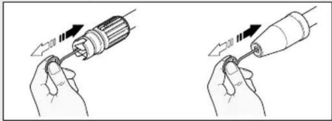
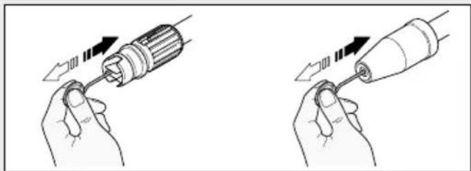
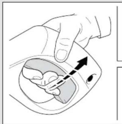
Cleaning the nozzle
1) Disconnect the lance from the nozzle.
2) Remove any dirt deposits from the nozzle hole using the tool (C1).
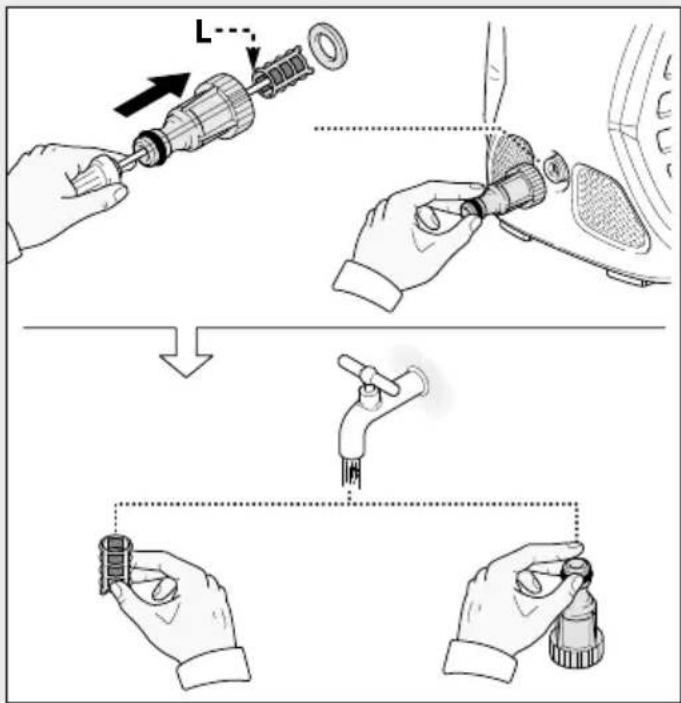
Cleaning the filter
Inspect the intake filter (L) and detergent filter (if fitted) before each use, and clean in accordance with the instructions if necessary.
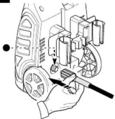
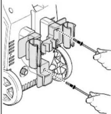
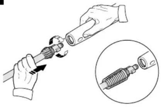
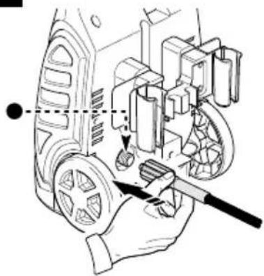
Unjamming the motor (on models with this feature)
In case of lengthy stoppages, limescale sediments may cause the motor to seize. To unjam the motor, turn the drive shaft with a tool (M).
End-of-season storage
Treat the appliance with non-corrosive, non-toxic antifreeze before storing it away for winter.
Put the appliance in a dry place, protected from frost.
Mains plug replacement (U.K. & Ireland only)
If a new mains plug needs to be fitted:
- Safely dispose of the old plug.
- Connect the brown lead to the live terminal in the new plug.
- Connect the blue lead to the neutral terminal.
Warning! No connection is to be made to the earth terminal. Follow the fitting instructions supplied with good quality plugs. Recommended fuse: 5 A.
Troubleshooting
| Problem | Possible causes | Remedy |
| Nozzle worn Replace nozzle | ||
| Water filter fouled Clean filter (L) | (fig.5) | |
| Water supply pressure low Turn on water supply tap fully | ||
| Air being sucked into system Check tightness of hose fittings | ||
| Pump does not reach Air in pump working pressure releasing the gun trigger until the water comes out in a steady flow. Switch the appliance back on again. | Switch off the appliance and keep depressing and adjustable nozzle not Turn the adjustable positioned correctly nozzle (E) (+) (fig.3) | |
| Adjustable nozzle not Turn the adjustable positioned correctly nozzle (E) (+) (fig.3) | ||
| Thermostatic valve tripped Wait for correct water temperature to be restored | ||
| Water intake from external tank Connect appliance to the mains water supply | ||
| Pressure drops during use Intake water too hot Reduce temperature | ||
| Nozzle clogged | Clean nozzle (fig.5) | |
| Intake filter (L) dirty | Clean filter (L) (fig.5) | |
| Insufficient power supply supply line is the same as that on the plate (fig.2) | Check that the voltage of the mains power | |
| Voltage loss due to use of Check motor “sounds” but fails to start characteristics of extension cable extension cable | ||
| Appliance not used for a long period of time | Contact your nearest Authorized Service Centre | |
| Problems with TSS device | Contact your nearest Authorized Service Centre | |
| No electrical power and that the mains voltage supply is present (*) | Check that the plug is firmly in the socket | |
| Motor fails to start | Problems with TSS device | Contact your nearest Authorized Service Centre |
| Appliance not used for a long period of time (in models with this feature) (fig.5) | Using the tool (M) unjam the motor from the hole at the rear of the appliance | |
| Seals worn | Have the seals replaced at your nearest Authorized Service Centre | |
| Water leakage | ||
| Safety valve tripped and discharging | Contact an Authorized Service Centre | |
| Appliance noisy | Water too hot | Reduce temperature (see technical data |
| Oil leakage | Seals worn | Contact your nearest Authorized Service Centre |
| TSS versions only: motor starts even with gun trigger is released | High pressure system or pump hydraulic circuit not watertight | Contact your nearest Authorized Service Centre |
| TSS versions only: no water delivery when gun trigger is depressed (with supply hose connected) | Nozzle clogged | Clean nozzle (fig.5) |
| Detergent too dense | Adjustable nozzle on high pressure setting | Set nozzle on "-" setting (fig.3) |
| No detergent taken in | Dilute with water | |
| If the problem persists, contact an Authorized Service Centre | High pressure hose extension being used | Fit original hose |
| Deposits or restriction in detergent circuit | Flush with clean water and eliminate any restrictions. |
(*) If the motor starts and does not restart during operation, wait 2-3 minutes before repeating the start-up procedure (overload cutout has been tripped). If the problem recurs more than once, contact your nearest Authorized Service Centre.
Declaration of conformity
CE
We declare under our sole responsibility that this product is in conformity with the following standards or standardized documents
EN 60335-1 - EN 60335-2-79; EN 55014-1; EN 55014-2;
EN 61000-3-2; EN 61000-3-3; EN 61000-3-11; EN 60704-1
In accordance with the regulations:
2006/42/CE, 2006/95/CE, 2002/95/CE, 2002/96/CE, 2004/108/CE, 2000/14/CE
For more information, please contact Black & Decker at the following address or refer to the back of the manual. The undersigned is responsible for compilation of the technical file and makes this declaration on behalf of Black & Decker.

Kevin Hewitt
Vice-President Global Engineering
Black & Decker Europe, 210 Bath Road, Slough,
Berkshire, SL1 3YD
United Kingdom
04/02/2013
Technical Data
| Unit PW1500 | ||
| Output L/min 6 | ||
| Pressure MPa 8,5 | ||
| Maximum pressure MPa 12 | ||
| Power kW 1,5 | ||
| T° input °C 50 | ||
| Maximum input pressure MPa 1 | ||
| Repulsive force of the gun to the maximum pressure N 9,4 | ||
| Motor Insulation | - | Class F |
| Motor Protection | - | IPX5 |
| Voltage | V/Hz | 220-240~1 |
| Maximum allowed net impedance | Ω | - |
| Sound level (K=3 dB(A)) : LPA (EN 60704-1) | dB (A) | 81,2 |
| LWA (EN 60704-1) | dB (A) | 89 |
| Unit vibrations (K=1,5M/s2) | M/s2 | 3,72 |
| Weight | kg | 8 |
Protecting the environment

ate collection. This product must not be disposed of with normal household waste.
Should you find one day that your Black & Decker product needs replacement, or if it is of no further use to you, do not dispose of it with other household waste. Make this product available for separate collection.
- Black & Decker provides a facility for recycling Black & Decker products once they have reached the end of their working life. This service is provided free of charge. To take advantage of this service please return your product to any authorised repair agent who will collect them on our behalf.
- You can check the location of your nearest authorised repair agent by contacting your local Black & Decker office at the address indicated in this manual. Alternatively, a list of authorized Black & Decker repair agents and full details of our after-sales service and contact are available on the Internet at: www.2helpU.com.
Warranty
Black & Decker is confident of the quality of its products and offers an outstanding warranty.
This warranty statement is in addition to and in no way prejudices your statutory rights.
If a Black & Decker product becomes defective due to faulty materials, workmanship or lack of conformity, within 24 months from the date of purchase, Black & Decker warranty to replace defective parts, repair products subjected to fair wear and tear or replace such products to ensure minimum inconvenience to the customer unless:
- The product has been used for trade, professional or hire purposes;
- The product has been subjected to misuse or neglect;
- The product has sustained damage through foreign objects, substances or accidents;
• Repairs have been attempted by persons other than authorised repair agents or Black & Decker service staff.
To claim on the warranty, you will need to submit proof of purchase to the seller or an authorised repair agent. You can check the location of your nearest authorised repair agent by contacting your local Black & Decker office at the address indicated in this manual.
Alternatively, a list of authorised Black & Decker repair agents and full details of our after-sales service and contacts are available on the Internet at: www.2helpU.com.
1
natural_image
Illustration of hands using a tool to adjust a mechanical component, with an inset showing the same component (no text or symbols present)2
natural_image
Illustration of hands using a handheld tool to adjust or install a device (no text or symbols visible)
The image is too blurry to recognize any text content.

natural_image
Illustration of a hand using a tool to adjust or install a mechanical component, with no visible text or symbols.The image is too blurry to recognize any text content.
natural_image
Technical line drawing of a mechanical assembly with hands operating a tool (no text or symbols present)
7

8
natural_image
Illustration of a hand using a tool to adjust a brush (no text or symbols present)

3

natural_image
Silhouette of a person spraying water with a pump, next to a mechanical device (no text or symbols)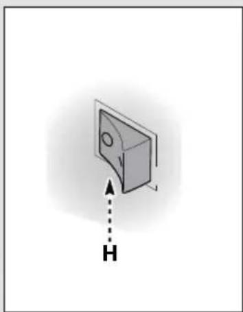
natural_image
Simple 3D diagram of a rectangular object with a circular hole and an upward arrow labeled 'H' (no text or symbols beyond the label)

natural_image
Illustration of a hand pressing a button on an electrical outlet, with a dashed arrow labeled 'H' pointing to the button (no text or symbols beyond the label)4

natural_image
Illustration of two hands holding a screwdriver and a pen, showing the process with arrows indicating direction (no text or symbols present)
natural_image
Technical illustration of a mechanical device with hoses and components (no text or symbols)5
 |  Volt Volt |  1 ÷ 25 m 1 ÷ 25 m |  25 ÷ 50 m 25 ÷ 50 m |
| 230 2 x 1,5 mm | 2 | 2 x 2,5 mm 2 |
S = Switch
Z1 = Capacitor suppressor
T = Thermal protection
M = Motor
S1 = Pressure switch
1
FRANÇAIS
Informations techniques (fig.1)
Utilisation prévue
Installation (fig.2)
Montage

Attention – danger!
2006/42/CE, 2006/95/CE, 2002/95/CE, 2002/96/CE, 2004/108/CE, 2000/14/CE
Vice-President Global Engineering
Black & Decker Europe, 210 Bath Road, Slough,
Berkshire, SL1 3YD
Royaume-Uni
04/02/2013
Données Techniques
• يجب حماية جميع موصلات الكهرباء من رشاش国会. players 4 players 5 players 6 players 7 players 8 players 9 players 10 players 11 players 12 players 13 players 14 players 15 players 16 players 17 players 18 players 19 players 20 players 21 players 22 players 23 players 24 players 25 players 26 players 27 players 28 players 29 players 30 players 31 players 32 players 33 players 34 players 35 players 36 players 37 players 38 players 39 players 40 players 41 players 42 players 43 players 44 players 45 players 46 players 47 players 48 players 49 players 50 players 51 players 52 players 53 players 54 players 55 players 56 players 57 players 58 players 59 players 60 players 61 players 62 players 63 players 64 players 65 players 66 players 67 players 68 players 69 players 70 players 71 players 72 players 73 players 74 players 75 players 76 players 77 players 78 players 79 players 80 players 81 players 82 players 83 players 84 players 85 players 86 players 87 players 88 players 89 players 90 players 91 players 92 players 93 players 94 players 95 players 96 players 97 players 98 players 99 players 100
natural_image
Illustration of two hands holding a screwdriver, showing the process with arrows indicating direction (no text or symbols present)
natural_image
Technical illustration of a cleaning or cleaning tool assembly (no text or symbols visible)5
 |  Volt Volt |  1 ÷ 25 m 1 ÷ 25 m |  25 ÷ 50 m 25 ÷ 50 m |
| 230 2 x 1,5 mm | 2 | 2 x 2,5 mm 2 |
S مفتاح
natural_image
Illustration showing a hand pouring liquid from a bottle into a container using a tool (no text or symbols present)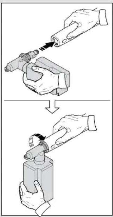
3

natural_image
Silhouette of a person using a water spray gun to clean a car (no text or symbols)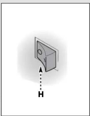
natural_image
Simple 3D diagram of a box with an arrow labeled 'H' pointing upward (no text or symbols on the box itself)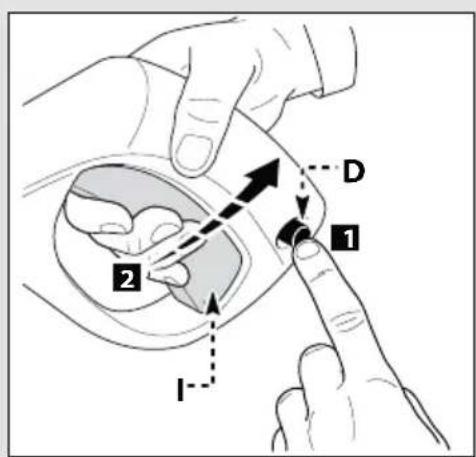
natural_image
Illustration of a hand inserting a device into a container with an arrow indicating direction (no text or symbols)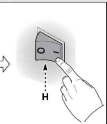
natural_image
Illustration of a hand pressing a button on a wall-mounted device with an arrow labeled 'H' indicating direction (no text or symbols beyond the label)4
1
natural_image
Illustration of hands using a screwdriver to adjust a mechanical component, with an inset showing the same tool (no text or symbols present)2

natural_image
Illustration of hands using a handheld tool to adjust or install a mechanical component (no text or symbols visible)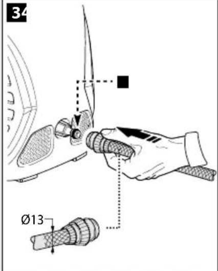
The image is too blurry to recognize any text content.
natural_image
Illustration of a hand using a tool to adjust or install a mechanical component, with no visible text or symbols.The image is too blurry to recognize any text content.
natural_image
Technical line drawing of a mechanical assembly with hands operating a tool (no text or symbols present)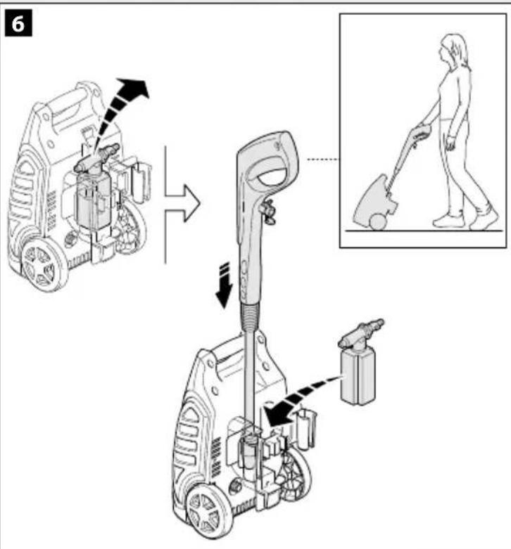
7
8
natural_image
Illustration of a hand using a tool to adjust a broom, no text or symbols present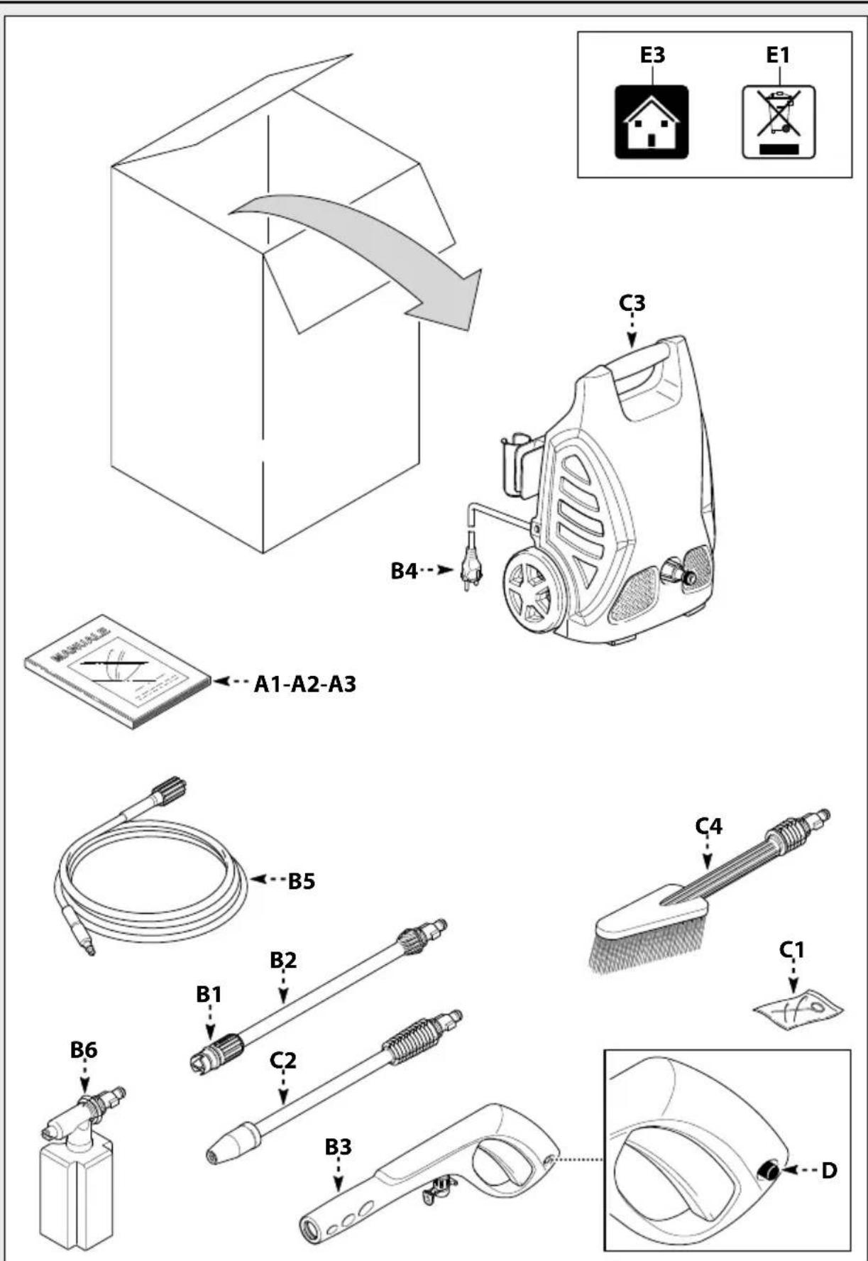
Names & Addresses for Black & Decker Service Concessionaries
ALGERIA: SARL Outillage Corporation, After Sale Service Center-08, Rue Mohamed Boudiaf - Cheraga, Algiers, Algeria, Tel: +213 21 375131, Fax: +213-0-369667. BAHRAIN: Alfouz Services Co. WLL, P.O. Box 26562, Tubli, Manama, Tel: +973-17783562 / 17879987, Fax: +973-17783479. EGYPT: Anasia Egypt for Trading S.A.E, P.O. Box 2443, 9, Mostafa Refaat Street, Sheraton Heliopolis 11361, Cairo, Tel: +202-22684159, Fax: +202-22684169. ETHIOPIA: Seif Sherif Trade PLC -Arada Sub City, Kebele 01-02, Global Insurance Bldg., 2nd Flr. Room 43, P.O.Box 2525, Addis Ababa, Ethiopia, Tel: 00-251-11-1563968/ 1563969, Fax: 00-251-11-1558009. IRAQ: Financial Links, Kazzaz Building Arasat Al-Hindia Block No: 629 Street: 31Building No: 1 Baghdad – Iraq, Tel: +964 (0)780 195 2223 /+ 964 (0)781 3763044. JORDAN: Bashiti Hardware, 93 King Abdullah 2nd St., Opp ELBA House, P.O. Box 3005, Tel: +962-6-5349098 ext.11, Fax: +962-6-5330731. KENYA: Leading Concepts, P.O. Box: 40877-00100, Nairobi, Kenya. Tel: +254 20 690 5000, Fax: +254 20 690 5111. KUWAIT: Al Omar Technical Co., P.O. Box 4062, Safat 13041, Kuwait, Tel: +965-24848595 / 24840039, Fax: +965-24845652. LEBANON: Aces Service Centre, P.O. Box 90-102, Nahr El Mot, Seaside Highway, Pharaon Building, Beirut. Tel: 00961-1-898989, Fax: 00961-1-245880. LIBYA: Homeworld Co., Building No.5, Senidal St., Amr Ibn Elaas Road, Benghazi, Libya. Tel: 00218-61-9094183. Service Center1 - Benghazi: Tel: +218-061-3383994, Fax: +218-092-7640688, Service Center2 - Tripoli: Tel: +218-021-3606430, Fax: +218-092-6514813. MALTA: John G Cassar Ltd. 36-Victory Street, Qormi QRM 06, Malta. Tel: +356-21493251, Fax: +356-21483231. MAURITIUS: J.M. Goupille & Co. Ltd., Rogers Industrial Park 1, Riche Terre, Mauritius, Tel: +230 206 9450/ +230 207 1700, Fax: +230 206 9474/ +230 248 3188. MOROCCO: UATS, No. 37, Lotissement KADIRIA, km 10 Route Eljadida - LISASSFA, Casablanca, Morocco, Tel: +212 522652602, Fax: +212522652603. NIGERIA: Dana Electronics Ltd. (Lagos) 116/ 120, Apapa Oshodi Express Way, Isolo, Lagos, Nigeria. Tel: +234-17431818/ +234-8037767774/ +234-8057445477. (Abuja) 18, A.E. Ekukinam Street, Off Obsfemi Awolowo Road, Utako, Abuja, Nigeria. Tel: +234-8032276101/ +234-8037767774. (Kano) 9A - Mai Malari Road, Bompai, Kano, Nigeria. Tel: +234-8053294947/ +234-8037767774. OMAN: Oman Marketing & Service Co. (Omasco), P.O. Box 2734, Behind Honda Showroom, Wattayah, Oman, Tel: +968-24560232/ 24560255, Fax: +968-24560993. Oman Marketing & Service Co. (Omasco), Al Ohi, Sohar, Oman, Tel: +968-26846379, Fax: +968-26846379. Oman Marketing & Service Co. (Omasco) - Sanaya, Salalah, Oman, Tel: 00968-23212290, Fax: +968-23210936. PAKISTAN: Ammar Service & Spares - 60-Bank Arcade, Serai Road, Karachi, Pakistan, Tel: 0092-21-32426905, Fax: 0092-21-32427214. QATAR: Al Muftah Service Centre, Al Wakrah Road, P.O. Box 875, Doha, Qatar. Tel: 00974-4650880/ 4650110/ 4446868, Fax: 00974-4441415/ 4662599. SAUDI ARABIA: (Dammam) Al Bawardi Tools & Hardware, P.O. Box 112, Dammam, Tel: (966-3) 8330780 Ext.24 / 8348585 Ext. 24 / +966-3-8335555, Fax: (966-3) 8336303. Fawaz Ebrahim Al Zayani Trading Est. P.O. Box 76026, Al Raka #31952, Tel: +966-3-8140914, Fax: +966-3-8140824. (Al Hassa) Al Bawardi Tools & Hardware, P.O. Box 16905, Jeddah 21474, Tel: (966-2) 6444547 / 6439035 / 6456095, Fax: (966-2) 6439024. (Jeddah) Banaja Trading Co. Ltd, P.O. Box 366, Jeddah-21411, Tel: +966-2-6511111, Fax: +966-2-6503668. (Riyadh) Al Bawardi Tools & Hardware, P.O. Box 68, Riyadh 11411, Tel: (966-1) 4484999, Fax: (966-1) 4487877. Banaja Trading Co. Ltd, P.O. Box 566, Riyadh-11421, Tel: 00966-1-4124444, Fax: +966-1-4033378. SOUTH AFRICA: Benray Tool Wholesalers C.C., 460 Koeberg Road, Cape Town, South Africa, Tel: 021 551 7244, Fax: 021 552 6395. Stanley Black & Decker - RSA, 1199 Winze Drive Stormill Ext 9 Roodepoort, Tel: (2711) 472 0454, Fax: (2711) 472 0482. TUNISIA: Société Tunisienne De Manutention - Rue de la Physique, Nouvelle Zone Industrielle de Ben Arous-2013 Tunisie, Tel: +216 79 389687 Fax:+216 71 385154 ext 216. UGANDA: Anisuma Investment and Services Ltd., J R complex, Ware House No.5, Plot No 101, 3rd Street Industrial Area, Jinja Road, Kampala, Tel: +256-414237106. UAE: (Abu Dhabi) Galaxy Equipment Trading, Madinath Zayed (Baada Zaid), Abu Dhabi, P.C. 58910, Tel: +971-2-8844279, Fax: +971-2-8844297. Light House Electrical, P.O. Box 120, Abu Dhabi, Tel: +971-2-6726131, Fax: +971-2-6720667. (Al Ain) Zillion Equipment and Spare Parts Trading LLC, P.O. Box 19740, Opp. Bin Sadal/Trimix Redymix Sanaiya, Al Ain. Tel: +971-3-7216690, Fax:+971-3-7216103 (Dubai) Black & Decker (Overseas) GmbH, P.O. Box 5420, Dubai, Tel: +971-4-8127400/ 8127406, Fax: +971-4-2822765. (Musaffah) Light House Electrical, P.O. Box 120, Abu Dhabi, Tel: +971-2-5548315, Fax: +971-2-5540461. (Sharjah) Mc Coy Middle East LLC, P.O. Box 25793, Sharjah, Tel: +971-6-5395931, Fax: +971-6-5395932. (Ras Al Khaimah) Mc Coy Middle East LLC, P.O.Box 10584, Ras Al Khaimah, Tel: +971-7-2277095, Fax: +971-7-2277096. YEMEN: (Aden) Middle East Trading Co. Muala St., Tel: +967 2 222670, Fax: +967 2 222670. (Sana'a) Middle East Trad. Co. Ltd., P.O. Box 12363, Hayel Street, Sana'a. Tel: +967-1-204201, Fax: +967-1-204204. (Taiz) Middle East Trading Co. (METCO), 5th Flr.Hayel Saeed Anam Bldg Al-Mugamma St. Taiz Yemen,Tenl :+967-4-213455 ,Fax :+967-4-219869

BLACK & DECKER®
WARRANTY REGISTRATION CARD
YOUR NAME/ الإسم


- ENGLISH
- Safety instructions
- Safety rules/residual risks
- Safety "must nots"
- Safety "musts"
- General information (fig.1)
- Use of the manual
- Delivery
- Disposing of packaging
- Safety signs
- Symbols
- Technical information (fig.1)
- Envisaged use
- Operator
- Improper use
- Main components
- Accessories (if included in the supply package – see fig.1)
- Safety devices
- Caution - Danger!
- Installation (fig.2)
- Assembly
- Assembling the rotating nozzle
- Electrical connection
- Use of extension cables
- Water supply connection
- Connection points
- Connection to the mains water supply
- Adjustment information (fig.3)
- Adjusting the spray nozzle
- Adjusting the detergent
- Adjusting the detergent pressure
- Adjusting the pressure
- Information on use of the appliance (fig.4)
- Controls
- Start-up
- Stopping the appliance
- Restarting
- Storage
- Refilling and using detergent
- Recommended cleaning procedure
- Maintenance (fig.5)
- Cleaning the nozzle
- Cleaning the filter
- Unjamming the motor (on models with this feature)
- End-of-season storage
- Mains plug replacement (U.K. & Ireland only)
- Declaration of conformity
- CE
- Protecting the environment
- Warranty
- FRANÇAIS
- Informations techniques (fig.1)
- Utilisation prévue
- Montage
- Attention – danger!
- Names & Addresses for Black & Decker Service Concessionaries
- BLACK & DECKER®
- WARRANTY REGISTRATION CARD
Brand : BLACK & DECKER
Model : PW1500S
Category : Pressure washer