
PTFW100NTU - Projector PANASONIC - Free user manual and instructions
Find the device manual for free PTFW100NTU PANASONIC in PDF.

| Product type | LCD Projector |
| Brand | Panasonic |
| Model | PT-FW100NTU |
| Power Supply | 100-240 V AC, 50/60 Hz |
| Lamp | High-pressure mercury lamp, model ET-LAF100 |
| Lamp life | Approximately 2,800 hours (replacement indication at 2,800 h, shutdown at 3,000 h) |
| Display technology | High-precision liquid crystal LCD |
| Wireless connectivity | Yes (FCC compliant for RF exposure, safety distance 20 cm) |
| Interface ports | RS-232C serial (cable with ferrite core optional) |
| Ceiling installation | Optional mount ET-PKF100H/ET-PKF100S, installation by qualified technician |
| Safety cable | Supplied, to be attached to the bottom of the projector for ceiling mount |
| Power consumption | Not specified in the manual |
| Weight | Not specified |
| Dimensions (W x D x H) | Not specified |
| Operating temperature | Not specified, but avoid sudden changes |
| Maximum altitude | 1,400 m (set MOUNTAIN to YES above) |
| Cleaning | Unplug before cleaning; annual internal cleaning by authorized center |
| Lamp replacement | By qualified technician; let cool for 1 hour before handling |
| Spare parts | Lamp unit ET-LAF100, ceiling mount bracket, RS-232C serial cable |
| Repairability | Repairs by authorized technical center only; do not open |
| Safety | Grounding mandatory, do not expose to water, do not block vents |
| General information | 62-page user manual available in PDF; serial number at the bottom of the product |
Frequently Asked Questions - PTFW100NTU PANASONIC
User questions about PTFW100NTU PANASONIC
0 question about this device. Answer the ones you know or ask your own.
Ask a new question about this device
Download the instructions for your Projector in PDF format for free! Find your manual PTFW100NTU - PANASONIC and take your electronic device back in hand. On this page are published all the documents necessary for the use of your device. PTFW100NTU by PANASONIC.
USER MANUAL PTFW100NTU PANASONIC
Operating Instructions
LCD Projector Commercial Use
Model No. PT-FW100NTU
Before operating this product, please read the instructions carefully and save this manual for future use.
Important Safety Notice
Dear Panasonic Customer:
This instruction booklet provides all the necessary operating information that you might require. We hope it will help you to get the most out of your new product, and that you will be pleased with your Panasonic LCD projector. The serial number of your product may be found on its bottom. You should note it in the space provided below and retain this booklet in case service is required.
Model number: PT-FW100NTU
Serial number:
WARNING: TO REDUCE THE RISK OF FIRE OR ELECTRIC SHOCK, DONOT EXPOSE THIS PRODUCT TO RAIN OR MOISTURE.
Power Supply: This LCD Projector is designed to operate on 100 V - 240 V, 50 Hz/60 Hz AC, house current only.
CAUTION: The AC power cord which is supplied with the projector as an accessory can only be used for power supplies up to 125 V, 7 A. If you need to use higher voltages or currents than this, you will need to obtain a separate 250 V power cord. If you use the accessory cord in such situations, fire may result.

The lightning flash with arrowhead symbol, within an equilateral triangle, is intended to alert the user to the presence of uninsulated "dangerous voltage" within the product's enclosure that may be of sufficient magnitude to constitute a risk of electric shock to persons.
The exclamation point within an equilateral triangle is intended to alert the user to the presence of important operating and maintenance (servicing) instructions in the literature accompanying the product.
CAUTION: This equipment is equipped with a three-pin grounding-type power plug. Do not remove the grounding pin on the power plug. This plug will only fit a grounding-type power outlet. This is a safety feature. If you are unable to insert the plug into the outlet, contact an electrician. Do not defeat the purpose of the grounding plug.
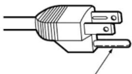
Do not remove
Pursuant to at the directive 2004/108/EC, article 9(2)
Panasonic Testing Centre
Panasonic Service Europe, a division of Panasonic Marketing Europe GmbH
Winsbergring 15, 22525 Hamburg, F.R. Germany
NOTICE:
This product has a High Intensity Discharge (HID) lamp that contains mercury. Dispase may be regulated in your community due to environmental considerations. For disposal or recycling information, please contact your local authorities, or the Electronics Industries Alliance: http://www.eiae.org
WARNING:
This equipment has been tested and found to comply with the limits for a Class B digital device, pursuant to Part 15 of the FCC Rules. These limits are designed to provide reasonable protection against harmful interference in a residential installation. This equipment generates, uses and can radiate radio frequency energy and, if not installed and used in accordance with the instructions, may cause harmful interference to radio communications. However, there is no guarantee that interference will not occur in a particular installation. If this equipment does cause harmful interference to radio or television reception, which can be determined by turning the equipment off and on, the user is encouraged to try to correct the interference by one or more of the following measures:
- Reorient or relocate the receiving antenna.
- Increase the separation between the equipment and receiver.
- Connect the equipment into an outlet on a circuit different from that to which the receiver is connected.
- Consult the dealer or an experienced radio/TV technician for help.
FCC CAUTION: To assure continued compliance, use only shielded interface cables when connecting to computers or peripheral devices. Any unauthorized changes or modifications to this equipment will void the users authority to operate.
If you use serial port to connect PC for external control of projector, you must use optional RS-232C serial interface cable with ferrite core. Any unauthorized changes or modifications to this equipment will void the user's authority to operate.
FCC RF Exposure Warning: (if provided with wireless device)
This equipment complied with FCC radiation exposure limits set forth for an uncontrolled environment.
- This equipment has been approved for mobile operation and requires minimum 20 cm spacing be provided between antenna(s) and all person's body (excluding extremities of hands, wrist and feet) during wireless modes of operation.
- This equipment may not be used with other installed transmitters, which may be capable of simultaneous transmission.
WARNING:
- Not for use in a computer room as defined in the Standard for the Protection of Electronic Computer/Data Processing Equipment, ANSI/NFPA 75.
- For permanently connected equipment, a readily accessible disconnect device shall be incorporated in the building installation wiring.
- For pluggable equipment, the socket-outlet shall be installed near the equipment and shall be easily accessible.
Declaration of Conformity
Model Number: PT-FW100NTU
Trade Name: Panasonic
Responsible party: Panasonic Corporation of North America
Address: One Panasonic Way, Secaucus, New Jersey 07094
Telephone number: (888) 411 - 1996
E-mail: projectorsupport@us.panasonic.com
This device complies with Part 15 of the FCC Rules. Operation is subject to the following two conditions: (1) This device may not cause harmful interference, and (2) this device must accept any interference received, including interference that may cause undesired operation.
Information on Disposal in other Countries outside the European
This symbol is only valid in the European Union.
If you wish to discard this product, please contact your local authorities or dealer and ask for the correct method of disposal.
Contents

Quick steps
- Set up your projector See "Setting up" on page 14.

- Connect with other devices See "Connections" on page 18.

- Prepare the Remote control See "Remote control" on page 11.

- Start projecting See "Switching the projector on/off" on page 20.

-
Adjust the image See "Menu Navigation" on page 27.
-
When you start the projection for the first time, the minimum required setting screen for projection will be displayed. See "Minimum required setting screen" on page 10.
Important Information
Important Safety Notice 2
Precautions with regard to safety. 6
WARNING 6
CAUTIONS. 7
Cautions when transporting 8
Cautions when installing 8
Cautions on use 9
Accessories 9
Preparation
Read this first 10
Minimum required setting screen. 10
About Your Projector 11
Remote control. 11
Projector body. 12
Getting Started
Setting up. 14
Screen size and throw distance 14
Projection method 15
Front leg adjusters and throwing angle. 15
Lens shift and positioning. 16
Connections 18
Before connection to the projector 18
Connecting with computers 18
Connecting with AV equipment 19
Basic Operation
Switching the projector on/off 20
Power cord. 20
POWER indicator. 20
Switching on the projector. 21
Switching off the projector. 21
Projecting an image 22
Selecting the input signal 22
Positioning the image 22
Remote control operation. 23
Operating range 23
Setting up the image position automatically. 23
Switching the input signal. 24
Using the laser pointer 24
Capturing an image 25
Stopping the projection temporary 25
Resetting to the factory default settings. 25
Projecting an image in INDEX-WINDOW mode. 25
Projecting 2 images at a time. 26
Enlarging the centred area. 26
Controlling the volume of the speaker. 26
Settings
Menu Navigation 27
Navigating through the MENU 27
Main menu and Sub-menu 28
PICTURE menu. 30
PICTURE MODE 30
CONTRAST 30
BRIGHTNESS 30
COLOR 30
TINT 30
SHARPNESS 30
COLOR TEMPERATURE 30
DAYLIGHT VIEW 30
DETAILED SETUP 31
POSITION menu 32
KEYSTONE 32
POSITION 32
DOT CLOCK 32
CLOCK PHASE 32
ASPECT 32
FRAME LOCK 33
OPTION menu. 34
INPUT GUIDE 34
STARTUPLOGO 34
COMPUTER2 SELECT 34
FILTER SETUP 34
FILTER REMAINING 34
LAMP RUNTIME 35
POWER OFF TIMER 35
DIRECT POWER ON. 35
CONTROL PANEL 35
AUTOSETUP 35
SIGNAL SEARCH 35
INSTALLATION 35
SCREEN FORMAT 35
HIGHLAND 36
TEST PATTERN. 36
DETAILED SETUP 36
SECURITY menu 37
INPUT PASSWORD 37
password CHANGE 37
TEXT DISPLAY 37
TEXT CHANGE 37
NETWORK menu 38
Items in NETWORK menu. 38
Maintenance
TEMP, LAMP and FILTER Indicators. 39
Managing the indicated problems 39
Care and Replacement 40
Cleaning the projector. 40
Replacing the ARF (Auto Rolling Filter) 40
Replacing the Lamp unit 41
Ceiling mount bracket safeguards 42
Troubleshooting. 43
Appendix
Technical Information 44
List of compatible signals 44
Serial terminal 45
Computer connection guidance 46
REMOTE terminal 47
Specifications 48
Screen size and throw distance for 16:9 aspect ratio....50
Screen size and throw distance for 4:3 aspect ratio....50
Dimensions. 51
Trademark acknowledgements 51
Index 52
Precautions with regard to safety
WARNING
If you notice smoke, strange smells or noise coming from the projector, disconnect the power plug from the wall outlet.
- Do not continue to use the projector in such cases, otherwise fire or electric shocks could result.
- Check that no more smoke is coming out, and then contact an Authorized Service Center for repairs.
- Do not attempt to repair the projector yourself, as this can be dangerous.
Do not install this projector in a place which is not strong enough to take the full weight of the projector.
- If the installation location is not strong enough, it may fall down or tip over, and severe injury or damage could result.
Installation work (such as ceiling suspension) should only be carried out by a qualified technician.
- If installation is not carried out correctly, there is the danger that injury or electric shocks may occur.
- Do not use other than an authorized ceiling mount bracket.
If foreign objects or water get inside the projector, or if the projector is dropped or the cabinet is broken, disconnect the power plug from the wall outlet.
- Continued use of the projector in this condition may result in fire or electric shocks.
- Contact an Authorized Service Center for repairs.
Do not overload the wall outlet.
- If the power supply is overloaded (for example, by using too many adapters), overheating may occur and fire may result.
Never attempt to modify or disassemble the projector.
- High voltages can cause fire or electric shocks.
- For any inspection, adjustment and repair work, please contact an Authorized Service Center.
Clean the power plug regularly to prevent it from becoming covered in dust.
- If dust builds up on the power plug, the resulting humidity can damage the insulation, which could result in fire. Pull the power plug out from the wall outlet and wipe it with a dry cloth.
- If not using the projector for an extended period of time, pull the power plug out from the wall outlet.
Do not handle the power plug with wet hands.
- Failure to observe this may result in electric shocks.
Insert the power plug securely into the wall outlet.
- If the plug is not inserted correctly, electric shocks or overheating could result.
- Do not use plugs which are damaged or wall outlets which are coming loose from the wall.
Do not place the projector on top of surfaces which are unstable.
- If the projector is placed on top of a surface which is sloped or unstable, it may fall down or tip over, and injury or damage could result.
Do not place the projector into water or let it become wet.
- Failure to observe this may result in fire or electric shocks.
Do not do anything that might damage the power cord or the power plug.
- Do not damage the power cord, make any modifications to it, place it near any hot objects, bend it excessively, twist it, pull it, place heavy objects on top of it or wrap it into a bundle.
- If the power cord is used while damaged, electric shocks, short-circuits or fire may result.
- Ask an Authorized Service Center to carry out any repairs to the power cord that might be necessary.
Do not place the projector on soft materials such as carpets or sponge mats.
- Doing so may cause the projector to overheat, which can cause burns, fire or damage to the projector.
Do not place liquid containers on top of the projector.
- If water spills onto the projector or gets inside it, fire or electric shocks could result.
- If any water gets inside the projector, contact an Authorized Service Center.
Do not insert any foreign objects into the projector.
- Do not insert any metal objects or flammable objects into the projector or drop them onto the projector, as doing so can result in fire or electric shocks.
Do not allow the + and - terminals of the batteries to come into contact with metallic objects such as necklaces or hairpins.
- Failure to observe this may cause the batteries to leak, overheat, explode or catch fire.
- Store the batteries in a plastic bag and keep them away from metallic objects.
Do not touch the leaked liquid from the batteries.
- If you touch the leaked liquid, it may hurt your skin. Immediately wash away the liquid with water and seek medical advice.
- If you get the leaked liquid in your eye, it may cause blindness or damage. Never rub your eye, and immediately wash away the liquid with water and seek medical advice.
During a thunderstorm, do not touch the projector or the cable.
Electric shocks can result.
Do not use the projector in a bath or shower.
- Fire or electric shocks can result.
Do not place your skin into the light beam while the projector is being used.
- Strong light is emitted from the projector's lens. If you place directly into this light, it can hurt or damage your skin.
Do not look into the lens while the projector is being used.
- Strong light is emitted from the projector's lens. If you look directly into this light, it can hurt and damage your eyes.
- Be especially careful not to let young children look into the lens. In addition, turn off the power and disconnect the power plug when you are away from the projector.
Do not place your hands or other objects close to the air outlet port.
- Heated air comes out of the air outlet port. Do not place your hands or face, or objects which cannot withstand heat close to this port [allow at least 50~cm (20") of space], otherwise burns or damage could result.
Replacement of the lamp is recommended to be carried out by a qualified technician.
The lamp has high internal pressure. If improperly handled, explosion might result.
- The lamp can easily become damaged if struck against hard objects or dropped, and injury or malfunctions may result.
When replacing the lamp, allow it to cool for at least one hour before handling it.
The lamp cover gets very hot, and touching it can cause burns.
Before replacing the lamp, be sure to disconnect the power plug from the wall outlet.
Electric shocks or explosions can result if this is not done.
Do not allow infants or pets to touch the remote control unit.
- Keep the remote control unit out of the reach of infants and pets after using it.
CAUTIONS
Do not cover the air inlet port or the air outlet port.
- Doing so may cause the projector to overheat, which can cause fire or damage to the projector.
- Do not place the projector in narrow, badly ventilated places such as closets or bookshelves.
- Do not place the projector on cloth or papers, as these materials could be drawn into the air inlet port.
Do not set up the projector in humid or dusty places or in places where the projector may come into contact with oily smoke or steam.
- Using the projector under such conditions may result in fire, electric shocks or plastic deterioration. The plastic deterioration may cause the falling down of the projector which is mounted in the ceiling.
Do not set up the projector in a high temperature environment, such as near a heater or in direct sunlight.
- Failure to observe this may result in fire, malfunction or plastic deterioration.
Do not set up the projector outdoors.
- The projector is designed for indoor use only.
When disconnecting the power cord, hold the plug, not the cord.
- If the power cord itself is pulled, the cord will become damaged, and fire, short-circuits or serious electric shocks may result.
Always disconnect all cables before moving the projector.
- Moving the projector with cables still attached can damage the cables, which could cause fire or electric shocks to occur.
Do not place any heavy objects on top of the projector.
- Failure to observe this may cause the projector to become unbalanced and fall, which could result in damage or injury.
Do not short-circuit, heat or disassemble the batteries or place them into water or fire.
- Failure to observe this may cause the batteries to overheat, leak, explode or catch fire, and burns or other injury may result.
When inserting the batteries, make sure the polarities (+ and -) are correct.
- If the batteries are inserted incorrectly, they may explode or leak, and fire, injury or contamination of the battery compartment and surrounding area may result.
Use only the specified batteries.
- If incorrect or different kind of batteries are used, they may explode or leak, and fire, injury or contamination of the battery compartment and surrounding area may result.
Do not mix old and new batteries.
- If the batteries are inserted incorrectly, they may explode or leak, and fire, injury or contamination of the battery compartment and surrounding area may result.
Remove the used batteries from the remote control promptly.
- If you leave used batteries in the remote control for an extended period of time, it may cause liquid leaking, abnormal internal temperature rising or explosion.
If not using the projector for an extended period of time, disconnect the power plug from the wall outlet and remove the batteries from the remote control.
- If dust builds up on the power plug, the resulting humidity may damage the insulation, which could result in fire.
- ● Keeping or leaving the remote control with batteries inside may cause insulation deterioration, electrical leakage or explosion which could result in fire.
Do not put your weight on this projector.
- You could fall or the projector could break, and injury may result.
- Be especially careful not to let young children stand or sit on the projector.
Disconnect the power plug from the wall outlet as a safety precaution before carrying out any cleaning.
Electric shocks can result if this is not done.
If the lamp has broken, ventilate the room immediately. Do not touch or bring your face close to the broken pieces.
- Failure to observe this may cause the user to absorb the gas which was released when the lamp broke and which contains nearly the same amount of mercury as fluorescent lamps, and the broken pieces may cause injury.
- If you believe that you have absorbed the gas or that the gas has got into your eyes or mouth, seek medical advice immediately.
- Ask your dealer about the replacement of the lamp unit and check the inside of the projector.
Ask an Authorized Service Center to clean inside the projector at least once a year.
- If dust is left to build up inside the projector without being cleaned out, it can result in fire or problems with operation.
- It is a good idea to clean the inside of the projector before the season for humid weather arrives. Ask your nearest Authorized Service Center to clean the projector when required. Please discuss with the Authorized Service Center regarding cleaning costs.
We are constantly making efforts to preserve and maintain a clean environment. Please take non repairable units back to your dealer or a recycling company.
Cautions when transporting
Do not subject the projector to excessive vibration or shocks.
- The projector lens need to be handled with care.
- Cover the lens with the lens cover when transporting the projector.
When transporting the projector, hold the body at the bottom securely.
- Do not hold the adjuster legs or the top cover to move the projector, as this may damage the projector.
Cautions when installing
Avoid setting up in places which are subject to vibration or shocks.
- The internal parts can be damaged, which may cause malfunctions or accidents.
Avoid setting up in places which are subject to sudden temperature changes, such as near an air conditioner or lighting equipment.
- The life of the lamp may be shortened or the projector may be turned off. See "TEMP indicator" on page 39.
Do not set up the projector near high-voltage power lines or near motors.
- The projector may be subject to electromagnetic interference.
If installing the projector to the ceiling, ask a qualified technician to carry out all installation work.
- You will need to purchase the separate installation kit (Model No. ET-PKF100H, ET-PKF100S). Furthermore, all installation work is should only be carried out by a qualified technician.
See "Ceiling mount bracket safeguards" on page 42 for the Safety cable installation.
If using this projector at high elevations (above 1400 m), set the HIGHLAND to ON. See "HIGHLAND" on page 36.
- Failure to observe this may result in malfunctions or the life of the lamp or the other components may be shortened.
Cautions on use
In order to get the best picture quality
- Draw curtains or blinds over any windows and turn off any lights near the screen to prevent outside light or light from indoor lamps from shining onto the screen.
Do not touch the surfaces of the lens or the front glass with your bare hands.
- If the surface of the lens becomes dirty from fingerprints or anything else, this will be magnified and projected onto the screen. Moreover, when not using the projector, close the Front panel cover.
Liquid crystal panel
- Do not project the same image for long periods of time, as this may remain as an afterimage on the liquid crystal panel.
- The liquid crystal panel of the projector is built with very high precision technology to provide fine picture details. Occasionally, a few stuck pixels may appear on the screen as fixed points of blue, green or red. It is recommended to switch off the projector once and try after 1 hour later again. Please note that this does not affect the performance of your LCD.
The projector has a high pressure mercury lamp and that is characterized as follows.
The brightness of the lamp depends on the duration of use.
- The lamp may explode or shorten the lamp life by shocks or chipping damage.
- The lamp may explode only occasionally after using the projector.
- The lamp may explode if using the projector after the instructed lamp replacement timing.
- The lamp life is depends on individual lamp characteristics, usage condition and the installation environment. Especially the consecutive use of the projector for more than 10 hours, or the frequent switching on or off may greatly affect on the lamp life.
Screen
- Do not apply any volatile substances which may cause discoloration to the screen, and do not let it become dirty or damaged.
Optical components
- If you use the projector consecutively 6 hours every day, the optical components may need to be replaced in less than 1 year.
Accessories
Make sure the following accessories are provided with your projector.
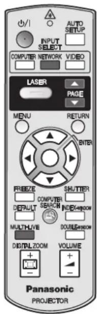
Remote control for PT-FW100NTU (x1) N2QAYB000158
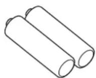
AA batteries for Remote control (x2)
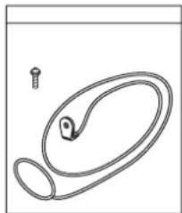
Safety cable
TTRA0141
Attachment screw (x1)
Safety cable (x1)
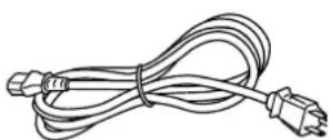
Power cord (x1) K2CM3DH00015

CD-ROM (x1) TQBH9009
Read this first
Minimum required setting screen
When you start the projection for the first time, the minimum required setting screen for projection will be displayed.
LANGUAGE
Select the required language setting.
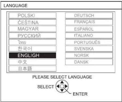
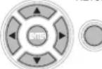
Press buttons of the Remote control or Control panel on the projector to highlight the required language, and press ENTER to proceed to the next setting.
OPTION
Select the current projection method, screen size and fan speed setting. If you need return to the previous setting, press the RETURNN button.
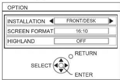
INSTALLATION
Press buttons of the Remote control or Control panel on the projector to select the required installation method. Press to proceed to the HIGHLAND setting.
| FRONT/DESK | Setting on a desk/floor and projecting from front |
| FRONT/CEILING | Mounting in the ceiling and projecting from front |
| REAR/DESK | Setting on a desk/floor and projecting from rear |
| REAR/CEILING | Mounting in the ceiling and projecting from rear |
SCREEN FORMAT
Select the required screen format by pressing
- 16:10 When project on a 16:10 or 4:3 screen.
- 16:9 When project on a 16:9 screen.
HIGHLIGHT
If you use the projector at high elevation, the HIGHLAND setting need to be ON to set the fan speed high. Press to select the required option. If you need to return to the INSTALLATION, press .
OFF The fan speed is low.
- ON The fan speed is high.
NOTE:
- At 1400 m (4593 ft) above sea level, the setting must be ON.
- The loudness of fan noise depends on the HIGHLAND setting.
Press the ENTER button to start the projection.
- Once you finish the minimum requirement setting, it will not be displayed again unless the projector is initialized. See "INITIALIZE ALL" on page 36.
- You can change the settings from the MAIN MENU. See "Menu Navigation" on page 27.
About Your Projector
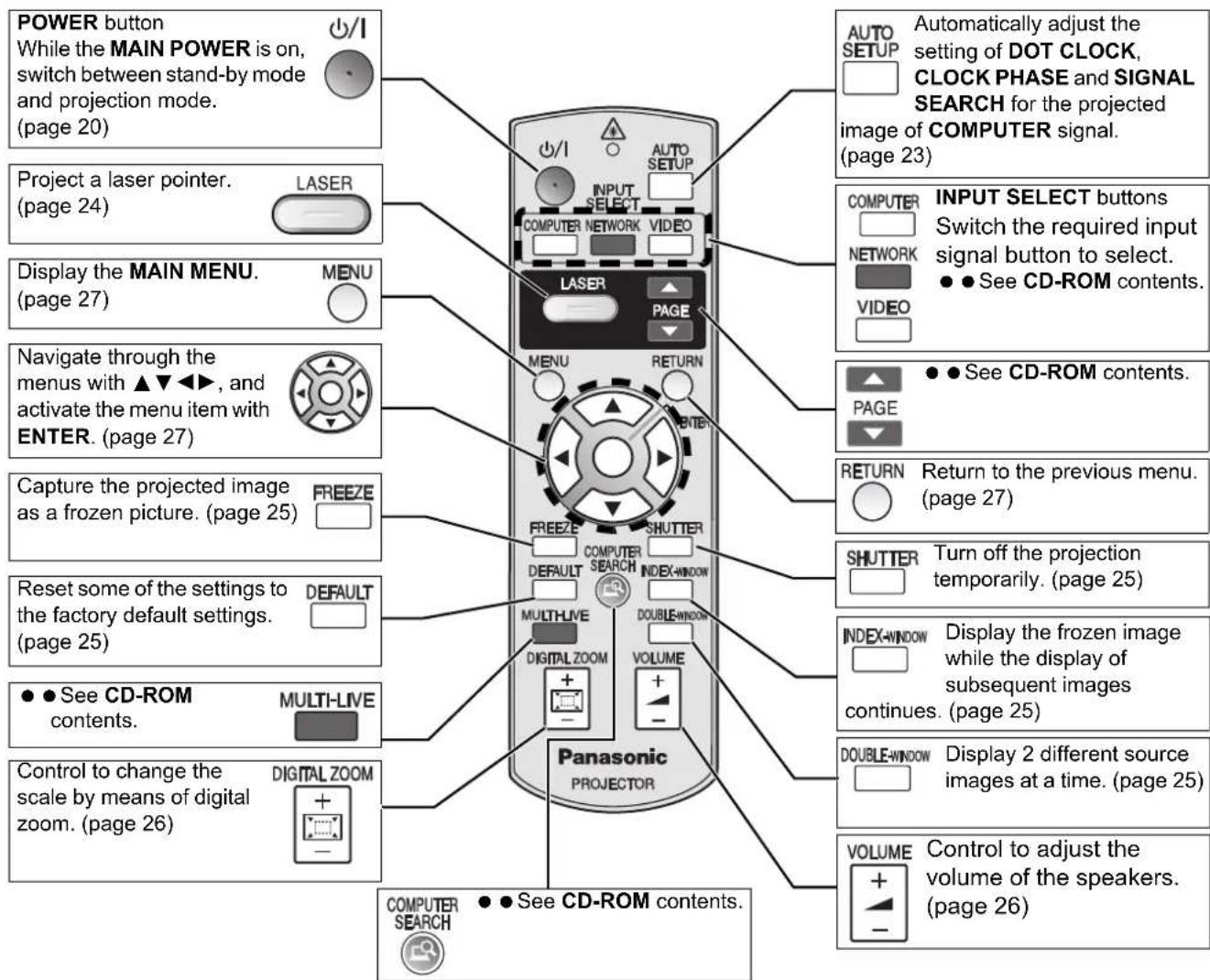
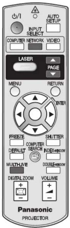
Remote control
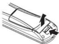
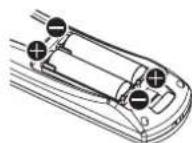
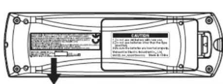
Battery compartment
- Press the tab and lift up the cover.
- Insert the batteries according to the polarity diagram indicated inside.
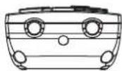
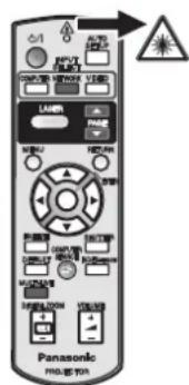
Top view
Remote control signal and Laser pointer beam emitters. (page 23)
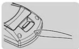
Attaching a hand strap
You can attach a favorite strap on to the Remote control.
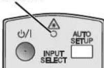
Remote control indicator
If you press any button except the LASER button, the Remote control indicator will flash. If you press the LASER button, it will lit.
Remote control indicator
NOTE:
- Do not drop the Remote control.
- Avoid contact with liquids or moisture.
- Use manganese batteries or alkaline batteries with the Remote control.
- Do not attempt to modify or disassemble the Remote control. Contact an Authorized Service Center for repairs.
- Do not keep pressing the Remote control buttons as this may shorten battery life.
- Do not point the laser in other people's eyes or stare into beam.
See "Remote control operation" on page 23.
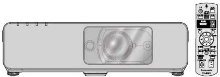
Projector body
Top and front view
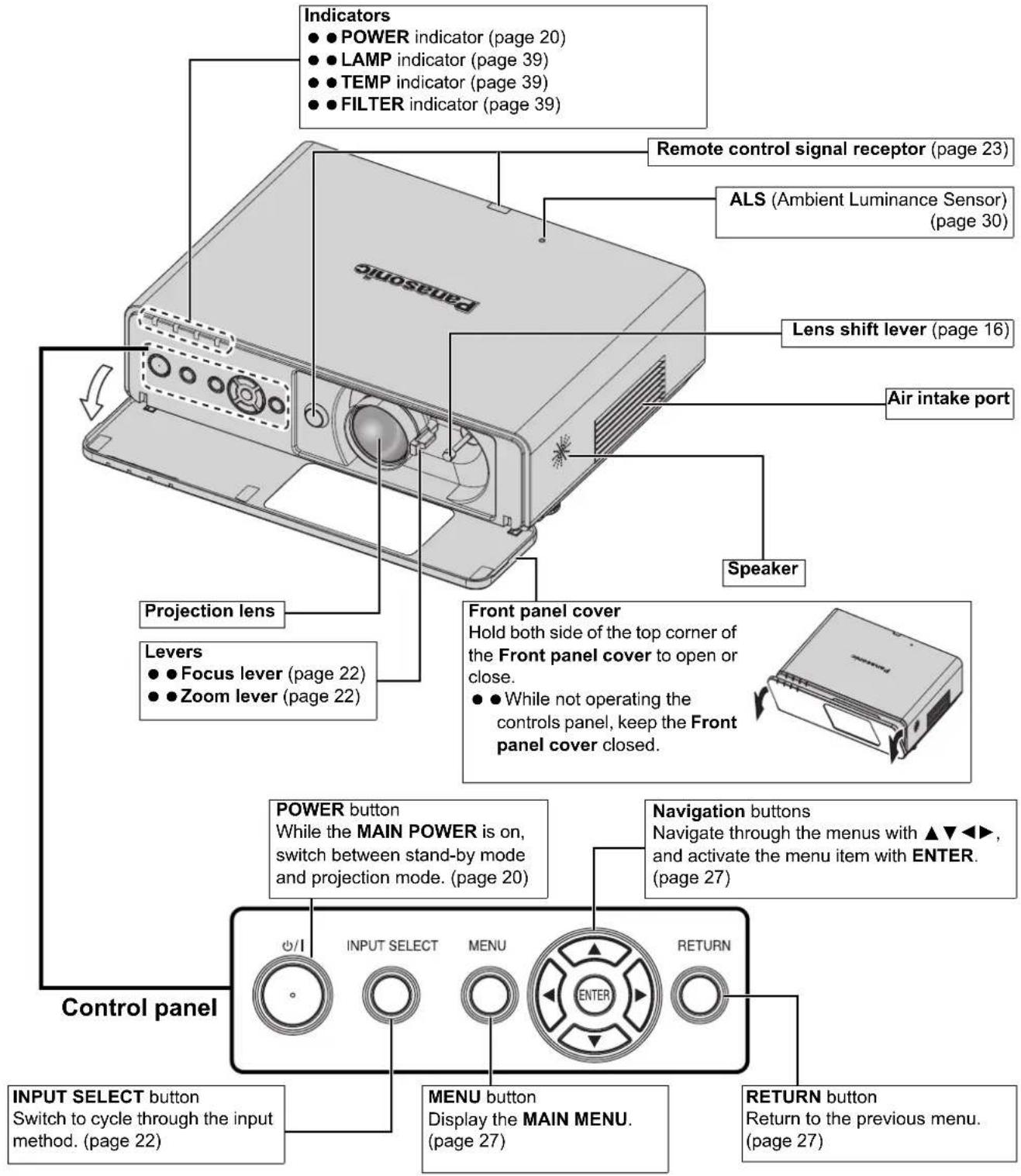
NOTE:
- Do not cover the ventilation openings or place anything within 50~cm (20") of them as this may cause damage or injury.
- While the projector is not in use, keep the FRONT PANEL COVER closed to protect the lens.
Back and bottom view
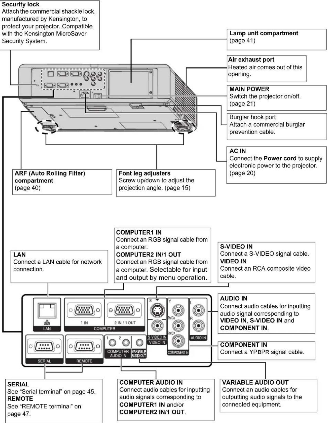
NOTE:
- Do not cover the ventilation openings or place anything within 50~cm (20") of them as this may cause damage or injury.
- When a cable is connected to the VARIABLE AUDIO OUT, the built-in speaker will be disabled.
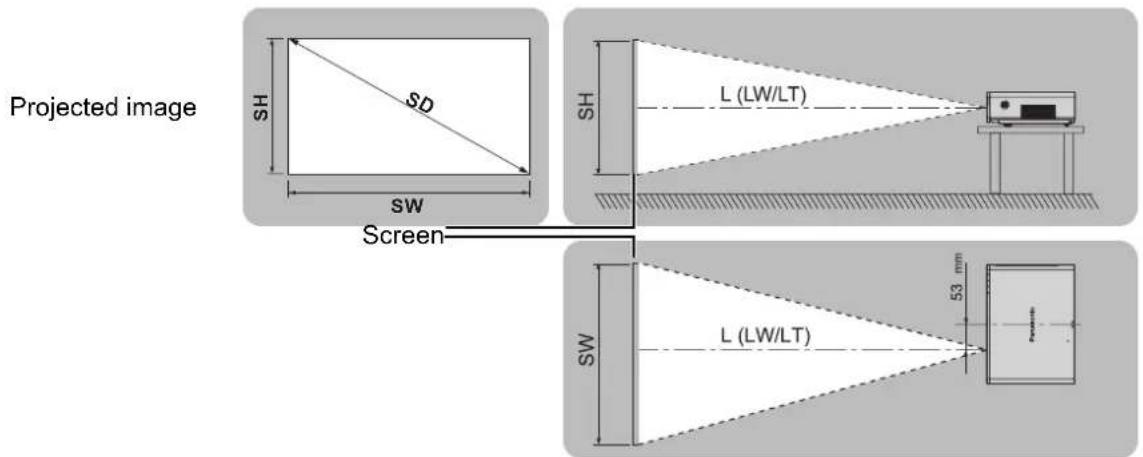
Screen size and throw distance
You can adjust the projection size with 2.0x zoom lens. Calculate and define the throw distance as follows.
| Projection size (16 : 10) Throw distance (L) | ||||
| Screen Diagonal (SD) | Screen height (SH) | Screen width (SW) | Minimum distance (LW) | Maximum distance (LT) |
| (0.84 m) 33" 0.44 m | (1'5") 0.71 m (2'3") 1.8 | m (5'10") | ||
| (1.02 m) 40" 0.54 m | (1'9") 0.86 m (2'9") 1.1 | m (3'7") 2.3 m (7'6") | ||
| (1.27 m) 50" 0.67 m | (2'2") 1.08 m (3'6") 1.4 | m (4'7") 2.8 m (9'2") | ||
| (1.52 m) 60" 0.81 m | (2'7") 1.29 m (4'2") 1.7 | m (5'6") 3.4 m (11'1") | ||
| (1.78 m) 70" 0.94 m | (3'1") 1.51 m (4'11") 2.0 | m (6'6") 4.0 m (13'1") | ||
| (2.03 m) 80" 1.08 m | (3'6") 1.72 m (5'7") 2.3 | m (7'6") 4.6 m (15'1") | ||
| (2.29 m) 90" | 1.21 m (3'11") | 1.94 m (6'4") | 2.6 m (8'6") | 5.1 m (16'8") |
| (2.54 m) 100" | 1.35 m (4'5") | 2.15 m (7') | 2.9 m (9'6") | 5.7 m (18'8") |
| (3.05 m) 120" | 1.62 m (5'3") | 2.58 m (8'5") | 3.4 m (11'1") | 6.9 m (22'7") |
| (3.81 m) 150" | 2.02 m (6'7") | 3.23 m (10'7") | 4.3 m (14'1") | 8.6 m (28'2") |
| (5.08 m) 200" | 2.69 m (8'9") | 4.31 m (14'1") | 5.7 m (18'8") | 11.5 m (37'8") |
| (6.35 m) 250" | 3.37 m (11") | 5.38 m (17'7") | 7.2 m (23'7") | 14.3 m (46'10") |
| (7.62 m) 300" | 4.04 m (13'3") | 6.46 m (21'2") | 8.6 m (28'2") | 17.2 m (56'5") |
- All measurements above are approximate and may differ slightly from the actual measurements.
Calculation methods for screen dimensions
You can calculate more detailed screen dimension from the screen diagonal.
$$ \begin{array}{l} \mathrm {S W} (\mathrm {m}) = \mathrm {S D} (^ {\prime \prime}) \times 0. 0 2 1 5 \mathrm {S H} (\mathrm {m}) = \mathrm {S D} (^ {\prime \prime}) \times 0. 0 1 3 5 \ L W (m) = 0. 0 2 8 9 \times S D \left("\right) - 0. 0 4 6 L T (m) = 0. 0 5 7 6 \times S D \left("\right) - 0. 0 6 1 \ \end{array} $$
- The results above are approximate and may differ slightly from the actual measurements.
NOTE:
See page 50 for the screen size and throw distance of 4:3/16:9.
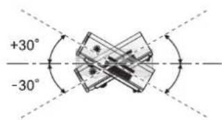
- Do not use the projector at a raised or a horizontally tilted position as it may cause malfunction of the projector.
- Make sure the projector lens surface is parallel with the screen. You can tilt the projector body approximately ± 30^ vertically. Overtilting may result in shortening the component's life.
- For the best quality of the projection image, install a screen where sun light or room light does not shine directly onto the screen. Close window shades or curtains to block the lights.
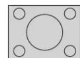
Projection method
You can use the projector with any of the following 4 projection methods. To set the desired method in the projector, See "INSTALLATION" on page 35.
Setting on a desk/floor and projecting from front
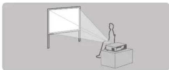
INSTALLATION:FRONT/DESK
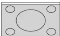
Setting on a desk/floor and projecting from rear
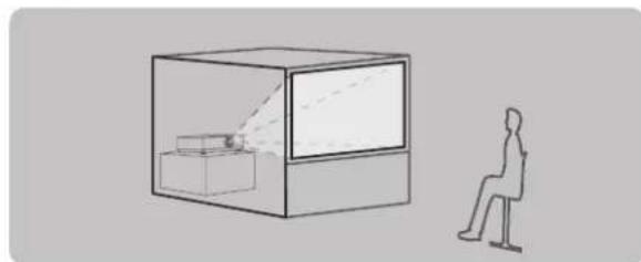
INSTALLATION: REAR/DESK
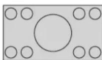
Mounting in the ceiling and projecting from front
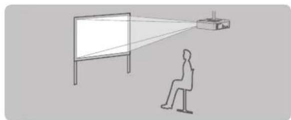
INSTALLATION:FRONT/CEILING
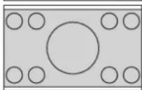
Mounting in the ceiling and projecting from rear
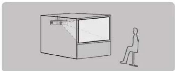
INSTALLATION: REAR/CEILING
NOTE:
- A translucent screen is required for rear projection.
- When mounting the projector in the ceiling, the optional ceiling mount bracket (ET-PKF100H, ET-PKF100S) is required.
See "Ceiling mount bracket safeguards" on page 42.
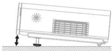
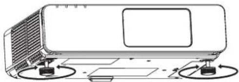
Front leg adjusters and throwing angle
You can screw up/down the front leg adjusters to control the angle of the projector for adjusting the throwing angle. See "Positioning the image" on page 22.
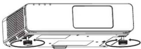
NOTE:
- Heated air comes out of the Air exhaust port. Do not touch the Air exhaust port directly.
- If keystone distortion occurs, see "KEYSTONE" on page 32.
- Screw up the adjuster legs, and an audible click will be heard as the limit.
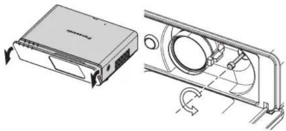
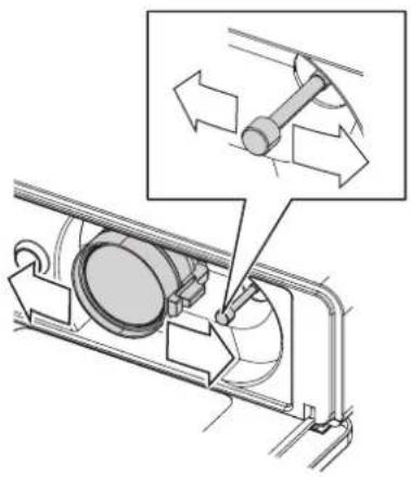
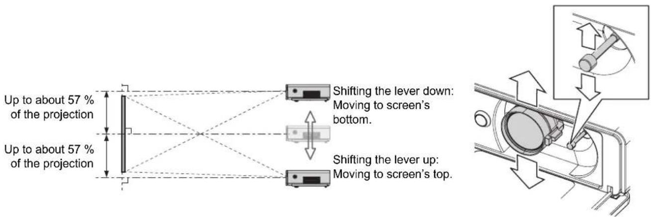
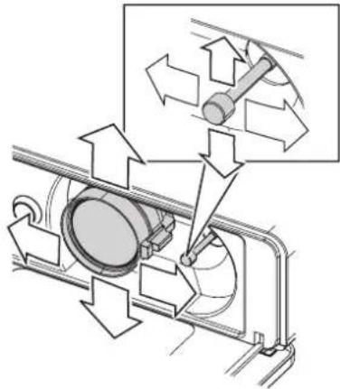
Lens shift and positioning
If the projector is not positioned right in front of the center of the screen, you can adjust the projected image position by moving the Lens shift lever within the shift range of the lens.

Adjusting the Lens shift lever
- Open the Front panel cover.
- Screw the Lens shift lever counterclockwise to unlock.
- Move the Lens shift lever to adjust the projected image position.
- Screw the Lens shift lever clockwise to lock.

Horizontal shift
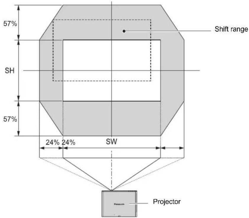
You can place the projector where the projector lens is up to 24% horizontally off-center from the screen and then adjust the image position with the Lens shift lever.
Up to about 24% of the projection
Up to about 24% of the projection
Shifting the lever right: Moving to screen's right.
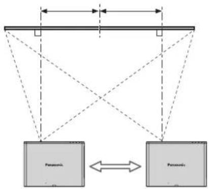
Shifting the lever left: Moving to screen's left.

Vertical shift
You can place the projector where the projector lens is up to 57% vertically off-center from the screen and the adjust the image position with the Lens shift lever.
Projectile location range
You can determine where to locate the screen and the projector by considering the lens shift possibilities. See "Positioning the image" on page 22.
- When the screen position is fixed
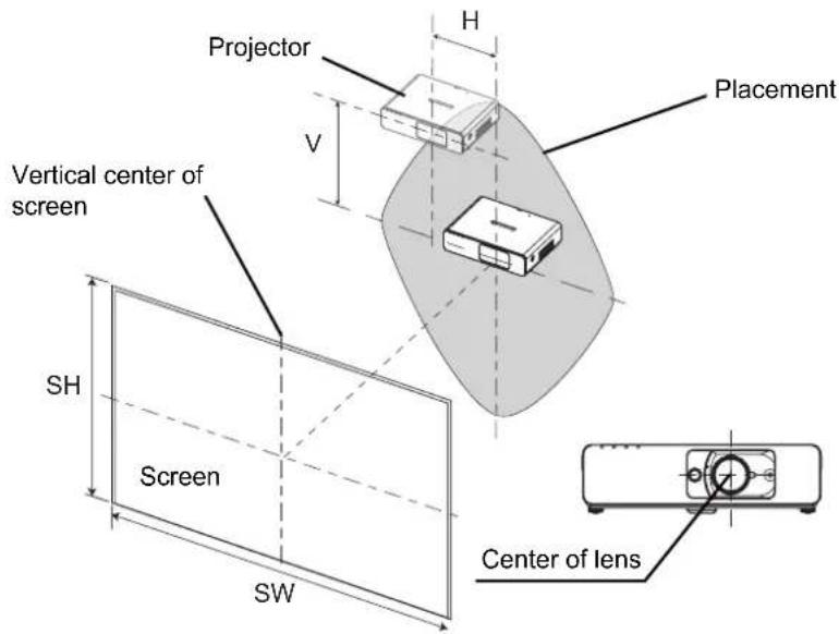
- When the projector position is fixed
NOTE:
- When the projector is located right in front of the screen and the Lens shift lever is centred, you will get the best quality of the projection image.
- When the Lens shift lever is at the vertical limit of the shift range, you cannot move the lever to the horizontal limit, likewise when the Lens shift lever is at the horizontal limit of the shift range, you cannot move the lever to the horizontal limit.
- When the projector is tilted and you adjust KEYSTONE, the center of the screen and the lens need to be realigned.
- Do not attempt to pull the Lens shift lever hard while adjusting.
Connections
Before connection to the projector
- Read and follow the operating and connecting instructions of each peripheral device.
- The peripheral devices must be turned off.
- Use cables that match each peripheral device to be connected.
- If the input signal is affected by signal jitter, the projected image may have poor image quality and timebase correction is effective.
- Confirm the type of video signals. See "List of compatible signals" on page 44.
Connecting with computers
Computers Monitor
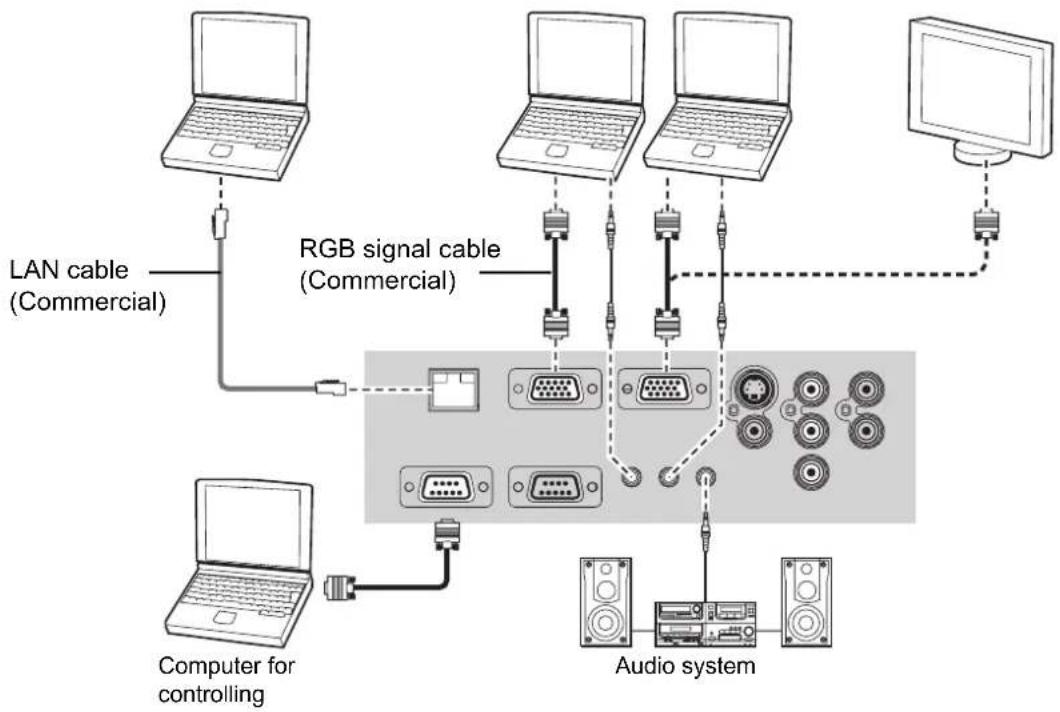
NOTE:
- When COMPUTER2 SELECT in the OPTION menu is set to OUTPUT, do not connect any input signals.
- See CD-ROM contents for the LAN network connection.
- LAN terminal
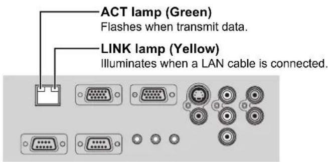
NOTE:
- Do not touch the metal parts of the LAN terminal. Failure to observe this may cause malfunction by static electricity.
Connecting with AV equipment
Connecting with VIDEO IN/S-VIDEO IN
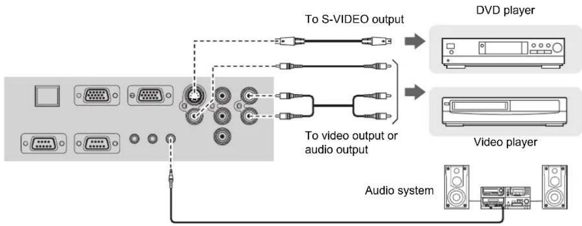
NOTE:
- When you connect more than one AV equipment, switch the audio connection manually.
Connecting with COMPONENT IN
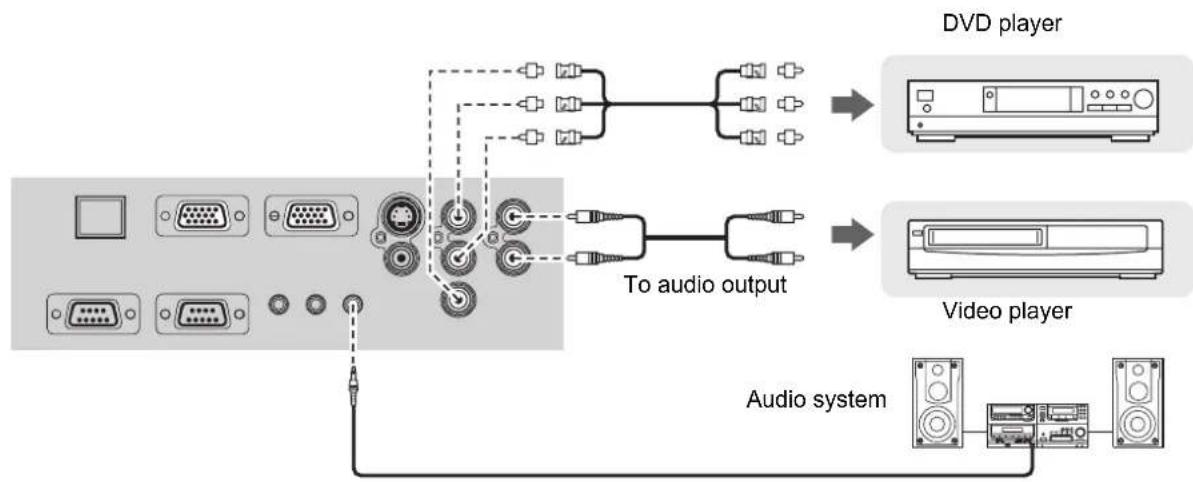
NOTE:
- If you connect the BNC cables, use with a commercial BNC-RCA adaptor.
Switching the projector on/off
Power cord
Connecting
- Make sure the shape of the power plug and the AC IN connector on the back of the projector match, then push the plug all the v
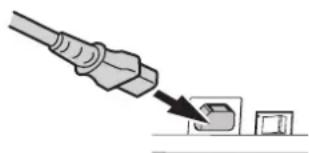
- Connect the Power cord to a wall outlet.
Disconnecting
- Make sure the MAIN POWER is switched off and unplug the Power cord from the wall outlet.
- Hold the plug and unplug the Power cord from the AC IN connector on the back of the projector.
Direct power off function
You can disconnect the Power cord from the projector or switch off the MAIN POWER button while projecting or soon after projecting. The internal lamp cooling fan will keep operating by the internal power supply.
NOTE:
- If the projector is switched on again while the internal cooling fan is still operating by the internal power supply, it may take a while to start the projection.
Direct power on function
If you activate the DIRECT POWER ON, you can start the projection only with connecting the Power cord or switching on the MAIN POWER. See "DIRECT POWER ON" on page 35.
NOTE:
- Do not use other than a provided Power cord.
- Ensure all the input devices are connected and turned off before connecting the Power cord.
- Do not force the connector as this may damage the projector and/or the power cord.
- Dirt or dust build-up around plugs may cause fire or electrical hazards.
- Switch off the power to the projector when not in use.
POWER indicator
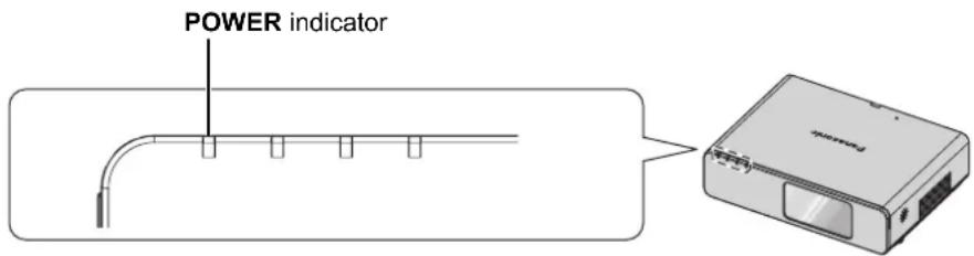
| Indicator status Status | ||
| No illumination or flashing | The MAIN POWER is switched off. | |
| RED | Lit | The MAIN POWER is switched on and the projector is in standby. When the LAMP or TEMP indicator is flashing, the POWER indicator will not be lit. |
| Flashing | Network connection is ready while the POWER is turned off. | |
| GREEN | Flashing | The POWER is switched on and the projector is getting ready to project. |
| Lit The projector is ready to project. | ||
| ORANGE | Lit | The POWER is switched off and the projector is cooling the lamp. |
| Flashing | The POWER is switched on again when cooling the lamp and recovering to projection mode. Recovery may take a while. | |
NOTE:
- If the projector is switched on again while the internal cooling fan is still operating by the internal power supply, it may take a while to start the projection.
The electric consumption in standby mode is 4W
Switching on the projector
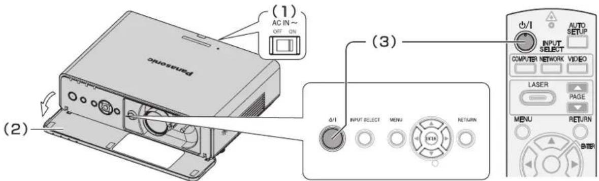
- Switch the MAIN POWER on.
The power indicator lights up in RED. -
Open the Front panel cover.
This is not necessary in Remote control operation. -
Press the POWER button.
The power indicator lights up in GREEN after flashing for a while.
- The STARTUP LOGO is displayed on the screen. See "STARTUP LOGO" on page 34.
NOTE:
- When starting up the projector some small rattling or tinkling sound may be heard, or the display may flicker for the characteristics of the lamp. Those are normal and do not affect the performance of the projector.
- If you disconnected the Power cord or switched off the MAIN POWER while on projecting mode, the projection will start with connecting the Power cord or switching on the MAIN POWER. See "DIRECT POWER ON" on page 35.
Switching off the projector
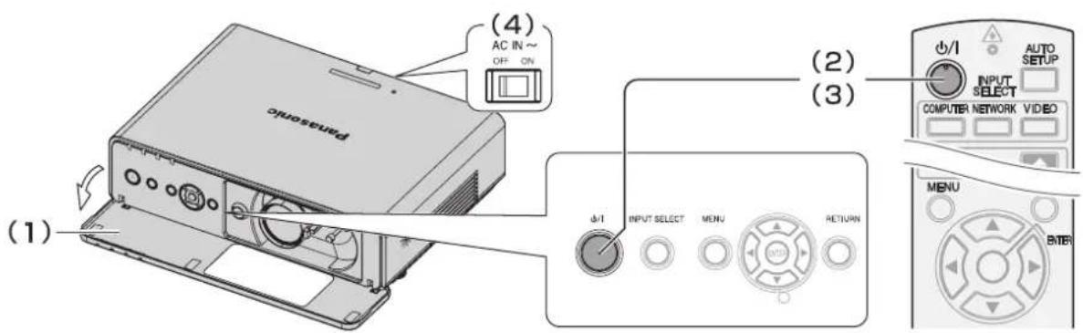
- Open the Front panel cover.
This is not necessary in Remote control operation.
- Press the POWER button.
The confirmation screen is displayed. It will disappear and return to the projection after 10 seconds without any operation.
- To return to the projection, press any button except the POWER button.
- Press the POWER button.
- The power indicator lights up in ORANGE while cooling the lamp, then illuminates RED when is ready to switch off the MAIN POWER.
- Switch off the MAIN POWER on the back of the projector.
NOTE:
- Press the POWER twice or for a long duration to switch the power off.
- You can disconnect the Power cord or switch off the MAIN POWER instead of following this procedure. See "DIRECT POWER ON" on page 35.
- You can turn off the projector by pressing the POWER button longer than 0.5 seconds.
Projecting an image
Selecting the input signal
- Switch on the connected devices.
- Press the play button of the required device.
- Press the INPUT SELECT buttons to select the required input method if needed. See "Switching the input signal" on page 24.
The image will be projected on the screen.
NOTE:
- SIGNAL SEARCH is ON as default and the signal from the connected devices is detected automatically. See "SIGNAL SEARCH" on page 35.
Positioning the image
- Open the Front panel cover.
- Adjust the projected image with the Lens shift lever. See "Lens shift and positioning" on page 16.
-
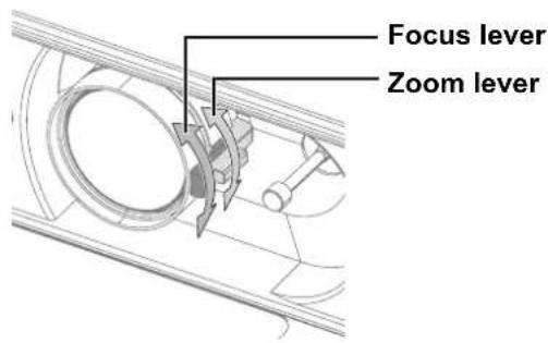
Adjust the focus and the projected image size.
-
Turn the Focus lever and Zoom lever to adjust the image.
- You can confirm the adjusted effect with the TEST PATTERN in OPTION menu. See "TEST PATTERN" on page 36.
-
Adjust the angle of the projector.
-
Screw down the Front leg adjusters and adjust the angle vertically.
See "Front leg adjusters and throwing angle" on page 15.
NOTE:
- Do not touch the Air Exhaust port as this may cause burns or injury.
- If keystone distortion occurs, see "KEYSTONE" on page 32.
- If you adjust the focus, you may need to adjust the size of the image by moving the Zoom lever again.
Remote control operation
Operating range
You can operate the projector with the Remote control within the remote range 15m (49'2").
Facing to the projector
Ensure the Remote control emitter is facing to the Remote control signal receptor on front/back of the projector and press the required buttons to operate.
Facing to the screen
Ensure the Remote control emitter is facing to the screen and press the required buttons to operate the projector. The signal will be reflected off the screen. The operating range may differ due to the screen material. This function may not be effective with a translucent screen.
NOTE:
- Do not let strong light shine onto the signal receptor. The Remote control may malfunction under strong light such as fluorescent.
- If there are any obstacles between the Remote control and the Remote control signal receptor, the Remote control may not operate correctly.
Setting up the image position automatically

You can adjust the setting of POSITION, DOT CLOCK and CLOCK PHASE in the POSITION menu automatically for the projected COMPUTER signal image.
NOTE:
- If the dot clock frequency is 108 MHz or higher, AUTO SETUP is not effective.
- If the projected image is dark or blurred around the edge, AUTO SETUP may stop the processing before complete. Project a much clearer or lighter image and press the AUTO SETUP button again.
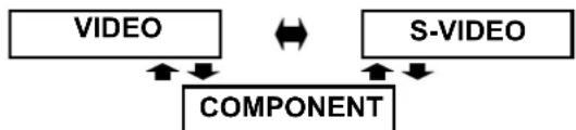
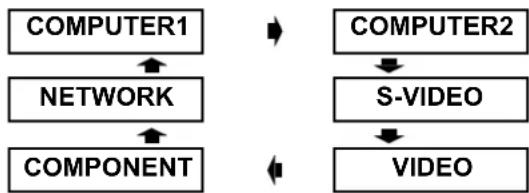
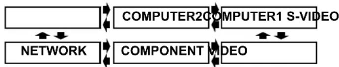
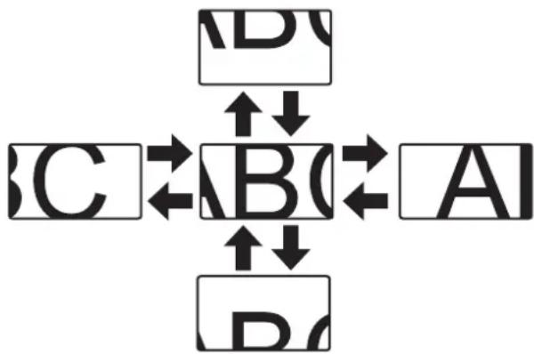
Switching the input signal

NETWORK

VIDEO
You can switch the input method manually by pressing the COMPUTER, NETWORK and VIDEO buttons. Press the required button several times or to cycle through the input methods as follows. The actual projected image will be changed in a while.
The graphical guidance will be displayed on the upper right of the projected image and you can confirm the selected input method which is highlighted in yellow. See "INPUT GUIDE" on page 34.
- Pressing the COMPUTER button
COMPUTER1

COMPUTER2
NOTE:
- Only when the COMPUTER2 SELECT is set to INPUT, you can switch between COMPUTER1 and COMPUTER2.
- Pressing the NETWORK button
See CD-ROM contents for more detailed information.
- Pressing the VIDEO button
- Pressing the INPUT SELECT button on the projector
NOTE:
- If you select an unplugged input method, the guidance will blink on and off several times.
See "List of compatible signals" on page 44.
See "Connections" on page 18.
Using the laser pointer

LASER
You can highlight items on the screen with the red laser pointer while projecting the image in presentations or visual demonstrations as an eye-catching pointing device.
Hold down the LASER button to goes on the laser pointer and release to goes off.
Top view

Laser pointer beam emitter
- Deactivating switch
NOTE:
- The laser pointer should never be projected directly into the eyes of a person or animal.
- Do not aim the laser at reflective surfaces.
- Do not allow children to use laser pointer.
- Never look directly into the laser beam.
- The laser pointer is not effective with translucent screens.
- Please read the cautions on the Remote control.
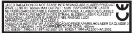
This is a Class 2 laser product.
Cautions
COMPLIANT WITH THE ENROLLMENT AND RETURN OF THE CANDIDATE.
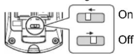
- Deactivating the LASER button
You can deactivate the LASER button for an accidental operation.
- Open the battery compartment cover of the Remote control.
- Slide the switch tab.
- Close the battery compartment cover of the Remote control.
See "Battery compartment" on page 11.
CAUTION: Use of controls of adjustments or performance of procedures other than those specified herein may result in hazardous radiation exposure.
Capturing an image

When projecting an image, press FREEZE to capture the projected image and display it on the screen as a still picture. While the image is frozen, the sound will be stopped.
Press the FREEZE button to return to the projection.
Stopping the projection temporary

You can turn off the lamp and stop the projection temporary for electrical power save.
Press the SHUTTER button to return to the projection.
Resetting to the factory default settings

You can reset most of the customized settings to the factory defaults by pressing the DEFAULT button of the Remote control. Display the required sub menu or the menu items, and press the DEFAULT button again. See "Main menu and Sub-menu" on page 28.
NOTE:
- Some menu items are not available to reset by pressing the DEFAULT button. Adjust each menu items manually.
- To reset all the settings to the factory defaults, see "INITIALIZE ALL" on page 36.
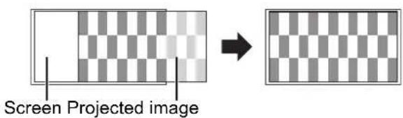
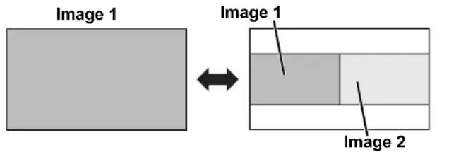
Projecting an image in INDEX-WINDOW mode
You can project an image in split 2 windows as an INDEX-WINDOW, one is frozen, stored in memory and displayed on the screen's left side, while the display of subsequent images continues on the right.
To escape from the INDEX-WINDOW, press the MENU or RETURN button.
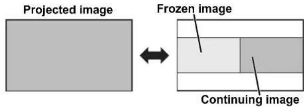
- Changing the image size
Press to switch and cycle through in 3 size.
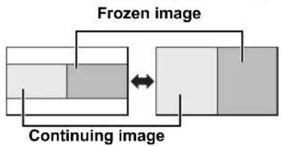
NOTE:
- If you change the window size, the aspect ratio of the image is changed and becomes vertically elongated.
- Capturing a new image
While in INDEX-WINDOW mode, press ENTER to capture a new image and the frozen image window will be updated in a while.
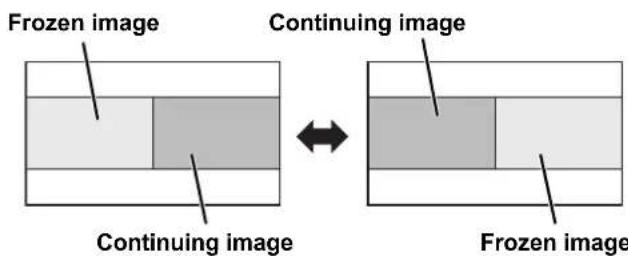
- Switching the position
In default, the frozen image is displayed on the left and the subsequent image is displayed on the right. Press to switch the position.
Projecting 2 images at a time
You can project the image and another source of image at the same time in double window style. Press any button of RETURN, MENU, DOUBLE-WINDOW or INPUT SELECT buttons to return to the normal projection style.
NOTE:
- FREEZE and VOLUME controls are available with the first image only.
- While DOUBLE-WINDOW is activated, DIGITAL ZOOM, INDEX-WINDOW and AUTO SETUP are not available.
- While DOUBLE-WINDOW is activated, the main menu will not be displayed.
The second image will apply to the value of the PICTURE settings of the first image except CONTRAST and BRIGHTNESS. - COMPUTER and NETWORK signals will not keep the adjusted aspect ratio.

- Unavailable combinations
The following combinations are not available.
- COMPUTER1 - COMPONENT
- COMPUTER2-NETWORK
S-VIDEO -VIDEO
S-VIDEO-COMPONENT
VIDEO-COMPONENT

- Switching the signal
In default, the first image is displayed on the left and the second image is displayed on the right. You can switch and cycle through the signals of the second image by pressing
Enlarging the centred area
DIGITAL ZOOM

You can enlarge the projected image down to a centred area for emphasizing within the range of 1x to 2x.
NOTE:
- When the COMPUTER signal is projected, the enlargement range will be changed to 1x to 3x. When the FRAME LOCK in POSITION menu is set to ON, the enlargement range is 1x to 2x. See "FRAME LOCK" on page 33.
- When the input signal is changed while the DIGITAL ZOOM is activated, the DIGITAL ZOOM will be cancelled.
- While DIGITAL ZOOM is activated, FREEZE is not available.

- Enlarging the image
- Press DIGITAL ZOOM +/- once.
The centred area of the image will then be enlarged to 1.5x

- Adjust the image size by pressing DIGITAL ZOOM +/-
The image size will be changed in steps of 0.1.


- Shifting the centre point
Press to shift the centre point.
Controlling the volume of the speaker

You can control the volume of the built-in speakers and output sound. Press +/- to control the volume.
NOTE:
- Power consumption can be reduced if the volume level is lowered.
Menu Navigation
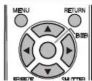
The menu system allows you to access functions which do not have their own dedicated buttons on the Remote control. The menu options are structured and categorized. You can navigate through the menu with buttons.
Navigating through the MENU
- Displaying the Main menu

Press the MENU button to display the Main menu and the operating guidance.
Operating guidance
Contains the required buttons to adjust the settings.
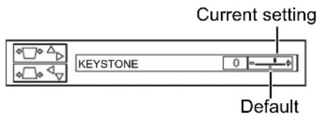
Adjusting with the bar scale items
The triangle mark under the bar indicates factory default setting and the square indicates the current setting.
- Returning to the previous menu
RETURN

Press the MENU or RETURN button to return to the previous menu. Press repeatedly to escape from the menu mode and return to the projection.
- Operating procedure
-
Press to scroll to the required Main menu item and press ENTER to select.
-
The selected item is highlighted in orange and the Sub-menu is displayed on the right.
See "Main menu and Sub-menu" on page 28.
-
Press to scroll to the required Sub-menu item and press or ENTER to adjust.
-
The selected item is called up and the other menu items disappear from the screen. Called up item will be disappear after 5 seconds and return to the menu mode.
- If there is a lower level, the next level will be displayed.
-
Press to adjust or set the selected item.
-
For items using a bar scale, the current settings are displayed on the left of the bar scale.
- You can cycle through the options of an item by pressing
- Press MENU or RETURN to return to the previous menu.
NOTE:
- See "Resetting to the factory default settings" on page 25 to reset each menu items.
- See "INITIALIZE ALL" on page 36 to reset all the settings.
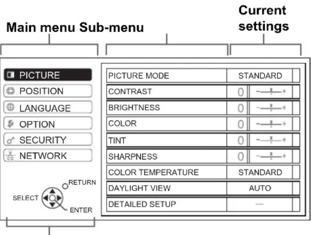
Main menu and Sub-menu
The Main menu has 6 options. Select the required menu item and press ENTER to display the Sub-menu.
NOTE:
- Some default settings vary by the selected input signal.
- Sub-menu items vary according to the selected input signal.
- Some settings are adjustable without any signals.
| Main menu | Sub-menu | Options (* is default setting) | Page | |
| PICTURE PICTURE MODE NATURAL | DYNAMIC*1STANDARD* BLACKBOARD | page 30 | ||
| CONTRAST · Default: 0 page | 30 | |||
| BRIGHTNESS · Default: 0 page 30 | ||||
| COLOR*2 | · Default: 0 page 30 | |||
| TINT*2 | · Default: 0 page 30 | |||
| SHARPNESS · Default: 0 page 30 | ||||
| COLOR TEMPERATURE | LOW STANDARD*HIGH | page 30 | ||
| DAYLIGHT VIEW | AUTO* ONOFF | page 30 | ||
| DETAILED SETUP*3 | WHITE BALANCE*4· Default: 0 | WHITE BALANCE REDWHITE BALANCE GREENWHITE BALANCE BLUE | page 31 | |
| TV-SYSTEM(S-VIDEO/VIDEOsignals only) | AUTO* NTSCNTSC 4.43 PALPAL-M PAL-NSECAM | |||
| STILL MODE(S-VIDEO/VIDEO) | OFF*ON | |||
| NOISE REDUCTION(S-VIDEO/VIDEO) | ON*OFF | |||
| POSITION | KEYSTONE*5 | · Default: 0 page 32 | ||
| POSITION | H · Default: 0 | page 32 | ||
| V · Default: 0 | ||||
| DOT CLOCK*4 | · Default: 0 page 32 | |||
| CLOCK PHASE*6 | · Default: 0 page 32 | |||
| ASPECT | 4:3 S4:316:9* AUTO | page 32 | ||
| FRAME LOCK | OFF* ON | page 33 | ||
| LANGUAGE | 1/2 | 2/2 | ||
| DEUTSCH | POLSKI | |||
| FRANÇAIS | ČEŠTINA | |||
| ESPAÑOL | MAGYAR | |||
| ITALIANO | PYCCKNI | |||
| PORTUGUES | LYNJU | |||
| SVENSKA | SANKHER | |||
| NORSK | ENGLISH | |||
| DANSK | 中文 | |||
| 日本語 | ||||
1. Default setting for COMPUTER/COMPONENT signals
2. Not available with COMPUTER/NETWORK signals
3. VIDEO/S-VIDEO/COMPUTER signals only
4. COMPUTER signals only
5. Only KESTONE is available with NETWORK signals
6. COMPUTER/COMPONENT signals only
| Main menu Sub-menu Options (* is default setting) Page | ||||
| OPTION | INPUT GUIDE | DETAILED* SIMPLEOFF | page 34 | |
| STARTUP LOGO ON* OFF page 34USER | ||||
| COMPUTER2 SELECT | INPUT* OUTPUT | page 34 | ||
| FILTER SETUP | 1*32 | page 34 | ||
| FILTER REMAINING | page 34 | |||
| LAMP RUNTIME | page 35 | |||
| POWER OFF TIMER | OFF*15 MIN.40 MIN.20 MIN.45 MIN.25 MIN.50 MIN.30 MIN.55 MIN.35 MIN.60 MIN. | page 35 | ||
| DIRECT POWER ON | OFF*ON | page 35 | ||
| CONTROL PANEL | VALID*INVALID | page 35 | ||
| AUTO SETUP | AUTO* BUTTON | page 35 | ||
| SIGNAL SEARCH | ON*OFF | page 35 | ||
| INSTALLATION | FRONT/DESK*REAR/DESKFRONT/CEILINGREAR/CEILING | page 35 | ||
| SCREEN FORMAT | 16:9*16:10 | page 35 | ||
| HIGHLIGHT | OFF*ON | page 36 | ||
| CLOSED CAPTION | CC1TT1TT2 | page 36 | ||
| TEST PATTERN | page 36 | |||
| DETAILED SETUP | OSD DESIGNTYPE1 TYPE2TYPE3 | page 36 | ||
| SXGA MODESXGA SXGA+ | ||||
| XGA MODEXGA WXGA | ||||
| BLACKBOARDON*OFF | ||||
| BACK COLORBLUE*BLACK | ||||
| VOLUME | ||||
| AUDIO BALANCE· Default: 0 | ||||
| INITIALIZE ALL | ||||
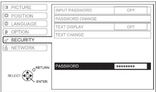
| SECURITY | INPUT PASSWORD | OFF*ON | page 37 | |
| password CHANGE | page 37 | |||
| TEXT DISPLAY | OFF*ON | page 37 | ||
| TEXT CHANGE | page 37 | |||
| NETWORK(See CD-ROMcontents) | WIRED LANWIRELESS LANNAME CHANGEINPUT PASSWORDPASSWDCHANGENetwork STANDBYWEB CONTROLLIVE MODE CUT INSTATUSINITIALIZE | page 38 | ||
PICTURE menu

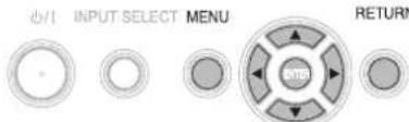
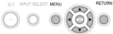
Remote control Control panel

边

INPUT SELECT MENU
LECT MENU


RETURN
See "Navigating through the MENU" on page 27.
See "Main menu and Sub-menu" on page 28.
PICTURE MODE
Depending on the projection environment, you can use these preset parameter settings to optimize image projection. Press to cycle through the options.
| NATURAL | Reproduces the original color of the image |
| STANDARD Setting for a general image | |
| DYNAMIC Bright and sharp setting | |
| BLACKBOARD | Setting for when projecting on a blackboardSee“BLACKBOARD”on page 36. |
NOTE:
- It may take for a while until the selected mode is stabilized.
CONTRAST
You can adjust the contrast of the projected image. Adjust the BRIGHTNESS in advance if necessary.
HigherLower
BRIGHTNESS
You can adjust the brightness of the projected image.
BrighterDarker
COLOR
You can adjust the color saturation of the projected image. (Available with VIDEO/S-VIDEO/COMPONENT signals only)
Lighter
Darker
TINT
You can adjust the skin tone in the projected image. (Available with VIDEO/S-VIDEO/COMPONENT signals only)
More reddish
More greenish
SHARPNESS
You can adjust the sharpness of the projected image.
Less sharp
More sharp
COLOR TEMPERATURE
You can adjust the white balance of the projected image.
LOW More bluish
STANDARD Balanced white
- HIGH More reddish
DAYLIGHT VIEW
You can keep the projected image bright and vivid even in well-lit rooms where the ambient light sources cannot be controlled, such as when a door opens or when window coverings fail to block out sunlight.
- AUTO: Automatic adjustment
ON:Active
OFF: Deactive
NOTE:
- Do not cover the ALS (Ambient Luminance Sensor) of the projector. See "ALS (Ambient Luminance Sensor)" on page 12.
- AUTO is not available when INSTALLATION setting in OPTION menu is set to REAR/DESK or REAR/CEILING.
DETAILED SETUP
You can perform more detailed image adjustment manually.
For S-VIDEO/VIDEO signals
TV-SYSTEM
When the video signal is changed, the setting switches automatically. You can switch the setting manually to match the video data. Press to cycle through the options.

NOTE:
- AUTO setting will select from NTSC/NTSC 4.43/PAL/ PAL60/PAL-M/PAL-N/SECAM.
- STILL MODE
You can reduce the vertical flicker when projecting a still image.
OFF: Deactive
ON: Active
NOTE:
- Set to OFF when projecting a moving image.
NOISE REDUCTION
You can switch the automatic noise reduction system on/off. Press to select the required setting.
- ON: Automatic noise reduction
OFF: No noise reduction
NOTE:
- Applying noise reduction may affect image quality.
For RGB signals
WHITE BALANCE
You can adjust the white balance more properly in 3 colors temperature by pressing
Remote control Control panel

07

INPUT SELECT MENU


RETURN
- See "Navigating through the MENU" on page 27.
See "Main menu and Sub-menu" on page 28.
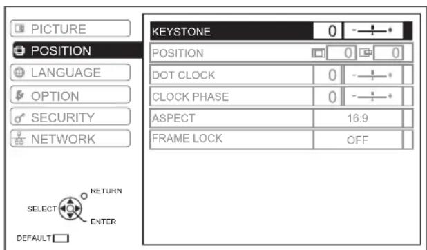
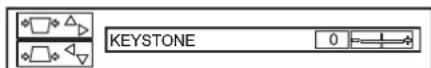
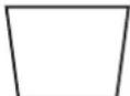
KEystone
If the projector is aligned non-perpendicularly to the screen, or if the projection screen has an angled surface, you can correct keystone.
Image Operation
NOTE:
- You can correct the distortion ± 30 degrees from the plane. For a better quality image, installing the projector with a minimum of distortion is recommended.
- Some distortion may be retained for lens shift adjustment.
- The distortion of the Main menu screen is not correctable.
- The result of the keystone correction will affect the aspect ratio and the size of the image.
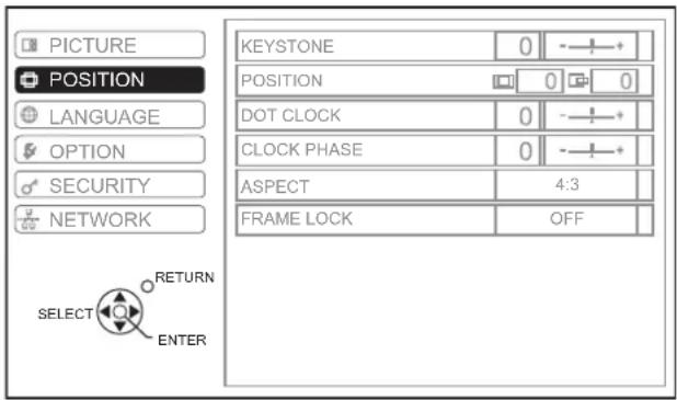
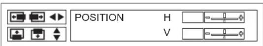
POSITION
You can move the projected image for fine adjustment.
Press to move horizontally and vertically.
(Available withVIDEO/S-VIDEO/COMPUTER/
COMPONENT signals only)
DOT CLOCK
If you have interference patterns of the projected image, which is sometimes referred to as moiré or noise, you can minimize it by pressing to adjust the clock frequency. (Available with signals from COMPUTER only)
NOTE:
- If the projecting signal's dot clock frequency is higher than 108 MHz, the adjustment may not make a difference.
- DOT CLOCK needs to be adjusted before adjusting the CLOCK PHASE.
CLOCK PHASE
If you require further adjustment for the same reason as the DOT CLOCK adjustment, you can fine adjust the timing of the clock. Press to adjust. (Available with signals from COMPUTER/COMPONENT only)
NOTE:
- If the projecting signal's dot clock frequency is higher than 108 MHz, the adjustment may not make a difference.
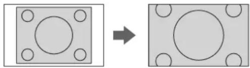
ASPECT
You can switch the aspect ratio manually when needed. Press to cycle through the options.

- Aspect ratio options

AUTO
Signals which contains an identifying signal will be detected and automatically project the image in proper ratio.

4:3
When a 4:3 or 5:4 signal is detected, the image will be projected without any change, and other signals will be adjusted to 4:3 with preserving original ratio.
→
→

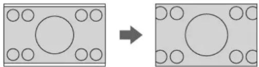
16:9
When a 16:10, 16:9 or 15:9 signal is detected, the image will be projected without any change, and other signals will be adjusted to 16:9.
→
→
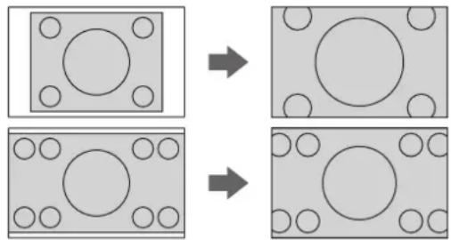
H-FIT
The 4:3/5:4 image will be stretched to the horizontal limit of the SCREEN FORMAT setting size with preserving original ratio and the vertical edge will be cropped.
V-FIT
The 16:9 (16:10)/15:9 image will be stretched to the vertical limit of the SCREEN FORMAT setting size with preserving original ratio and the horizontal edge will be cropped.
HV-FIT
The image will be stretched to the vertical and horizontal limit of the SCREEN FORMAT setting size with preserving original ratio and the vertical and horizontal edge will be cropped.
NOTE:
- If you project an image with an unmatched aspect ratio, the image may distort or some portions may be cropped. Select an aspect ratio which preserves the intention of the image creator.
- The order of ASPECT types is defined not only by the input method but also by the input signals. See "List of compatible signals" on page 44.
- If you project a copyrighted image enlarged or distorted by using ASPECT function in commercial use in a public place, such as a restaurant or hotel, you might infringe on the copyright of the creator which is protected by copyright law.
-
AUTO will not be selectable with some certain signals from VIDEO/S-VIDEO/COMPONENT.
-
Aspect ratio depend on signals and SCREEN FORMAT menu option
| SCREEN FORMAT menu | ASPECT menu |
| VIDEO/S-VIDEO/COMPONENT | |
| 16:10 | AUTO ▲ □ 4:3 ▲ □ 16:9 ▲ □ H-FIT ▲ □ HV-FIT |
| 16:9 | AUTO ▲ □ 4:3 ▲ □ H-FIT ▲ □ HV-FIT |
| ● ▲ 1 080/50i, 1 080/60i, 720/50p, 720/60p | |
| 16:10 | 16:9 ▲ □ V-FIT ▲ □ HV-FIT ▲ □ 4:3 |
| 16:9 Not | available |
| COMPUTER | |
| 16:10 | 4:3 ▲ □ 16:9 ▲ □ H-FIT ▲ □ HV-FIT |
| 16:9 | 4:3 ▲ □ H-FIT ▲ □ HV-FIT |
| ● ● WXGA768 | |
| 16:10 | 16:9 ▲ □ V-FIT ▲ □ HV-FIT ▲ □ 4:3 |
| 16:9 16:9 | ▲ □ HV-FIT |
| ● ● WIDE signals except WXGA768 | |
| 16:10 16:9 ▲ □ 4:3 | |
| 16:9 4:3 | ▲ □ HV-FIT |
FRAME LOCK
If the projected image is degraded, you can activate FRAME LOCK for synchronization. Press to select the required option.
OFF Deactive
ON Active
NOTE:
- This function is available with COMPUTER signals only.
OPTION menu
Remote control
Control panel
See "Navigating through the MENU" on page 27.
See "Main menu and Sub-menu" on page 28.
INPUT GUIDE
When you change the input method, the guidance appears in the upper right corner of the screen. The following display methods are available. Press to cycle through the options.
Options Function
| OFF Turn off the guidance. | |
| SIMPLE | Display the input method by text. The INPUT GUIDE will go out after 5 seconds without any operation. |
| DETAILED | Display the input method by graphic. The INPUT GUIDE will go out after 10 seconds without any operation. If you select any COMPUTER terminal which has no signal, the computer connection guidance will be displayed. See “Computer connection guidance” on page 46. |
STARTUP LOGO
You can switch the logo on/off that is displayed when starting up the projector. Press to select the required option. STARTUP LOGO will be displayed for 30 seconds.
ON Active
OFF Deactive
- USER Display the original text
Editing the original text
If you select USER, you can display the 2 lines of original text up to 40 characters in 1 line instead of the logo.
- Select USER and press ENTER.
- Select the required line to enter or edit the original text, and press ENTER.
-
Use to specify the location of the required character and press ENTER.
-
The selected character will be displayed in the box.
-
Select DELETE to delete the last entered character and press ENTER.
-
Repeat the step 3 until you finish the text to display in a line.
- Select OK and press ENTER to set the entered text in a box.
- Press and edit the TEXT2 if you need to, and repeat the step 3 - 5.
COMPUTER2 SELECT
You can switch the function of the COMPUTER2 IN/1 OUT terminal.
- INPUT COMPUTER2 IN
- OUTPUT COMPUTER1 OUT
FILTER SETUP
You can change the pace of the ARF (Auto Rolling Filter) performance for the use environment. Press to select the required option.
- 1 Ventilated with indoor air (e.g. small office room)
- 2 Ventilated with outdoor air (e.g. large office room, class room)
- 3 Public indoor space (e.g. restaurant, building lobby)
NOTE:
The ARF is a nonreusable product.
- Select the most suitable option for the use environment.
- If you select an unsuitable option, it may greatly affect on the duration of the projector life.
FILTER REMAINING
You can check the remaining amount of the ARF (Auto Rolling Filter). The color of the bar scale is indicating the condition of the ARF.
- Yellow The filter remaining amount is getting low.
Red No more remaining.
NOTE:
See "Replacing the ARF (Auto Rolling Filter)" on page 40.
- After you replace the ARF, FILTER REMAINING should be reset to "0" by pressing the ENTER button for 3 seconds.
LAMP RUNTIME
You can check how long the lamp has been used.
NOTE:
- LAMP RUNTIME is a relevant matter for lamp replacement timing. See "Replacing the Lamp unit" on page 41.
- When the lamp unit is replaced with the new one (ET-LAF100), the setting will be reset to "0".
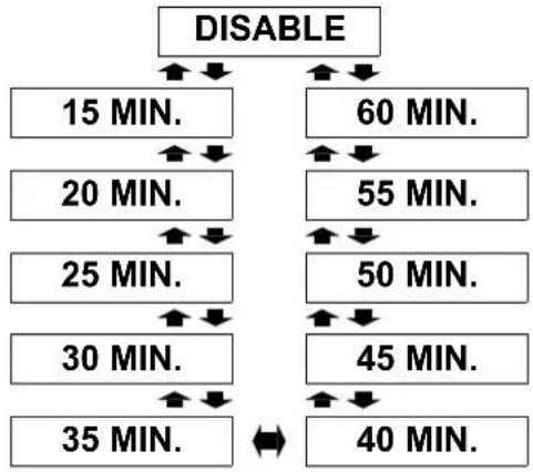
POWER OFF TIMER
You can set the off timer to switch off the POWER of the projector after a certain period of time automatically when no signal is detected. Press to select the required period from 15 to 60 minutes at intervals of 5 minutes.
DIRECT POWER ON
You can switch the projector start up status for when the Power cord is connected while the MAIN POWER is on, or for when the MAIN POWER is switched on while the Power cord is connected. Press to select the required option.
OFF The projector will start from the standby mode or the projecting mode.
- ON The projector will start from the projecting mode.
NOTE:
- When the projector is started from the projecting mode, pressing the POWER button procedure is skippable.
CONTROL PANEL
You can turn off the function of the control panel buttons on the projector body. Press to select the required option.
- INVALID
Invalidate the control panel buttons Confirmation screen will be displayed. - VALID Validate the control panel buttons
AUTO SETUP
You can turn off the AUTO SETUP function for when the COMPUTER signal is detected.
- AUTO When the projector detect a
COMPUTER signal, adjust the projected image position automatically for SIGNAL SEARCH, DOT CLOCK and CLOCK PHASE.
- BUTTON
Only when the AUTO SETUP button is pressed, the projected image position will be adjusted for DOT CLOCK and CLOCK PHASE. See "Remote control" on page 11.
NOTE:
Usually the recommended setting is AUTO.
SIGNAL SEARCH
You can turn off the auto signal detecting system.
ON Detect the input signal from the
terminals and project the image.
OFF Deactive
NOTE:
- SIGNAL SEARCH is not available when any input signal is projecting.
Usually the recommended setting is ON.
INSTALLATION
When installing the projector, select the projection method according to the projector position. Press to cycle through the options. See "Projection method" on page 15.
| FRONT/DESK | Setting on a desk/floor and projecting from front |
| FRONT/CEILING | Mounting in the ceiling and projecting from front |
| REAR/DESK | Setting on a desk/floor and projecting from rear |
| REAR/CEILING | Mounting in the ceiling and projecting from rear |
SCREEN FORMAT
Select the required screen format by pressing
- 16:10 When project on a 16:10 or 4:3 screen.
- 16:9 When project on a 16:9 screen.
HIGHLIGHT
If you use the projector at high elevation, the HIGHLAND setting need to be ON to set the fan speed high. Press
to select the required option.
- OFF The fan speed is low.
- ON The fan speed is high.
NOTE:
- At 1400 m (4593 ft) above sea level, the setting must be ON.
- The loudness of fan noise depends on the HIGHLAND setting.
CLOSED CAPTION
If the input signal contains closed captions, you can turn on the feature and switch the channels. Press to select the required option.
| OFF Deactive | |
| CC1 | Caption channels |
| CC2 | |
| TT1 | Text channels |
| TT2 |
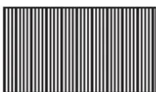
TEST PATTERN
You can use the 7 different test patterns to adjust the focus of the image. See "Lens shift and positioning" on page 16.
- Press ENTER to display the test pattern 1.
- Press to select the required test pattern.
- Adjust the focus with the Focus lever.
- Press MENU or RETURN to return to the previous menu, oar press repeatedly to escape the menu mode.
NOTE:
- When the projector and/or the screen is tilted, adjust the focus at the centre of the image. The upper and lower edge might be out of focus.
- When the image is distorted in keystone, adjust the KEystone in POSITION menu.
DETAILED SETUP
You can perform more detailed setting in various items.
OSD DESIGN
You can change the background color of the menu. Press to select the required option.
| TYPE1 Semi transparent black |
| TYPE2 Solid blue |
| TYPE3 Semi transparent dark blue |
SXGA MODE
You can switch the setting between SXGA and the larger setting, SXGA+. Press to select the required option.
WIDE MODE
You can turn ON/OFF the WIDE MODE setting.
ON For WIDE signals
- OFF For other type of signals
BLACKBOARD
You can exclude the BLACKBOARD in menu items of PICTURE MODE in PICTURE menu. Press to select the required option.
- ON Include the BLACKBOARD in menu items.
- OFF Exclude the BLACKBOARD in menu items.
BACK COLOR
You can choose a BLUE or BLACK screen for when the projector is idle. Press to select the required option.
VOLUME
You can adjust the volume of the built-in monaural speaker and VARIABLE AUDIO OUT terminal.
Decrease
- ▶ ▶ Increase
AUDIO BALANCE
You can adjust to hear the sound played equally through both right and left external stereospeakers, or shift the balance so more sound plays through the left or right side.
More sound plays through the left side
- More sound plays through the right side
- INITIALIZE ALL
You can reset all of the customized settings to the factory defaults except NETWORK, LAMP RUNTIME and FILTER REMAINING menu settings.
- Press the ENTER button
- Turn off the projector by pressing the POWER button.
- Switch off the MAIN POWER button to reset the projector.
- The minimum required setting screen will be displayed.
See "Minimum required setting screen" on page 10.
Remote control Control panel
See "Navigating through the MENU" on page 27.
See "Main menu and Sub-menu" on page 28.
- Entering the SECURITY menu
Every time when you apply to the SECURITY menu, you will be asked to perform the password operation.
When you apply to the SECURITY menu before you change the password to your original, perform to input the following factory default password operation.
Press ▲ ▶ △ ▷ ▼ and ENTER.
After you change the password
When you apply to the SECURITY menu after you change the password to your original in the PASSWORD CHANGE menu, input the original password operation.
NOTE:
- The factory default password is valid until you change the password in PASSWORD CHANGE menu.
- The entered password operations will appear as asterisks in the box.
INPUT PASSWORD
You can activate the security system and the password operation will be asked to perform when the projecting mode started. Unless you perform the correct password operation, all of the button controls will be disabled except the POWER button.
OFF Deactive
ON Active
NOTE:
- When you activated the security system, make sure to change the password to your original for safety.
- The factory default password is valid until you change the password in PASSWORD CHANGE menu.
password CHANGE
You can change the password operation to your original.
- Press a series of button operation up to 8 as a password by using and buttons.
- Press ENTER.
-
Press the exact same series of button operation you entered in the NEW password box for confirmation.
-
If a series of button operation is incorrect, you will be asked to perform again.
-
Press ENTER.
NOTE:
- The entered password operations will appear as asterisks in the box.
TEXT DISPLAY
You can set your original text, such as company name or URL information, to display regularly at the bottom of the projected image while projecting.
OFF Deactive
ON Active
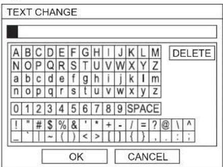
TEXT CHANGE
You can enter your original text up to 22 characters for TEXT DISPLAY.
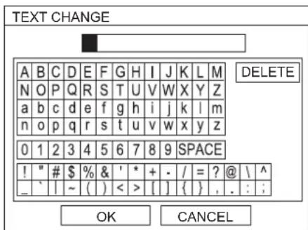
- Use to specify the location of the required character.
-
Press ENTER.
-
The selected character will be displayed in the TEXT CHANGE box.
-
Repeat until finish your original text.
- Select DELETE to delete the last entered character and press ENTER.
- Select OK and press ENTER to set the entered text.
- Select CANCEL or press MENU/RETURN buttons to return to the previous menu.
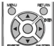
NETWORK menu
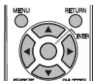
Remote control Control panel

0/1

INPUT SELECT MENU
RETURN
- See "Navigating through the MENU" on page 27.
See "Main menu and Sub-menu" on page 28.
NOTE:
See more detailed instructions in the contents of the CD-ROM which is provided with the projector.
Items in NETWORK menu
In NETWORK menu, the following items are available.
Wired LAN
WIRELESS LAN
- NAME CHANGE
- INPUT PASSWORD
- PASSWORD CHANGE
- NETWORK STANDBY
WEB CONTROL
- LIVE MODE CUT IN
STATUS
- ● INITIALIZE
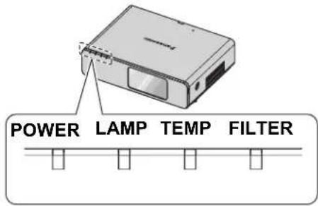
TEMP, LAMP and FILTER Indicators
Managing the indicated problems
If a problem should occur with the projector, the TEMP, LAMP and/or FILTER indicators will inform you. Manage the indicated problems as follow.
- Confirm the status of all indicators and projector, and switch off the projector in proper way.
- Find out the cause of the problem by status of the TEMP, LAMP and/or FILTER indicators.
- Follow the instruction for each indication below and solve the problem.
- Turn on the projector in the correct way and confirm the indicator is not indicating a problem any longer.
NOTE:
- If no problem is found or the problem remains, do not turn on the projector. Instead contact an Authorized Service Center.
LAMP indicator
| Indicator | ● Illuminating RED | ● Flashing RED | ||
| Problem | LAMP RUNTIME has reached 2 800 hours. | LAMP circuit failure, abnormal function or Lamp unit is damaged. | ||
| Cause | Lamp unit will run out soon and needs to be replaced. | The MAIN POWER is switched on again before the Lamp unit is cooled enough. | LAMP circuit failure, abnormal function. | Lamp unit is damaged. |
| Remedy | See “Replacing the Lamp unit” on page 41. | Let the Lamp unit cool down and turn on the MAIN POWER. | Contact an Authorized Service Center. | See “Replacing the Lamp unit” on page 41. |
TEMPindicator
| Indicator | ● Illuminating RED and still projecting ● Flashing RED and POWER is turned off | |||
| Problem The temperature inside and/or outside the projector is abnormally high. | ||||
| Cause | The ventilation openings are covered. | The room temperature is too high. | The ARF is excessively dirty and the ventilation is poor. | The projector is located at high elevations (above 1400 m). |
| Remedy | Remove the object(s) from the ventilation openings or clear around the projector. | Reinstall the projector in temperature controlled place. See page 48. | Replace the ARF in the proper method. See page 40. | Turn on the projector*1 and set the HIGHLAND to ON. See page 36. |
*1. The projector will perform only 2 minutes with OFF setting at high elevation.
- FILTER indicator
When the FILTER indicator is flashing GREEN, the ARF is normally rolling up.
| Indicator | ● Illuminating RED | ● Flashing RED | ● Illuminating ORANGE | ● Flashing ORANGE |
| Problem | FILTER REMAINING has turned red. See page 34. | The projector cannot detect the ARF. | The ARF cannot operate properly. | FILTER REMAINING has turned yellow. See page 34. |
| Cause | ARF has been run out. | ARF is not attached. | Foreign object is blocking the ARF operation. | ARF is running out. |
| Remedy | See "Replacing the ARF (Auto Rolling Filter)" on page 40. | Attach the ARF. | Remove the foreign object or contact an Authorized Service Center. | Prepare the ARF for replacement. |
Care and Replacement
Cleaning the projector
Before cleaning the projector
- Switch off the MAIN POWER and disconnect the power plug from the wall outlet.
- Unplug all the cables from the projector.
- Cleaning the outer surface of the projector
Wipe off dirt and dust gently with a soft cloth.
- If it is difficult to remove the dirt, soak a cloth in a neutral detergent diluted with water, wring the cloth well and then wipe the projector. Dry off the projector with dry cloth.
- If you use a chemical treated wipe, follow the instructions supplied with it.
- Cleaning the lens and front glass surface
Wipe off dirt and dust gently with a lint-free cloth.
- Make sure no dirt or dust remains on the surface of the lens. It will be enlarged and projected onto a screen.
Replacing the ARF (Auto Rolling Filter)
Before replacing the ARF
- Press the POWER button for at least 0.5 seconds or press twice to turn off the projector.
- Wit until the cooling fan stops and the POWER indicator turn to RED.
- Disconnect the Power cord from the main socket.
- Prepare a Phillips-head screw driver.
- Contact an Authorized Service Center to purchase a replacement ARF (ET-RFF100).
- When to replace the ARF
ARF is consumable product and effects on ventilation. FILTER indicator will inform you of the replacement timing. You can check the remaining amount of the ARF in FILTER REMAINING menu.
NOTE:
See "FILTER REMAINING" on page 34.
See "FILTER indicator" on page 39.
Replacement procedure
- Turn the projector upside down and place it gently on a soft cloth.
- Use a Phillips-head screwdriver to loosen 3 ARF cover fixing screws until the screws turn freely and remove the ARF cover.
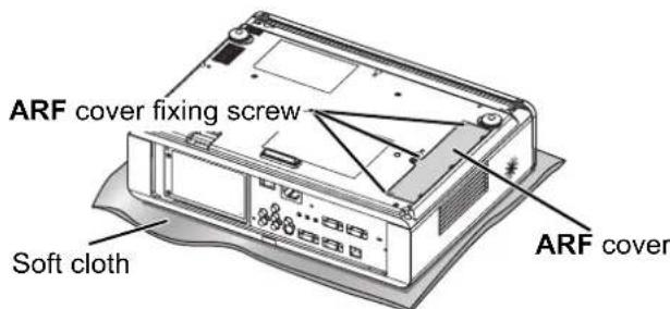
- Use a Phillips-head screwdriver to loosen an ARF fixing screws and release the clamp, then slightly slide up the used ARF to remove.
-
Insert the new ARF into the compartment in correct direction and slightly push down until it clicks. Tighten the ARF fixing screws securely with a Phillips-head screwdriver.
-
Attach the ARF cover and tighten the ARF cover fixing screws securely with a Phillips-head screwdriver.
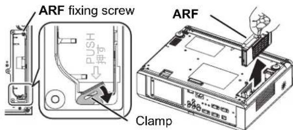
NOTE:
- If the ARF and/or ARF cover are attached incorrectly, the projector may not be turned on.
- Do not switch the power on while the ARF cover removed.
- When you replace the ARF unit, clean the compartment and/or the Air Exhaust port if you need to.
- Resetting the FILTER REMAINING
- Turn on the projector and display the FILTER REMAINING in OPTION menu. Press the ENTER button for 3 seconds and the confirmation screen will be displayed.
- Press to select OK and press the ENTER button to reset FILTER REMAINING to "0". See "FILTER REMAINING" on page 34.
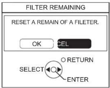
Replacing the Lamp unit
- Before replacing the Lamp unit
- Switch off the MAIN POWER and disconnect the power plug from the wall outlet.
- Make sure the Lamp unit and the surroundings are cooled enough.
- Prepare a Phillips-head screwdriver.
- Contact an Authorized Service Center to purchase a replacement Lamp unit (ET-LAF100).
- When the projector is mounted in the ceiling, do not work directly under the projector or put your face closer to the projector.
NOTE:
- Prior to replacing the lamp unit, allow it to cool down to prevent the risk of burns, damage and other hazards.
Do not attempt replacement with an unauthorized lamp unit.
- When to replace the Lamp unit
The Lamp unit is consumable and the brightness decreases by duration of usage. The LAMP indicator will inform you of the replacement timing at 2 800 hours, and at 3 000 hours, the projector will be turned off. Those figures are rough guidance and might be shortened by the usage conditions, characteristics of the Lamp unit, environmental conditions, and so on. You can check the duration of usage time using LAMP RUNTIME in the OPTION menu.
| Indication | On screen REPLACE LAMP | LAMP indicator LAMP |
| Over 2 800 hours | "REPLACE LAMP" is displayed on the upper left of the screen for 30 seconds. | Illuminates RED. |
| Over 3 000 hours | "REPLACE LAMP" is displayed on the upper left of the screen, and it will stay until you respond. To clear the screen, press any button. |
NOTE:
The guide times, 2 800 and 3 000 hours, are rough estimates based on certain conditions and is not a guaranteed time.
- For more information about the Lamp unit, such as guaranteed time, see the instructions which is provided with the Lamp unit.
- Replacement procedure
- Removing and replacing the lamp unit
- Use a Phillips-head screwdriver to loosen the 2 Lamp unit cover fixing screws on the back of the projector until the screws turn freely, and remove the Lamp unit cover.
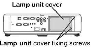
- Use a Phillips-head screwdriver to loosen the 2 Lamp unit fixing screws.
- Hold the handles of the Lamp unit and release the lamp unit lock.
- Pull the used Lamp unit gently from the projector.
Lamp unit fixing screws
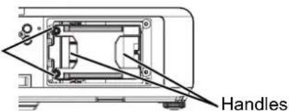
- Replace the new Lamp unit in correct direction. LAMP RUNTIME will be reset to "0" automatically.
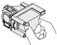
- Press in the Lamp unit until it clicks and make sure the unit is installed securely.
- Tighten the 2 Lamp unit fixing screws securely with a Phillips-head screwdriver.
Lamp unit fixing screws
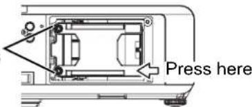
- Attach the Lamp unit cover and tighten the 2 Lamp unit cover fixing screws securely with a Phillips-head screwdriver.
Ceiling mount bracket safeguards
The projector and the ceiling mount bracket are designed sufficiently safety though, make sure the safety cable provided with the projector is installed and attached to the bottom of the projector when mounting in the ceiling for safety and security.
NOTE:
- Even if it is guarantee period, the manufacturer is not responsible for any hazard or damage caused by using a ceiling mount bracket which is not purchased from an authorized distributors, or environmental conditions.
- Make sure to use a torque driver and do not use an electrical screwdriver or an impact screwdriver.
- Installation work of the ceiling mount bracket should only be carried by a qualified technician.
- Remove an unused ceiling mount bracket promptly.
- Installing the safety cable
- Install the ceiling mount bracket according to the installation instructions.
- Loop the security cable around the ceiling mount bracket with less slack.
- Lace the cable of the end with a latch through the loop on the other end of the cable.
- Attach the latch on to the bottom of the projector with a provided screw.
- Torque: 1.25 ± 0.2 ~N · m
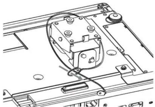
* Indicated above is ET-PKX100S.
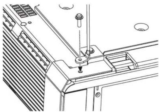
Troubleshooting
Should any problem persist, contact your dealer.
| Problem Cause | Reference page | |
| Power does not turn on. | The power cord may not be connected. The MAIN POWER switch is turned off. No electric supply is at the wall outlet. TEMP indicator is lit or flashes. LAMP indicator is lit or flashes. The lamp unit cover has not been securely installed. The circuit breakers have tripped. | 20 21 20 39 39 42 - |
| No picture appears. | The video signal input source may not be connected to a terminal properly. The input selection setting may not be correct. The BRIGHTNESS adjustment setting may be at the minimum setting. The SHUTTER function may be in use. | 19 24 30 25 |
| The picture is fuzzy. | The lens focus may not have been set correctly. The projector may not be at the correct distance from the screen. The lens may be dirty. The projector may be tilted too much. | 22 14 9 16 |
| The color is pale or greyish. | COLOR or TINT adjustment may be incorrect. The input source which is connected to the projector may not be adjusted correctly. | 30 28 |
| No sound can be heard from the internal speaker. | The audio signal source may not be connected properly. A cable may be connected to the VARIABLE AUDIO OUT terminal. The volume adjustment may be at the lowest possible setting. | 18 13 26 |
| The control buttons of the projector do not operate. | CONTROL PANEL in OPTION menu is invalidated. If you have a loss of the Remote control while the CONTROL PANEL is invalidated, press and hold the MENU button for 2 seconds with pressing the ENTER button. | 35 |
| The Remote control does not operate. | The batteries may be weak. The batteries may not have been inserted correctly. The remote control signal receptor on the projector may be obstructed. The remote control unit may be out of the operation range. | - 11 23 23 |
| The picture does not display correctly. | The signal format (TV-SYSTEM) may not have been set correctly. There may be a problem with the VCR or other signal source. A signal which is not compatible with the projector is being input. | 31 - 44 |
| Picture from a computer does not appear. | The cable may be longer than the optional cable. The external video output from a laptop computer may not be correct. (You may be able to change the external output settings by pressing the [Fn] + [F3] or [Fn] + [F10] keys simultaneously. The actual method varies depending on the type of computer; refer to the documentation provided with your computer for further details.) COMPUTER2 SELECT setting in OPTION menu is not correct. | - 46 34 |
Technical Information
List of compatible signals
| Mode | Display resolution (dots)*1 | Scanning frequency | Dot clock frequency (MHz) | Picture quality*2 | Terminals | |
| H (kHz) V (kHz) | ||||||
| NTSC/NTSC 4.43/PAL-MPAL60 | 720 x 480i 15.7 | 59.9 - A | VIDEO/S-VIDEO | |||
| PAL/PAL-N/SECAM 720 x 576i | 576i 15.6 50.0 - A | |||||
| 480i 720 x 480i 15 | 7 59.9 13.5 A | COMPONENT/COMPUTER*3 | ||||
| 576i 720 x 576i 15 | 6 50.0 13.5 A | |||||
| 480p 720 x 483 | 31.5 59.9 27.0 A | |||||
| 576p 720 x 576 | 31.3 50.0 27.0 A | |||||
| 1 080/60i | 1 920 x 1 080i | 33.8 60.0 | 74.3 A | |||
| 1 080/50i | 1 920 x 1 080i | 28.1 50.0 | 74.3 A | |||
| 720/60p | 1 280 x 720 | 45.0 60.0 | 74.3 A | |||
| 720/50p | 1 280 x 720 | 37.5 50.0 | 74.3 A | |||
| VESA | 640 x 400 | 31.5 70.1 | 25.2 A | COMPUTER | ||
| 640 x 400 | 37.9 85.1 | 31.5 A | ||||
| VGA480 | 640 x 480 | 31.5 59.9 | 25.2 A | |||
| 640 x 480 | 35.0 66.7 | 30.2 A | ||||
| 640 x 480 | 37.9 72.8 | 31.5 A | ||||
| 640 x 480 | 37.5 75.0 | 31.5 A | ||||
| 640 x 480 | 43.3 85.0 | 36.0 A | ||||
| SVGA | 800 x 600 | 35.2 56.3 | 36.0 A | |||
| 800 x 600 | 37.9 60.3 | 40.0 A | ||||
| 800 x 600 | 48.1 72.2 | 50.0 A | ||||
| 800 x 600 | 46.9 75.0 | 49.5 A | ||||
| 800 x 600 | 53.7 85.1 | 56.3 A | ||||
| MAC 832 x 624 | 49.7 74.6 57.3 A | |||||
| XGA | 1 024 x 768 | 39.6 50.1 | 51.9 A | |||
| 1 024 x 768 | 48.4 60.0 | 65.0 A | ||||
| 1 024 x 768 | 56.5 70.1 | 75.0 A | ||||
| 1 024 x 768 | 60.0 75.0 | 78.8 A | ||||
| 1 024 x 768 | 68.7 85.0 | 94.5 A | ||||
| MXGA | 1 152 x 864 | 64.0 71.2 | 94.2 A | |||
| 1 152 x 864 | 67.5 74.9 | 108.0 A | ||||
| 1 152 x 864 | 76.7 85.0 | 121.5 A | ||||
| MAC | 1 152 x 870 | 68.7 | 75.1 | 100.0 | A | |
| MSXGA | 1 280 x 960 | 60.0 | 60.0 | 108.0 | A | |
| SXGA | 1 280 x 1 024 | 64.0 | 60.0 | 108.0 | A | |
| 1 280 x 1 024 | 80.0 75.0 | 135.0 A | ||||
| 1 280 x 1 024 | 91.1 85.0 | 157.5 A | ||||
| SXGA60+ | 1 400 x 1 050 | 64.0 | 60.0 | 108.0 | A | |
| 1 400 x 1 050 | 65.1 59.9 | 122.4 A | ||||
| UXGA | 1 600 x 1 200 | 75.0 | 60.0 | 162.0 | A | |
| WXGA | 1 280 x 768 | 39.6 49.9 | 65.3 A | |||
| 1 280 x 768 | 47.8 59.9 | 79.5 A | ||||
| 1 280 x 800 | 41.3 50.0 | 68.0 | AA | |||
1. The "i" appearing after the resolution indicates an interlaced signal.
2. The following symbols are used to indicate picture quality. AA Maximum picture quality can be obtained.
A Signals are converted by the image processing circuit before picture is projected.
*3. YP _B PR signals are available with COMPONENT terminal, and RGBHV signals are available with COMPUTER terminals.
Serial terminal
The serial connector which is on the connector panel of the projector conforms to the RS-232C interface specification, so that the projector can be controlled by a personal computer which is connected to this connector.
- Connection

Pin assignments and signal names
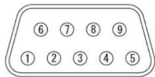
| Pin No. Signal name Contents | ||
| ① | NC | |
| ② | TXD Transmitted data | |
| ③ | RXD Received data | |
| ④ | NC | |
| ⑤ | GND Earth | |
| ⑥ | NC | |
| ⑦ | RTS | Connected internally |
| ⑧ | CTS | |
| ⑨ | NC | |
- Communication settings
| Signal level | RS-232C | Character length | 8 bits |
| Sync. method | Asynchronous | Stop bit | 1 bit |
| Baud rate | 9 600 bps | X parameter | None |
| Parity | None | S parameter | None |
Basic format
| STX | Command | : | Parameter | ETX |
| Start byte (02h) | 3 bytes | 1 byte | 1 byte - 4 bytes | End (03h) |
- The projector can not receive any command for 10 seconds after the lamp is switched on. Wait 10 seconds before sending the command.
- If sending multiple commands, check that a response has been received from the projector for one command before sending the next command.
- When a command which does not require parameters to be sent, the colon (:) is not required.
- If an incorrect command is sent from the personal computer, the ER401 command will be sent from the projector to the personal computer.
Cable specifications
(When connected to a personal computer)
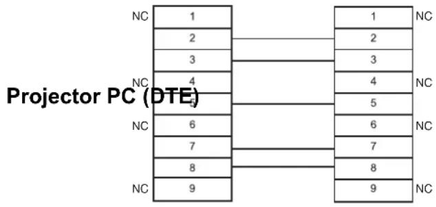
Control commands
| Command Control contents Remarks | ||
| PON Power ON | In standby mode, all commands other than the PON command are ignored. ●●The PON command is ignored during lamp ON control. | |
| POF Power OFF | If a PON command is received while the cooling fan is operating after the lamp has switched off, the lamp is not turned back on again straight away in order to protect the lamp. | |
| AVL Volume | Parameter 000 - 063 (Adjustment value 0 - 63) | |
| IIS INPUT | Parameter: VID = VIDEO SVD = S-VIDEO RG1 = COMPUTER1 RG2 = COMPUTER2 NWP = WIRELESS | |
| Q$S | Lamp condition query | Call back 0 = Standby 2 = Lamp ON 1 = Lamp ON control active 3 = Lamp OFF control active |
| OSH SHUTTER | Turning off the projection temporarily. Send the command to switch between ON and OFF. Do not send the command consecutively. | |
Computer connection guidance
You can switch the signals which to output from the COMPUTER1 OUT terminal by pressing the computer key command. The key commands are depend on the manufactures. If you select the computer terminals which has no signals while the INPUT GUIDE is set to DETAILED, the computer connection guidance will be displayed.
| Manufacturer | Key command | Manufacturer | Key command | Manufacturer | Key command |
| Panasonic NEC | Fn + F3 | TOSHIBA SHARP HP | Fn + F5 | IBM SONY | Fn + F7 |
| Apple | F7 | ||||
| FUJITSU | Fn + F10 | EPSON DELL | Fn + F8 | Other | Fn + ☐/☐ |
NOTE:
- The computer connection guidance will disappear after 5 minutes.
- Please refer the instructions which provided with the computers for more detailed information.
REMOTE terminal
You can remotely operate the projector from the outside the Remote control range by connecting to the REMOTE terminal.
Pin assignments and signal names
LAMP switching
| Pin No. Signal name Contents | ||
| ① | GND Ground | |
| ② | POWER POWER ON | |
| ③ | INPUT SEL3 Select input signal 3 | |
| ④ | NC | |
| ⑤ | INPUT SEL1 Select input signal 1 | |
| ⑥ | INPUT SEL2 Select input signal 2 | |
| ⑦ | Connect internally | |
| ⑧ | ||
| ⑨ | ENABLE Control by external contact | |
Switching input signals
| Pin No. Settings | ||
| ② - ① | Short Open | |
| Operation On Off | ||
| Pin No. Settings | ||||||
| ③ - ① | Open Open | Short Short | Short Open | |||
| ⑤ - ① | Open Short | Open Open | Short Short | |||
| ⑥ - ① | Open Open | Short Open | Open Short | |||
| Input signal | COMPUTER1 | COMPUTER2 | COMPONENT | VIDEO | S-VIDEO | NETWORK |
NOTE:
- When pin ① and pin ⑨ are short-circuited, the buttons on the projector's control panel, POWER and INPUT SELECT buttons on the Remote control cannot be used. In addition, the RS-232C commands and network functions that correspond to these functions cannot be used either.
- While pin ⑨ is "Open", do not short-circuit pin ①, ②, ③, ⑤ and ⑥. The projector would reject all the signals from the Remote control.
Specifications
| Power supply AC 100 - 240 V 50 Hz/60 Hz | ||
| Power consumption | 350 W During standby (when fan is stopped): 4 W | |
| Amps 4.1 A - 1.5 A | ||
| LCD panel | Panel size (diagonal) 0.74 type (17.78 mm) | |
| Aspect ratio 16:10 | ||
| Display method 3 transparent LCD panels (RGB) | ||
| Drive method Active matrix method | ||
| Pixels 1 024 000 (1 280 x 800) x 3 panels | ||
| Lens | Manual zoom (2x)/Manual focus F 1.7 - 2.6, f 21.6 mm - 43.0 mm | |
| Lamp UHM lamp (250 W) | ||
| Luminosity 3 000 lm | ||
| Operating environment | 0 °C - 40 °C (32 °F - 104 °F) When the HIGHLAND (page 36) is set to ON: 0 °C - 35 °C (32 °F - 95 °F) Humidity 20% - 80% (no condensation) | |
| Scanning frequency*1(for RGB signal) | Horizontal scanning frequency | 15 kHz - 91 kHz |
| Vertical scanning frequency | 50 Hz - 85 Hz | |
| Dot clock frequency Less than 108 MHz | ||
| COMPONENT (YPBPR) signals | 525i (480i), 525p (480p), 625i (576i), 625p (576p), 750 (720)/60p, 750 (720)/50p, 1 125 (1 080)/60i, 1 125 (1 080)/50i | |
| Color system | 7 (NTSC/NTSC 4.43/PAL/PAL-M/PAL-N/PAL60/SECAM) | |
| Projection size | 33" - 300" (838.2 mm - 7 620 mm) | |
| Throw distance | 1.1 m - 17.2 m (3'7" - 56'5") | |
| Screen aspect ratio | 16:10 | |
| Installation | FRONT/DESK, FRONT/CEILING, REAR/DESK, REAR/CEILING (Menu selection method) | |
| Speaker | 1 piece 4 cm (1 - 9/16") | |
| Max. usable volume output | 3.0 W | |
*1. See "List of compatible signals" on page 44 for available signals.
| Terminals | S-VIDEO IN | Single - line, Mini DIN 4p Y: 1.0 V [p-p], C: 0.286 V [p-p], 75Ω |
| VIDEO IN | Single - line, RCA pin jack 1.0 V [p-p], 75Ω | |
| COMPONENT1 IN | Single - line, D - sub HD 15-pin (female) R.G.B. 0.7 V [p-p], 75Ω TTL high impedance, automatic HD, VD/SYNC positive/negative polarity compatible | |
| COMPUTER2 IN/1 OUT | Single - line, D - sub HD 15-pin (female) Selectable for input and output by menu operation. R.G.B. 0.7 V [p-p], 75Ω TTL high impedance, automatic positive/negative polarity compatible | |
| COMPONENT IN | Y, PB/CB, PR/CR Single - line, RCA pin jack x 3 Y: 1.0 V [p-p] (including sync), 75Ω PB/CB, (PR/CR) 0.7 V [p-p], 75Ω | |
| AUDIO IN Single - line, 0.5V [rms], RCA pin jack x 2 (L - R) | ||
| COMPUTER AUDIO IN | Dual - line, 0.5V [rms], M3 jack (Stereo MINI) | |
| VARIABLE AUDIO OUT | Single - line, 0.5V [rms], M3 jack (Stereo MINI) Monitor output/stereo compatible 0 V [rms] - 2.0 V [rms] (variable) | |
| SERIAL D-sub 9-pin RS | 232C compatible | |
| REMOTE D-sub 9-pin For external control | ||
| LAN (RJ-45) | Single - line, For network connection 10 Base-T/100Base-TX/1000Base-T | |
| Wireless LAN | Compatible | IEEE802.11b/IEEE802.11g (Wireless LAN standard protocol) |
| Wireless channel IEEE802.11b/IEEE802.11g: 1 - 13 channels | ||
| Distance 30 m (98'5") Depends on the usage environment | ||
| Cabinet Moulded plastic (PC+ABS) | ||
| Dimensions | Width 432 mm (17")Height 124.5 mm (4 - 7/8")Length 319 mm (12 - 17/32") | |
| Weight | 6.2 kg (13.7 lbs.) | |
| Certifications | UL60950-1 C-UL FCC Class B ICES-003 | |
| Remote control | Power supply | 3 V DC (AA battery x 2) |
| Operating range | Approx. 15 m (49'2") (when operated directly in front of signal receptor) | |
| Weight | 117 g (4.2 ozs.) (including batteries) | |
| Dimensions | Width 48 mm (1 - 7/8")Length 163 mm (6 - 13/32")Height 24.5 mm (-15/16") (not including surface projection parts) | |
| Options | Ceiling bracket | ET-PKF100H/ET-PKF100S |
Screen size and throw distance for 16:9 aspect ratio
| Projection size (16 : 9) Throw distance (L) | ||||
| Screen diagonal (SD) | Screen height (SH) | Screen width (SW) | Minimum distance (LW) | Maximum distance (LT) |
| 33" (0.84 m) 0.4 | 1 m (1'4") 0.73 m (2'4") | 1.9 m (6'2") | ||
| 40" (1.02 m) 0.5 | m (1'7") 0.89 m (2'1") | 1.2 m (3'11") 2.3 m | (7'6") | |
| 50" (1.27 m) 0.6 | m (2') 1.11 m (3'7") | 1.5 m (4'11") 2.9 m | (9'6") | |
| 60" (1.52 m) | 0.75 m (2'5") | 1.33 m (4'4") | 1.7 m (5'6") | 3.5 m (11'5") |
| 70" (1.78 m) 0.8 | m (2'10") 1.55 m (5'1") | 2.0 m (6'6") 4.1 m | (13'5") | |
| 80" (2.03 m) | 1.00 m (3'3") | 1.77 m (5'9") | 2.3 m (7'6") | 4.7 m (15'5") |
| 90" (2.29 m) | 1.12 m (3'8") | 1.99 m (6'6") | 2.6 m (8'6") | 5.3 m (17'4") |
| 100" (2.54 m) | 1.25 m (4'1") | 2.21 m (7'3") | 2.9 m (9'6") | 5.9 m (19'4") |
| 120" (3.05 m) | 1.49 m (4'10") | 2.66 m (8'8") | 3.5 m (11'5") | 7.1 m (23'3") |
| 150" (3.81 m) | 1.87 m (6'1") | 3.32 m (10'10") | 4.4 m (14'5") | 8.8 m (28'10") |
| 200" (5.08 m) | 2.49 m (8'2") | 4.43 m (14'6") | 5.9 m (19'4") | 11.8 m (38'8") |
| 250" (6.35 m) | 3.11 m (10'2") | 5.53 m (18'1") | 7.4 m (24'3") | 14.7 m (48'2") |
| 300" (7.62 m) | 3.74 m (12'3") | 6.64 m (21'9") | 8.9 m (29'2") | 17.7 m (58') |
- All measurements above are approximate and may differ slightly from the actual measurements.
Calculation methods for screen dimensions
You can calculate more detailed screen dimension from the screen diagonal.
$$ \begin{array}{l} \mathrm {S W} (\mathrm {m}) = \mathrm {S D} (") \times 0. 0 2 2 1 \mathrm {S H} (\mathrm {m}) = \mathrm {S D} (") \times 0. 0 1 2 5 \ L W (m) = 0. 0 2 9 7 \times S D \left("\right) - 0. 0 4 5 L T (m) = 0. 0 5 9 2 \times S D \left("\right) - 0. 0 6 1 \ \end{array} $$
- The results above are approximate and may differ slightly from the actual measurements.
Screen size and throw distance for 4:3 aspect ratio
| Projection size (4 : 3) | Throw distance (L) | |||
| Screen diagonal (SD) | Screen height (SH) | Screen width (SW) | Minimum distance (LW) | Maximum distance (LT) |
| 33" (0.84 m) 0.50 | m (1'7") 0.67 m (2'2") | 2.1 m (6'10") | ||
| 40" (1.02 m) 0.61 | m (2') 0.81 m (2'7") | 1.3 m (4'3") | 2.6 m (8'6") | |
| 50" (1.27 m) 0.76 | m (2'5") 1.02 m (3'4") | 1.6 m (5'2") | 3.2 m (10'5") | |
| 60" (1.52 m) | 0.91 m (2'11") | 1.22 m (4') | 1.9 m (6'2") | 3.9 m (12'9") |
| 70" (1.78 m) 1.07 | m (3'06") 1.42 m (4'7") | 2.3 m (7'6") | 4.5 m (14'9") | |
| 80" (2.03 m) | 1.22 m (4') | 1.63 m (5'4") | 2.6 m (8'6") | 5.2 m (17') |
| 90" (2.29 m) | 1.37 m (4'5") | 1.83 m (6') | 2.9 m (9'6") | 5.8 m (19') |
| 100" (2.54 m) | 1.52 m (4'11") | 2.03 m (6'7") | 3.2 m (10'5") | 6.5 m (21'3") |
| 120" (3.05 m) | 1.83 m (6') | 2.44 m (8') | 3.9 m (12'9") | 7.8 m (25'7") |
| 150" (3.81 m) | 2.29 m (7'6") | 3.05 m (10') | 4.9 m (16') | 9.8 m (32'1") |
| 200" (5.08 m) | 3.05 m (10') | 4.06 m (13'3") | 6.5 m (21'3") | 13.0 m (42'7") |
| 250" (6.35 m) | 3.81 m (12'6") | 5.08 m (16'8") | 8.2 m (26'10") | 16.3 m (53'5") |
| 300" (7.62 m) | 4.57 m (14'11") | 6.10 m (20') | 9.8 m (32'1") | 19.5 m (63'11") |
- All measurements above are approximate and may differ slightly from the actual measurements.
Calculation methods for screen dimensions
You can calculate more detailed screen dimension from the screen diagonal.
$$ \begin{array}{l} \mathrm {S W} (\mathrm {m}) = \mathrm {S D} (^ {\prime \prime}) \times 0. 0 2 0 3 \mathrm {S H} (\mathrm {m}) = \mathrm {S D} (^ {\prime \prime}) \times 0. 0 1 5 2 \ L W (m) = 0. 0 3 3 9 \times S D \left("\right) - 0. 0 5 2 L T (m) = 0. 0 6 5 3 \times S D \left("\right) - 0. 0 5 2 \ \end{array} $$
- The results above are approximate and may differ slightly from the actual measurements.
Dimensions
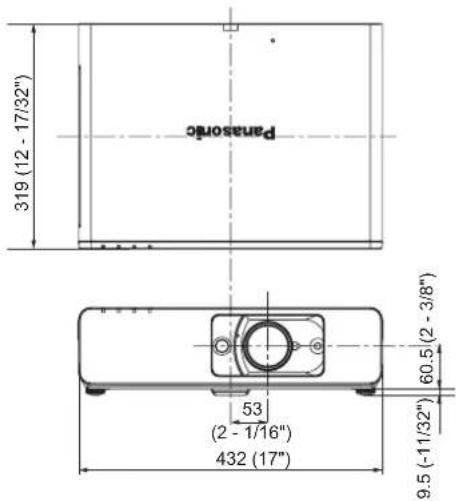
Unit: mm
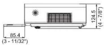
Trademark acknowledgements
- VGA and XGA are trademarks of International Business Machines Corporation.
S-VGA is a registered trademark of the Video Electronics Standards Association. - HDMI, the HDMI logo and High-Definition Multimedia Interface are trademarks or registered trademarks of HDMI Licensing LLC.
The font used in the on-screen displays is a Ricoh bitmap font, which is manufactured and sold by Ricoh Company, Ltd.
All other trademarks are the property of the various trademark owners.
Index
A
AC IN 13
Accessories 9
Air exhaust port 13
Air intake port 12
ALS (Ambient Luminance Sensor) 12
ARF (Auto Rolling Filter)
Compartment 13
FILTER indicator 12
FILTER indicator status 39
FILTER REMAINING 34
Replacing 40
ASPECT 32
AUDIO BALANCE 36
AUDIO IN 13
AUTO SETUP
Menu 35
Remote control 23
Remote control button 11
B
BACK COLOR 36
Battery compartment 11
BLACKBOARD 36
BRIGHTNESS 30
C
Calculation methods
16:10 14
16:9 50
4:3 50
CD-ROM
Accessories 9
Cleaning 40
CLOCK PHASE 32
CLOSED CAPTION 36
COLOR 30
COLOR TEMPERATURE 30
COMPONENT IN 13
COMPUTER
Connection guidance 46
Remote control 24
Remote control button 11
COMPUTER AUDIO IN 13
COMPUTER SEARCH 11
COMPUTER1 IN 13
COMPUTER2 IN/1 OUT 13
COMPUTER2 SELECT 34
Connections 18
CONTRAST 30
CONTROL PANEL 35
D
DAYLIGHT VIEW 30
DEFAULT
Remote control 25
Remote control button 11
DETAILED SETUP
OPTION menu 36
PICTURE menu 31
DIGITAL ZOOM
Remote control 26
Remote control button 11
Dimensions 51
Direct power off 20
DIRECT POWER ON
Function 20
Menu 35
DOT CLOCK 32
DOUBLEE-WINDOW 26
E
ENTER
Control panel button 12
Remote control button 11
F
FILTER REMAINING 34
FILTER SETUP 34
Focus lever 12, 22
FRAME LOCK 33
FREEZE
Remote control 25
Remote control button 11
Front leg adjusters 13, 15, 22
Front panel cover 12
H
Hand strap 11
HIGHLAND 36
1
INDEX-WINDOW
Remote control 25
Remote control button 11
INITIALISE ALL 36
INPUTGUIDE 34
INPUT PASSWORD 37
INPUT SELECT
Control panel button 12
Remote control button 11
Selecting 22, 24
INSTALLATION
Menu 35
Projection method 15
K
KEystone 32
L
LAMP
Indicator 12
Indicator status 39
LAMP RUNTIME 35
Lamp unit compartment 13
Replacing 41
LAN 13
LANGUAGE 28
LASER
Remote control 24
Remote control button 11
Lens shift lever 12, 16, 22
Lever
Focus lever 12
Lens shift lever 12
Zoom lever 12
M
Mains lead
Accessories 9
Connecting 20
MENU
Control panel button 12
Main menu 28
Navigation 27
Remote control button 11
N
Navigation buttons
Control panel button 12
Remote control button 11
NETWORK
Remote control 24
Remote control button 11
NOISE REDUCTION 31
0
OPTION menu 34
OSD DESIGN 36
P
PAGE 11
password CHANGE 37
PICTURE menu 30
PICTURE MODE 30
POSITION 32
POSITION menu 32
POWER
Control panel 12
Indicator 12
Indicator status 20
Remote control button 11
POWER OFF TIMER 35
Projection lens 12
R
REMOTE 13
LAMP switching 47
Pin assignments 47
Switching input signals 47
Remote control
Accessories 9
Indicator 11
Signal emitter 11
Signal receptor 12
RETURN
Control panel button 12
Remote control button 11
s
Safety cable
Accessories 9
Safeguards 42
SCREEN FORMAT 35
Screen size
16:10 14
16:9 50
4:3 50
Security lock 13
SECURITY menu 37
SERIAL 13
Basic format 45
Cable specifications 46
Communication settings 45
Connection 45
Control commands 46
Pin assignments 45
SHARPNESS 30
SHUTTER
Remote control 25
Remote control button 11
SIGNAL SEARCH 35
Speaker 12
Specifications 48
STARTUPLOGO 34
STILL MODE 31
Sub-menu 28
S-VIDEO IN 13
SXGA MODE 36
T
Technical Information 44
TEMP Indicator 12
Indicator status 39
TEST PATTERN 36
TEXT CHANGE 37
TEXT DISPLAY 37
Throw distance
16:10 14
16:9 50
4:3 50
Throwing angle 15
TINT 30
Troubleshooting 43
TV-SYSTEM 31
V
VARIABLE AUDIO OUT 13
VIDEO
Remote control 24
Remote control button 11
VIDEO IN 13
VOLUME 36
Remote control 26
Remote control button 11
W
WHITE BALANCE 31
WIDE MODE 36
Z
Zoom lever 12, 22
Cher client Panasonic:
Pursuant to at the directive 2004/108/EC, article 9(2)
Panasonic Testing Centre
Panasonic Service Europe, a division of Panasonic Marketing Europe GmbH
Winsbergring 15, 22525 Hamburg, F.R. Germany
NOTICE:
Fabricant responsible: Panasonic Corporation of North America
Adresse: One Panasonic Way, Secaucus, New Jersey 07094
Telephone: (888) 411-1996
Email: projectorsupport@us.panasonic.com
This product contains a CR Coin Cell Lithium Battery which contains Perchlorate Material - special handling may apply.
See www.dtsc.ca.gov/hazardouswaste/perchlorate.
Panasonic®
Projectors
Panasonic Projector Systems Company
Unit of Panasonic Corporation of North America
One Panasonic Way, Secaucus, NJ 07094
(201) 392 - 6591
Technical Support:
(888) 411 - 1996
FAX: (201) 348-7523
E-Mail: projectorsupport@us.panasonic.com
© 2007 Matsushita Electric Industrial Co., Ltd. All Rights Reserved.
Printed in Japan
S0507-1067B
- Operating Instructions
- Model No. PT-FW100NTU
- Important Safety Notice
- Dear Panasonic Customer:
- NOTICE:
- WARNING:
- Declaration of Conformity
- Information on Disposal in other Countries outside the European
- Contents
- Quick steps
- Important Information
- Preparation
- Getting Started
- Basic Operation
- Settings
- Maintenance
- Appendix
- Precautions with regard to safety
- WARNING
- Do not install this projector in a place which is not strong enough to take the full weight of the projector.
- Installation work (such as ceiling suspension) should only be carried out by a qualified technician.
- If foreign objects or water get inside the projector, or if the projector is dropped or the cabinet is broken, disconnect the power plug from the wall outlet.
- Do not overload the wall outlet.
- Never attempt to modify or disassemble the projector.
- Clean the power plug regularly to prevent it from becoming covered in dust.
- Do not handle the power plug with wet hands.
- Insert the power plug securely into the wall outlet.
- Do not place the projector on top of surfaces which are unstable.
- Do not place the projector into water or let it become wet.
- Do not do anything that might damage the power cord or the power plug.
- Do not place the projector on soft materials such as carpets or sponge mats.
- Do not place liquid containers on top of the projector.
- Do not insert any foreign objects into the projector.
- Do not allow the + and - terminals of the batteries to come into contact with metallic objects such as necklaces or hairpins.
- Do not touch the leaked liquid from the batteries.
- During a thunderstorm, do not touch the projector or the cable.
- CAUTIONS
- Do not mix old and new batteries.
- Remove the used batteries from the remote control promptly.
- If not using the projector for an extended period of time, disconnect the power plug from the wall outlet and remove the batteries from the remote control.
- Do not put your weight on this projector.
- Disconnect the power plug from the wall outlet as a safety precaution before carrying out any cleaning.
- If the lamp has broken, ventilate the room immediately. Do not touch or bring your face close to the broken pieces.
- Ask an Authorized Service Center to clean inside the projector at least once a year.
- Cautions when transporting
- Do not subject the projector to excessive vibration or shocks.
- When transporting the projector, hold the body at the bottom securely.
- Cautions when installing
- Avoid setting up in places which are subject to vibration or shocks.
- Avoid setting up in places which are subject to sudden temperature changes, such as near an air conditioner or lighting equipment.
- Do not set up the projector near high-voltage power lines or near motors.
- If installing the projector to the ceiling, ask a qualified technician to carry out all installation work.
- If using this projector at high elevations (above 1400 m), set the HIGHLAND to ON. See "HIGHLAND" on page 36.
- Cautions on use
- In order to get the best picture quality
- Do not touch the surfaces of the lens or the front glass with your bare hands.
- Liquid crystal panel
- The projector has a high pressure mercury lamp and that is characterized as follows.
- Screen
- Optical components
- Accessories
- Read this first
- Minimum required setting screen
- LANGUAGE
- OPTION
- INSTALLATION
- SCREEN FORMAT
- HIGHLIGHT
- NOTE:
- Press the ENTER button to start the projection.
- About Your Projector
- Remote control
- Battery compartment
- Top view
- Attaching a hand strap
- Remote control indicator
- Projector body
- Top and front view
- Back and bottom view
- Screen size and throw distance
- Calculation methods for screen dimensions
- Projection method
- Front leg adjusters and throwing angle
- Lens shift and positioning
- Adjusting the Lens shift lever
- Horizontal shift
- Vertical shift
- Projectile location range
- - When the screen position is fixed
- - When the projector position is fixed
- Connections
- Before connection to the projector
- Connecting with computers
- - LAN terminal
- Connecting with AV equipment
- Connecting with VIDEO IN/S-VIDEO IN
- Connecting with COMPONENT IN
- Switching the projector on/off
- Power cord
- Connecting
- Disconnecting
- Direct power off function
- Direct power on function
- POWER indicator
- Switching on the projector
- Switching off the projector
- Projecting an image
- Selecting the input signal
- Positioning the image
- Remote control operation
- Operating range
- Facing to the projector
- Facing to the screen
- Setting up the image position automatically
- Switching the input signal
- - Pressing the COMPUTER button
- - Pressing the NETWORK button
- - Pressing the VIDEO button
- - Pressing the INPUT SELECT button on the projector
- Using the laser pointer
- - Deactivating the LASER button
- Capturing an image
- Stopping the projection temporary
- Resetting to the factory default settings
- Projecting an image in INDEX-WINDOW mode
- - Changing the image size
- - Capturing a new image
- - Switching the position
- Projecting 2 images at a time
- - Unavailable combinations
- - Switching the signal
- Enlarging the centred area
- - Enlarging the image
- - Shifting the centre point
- Controlling the volume of the speaker
- Menu Navigation
- Navigating through the MENU
- - Displaying the Main menu
- Adjusting with the bar scale items
- - Returning to the previous menu
- RETURN
- - Operating procedure
- Main menu and Sub-menu
- PICTURE menu
- PICTURE MODE
- CONTRAST
- BRIGHTNESS
- COLOR
- TINT
- SHARPNESS
- COLOR TEMPERATURE
- DAYLIGHT VIEW
- DETAILED SETUP
- For S-VIDEO/VIDEO signals
- TV-SYSTEM
- - STILL MODE
- NOISE REDUCTION
- For RGB signals
- WHITE BALANCE
- KEystone
- Image Operation
- POSITION
- DOT CLOCK
- CLOCK PHASE
- ASPECT
- - Aspect ratio options
- AUTO
- 4:3
- 16:9
- H-FIT
- V-FIT
- HV-FIT
- FRAME LOCK
- OPTION menu
- INPUT GUIDE
- STARTUP LOGO
- Editing the original text
- COMPUTER2 SELECT
- FILTER SETUP
- FILTER REMAINING
- LAMP RUNTIME
- POWER OFF TIMER
- DIRECT POWER ON
- CONTROL PANEL
- AUTO SETUP
- SIGNAL SEARCH
- CLOSED CAPTION
- TEST PATTERN
- OSD DESIGN
- SXGA MODE
- WIDE MODE
- BLACKBOARD
- BACK COLOR
- VOLUME
- AUDIO BALANCE
- - INITIALIZE ALL
- - Entering the SECURITY menu
- After you change the password
- INPUT PASSWORD
- password CHANGE
- TEXT DISPLAY
- TEXT CHANGE
- NETWORK menu
- Items in NETWORK menu
- TEMP, LAMP and FILTER Indicators
- Managing the indicated problems
- LAMP indicator
- TEMPindicator
- - FILTER indicator
- Care and Replacement
- Cleaning the projector
- Before cleaning the projector
- - Cleaning the outer surface of the projector
- - Cleaning the lens and front glass surface
- Replacing the ARF (Auto Rolling Filter)
- Before replacing the ARF
- - When to replace the ARF
- Replacement procedure
- - Resetting the FILTER REMAINING
- Replacing the Lamp unit
- - Before replacing the Lamp unit
- - When to replace the Lamp unit
- - Replacement procedure
- - Removing and replacing the lamp unit
- Ceiling mount bracket safeguards
- - Installing the safety cable
- Troubleshooting
- Technical Information
- Serial terminal
- - Connection
- Pin assignments and signal names
- - Communication settings
- Basic format
- Cable specifications
- Control commands
- Computer connection guidance
- REMOTE terminal
- Dimensions
- Trademark acknowledgements
- Index
- A
- B
- C
- D
- E
- F
- H
- 1
- K
- L
- M
- N
- 0
- P
- R
- s
- T
- V
- W
- Z
- Cher client Panasonic:
- Panasonic®
- Panasonic Projector Systems Company
- Technical Support:
Brand : PANASONIC
Model : PTFW100NTU
Category : Projector