
PC PL 2238W - Cooker CANDY - Free user manual and instructions
Find the device manual for free PC PL 2238W CANDY in PDF.
Download the instructions for your Cooker in PDF format for free! Find your manual PC PL 2238W - CANDY and take your electronic device back in hand. On this page are published all the documents necessary for the use of your device. PC PL 2238W by CANDY.
USER MANUAL PC PL 2238W CANDY
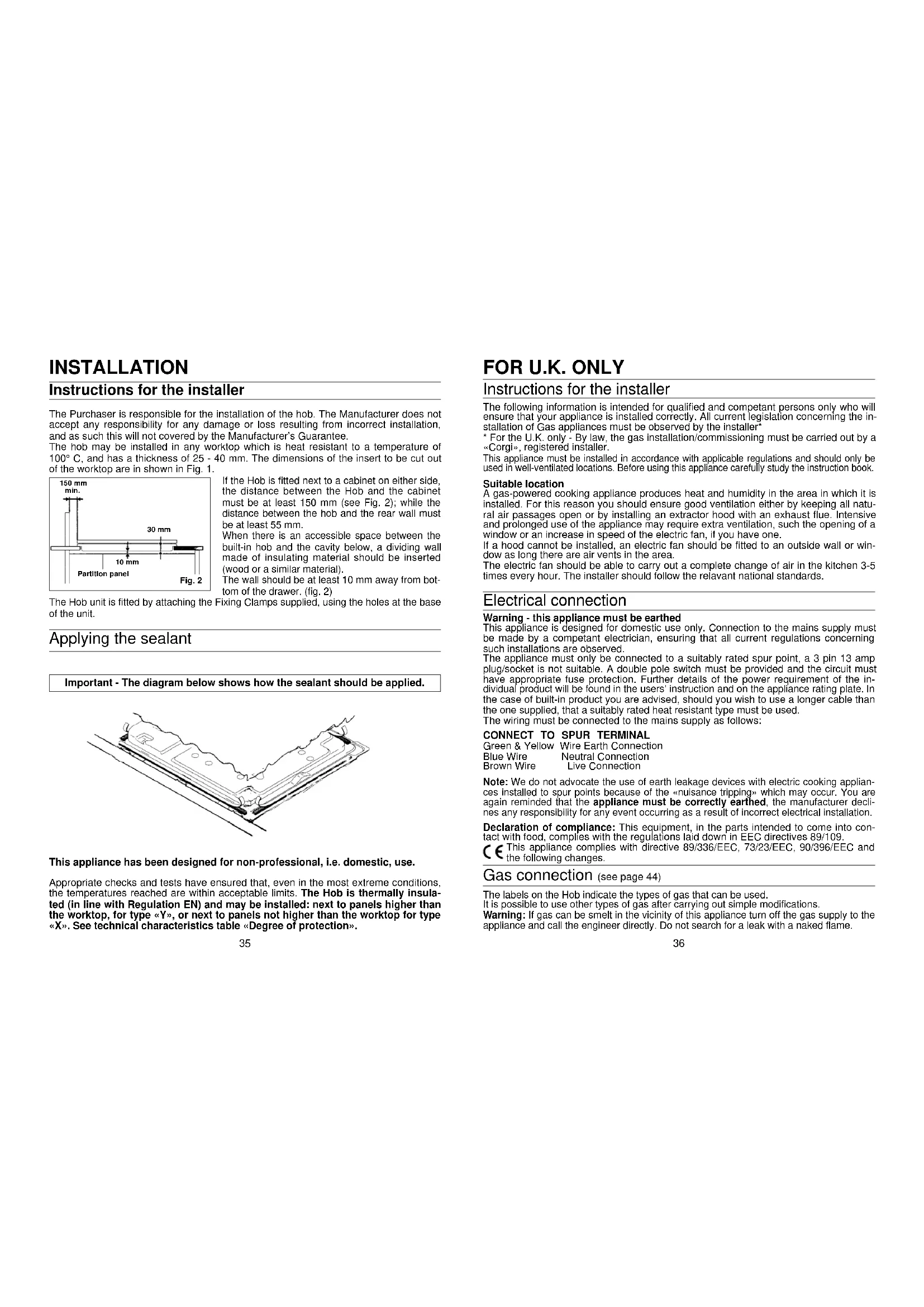
- Some models only ** Manufacturer setting IE cat. II2H3 + GB cat. II2H3 + Cooking hobs 60x50 A A B B C C D D Burners 4 gas 4 gas 3 gas 3 gas 4 gas 4 gas 4 gas 4 gas – – 1 electric 1 electric –––– Reference type PL01 PL02 PL01 PL02 PL01 PL02 PL01 PL02 Supply Voltage (V/Hz) 230/50 230/50 230/50 230/50 230/50 230/50 230/50 230/50 Installed electric power (W) – – 1400 1400 –––– Medium burner 1 1 ––1111Large back burner 1 1 111111Small burner 1 1 111111Large front burner 1 1 11––––Double ring burner – – ––––11Maxi burner – – ––11––Power of gas installed: - G20/20 mbar (kW)** 8,2 8,2 6,7 6,7 8,6 8,6 8,6 8,6 - G30/28-30 mbar (g/h) 597 597 488 488 620 620 620 620 Electric ignition* yes yes yes yes yes yes yes yes Gas safety device – yes – yes – yes – yes Product size mm. 595x510 595x510 595x510 595x510 595x510 595x510 595x510 595x510 Degree protection – – Type Y Type Y –––– Class 3 3 333333Fig. 1Fig. 1bMD LDR S MD LLS LS MD L MS3635 INSTALLATION Instructions for the installer The Purchaser is responsible for the installation of the hob. The Manufacturer does notaccept any responsibility for any damage or loss resulting from incorrect installation,and as such this will not covered by the Manufacturer’s Guarantee.The hob may be installed in any worktop which is heat resistant to a temperature of100° C, and has a thickness of 25 - 40 mm. The dimensions of the insert to be cut outof the worktop are in shown in Fig. 1.If the Hob is fitted next to a cabinet on either side,the distance between the Hob and the cabinetmust be at least 150 mm (see Fig. 2); while thedistance between the hob and the rear wall mustbe at least 55 mm. When there is an accessible space between thebuilt-in hob and the cavity below, a dividing wallmade of insulating material should be inserted(wood or a similar material).The wall should be at least 10 mm away from bot-tom of the drawer. (fig. 2)The Hob unit is fitted by attaching the Fixing Clamps supplied, using the holes at the baseof the unit. Applying the sealant Important - The diagram below shows how the sealant should be applied. This appliance has been designed for non-professional, i.e. domestic, use. Appropriate checks and tests have ensured that, even in the most extreme conditions, the temperatures reached are within acceptable limits. The Hob is thermally insula- ted (in line with Regulation EN) and may be installed: next to panels higher than the worktop, for type «Y», or next to panels not higher than the worktop for type «X». See technical characteristics table «Degree of protection». Fig. 2Partition panel150 mm min. 30 mm10 mm Instructions for the installer The following information is intended for qualified and competant persons only who willensure that your appliance is installed correctly. All current legislation concerning the in-stallation of Gas appliances must be observed by the installer* * For the U.K. only - By law, the gas installation/commissioning must be carried out by a«Corgi», registered installer. This appliance must be installed in accordance with applicable regulations and should only beused in well-ventilated locations. Before using this appliance carefully study the instruction book. Suitable locationA gas-powered cooking appliance produces heat and humidity in the area in which it isinstalled. For this reason you should ensure good ventilation either by keeping all natu-ral air passages open or by installing an extractor hood with an exhaust flue. Intensiveand prolonged use of the appliance may require extra ventilation, such the opening of awindow or an increase in speed of the electric fan, if you have one.If a hood cannot be installed, an electric fan should be fitted to an outside wall or win-dow as long there are air vents in the area.The electric fan should be able to carry out a complete change of air in the kitchen 3-5times every hour. The installer should follow the relavant national standards. Electrical connection Warning - this appliance must be earthedThis appliance is designed for domestic use only. Connection to the mains supply mustbe made by a competant electrician, ensuring that all current regulations concerningsuch installations are observed. The appliance must only be connected to a suitably rated spur point, a 3 pin 13 ampplug/socket is not suitable. A double pole switch must be provided and the circuit musthave appropriate fuse protection. Further details of the power requirement of the in-dividual product will be found in the users’ instruction and on the appliance rating plate. the case of built-in product you are advised, should you wish to use a longer cable thanthe one supplied, that a suitably rated heat resistant type must be used.The wiring must be connected to the mains supply as follows:CONNECT TO SPUR TERMINALGreen & Yellow Wire Earth ConnectionBlue Wire Neutral ConnectionBrown Wire Live Connection Note: We do not advocate the use of earth leakage devices with electric cooking applian- ces installed to spur points because of the «nuisance tripping» which may occur. You areagain reminded that the appliance must be correctly earthed, the manufacturer decli-nes any responsibility for any event occurring as a result of incorrect electrical installation. Declaration of compliance: This equipment, in the parts intended to come into con- tact with food, complies with the regulations laid down in EEC directives 89/109. This appliance complies with directive 89/336/EEC, 73/23/EEC, 90/396/EEC andthe following changes. Gas connection (see page 44) The labels on the Hob indicate the types of gas that can be used.It is possible to use other types of gas after carrying out simple modifications.
Warning: If gas can be smelt in the vicinity of this appliance turn off the gas supply to the
appliance and call the engineer directly. Do not search for a leak with a naked flame.
Adapting the hob to different types of gas To adapt the Hob for use with different types of gas, carry out the following instructions: — remove the grids and burners — insert the hexagonal spanner (supplied) into the burner support (Fig. 5) — unscrew the injector and replace it with one suitable for the gas to be used (see Table of gas consumption) — carry out regulation of the burner.
Electrical connection Check the data on the rating plate, located on the outside of the unit, to ensure that the supply and input voltage are suitable. Before connection, check the earthing system. By Law, this appliance must be earthed. If this regulation is not complied with, the Manufacturer will not be responsible for any damage caused to persons or property. If a plug is not already attached, fit a plug appropriate to the load indicated on the rating plate. The earth wire is coloured yellow/green. The plug should always be accessible. Where the Hob is connected direct to the electricity supply, a circuit breaker must be fitted with at least a 3 mm contact spacing when in the open position. It if is necessary to replace the connecting cable, the earth wire (yellow/green) must, by law, be approximately 10 mm longer than the live and neutral wires. Rubber insulat- ed cable type H05RR-F must be used. The cables should be 1 mm
section, also, the maximum external diameter of the ca- ble should not be greater than 7 mm. The rating plate on the hob shows the type of gas with which it is designed to be used. It is possible to use other types of gas after carrying out some simple modifications. (See the instructions in the following paragraphs). a) Connection to the gas supply — connection to the mains gas supply or gas cylinder should be carried out according to the relevant national standards, after having checked that it is regulated for the type of gas with which it will be supplied. If it is not correctly regulated follow the instructions in the paragraph entitlet «Adaption for different types of gas». For liquid gas (cylinder gas) use pressure regulators which comply with the relevant national standards. N.B.: for safe operation, economic use of energy and to ensure greater durability of the appliance, make sure that the supply pressure conforms with the values shown in the table on page 38 — Connection to a rigid pipe (see instruction on page 44) Connection to the gas supply should be done without putting any kind of stress on the appliance. — Connection to a flexible steel pipe (see instructions on page 44) The junction of the gas pipe with the appliance is a 1/2” gas tapered thread connec- tion. Use only pipes, washers and sealing washers which comply with the relevant national standards. The fitting of these pipes should be done to that their maximum length, when fully extended, should not exceed 2000 mm. N.B.: carry out a final check for leaks on the pipework using a soapy solution. Never use a flame. Also, make sure that the flexible pipe cannot come into contact with a movlng part of the cabinet (eg, a drawer) and that it is not situa- ted where it could be damaged. Gas connection Hexagonal spannerFig. 5 LIVE L EARTH NEUTRAL N MAINS SUPPLY
BROWN WIREGREEN/YELLOW WIREBLUE WIREPOWERCABLE
Regulating the burners For maximum efficiency from the burners, the correct combustion of the flame is neces- sary (see table of gas consumptions quota “X”). A good flame must be well aligned and without yellow tips (Fig. 7/B). If there is insufficient air, the flame will be uneven with yel- low tips (Fig. 7/A). If there is too much air, the flame will be very short and bright (Fig. 7/C). In these cases the combustion must be adjusted by re-fitting the carburation tube to the Venturi (where there is insuffi- cient air) or removing the carburation tube (in the case of too much air). To position the carburation tube, the fixing screws must be loosened, and retightened when the sati- sfactory combustion is obtained. air regul. 4mm 4mm 2mm 6mm 15 mm13 mmWorkingburnerlarge back rightlarge front leftmediumsmalldouble ring maxi Ø injector1/100 mm
Qmin. 0,6500,6500,3800,2800,9000,900 air regul. 4mm 4mm 2mm 6mm 13 mm13 mm air regul. 2mm 2mm 5mm 4mm 0 mm 0 mm G20 G30 G25 G31G30G20/G25 G20/G30 G25Quota «X» dependingon type of gasTable of gas consumption 1W = 0,860 kcal/h air regul. 5mm 5mm 7mm 6mm 15 mm13 mm40 Regulating the minimum flame After lighting the burners, turn the control knob to the minimum setting and then remo-ve the knob (this can easily be removed by apply a gentle pressure). Using a small «Terminal» type screwdriver the regulating screw can be adjusted as inFig. 8. Turning the screw clockwise reduces the gas flow, whilst turning it anticlockwiseincreases the flow – Use this adjustment to obtain a flame of approximately 3 to 4 mmin length and then replace the control knob. If GPL (cylinder) gas is being used, turn the screw clockwise right to the end of thetravel of the by-pass. Screws regulating (for differend models) ATTENTION: When cleaning the hob, take care to replace the burners correctly,this will ensure that the ignition point is not blocked.GENERAL ADVICEFor the best results, the flat-bottomed pans size should match the gas burner size asfollows: — Front right burner from 6 to 12 cm.— Front left burner from 24 to 26 cm.— Back left burner from 12 to 18 cm.— Back right burner from 18 to 24 cm.See fig. 1b pag. 34.For smaller containers the gas burner should be regulated so that the flame does notoverlap the base of the pan. Vessels with concave or convex base should not be used. WARNING: If a burner is accidentally extinguehed, turn the knob to the off posi-tion and do not attempt to re-ignite if for at least 1 minute. To protect the glass lid from damage and in the interests of safety, the burners/platesmust be turned off and the burner/pan support/plate area must be cool before closingthe lid down. Use of electric hotplates (electric hotplates) For the best use of the electric hotplates and to minimise energy consumption, the fol-lowing recommendations should be noted.
User instructions This appliance must only be used for the purpose for which it is intended, domesticcooking, and any other use will be considered improper and could therefore be danger-ous. The Manufacturer will not be responisble for any damage or loss resulting fromimproper use. Using the gas Burner To ignite the burners, place a lighted taper close to the burner, press in and turn thecontrol knob anti-clockwise. If the burners have not been used for a couple of days, wait for a few seconds beforelighting the burner, this will allow any air present in the pipes to escape.For appliances fitted with electronic ignition carry out the following:• push in and turn the knob anticlockwise to the symbol.• ignite the burner by pressing the sparker button.For hobs fitted with automatic ignition simply push in and turn the knob to the
sym- bol. The ignition generator is a repetitive discharge type.If the burner is not ignited within 5 seconds, turn the knob to the 0 position and repeatthe operation.For models fitted with a safety tap (which cuts-off the flow of gas if the flame is acci-dentally extinguished) the burners are ignited ad described above, but care must be taken to keep the knob pressed in for 5 or 6 seconds after the flame is ignited.
Fig. 6 Fig. 7BURNER CAPBURNERAIR REGULATIONSCREWFIXINGSCREWSMALLMEDIUMLARGEDOUBLE RING MAXI For dimensions «X» see table of gas consumptionWhen you have carried out the new gas regulation, replace the old gas rating pla-te on your appliance with one (supplied with hob) suitable for the type of gas forwhich it has been regulated. Lubricating the gas taps If a gas tap becomes stiff, it should be dismantled, cleaned carefully with petrol andsmeared with a drop of special heat resistant grease. The following operations should be carried but:— disconnect the electrical power supply, close the gas supply tap from the mains orcylinder. — Remove the knobs and the plate by removing the screws located at the rear of theplate itself and beneath the individual burners.— Remove the two screws holding down the head flange.— Remove the head flange and the retaining spring on the knob shaft.— Remove the gas regulation cone, clean it with petrol and smear it with some heatresistant grease, taking care not to obstruct any holes through which gas must pass.— Re-assemble all the parts, making sure that the spring and the rotating axis of thecone fitted to the knob shaft are correctly seated. Fig. 8Maintenance and cleaning Before cleaning the Hob, ensure the appliance has cooled down. Remove the plug from the socket or (if connected directly) switch off the electricity supply. When cleaning the enamelled, varnished or chrome sections, use warm soapy water or a non caustic detergent. For stainless steel use an appropriate cleaning solution. Hotplates should only be cleaned with a cotton cloth coated with vaseline or seed oil. Never use abrasives, corrosive detergents, bleaching agents or acids. Avoid any acid or alkaline substances (lemon, juice, vinegar etc.) on the enamelled, varnisched or stain- less steel sections. The burners can be cleaned with soapy water. To restore their original shine, use a household stainless steel cleaner. After cleaning, dry the burners and replace. It is important the Burners are replaced correctly.
Only pans which have smooth flat bases should be used on the electric hotplates. The size of the pan should be as close as possible to the diameter of the hotplate, and ne- ver smaller (see Fig. 9). The base of the pan should be dry and spillages should be avoided. Empty pans should not be left on the plates, nor should the plates left switched on without a pan. A neon indicator light adjacent to the control knob will glow when the electric plate is in use. POWER OUTPUT - ELECTRIC HOTPLATESSetting0 OFF1 VERY LOW Warming dishes & melting butter and chocolate2 LOW Simmering, sauces, stews, milk puddings, poached eggs3 MODERATE Vegetables, frozen foods, boiling water4 MEDIUM Fresh Vegetables, pasta, fish, pancakes.5 HIGH Omelettes, steaks6 VERY HIGH Chops
Aftercare Before calling out a Service Engineer please check the following: — that the plug is correctly inserted and fused; — that the gas supply is not faulty. If the fault cannot be identified: switch off the appliance — do not tamper with it — call the Aftercare Service Centre. The appliance is supplied with a guarantee certificate that ensures that it will be re- paired free of charge at the Service Centre. Cover The cover is available as optional accessory. The Manufacturer will not be responsible for any inaccuracy resulting from printing or transcript errors con- tained in this brochure. We reserve the right to carry out modifications to products as required, including the interests of consumption, without prejiudice to the characteristics relating to safety or function. Before closing the cover, to protect it from excessive temperature changes, always wait until the burners or plates have completely cooled down. Any spillages should be removed from the cover before opening it. Chromed grids and burners Chromed grids and burners have the tendency to dark with the use. This is a normal and inevitable phenomenon, but it doesn’t jeopardize absolutely the functionality of the hob. In anycase from our after sales service centre the spare parts are available.INSTRUCTIONS FOR ASSEMBLY OF THE HOB
TO THE GAS SUPPLY PIPES
These instructions are for Fitters qualified for installation of equipment in line with therelevant national standard. All work must be carried out with the electricity supply dis-connected. ASSEMBLY PROCEDURE 2 Spanners, sizes 17 and 23 mm are required. 1/2 GAS CONICAL A) As illustrated, as-semble parts in se-quence: A) fixed pipe B) washer C) Elbow fitting withtapered thred connection2) Tighten the jointswith the Spanners, remembering to twistthe pipes into positionbefore tightening.3) Attach fitting C tomains gas supply us-ing rigid copper pipeor flexible steel pipe.
VERY IMPORTANT For ease of installation and to avoid gas leaks, it is recommended to con-nect the pipes as follows: First connect the pipe to the Hob and then Connect the pipe to the gas supply.In this sequence is not followed, there is a danger that gas will be trappedin the pipe.AFTER INSTALLATION, CHECK THE TIGHTNESS OF ALL JOINTS USINGA SOAPY SOLUTIONPlease noteSome models are equipped with both conical and cylindrical connectors for gas supply.Please select the type which is correct for the supply concerned.Cylindrical(but connector)Taperedthread conical