FSH 775 G DWK XX - Cooker Fulgor Milano - Free user manual and instructions
Find the device manual for free FSH 775 G DWK XX Fulgor Milano in PDF.
Download the instructions for your Cooker in PDF format for free! Find your manual FSH 775 G DWK XX - Fulgor Milano and take your electronic device back in hand. On this page are published all the documents necessary for the use of your device. FSH 775 G DWK XX by Fulgor Milano.
USER MANUAL FSH 775 G DWK XX Fulgor Milano
Index Instructionsfor use Installation, 12 Use, 12 Maintenance, 13 Instructions for the installater Installation, 15 Gas connection, 15 Electrical connection, 15 User characteristics, 17 THIS APPLIANCE IS CONCEIVED FOR DOMESTIC USE ONLY. THE MANUFACTURER SHALL NOT IN ANY WAY BE HELD RESPONSIBLE FOR WHATEVER INJURIES OR DAMAGES ARE CAUSED BY INCORRECT INSTALLATION OR BY UNSUITABLE, WRONG OR ABSURD USE. THIS APPLIANCE IS NOT INTENDED FOR USE BY PERSONS (INCLUDING CHILDREN) WITH REDUCED PHYSICAL, SENSORY OR MENTAL CAPABILITIES, OR LACK OF EXPERIENCE AND KNOWLEDGE, UNLESS THEY HAVE BEEN GIVEN SUPERVISION OR INSTRUCTION CONCERNING USE OF THE APPLIANCE BY A PERSON RESPONSIBLE FOR THEIR SAFETY.CHILDREN SHOULD BE SUPERVISED TO ENSURE THAT THEY DO NOT PLAY WITH THE APPLIANCE. Dear customer, We thank you and congratulate you on your choice. This new carefully designed product, manufactured with the highest quality materials, has been carefully tested to satisfy all your cooking demands. We would therefore request you to read and follow these easy instructions which will allow you to obtain excellent results right from the start. May we wish you all the very best with your modern appliance! THE MANUFACTURER Italiano
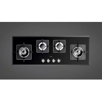
Installation All the operations concerned with the installation (electrical and gas connections, adaptation to type of gas, necessary adjustments, etc.) must be carried out by qualified technicians, in terms with the standards in force. For specific instructions, kindly read the part reserved for the installation technician. Use Use Gas burners (Fig. 1-3)The ignition of the gas burner is carried out by putting a small flame to the upper part holes of the burner, pressing and rotating the corresponding knob in an anti-clockwise manner, until the maximum position has coincided with the marker. When the gas burner has been turned on, adjust the flame according to need. The minimum position is found at the end of the anti-clockwise rotation direction. For models with automatic/ simultaneous (with one hand) ignition, it is sufficient to proceed as described above using the corresponding knob. The electric spark between the ignition plug and the burner provides the ignition of the burner itself. After ignition, immediately release the push-button and adjust the flame according to need. For models with a thermoelectric safety system, the burner is ignited as in the various cases described above, keeping the knob fully pressed on the maximum position for approximately 3/5 seconds. After releasing the knob, make sure the burner is actually lit. N.B. - We recommend the use of pots and pans with a diameter matching that of the burner, thus preventing the flame from escaping from the bottom part and surrounding the pot;- do not leave any empty pots or pans on the fire;- do not use any tools for grill-cooking on Crystal hobs. When cooking is finished, it is also a good norm to close the main gas pipe tap and/or cylinder. DWK modelsModels SH 775 G DWK, SH 905 G DWK and SH 1124 G 2DWK have a Dual Wok burner. The centre flame (F1) can be lit by pressing the knob and turning it clockwise or the entire burner (F2) can be lit as shown in the figure below. Important GAS PROTEKT On floors with thermoelectric protection (Gas Protekt do not keep the ignite button pushed for more than 15 seconds. If the burner has not ignited after 15 seconds, open the door of the room and wait at least one minute before making a further attempt.wok Ø 20-32fast Ø 20-26semifast Ø 14-20auxiliary* Ø 10-14*with reduction grid GAS Fig. 1 Instructions for use
Maintenance Gas/Electrical Prior to any operation, disconnect the appliance from the electrical system. For long-life to the equipment, a general cleaning operation must take place periodically, bearing in mind the following:
- the glass, steel and/or enamelled parts must be cleaned with suitable non-abrasive or corrosive products (found on the market). Avoid chlorine-base products (bleach, etc.);
- avoid leaving acid or alkaline substances on the working area (vinegar, salt, lemonjuice, etc.);
- the wall baffle and the small covers (mobile parts of the burner) must be washed frequently with boiling water and detergent, taking care to remove every possible encrustation. Dry carefully and check that none of the burner holes is fully or partially clogged;
- the electrical parts are cleaned with a damp cloth and are lightly greased with lubricating oil when still warm;
- the stainless steel grids of the working area, after having been heated, take on a bluish tint which does not deteriorate the quality. To bring colour back to its original state, use as lightly abrasive product. N.B.- Cleaning of the taps must be carried out by qualified personnel, who must be consulted in case of any functioning anomaly. Check periodically the state of conservation of the flexible gas feed pipe. In case of leakage, call immediately the qualified technicians for its replacement.
Installation This appliance is not provided with a combustion product discharge. It is recommended that it be installed insufficiently aerated places, in terms of the laws in force. The quantity of air which is necessary for combustion must not be below 2.0 m
/h for each kW of installed power. See table of burner power. Positioning (Fig. 4) The appliance can be fitted into a working area as illustrated on the corresponding figure. Before positioning the hob, fit the seal around the entire periphery of the hole cut in the worktop. Fig. 4 Gas connection (Fig. 5) Connect the appliance to the gas cylinder or to the installation according to the prescribed standards in force, and ensure beforehand, that the appliance matches the type of gas available. Other wise, see ”Adaptation to various types of gas”. Further more, check that the feed pressure fall swithin the values described on the table: ”User chacteristics”. Fig. 5 Rigid/semi rigid metalconnection Carry out the connection with fittings and metal pipes (even flexible pipes) so as to obtain counter stress the inner parts of the appliance. N.B. - when the installation has been carried out, check the perfect sealing of the entire connection system, by using a soapy solution. Electrical connection (Fig. 6) Prior to carrying out the electrical connection, please ensure that:
- the plant characteristics are such as to follow what is indicated on the matrix plate placed at the bottom of the working area;
- that the plant is fitted with an efficient earth connection, following the standards and law provisions in force. The earth connectionis compulsory in terms of the law. Should there be no cable and/or plug on the equipment, use suitable absorption material for the working temperature as well, as indicated on the matrix plate. Under no circumstance must the cable reach a temperature above 50°C of the ambient temperature. If connecting directly to the mains power supply, fit a multi-pole switch of a suitable size for the rated capacity with a clearance distance which completely disconnects the power line under overvoltage category III conditions, consistently with the rules of installation (the yellow/ green earth wir must not be interrupted). The plug or omnipolar switch must be easily reached on the installed equipment. Fig. 6 To avoid all risk, if the power cable becomes damaged, it must only be replaced by the manufacturer, by an authorised service centre, or by a qualified electrician. Instructions for the installer
Adaptation to varius types of gas (Fig. 7) Should the appliance be pre-set for a different type of gas than available, procreed as follows:
- replace the injector (Fig. 7) with the corresponding type of gas to be used (see table “User characteristics“);
- to adjust to the minimum, use a screwdriver on the screw placed on the tap (Fig. 8) after turning the tap to its minimum position. For GPL (butane/propane) screw tight.