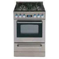
DGR24P3S - Cooker Avanti - Free user manual and instructions
Find the device manual for free DGR24P3S Avanti in PDF.


| Product Type | Gas Range |
| Brand | Avanti |
| Model | DGR24P3S |
| Power Supply | 115 V ~ 60 Hz, grounded outlet |
| Gas Type | Natural gas (NG) or propane (LP) - conversion kit included |
| Surface Burners | 4 burners: 1 auxiliary, 2 semi-rapid, 1 rapid |
| Burner Power (natural gas) | Auxiliary: 0.8 kW; Semi-rapid: 1.0 kW; Rapid: 1.4 kW |
| Oven | Bottom oven burner, top broiler burner |
| Maximum Oven Temperature | 500 °F (260 °C) |
| Oven Functions | Traditional baking, broiling, rotisserie (with spit), interior light |
| Controls | Rotary knobs with integrated electronic ignition, digital clock/timer |
| Safety | Anti-tip device, flame detection on burners, oven/broiler safety valve |
| Supplied Accessories | Backsplash, oven racks (2), drip pan, rotisserie rack (model DGR24P3S), propane conversion kit, anti-tip bracket |
| Maintenance and Cleaning | Clean with soapy water, avoid abrasive products; do not use steam cleaner |
| Installation | Must be installed by a qualified professional; comply with local and national codes |
| Customer Service | Avanti Products: 800-220-5570 (parts); 800-323-5029 (product info) |
Frequently Asked Questions - DGR24P3S Avanti
User questions about DGR24P3S Avanti
0 question about this device. Answer the ones you know or ask your own.
Ask a new question about this device
Download the instructions for your Cooker in PDF format for free! Find your manual DGR24P3S - Avanti and take your electronic device back in hand. On this page are published all the documents necessary for the use of your device. DGR24P3S by Avanti.
USER MANUAL DGR24P3S Avanti
When using the cooktop, press the knob all the way in, turn to ignite the flame and hold for approximately 10 seconds to allow the system to heat to the appropriate temperature and allow the flow of gas to the selected burner.

INSTRUCTION MANUAL MANUAL DE INSTRUCCIONES MANUEL D'INSTRUCTIONS
20" WIDE 24" WIDE
Avanti Products has a policy of continuous improvement on its products and reserves the right to change materials and specifications without notice.
Avanti Products LLC
P.O. Box 520604 - Miami, Florida 33152
www.avantiproducts.com
TABLE OF CONTENTS
| Range Safety | 3 |
| Important Safe guides | 4 |
| The Anti-tip Bracket | 5 |
| Help Us Help You ... | 6 |
| Parts and Features | 7 - 8 |
| Before Using Your Gas Range | 9 |
| Important Precautions and Recommendations | 10 - 13 |
| How to use the top burners | 14 - 15 |
| How to use the Gas oven / Rotisserie (DGR24P3S - ONLY) | 15 - 19 |
| Oven light | 19 |
| Care and Maintenance | 20 - 23 |
| Troubleshooting Guide | 24 - 25 |
| Wiring Diagram | 25 |
| Service for Your Appliance | 25 |
| Your Avanti Products Warranty | 26 |
| Instrucciones en Español | 27 - 47 |
| Instructions en Français | 48 - 73 |
| Registration Information and Registration Card | Last Page |
RANGE SAFETY
Your safety and the safety of others are very important.
We have provided many important safety messages in this manual and on your appliance. Always read and obey all safety messages.

This is the Safety Alert Symbol.
This symbol alerts you to potential hazards that can kill or injure you and others. All safety messages will follow the Safety Alert Symbol and either the words "DANGER", "WARNING" or "CAUTION". These words mean:

Danger means that failure to heed this safety statement may result in severe personal injury or death.

Warning means that failure to heed this safety statement may result in extensive product damage, serious personal injury, or death.
CAUTION
Caution means that failure to heed this safety statement may result in minor or moderate personal injury, or property or equipment damage.
All safety messages will alert you what the potential hazard is, tell you how to reduce the chance of injury, and let you know what can happen if the instructions are not followed.
IN THE COMMONWEALTH OF MASSACHUSETTS
• This product must be installed by a licensed plumber or gas fitter.
- When using ball-type gas shut-off valves, they shall be the T-handle type.
- A flexible gas connector, when used, must not exceed 3 feet in length.
BEFORE YOU BEGIN!
Installation of this range must conform with all local codes, or in the absence of local codes, with the National Fuel Gas Code, ANSI Z223.1 / NFPA.54, latest edition. In Canada, installation code, CAN/CGA-B149.1 or the current Propane installation code, CAN/CGA-B149.2, and with local codes where applicable.
BEFORE INSTALLATION
DO NOT use an air curtain or other overhead range hood, which operates by blowing a downward airflow onto a range, in conjunction with a gas range unless the hood and range have been designed and tested and listed by an independent laboratory in accordance with the Standard for Domestic Gas Ranges, ANSI Z21.1 • CSA 1.1 for combination use. The installation instructions for both the gas range and air curtain range hood shall include statements that the air curtain or overhead range hood is permitted to be used in conjunction with a gas range, and that both unit have been designed and tested in accordance with the Standard for Domestic Gas Ranges, ANSI Z21.1 • CSA 1.1 for combination use. Purchaser / Installer should review the installation instructions for each unit to ensure their range is acceptable for use with such ventilation system.
Installation in Manufactured (Mobile) Homes:
The installation must conform with the Manufactured Home Construction and Safety standard, Title 24 CFR, Part 3280 [formerly the Federal Standard for Mobile Home Construction and Safety, Title 24, HUD (Part 280)] or, when such standard is not applicable, the Standard for Manufactured Home Installations, ANSI/NCSBCS A225.1, or with local codes where applicable.
IMPORTANT SAFE GUIDES

Before the appliance is used, it must be properly positioned and installed as described in this manual, so read the manual carefully. To reduce the risk of fire, electrical shock or injury when using the appliance, follow basic precaution, including the following:

DANGER

•
- It is recommended that a separate circuit, serving only your appliance be provided. Use receptacles that cannot be turned off by a switch or pull chain.
- Never clean appliance parts with flammable fluids. These fumes can create a fire hazard or explosion. And do not store or use gasoline or other flammable vapors and liquids in the vicinity of this or any other appliance. The fumes can create a fire hazard or explosion.
- Before proceeding with cleaning and maintenance operations, make sure the power line of the unit is disconnected.
- Unplug the appliance or disconnect power before cleaning or servicing. Failure to do so can result in electrical shock or death.
- Do not attempt to repair or replace any part of your appliance unless it is specifically recommended in this manual. All other servicing should be referred to a qualified technician.

WARNING

WARNING: If the information in this manual is not followed exactly, a fire or explosion may result causing property damage, personal injury or death.
- This appliance shall not be used for space heating. The surface unit should not be operated without cookware. This information is based on safety considerations.
- All openings in the wall behind the appliance and in the floor under the appliance shall be sealed.
- Keep appliance area clear and free from combustible materials, gasoline, and other flammable vapors.
- Do not obstruct the flow of ventilation air.
- Disconnect the electrical supply to the appliance before servicing.
- When removing appliance for cleaning and/or service:
• Disconnect AC power supply.
- Carefully remove the range by pulling outward.
CAUTION: Range is heavy. Use care in handling.
- The misuse of oven door (e.g. stepping, sitting, or leaning on them) can result in potential hazards and /or injuries.
- When installing or removing the range for service, a rolling life jack should be used. Do not push against any of the edges of the range in an attempt to slide it into or out of the installation. Pushing or pulling a range (rather than using a lift jack) also increases the possibility of bending the leg spindles or the internal coupling connectors.
- It is important for the appliance to be leveled in order to work properly. You may need to make several adjustments to level it.
- Never allow children to operate, play with or crawl inside the appliance.
- Electrical Grounding Instructions - The appliance must be installed and grounded by a qualified technician in accordance with the National Electrical Code ANSI/NFPA No. 70 (Latest Edition) and local electrical code requirements.
- Replacement Parts – Only authorized replacement parts may be used in performing service on the range. Replacement parts are available from factory authorized parts distributors. Contact the nearest Avanti service center in your area.
THE ANTI-TIP BRACKET
The range will not tip during normal use. However, the range can tip if you apply too much force or weight to the open door without the anti-tip bracket fastened down properly.
To reduce the risk of tipping the appliance, the appliance must be secured by properly installed anti-tip devices packed with the appliance.
 | WARNING |
 | ALL RANGES CAN TIPINJURY TO PERSON COULD RESULTINSTALL ANTI-TIP DEVICE PACKED WITH RANGESEE INSTALLATION INSTRUCTIONS |
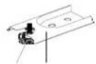 Range Foot Anti-tip Bracket Range Foot Anti-tip Bracket | Making sure the anti-tip bracket is installed:Slide range forward.Look for the anti-tip bracket securely attached to floor.Slide range back so rear range foot is under anti-tip bracket. |
WARNING: IF THE INFORMATION IN THIS MANUAL IS NOT FOLLOWED EXACTLY, A FIRE OR EXPLOSION MAY RESULT CAUSING PROPERTY DAMAGE, PERSONAL INJURY, OR DEATH.
√ Do not store or use gasoline or other flammable vapors and liquids in the vicinity of this or any other appliance.
√ WHAT TO DO IF YOU SMELL GAS:
- Do not try to light any appliance.
- Do not touch any electrical switch; do not use any phone in your building.
- Immediately call your gas supplier from a neighbor's phone. Follow the gas supplier's instructions.
- If you cannot reach your gas supplier, call the fire department.
√ Installation and service must be performed by a qualified installer, service agency, or the gas supplier.
HELP US HELP YOU...
Read this guide carefully.
It is intended to help you operate and maintain your new Gas Range properly.
Keep it handy to answer your questions. If you don't understand something or you need more assistance, please call:
Avanti Customer Service 800-220-5570
Keep proof of original purchase date (such as your sales slip) with this guide to establish the warranty period.
Write down the model and serial numbers.
You'll find them on a plate located on the front bottom wall of the Gas Range.
Please write these numbers here:
Date of Purchase
Model Number
Serial Number
Use these numbers in any correspondence or service calls concerning your Gas Range.
If you received a damaged Gas Range, immediately contact the dealer (or builder) that sold you the Gas Range.
Save time and money. Before you call for service, check the Troubleshooting Guide. It lists causes of minor operating problems that you can correct yourself.
IF YOU NEED SERVICE
We're proud of our service and want you to be pleased. If for some reason you are not happy with the service you receive, here are some steps to follow for further assistance.
FIRST, contact the people who serviced your Gas Range. Explain why you are not pleased. In most cases, this will solve the problem.
NEXT, if you are still not pleased, write all the details, including your telephone number, and send it to:
Customer Service
Avanti Products
10880 NW 30 Street
Miami, FL 33172
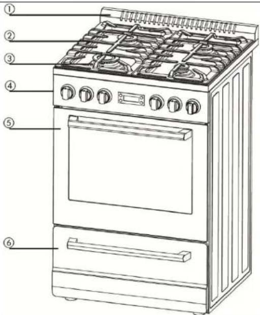
PARTS & FEATURES
| Model: DGR20P3S | Model: DGR24P3S | ||
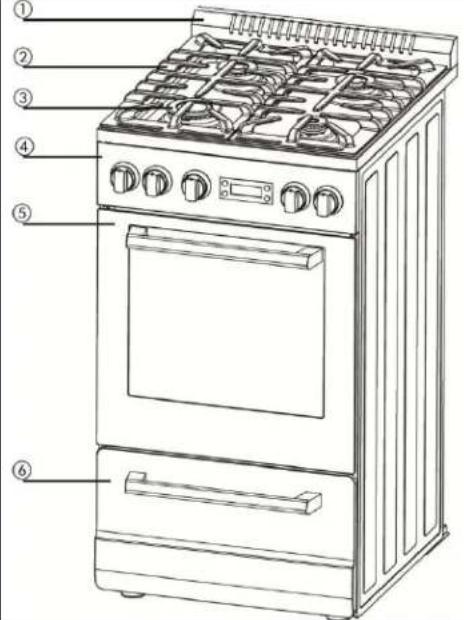 | 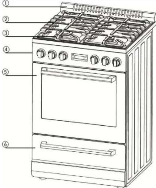 | ||
| 1 | Backsplash / Oven Vent | 1 | Backsplash / Oven Vent |
| 2 | Cast Iron Pan Supports 2 Cast Iron Pan Supports | Pan Supports | |
| 3 | Sealed Burners (Total 4) 3 Sealed Burners (Total 4) | Burners | |
| 4 | Control Panel with Digital Clock 4 Control Panel with Digital Clock | Control Panel with Digital Clock | |
| 5 | Oven Door with Handle 5 Oven Door with Handle | with Handle | |
| 6 | Storage Drawer with Handle 6 Storage | Drawer with Handle | |
Digital Clock / Timer
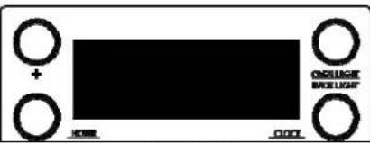 | 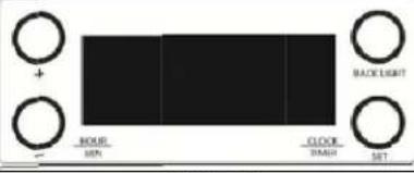 |
| DGR20P3S | DGR24P3S |
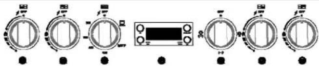
CONTROL PANEL
| 1 | Front Left Burner Control Knob | 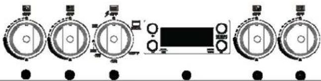 MODEL # DGR20P3S MODEL # DGR20P3S |
| 2 | Rear Left Burner Control Knob | |
| 3 | Oven Tem perature Control Knob | |
| 4 | Digital Timer and Clock | |
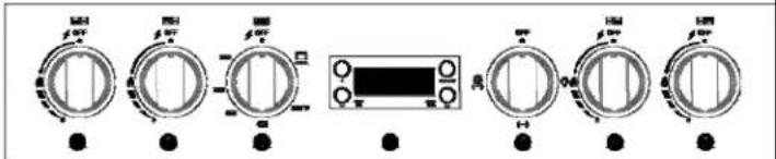
| 5 | Lamp / Rotisserie Control Knob | |
| 6 | Front Right Burner Control Knob | |
| 7 | Rear Right Burner Control Knob | |
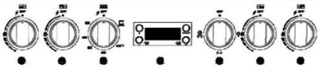 MODEL # DGR24P3S MODEL # DGR24P3S | ||
| 1 | Front Left Burner Control Knob | |
| 2 | Rear Left Burner Control Knob | |
| 3 | Oven Tem perature Control Knob | |
| 4 | Digital Timer and Clock | |
| 5 | Lamp / Rotisserie Control Knob | |
| 6 | Front Right Burner Control Knob | |
| 7 | Rear Right Burner Control Knob | |
COOKTOP
| BTU/hr Ratings | |||
| 20” | 24” | ||
| 1 | Auxiliary 2500 | 2500 | |
| 2 | Right Semi-rapid | 4300 | 4300 |
| 3 | Left Semi-rapid | 4300 | 4300 |
| 4 | Rapid 8000 | 8000 | |
Note:
-The electric gas-lighting device is incorporated into the knobs.
CAUTION:
If the burner is accidentally extinguished, turn the gas off at the control knob and wait at least 1 minute before attempting to relight.
CAUTION:
Gas appliances produce heat and humidity in the environment in which they are installed.
Ensure that the cooking area is well ventilated following national/local codes.
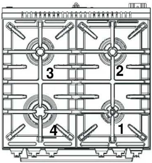
Note:
Line drawing above may vary from your actual unit.

Digital Kitchen Timer
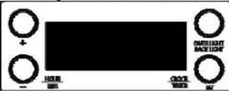
Model #: DGR20P3S
Digital
Display Up (+)
Button Down
(-) Button Set
Button
Back Light ON/OFF Button
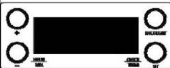
Model #: DGR24P3S
Digital
Display Up (+)
Button Down
(-) Button Set
Button
Back Light ON/OFF Button
When you first plug in the range or power has returned after 10 hours you will see 12:00 in the display and hear an alarm tone.
CLOCK: (APPLIES TO BOTH MODELS)
To set the clock, press the SET button once, the hour will flash.
Adjust the hour by pressing the UP or DOWN buttons, when done, press the SET button and repeat the steps for the minutes.
To confirm the setting simply wait approximately 5 seconds and the set time will show in the LED display.
COOK TIMER: (APPLIES TO BOTH MODELS).
Press and hold the SET button for approximately 3 seconds. The display will show 00:00. Press the UP or DOWN buttons to choose the desired cook time (1 – 99 minutes, default is 00 minutes). After 5 seconds, the setting will be confirmed and the countdown will begin.
The display will return to the CLOCK display mode, to see the countdown press the SET button 3 times.
Once the selected time has elapsed, the alarm will sound 15 times or until a button is pressed.
OVEN LIGHT: (Model DGR20P3S - ONLY).
To turn the oven light ON or OFF simply press the OVEN LIGHT / BACKLIGHT BUTTON.
BACKLIGHT: (Knob Indicator Lights - Model DGR20P3S).
To turn the indicator lights behind the control panel knobs ON or OFF press and hold the OVEN LIGHT / BACK LIGHT button for approximately 3 seconds
BACKLIGHT: (Knob Indicator Lights - Model DGR24P3S).
To turn the indicator lights behind the control panel knobs ON or OFF press the OVEN LIGHT / BACK LIGHT button.
HAVE THIS RANGE INSTALLED BY A QUALIFIED INSTALLER. Improper installation, adjustment, alteration, services, or maintenance can cause injury or property damage. Consult a qualified installer, service agency, or the gas supplier.
Before Using Your Gas Range
√ Remove the exterior and interior packing.
√ Remove the protective film on steel and aluminum parts
√ Check to be sure you have all of the parts listed below
● 1 Backsplash
● LP Gas Conversion Packet(injectors for LP gas, 6pcs)
● 1 Anti-tip bracket
● 2 Pan supports
● 2 Oven racks
● 4 Caps and bases in the burner assembly
● 1 Broiler Grid
● 1 Broiler Tray
● 1 Regulator(Pre-installed)
● 5 Screws for Backsplash
● 1 Instruction Manual
● 1 Installation Manual
● 1 Turnspit Kit(DGR24P3S -ONLY)
√ Clean the interior surface with lukewarm water using a soft cloth
√ Have the installer show you the location of the range's gas shut-off valve and how to shut it off if necessary.
√ Have your range installed and properly grounded by a qualified installer in accordance with the installation instructions.
√ Do not attempt to repair or replace any part of your range unless it is specifically recommended in this manual.
√ Be sure your range is correctly adjusted by a qualified service technician or installer for the type of gas (natural or LP) that is being used.
√ Do not remove permanently affixed labels, warnings, or plates from the product. This may void the warranty.
√ The installer should leave these instructions with the consumer who should retain for local inspector's use and for future reference.
√ Please observe all local and national codes and ordinances.
IMPORTANT PRECAUTIONS AND RECOMMENDATIONS
This appliance is designed and manufactured solely for the cooking of domestic (household) food and is not suitable for any non-domestic application and therefore CANNOT be used in a commercial environment.
The appliance guarantee will be void if the appliance is used within a non-domestic environment i.e. a semi commercial, commercial or communal environment.
Read the instructions carefully before installing and using the appliance.
CAUTION: this appliance must only be installed in a permanently ventilated room in compliance with the applicable regulations.
It is advised to follow these instructions:
√ Clean the interior of the oven with a clean cloth soaked in water and detergent (neutral, then dry carefully).
√ Furnish the interior of the oven by inserting the shelves and tray.
√ Turn the oven on to the maximum temperature to eliminate any possible traces of grease from the oven burner. The same operation should be followed for the broiler burner.
** NOTE **
This appliance can be used with LP gas and NG gas. It is shipped from the factory adjusted for use with NG (Natural Gas). Conversion orifices are included. Follow the instruction packaged with the orifices for gas conversion.
| Natural Gas Orifices | |||||
| Auxiliary Burner: | Semi-Rapid Burner: | Semi-Rapid Burner: | Rapid Burner: | Broil Burner: | Oven Burner: |
| 0.8 | 1.0 | 1.0 | 1.4 | 1.24/1.3 | 1.24/1.4 |
| LPG Orifices | |||||
| Auxiliary Burner: | Semi-Rapid Burner: | Semi-Rapid Burner: | Rapid Burner: | Broil Burner: | Oven Burner: |
| 0.53 | 0.68 | 0.68 | 0.9 | 0.8 | (0.82) |
0.8
ATTENTION:
YOUR PRODUCT IS PRE-INSTALLED WITH NATURAL GAS INJECTORS AND REGULATOR.
IF YOU ARE USING LP GAS PLEASE REFER TO INSTALLATION INSTRUCTIONS INCLUDED WITH THE CONVERSION KIT.
IMPORTANT PRECAUTIONS AND RECOMMENDATIONS
√ After having unpacked the appliance, check to ensure that it is not damaged and that the oven door closes correctly. In case of doubt, do not use it and consult your supplier or a professionally qualified technician.
√ Packing elements (i.e. plastic bags, polystyrene foam, nails, packing straps, etc.) should not be left around within easy reach of children, as these may cause serious injuries.
√ The packaging material is recyclable and is marked with the recycling symbol △.
√ Do not attempt to modify the technical characteristics of the appliance as this may cause danger to users.
√ Do not carry out cleaning or maintenance operations on the appliance without having previously disconnected it from the electric power supply.
√ If you should decide not to use this appliance any longer (or decide to substitute an older model), before disposing of it, it is recommended that it be made inoperative in an appropriate manner in accordance to health and environmental protection regulations, ensuring in particular that all potentially hazardous parts be made harmless, especially in relation to children who could play with unused appliances.
√ Remove the door before disposal to prevent entrapment..
√ After use, ensure that the knobs are in OFF position.
√ Do not allow children or other unqualified people to use the appliance without your supervision.
√ During and after use of the range, certain parts will become very hot. Do not touch hot parts.
√ Keep children away from the range when it is in use
√ Fire risk! Do not store flammable material in the oven or in the bottom drawer.
√ Make sure that electrical cables connecting other appliances in the proximity of the range cannot come into contact with the hob or become entrapped in the oven door.
√ Do not line the oven walls top and bottom with aluminium foil. Do not place shelves, pans, baking trays, broil tray or other cooking utensils on the base of the oven chamber.
√ The manufacturer declines all liability for injury to persons or damage to property caused by incorrect or improper use of the appliance.
√ To avoid any possible hazard, the appliance must be installed by qualified personnel only. Any repairs by unqualified persons may result in electric shock or short circuit. In order to avoid possible injuries to your body or to the appliance, do not attempt any repairs by yourself. Such work should be carried out by qualified service personnel only.
√ Danger of burns! The oven and cooking accessories may become very hot during operation. Make sure children are kept out of reach and warn them accordingly. To avoid burns use kitchen clothes and gloves when handling hot parts or utensils.
√ Stand away from the range when opening oven door. Hot air or steam which escapes can cause burns to hands, face, and/or eyes.
√ Never clean the oven with a high-pressure steam cleaning device, as it may provoke a short circuit.
√ This appliance is intended for use in your household. Never use the appliance for any other purpose!
IMPORTANT PRECAUTIONS AND RECOMMENDATIONS FOR USE OF ELECTRICAL APPLIANCES
Use of any electrical appliance implies the necessity to follow a series of fundamental rules. In particular:
√ Never touch the appliance with wet hands or feet;
√ Do not operate the appliance barefooted;
√ Do not allow children or disabled people to use the appliance without your supervision.
The manufacturer cannot be held responsible for any damages caused by improper, incorrect or unreasonable use of the appliance
GENERAL INFORMATION

WARNING!!
- This appliance shall not be used for space heating. This information is based on safety considerations.
- All openings in the wall behind the appliance and in the floor under the appliance shall be sealed.
- Keep appliance area clear and free from combustible materials, gasoline, and other flammable vapors.
- Do not obstruct the flow of combustion and ventilation air.
- Disconnect the electrical supply to the appliance before servicing.
- When removing appliance for cleaning and/or service;
A. Shut off gas at main supply.
B. Disconnect AC power supply.
C. Disconnect gas line to the inlet pipe.
D. Carefully remove the range by pulling outward.
CAUTION: Range is heavy; use care in handling.
-
The misuse of oven door (e.g. stepping, sitting, or leaning on them) can result in potential hazards and/or injuries.
-
When installing or removing the range for service, a rolling lift jack should be used. Do not push against any of the edges of the range in an attempt to slide it into or out of the installation. Pushing or pulling a range (rather than using a lift jack) also increases the possibility of bending the leg spindles or the internal coupling connectors.
\*\* WHAT TO DO IF YOU SMELL GAS \*\*
• Do not try to light any appliance.
• Do not touch any electrical switch.
• Do not use any phone in your building.
- Immediately call your gas supplier from a neighbor's phone
• If you cannot reach your gas supplier, call the fire department.
Follow the gas supplier instructions.

WARNING!!
ELECTRICAL GROUNDING INSTRUCTIONS
FOR PERSONAL SAFETY, THIS APPLIANCE MUST BE PROPERLY GROUNDED.
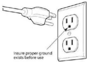
This appliance is equipped with a three-prong grounding plug for your protection against shock hazard and should be plugged directly into a properly grounded socket. Do not cut or remove the grounding prong from the plug.
- The gas range must be installed with all electrical connections in accordance with state and local codes. A standard electrical supply (115 V AC only, 60 Hz), properly grounded in accordance with the National Electrical Code and local codes and ordinances is required.
Do not under any circumstances cut or remove the third (ground) prong from the power plug. Electrical installation should comply with national and local codes.
REPLACEMENT PARTS
Only authorized replacement parts may be used in performing service on the range. Replacement parts are available from factory authorized parts distributors. Contact the nearest AVANTI parts distributor in your area.

CARBON MONOXIDE WARNING:
Carbon Monoxide is a possible danger when using any gas powered appliance.
All gas appliances MUST be installed by a licensed professional who is familiar with the Carbon Monoxide levels appropriate for each appliance.
The American Gas Association publishes CO emissions for appliances and heating equipment through the ANSI Std. Z21.1
The EPA reports that a maximum CO (Carbon Monoxide) level of 9 PPM over a 24 hour period is the residential interior ambient level standard.
(A properly ventilated home will have a normal CO level of less than 5 PPM.)
NON-VENTED GAS COOKING APPLIANCES:
In a residential application are normally used for a short period of time. The CO generated during the operation will disperse to the air in the home and be purged to the outside through the normal air exchange.
HOW TO USE THE TOP BURNERS
Control Knobs.
Each of the control knobs for the range is equipped with a ring of dual color LED status indicator lights
BLUE: When the knobs are in the OFF position the indicator lights will be in a bright blue color.
RED: When the knobs are in turned to an ON position the indicator lights will be in a bright red to indicate which burner is in use, the oven / broiler has been turned on or the function selector knob has been turned to activate the rotisserie or to turn on the oven light.
GAS BURNERS
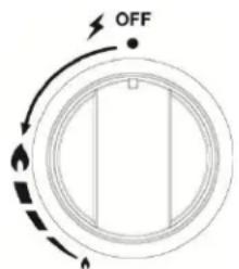
Gas flow to the burners is adjusted by turning the knobs which control the valves. Turning the knob so that the indicator line points to the symbols printed on the panel achieves the following functions:
When knob is rotated to the maximum position it will permit the rapid boiling of liquids, whereas the minimum position allows the simmer warming of food or maintaining boiling conditions of liquids.
ATTENTION: FOR YOUR SAFETY:
THIS UNIT HAS BEEN DESIGNED WITH A FLAME SENSOR SYSTEM THAT MONITORS THE COOKTOP BURNERS.
When using the cooktop, press the knob all the way in, turn to ignite the flame and hold for approximately 10 seconds to allow the system to heat to the appropriate temperature and allow the flow of gas to the selected burner.
To reduce the gas flow to minimum, rotate the knob further counter-clockwise to point the MIN position. Other intermediate operating adjustments can be
achieved by positioning the indicator between the MAX
and MIN positions, and never between the MAX and OFF positions.
When the range is not being used, set the gas knobs to their OFF positions and also close the gas shut-off valve placed on the main gas supply line.
In order to light the burner, you must:
1 – Push the knob all the way in, turn the knob in a counterclockwise direction up to the MAX position (maximum rate) to ignite, and hold the knob until the flame has been lit and allow the system to heat to the appropriate temperature and allow the flow of gas (approximately 10 seconds).
The sparks produced by the internal igniter will light the designated burner.
In the event that the local gas supply conditions make it difficult to light the burner in the MAX position, try again with the knob in MIN position.
2 - Adjust the gas valve to the desired position.
To re-light the burner, return the knob to the OFF position and repeat the operations for lighting.
Caution! The range becomes very hot during operation. Keep children well out of reach.
CHOICE OF BURNER
| DIAMETERS OF PANS WHICH MAY BE USED ON THE TOP BURNERS | ||
| BURNER | MINIMUM | MAXIMUM |
| Auxiliary | 4" 23/32 (12 cm) | 5" 1/2 (14 cm) |
| Semirapid | 6" 19/64 (16 cm) | 9" 7/16 (24 cm) |
| Rapid | 9" 7/16 (24 cm) | 10" 15/64 (26 cm) |
| Do not use pans with concave or convex bases | ||

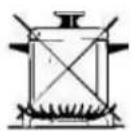
The symbols printed on the panel above the gas knobs indicate the correspondence between the knob and the burner.
The most suitable burner is to be chosen according to the diameter and volume capacity of the container to be warmed.
It is important that the diameter of the pots or pans suitably match the heating potential of the burners in order not to jeopardize the efficiency of the burners, bringing about a waste of gas fuel.
A small diameter pot or pan placed on a large burner does not necessarily mean that boiling conditions are reached quicker.

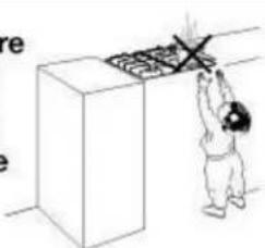
Make sure that the handles of cookware do not stick out over the edge of the range, to avoid them being knocked over by accident. This also makes it more difficult for children to reach the cooking vessels.
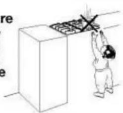
natural_image
Illustration of a person reaching toward a grid on a wall, with no visible text or symbolsHigh – Altitude effects on burners:
The surface burners used on this unit range from 2,500 BTU to 8,000 BTU on natural gas installation under 2,000 feet above sea level. Burner strength is derated by 4% per 1000 feet.
The gas oven is provided with two burners:
Oven burner, mounted on the lower part of the oven:
Broil burner, mounted on the upper part of the oven:
> USING THE OVEN FOR THE FIRST TIME
It is advised to follow these instructions
— Insert shelves and broiler grid and tray
- Turn the oven on to the maximum temperature position (500F) to eliminate possible traces of grease from the oven burner. The same operation should be followed for the broiler burner (knob on position BROIL)
- Unplug the power cord, let the oven cool down, then clean the interior of the oven with cloth soaked in water and detergent (neutral) then dry carefully.
OVEN BURNER
Carries out normal "oven cooking".
The gas flow to the burner is regulated by a thermostat which allows to maintain the desired oven temperature.
The control of the temperature is assured by a thermostatic probe positioned inside the oven.
The probe must be always kept in its housing, in a clean condition, as an incorrect position or a dirty probe may cause an alteration in the control of the temperature.
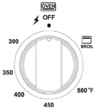
| GAS OVEN SETTING | |
| Number printed on the knob Temperature in °F | Corresponding temperature in °C |
| 300 | 149 |
| 350 | 177 |
| 400 | 204 |
| 450 | 232 |
| 500 | 260 |
OVEN THERMOSTAT
The numbers printed on the control panel indicate the increasing oven temperature value ( ^ F). To regulate the temperature, set the chosen number onto the control knob indicator.
The position BROIL serves only to turn on the broil burner.
NOTE: When the range will not be used for long periods of time, set the gas knobs to their OFF positions and also close the gas shut-off valve placed on the main gas supply line.
VERY IMPORTANT: The oven/broil shall be used always with the door closed.

WARNING!!
WARNING-VERY IMPORTANT NOTICE
Never obstruct the oven vent slots on the backsplash.
- Do not broil without using the broiling pan.
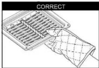
- Important: Use always suitable protective gloves when inserting / removing the broiling pan, shelves, pans on other cooking utensils from the oven.
- Attention: the range becomes very hot during operation
• Attention: the oven door becomes very hot during operation - Keep Children away
• Warning: The door is hot, make sure to use the handle
IGNITION OF THE OVEN BURNER
The thermostat allows the automatic control of the temperature.
The gas delivery to the oven burner is controlled by a two way thermostatic tap (oven and broil burners) with flame-failure device.
To light the oven burner operate as follows:
1) Open the oven door to its full extent.
WARNING: Risk of explosion! The oven door must be open during this operation.
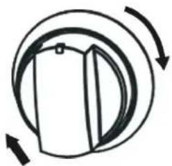
2) Lightly press and turn the thermostat knob counter-clockwise to max position or 500°F
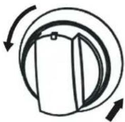
natural_image
Simple line drawing of a bag with arrows indicating rotation or motion (no text or symbols)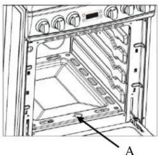
natural_image
Technical line drawing of an open industrial machine with labeled component A (no text or symbols beyond label)3) Press the knob inward and hold to activate the electronic ignition. Note that you will hear a "clicking" noise. Hold the knob pressed inward until the oven burner is lit. Once the oven burner is lit, release the knob.
In case of power outage, you can manually light the burner by pressing the knob inward and immediately approach a lighted match to the opening "A" (see the diagram above).
Never continue this operation for more than 15 seconds. If the burner has still not ignited, wait for about 1 minute prior to repeating the ignition.
4) When using the range for the first time or after long period of non-usage, keep pressing the knob inward for approximately 10 – 15 seconds after the burner has lit to ensure the gas valve has been accurately primed.
5) Close the oven door slowly and adjust the burner accordingly to the desired temperature. If the flame extinguishes for any reason, the safety valve will automatically shut off the gas supply to the burner.
To re-light the burner, first turn the oven control knob to the OFF position, wait for at least 1 minute and then repeat the lighting procedure.
Attention: the oven door becomes very hot during operation. Keep children away.
OVEN COOKING
Before introducing the food, preheat the oven to the desired temperature
For a correct preheating operation, it is advisable to remove the tray from the oven and introduce it together with the food, when the oven has reached the desired temperature.
Check the cooking time and turn off the oven 5 minutes before the theoretical time to recuperate the stored heat.
IGNITION OF THE BROIL BURNER
The broil burner generates the infra-red rays for broiling. To light the broil burner operate as follow: To light the oven burner operate as follows:
1) Open the oven door to its full extent.
WARNING: Risk of explosion! The oven door must be open during this operation.
2) Lightly press and turn the thermostat knob clockwise to the broil position.
natural_image
Simple line drawing of a circular object with internal curved arrows indicating rotation or movement (no text or symbols)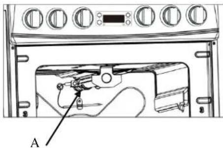
3) Press the knob inward and hold to activate the electronic ignition. Note that you will hear a "clicking" noise. Hold the knob pressed inward until the oven burner is lit. Once the oven burner is lit, release the knob.
In case of power outage, you can manually light the burner by pressing the knob inward and immediately approach a lighted match to the area "A" (see the diagram above).
Never continue this operation for more than 15 seconds. If the burner has still not ignited, wait for about 1 minute prior to repeating the ignition.
4) When using the range for the first time or after long period of non-usage, keep pressing the knob inward for approximately 10 – 15 seconds after the burner has lit to ensure the gas valve has been accurately primed.
5) Slowly close the oven door. If the flame extinguishes for any reason, the safety valve will automatically shut off the gas supply to the burner.
To re-light the burner, first turn the oven control knob to the OFF position, wait for at least 1 minute and then repeat the lighting procedure.
Always broil with oven door closed. Attention: the oven door becomes very hot during operation. Keep children away.
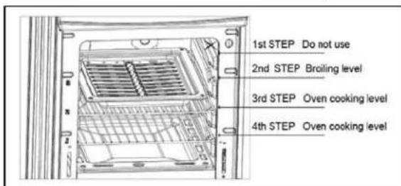
BROILING
Very important: the broil burner must always be used with the oven door closed.
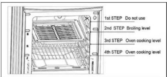
Position the oven rack on the second level from the top
-Turn on the broil burner, as explained in the preceding paragraphs and let the broil burner preheat for about 5 minutes with the door closed.
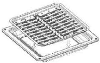
-Place the food to be cooked above the broiling pan.
-Introduce the broiling pan in the oven. The broiling pan should be placed above the shelf and it should be centered with the broil burner.
natural_image
Technical line drawing of a square ventilation grille with mounting holes (no text or symbols)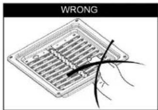
ROTISSERIE (MODEL DGR24P3S - ONLY)
This range is equipped with an automatic rotisserie for roasting.
The rotisserie feature allows for an even cooking and all-over browning of the meat while preventing the meat from cooking in its rendered grease. The rotisserie will turn the meat allowing it to baste itself while roasting.
Be sure that you have received the rotisserie accessories included with your unit.
(1) Rotisserie Spit – Rod
(2) Rotisserie Forks
Always use the included broiling pan when using the rotisserie to catch the rendered grease and allow for easy access to the meat when putting in and removing the rotisserie spit – rod.
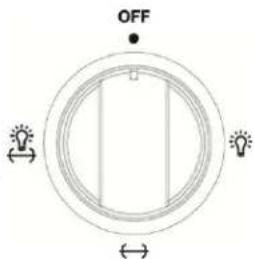
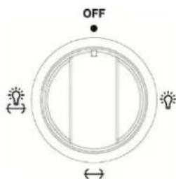
Your range offers two settings for the rotisserie function, rotisserie with the oven light on and with the light off.
To use the rotisserie, preheat the oven to the desired temperature.
Secure the meat to be cooked onto spit-rod using the rotisserie forks.
Insert the rotisserie spit-rod into the rotating assembly and select the desired rotisserie function (light on or light off).
Be sure the baking / broiling tray is below the meat being cooked to avoid spills and to prevent possible flare-up of the oven flame.
ALWAYS TURN THE ROTISSERIE FUNCTION TO OFF BEFORE REMOVING THE ITEMS FROM THE OVEN.
CAUTION - USE HEAT RESISTANT GLOVES WHEN REMOVING THE ITEMS FROM THE OVEN.
OVEN LIGHT
The range is equipped with a light that illuminates the oven to enable visually controlling the food that is cooking.
This light is controlled by a knob on the control panel. Simply turn the knob to the position marked with the light bulb on the right to turn on the oven light.
Model DG24P3S ONLY - the knob also has two additional positions marked with a bulb and a rotisserie icon as well as a rotisserie icon without light; this is to give you the option of having the light on or off during cooking with the rotisserie.
CARE & MAINTENANCE
GENERAL RECOMMENDATION
WARNING

Electrical Shock Hazard
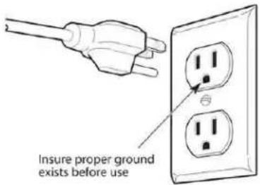
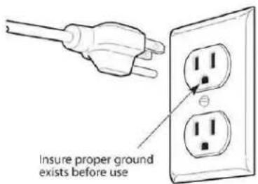
Plug into a grounded 3-prong outlet.
Do not remove ground prong.
Do not use an adapter.
Failure to follow these instructions can result in death, fire, or electrical shock.
Important: Before any operation of cleaning and maintenance disconnect the appliance from the electrical supply.
It is advisable to clean when the appliance is cold and especially for cleaning the enameled parts. Avoid leaving alkaline or acidic substances (lemon juice, vinegar, etc.) on the surfaces.
Avoid using cleaning products with a chlorine or acidic base.
The oven must always be cleaned after every use, using suitable products and keeping in mind that its operation for 30 minutes on the highest temperature eliminates most grime reducing it to ashes.
ENAMELED PARTS
All the enameled parts must be cleaned with a sponge and soapy water only or other non-abrasive products.
Dry preferably with a chamois leather.
If acid substances such as lemon juice, tomato conserve, vinegar etc. are left on the enamel for a long time they will etch it, making it opaque.
STAINLESS STEEL ELEMENTS
Stainless steel parts must be rinsed with water and dried with a soft and clean cloth or with a chamois leather.
For difficult dirt, use a specific non-abrasive product available commercially or a little hot vinegar.
Note: regular use could cause discoloring around the burners, because of the high flame temperature.
INSIDE OF OVEN
This must be cleaned regularly. With the oven warm, wipe the inside walls with a cloth soaked in very hot soapy water or another suitable product.
GAS VALVES
In the event of operating faults in the gas valves, shut the main gas supply and call the Service Department.
WARNING VERY IMPORTANT
Before any operation of maintenance disconnect the appliance from the electrical mains supply.
Do not use steam jet cleaners because the humidity could infiltrate into the appliance making it dangerous.
BURNERS AND CAST-IRON GRIDS
√ These parts can be removed and cleaned with appropriate products.
√ After cleaning, the burners and their flame distributors must be well dried and correctly replaced.
√ It is very important to check that the burner flame distributor and the cap has been correctly positioned - failure to do so can cause serious problems.
√ In appliances with electric ignition keep the electrode clean so that the sparks always strike.
√ Note: To avoid damage to the electric ignition do not use it when the burners are not in place.
CORRECT REPLACEMENT OF THE BURNERS
It is very important to check that the burner flame spreader "F" and the cap "C" have been correctly positioned. Failure to do so can cause serious problems.
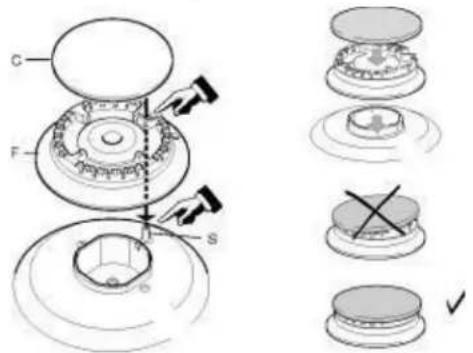
In appliances with electric ignition, check that the electrode "S" is always clean to ensure trouble-free sparking.
The ignition plug must be cleaned very carefully.
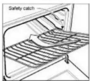
OVEN RACK INSTALLATION AND REMOVAL
The oven racks are provided with a safety catch to prevent accidental extraction.
They must be inserted as shown.
To pull them out remove the rack in the reverse order.
Figura 22
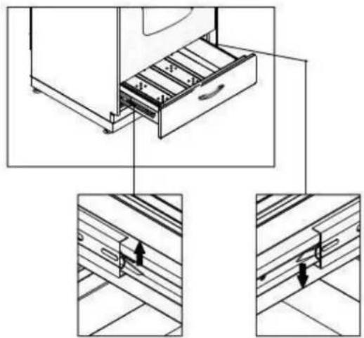
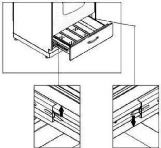
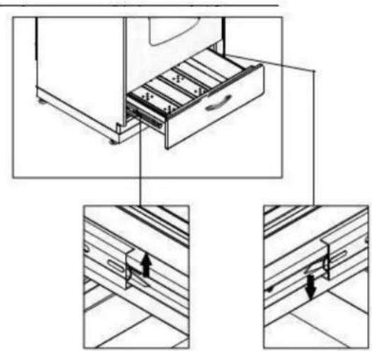
REMOVABLE STORAGE DRAWER
natural_image
Technical line drawing showing a file drawer with two views of the drawer (no text or symbols present)① Lift the left small hook upward, at the same time, push the right small hook downward.(see the picture)
②Pull the drawer out.
③To replace the drawer, align the drawer with the rails and push inward.
Do not store flammable material in the oven or in the bottom drawer.
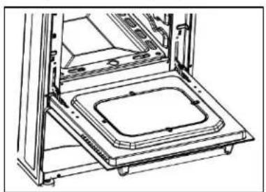
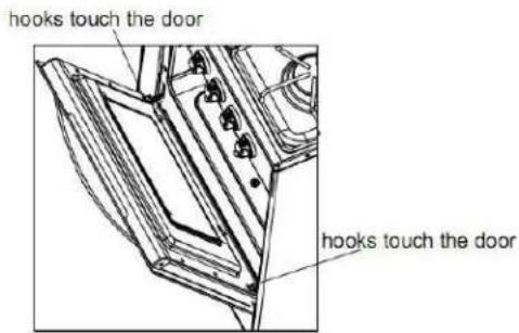
REMOVING THE OVEN DOOR
To facilitate oven cleaning, it is possible to remove the door. Please follow the instructions carefully:
REMOVING THE OVEN DOOR
- The oven door can easily be removed as follows:
- Open the door to the full extends.
— Lift the left and right hooks on the hinge.
— Hold the door as shown in the figure. - Gently close the door and lift the door with two hands when the hooks touch the door.
- Set the door on a soft flat surface.
- To replace the door, repeat the above steps in reverse order.
natural_image
Technical line drawing of a mechanical assembly with a rectangular component on top (no text or symbols)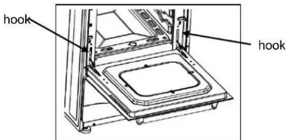
REPLACING THE OVEN LIGHT
- Let the oven cavity and broil burner cool down.
- Switch off the electric supply.
- Remove the protective cover.
- Unscrew and replace the bulb with a new one suitable for high temperature (200°\~500°F) having the same specifications: 120V 60Hz, 15W, E14.
- Replace the protective cover.
NOTE: Oven bulb replacement is not covered by your guarantee.
LEVELING THE RANGE
The range must be level to obtain proper operating. The four screws type leveling legs located on the corners at the bottom of range should be adjusted by turning them clockwise to make the range higher or counter-clockwise to lower the range until the range is level. Use a level on surface units to check the leveling of the range.
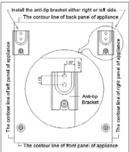
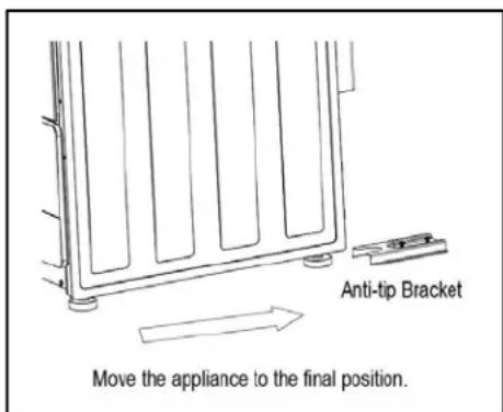
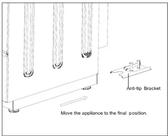
ANTI-TIP BRACKET INSALLATION
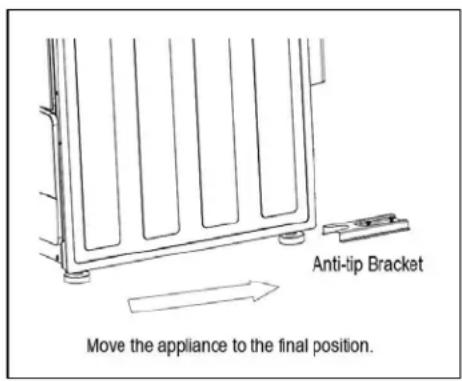
To reduce the risk of tipping the range by abnormal usage or improper door loading, the range must be secured by properly installing the anti-tip device packed with the appliance.
- Place the anti-tip bracket on the floor as shown figure. Anti-tip bracket can be installed on either right or left side.
• Make the locations of 2 holes of ant-tip bracket on the floor. - Use a 5/16" masonry drill bit and insert plastic anchor.
- Secure bracket to floor using screws supplied.
- Slide appliance into position.
NOTE: If range is relocated, the bracket must be removed and installed in new location.
PROBLEMS WITH YOUR GAS RANGE?
You can solve many common appliance problems easily, saving you the cost of a possible service call. Try the suggestions below to see if you can solve the problem before calling the servicer.
TROUBLESHOOTING GUIDE
| FIND YOUR PROBLEM HERE | POSSIBLE CAUSE | HOW TO FIX IT |
| Surface burners do not light. | Surface control has not been completely turned to the ON position. | Push knob all the way in and turn control to the HIGH position until burner ignites, continue to hold the knob in for approximately 10 seconds to allow the safety system to heat to the appropriate temperature and allow the flow of gas, then turn control to desired flame setting. |
| Burner ports are clogged. | Use a small gauge wire or needle to open ports. | |
| Burners not positioned properly. | Verify that the burners are positioned properly on the orifice hoods and the burners are sitting flat on the burner support with tabs engaged in slots. | |
| Range not set for appropriate gas input. | See range conversion section of installation manual. | |
| Pilot lights won't light due to power failure. | Light pilots manually. | |
| Range power cord is disconnected from the outlet. | Be sure power cord is plugged into grounded outlet. | |
| Flame burns halfway round. | Burner ports are clogged. | Use a small gauge wire or needle to open ports. |
| Moisture is present after cleaning. | Lightly fan the flame and allow burner to operate until flame is full. OR dry burners thoroughly following instructions in range “Cleaning” section. | |
| Range is not set for appropriate gas input. | See range conversion section of installation manual. | |
| Flame is orange. | Dust particles in main line. | Allow burner to operate for a few minutes until flame turns blue. |
| Range is not set for appropriate gas input. | See range conversion section of installation manual. | |
| Oven light does not work. | Burned out or loose bulb Tighten or replace oven light bulb. | |
| Oven or broiler does not heat. | Range is not set for appropriate gas input. | See range conversion section of installation manual. |
| Temperature control not set properly. | Make sure temperature control is set at desired temperature. | |
| Pilot light will not light due to power failure. | Light pilots manually. | |
| House fuse has blown or circuit breaker has tripped. | Check/reset circuit breaker and/or replace fuse. Do not increase fuse capacity. If the problem is a circuit overload, have it corrected by a qualified electrician. | |
| Range cord is disconnected from outlet. | Be sure the power cord is plugged into a grounded outlet. | |
| Oven temperature is inaccurate. | Oven capillary bulb not positioned properly. | Verify that capillary bulb is snapped in clips straight and not touching sides or coated with oven cleaner or food. |
| Temperature control not set properly. | Make sure the temperature control knob is set at the desired temperature. | |
| Improper use of foil. | Keep foil clear of holes in oven bottom and off of oven sides. | |
| Vent blocked. Keep vent on backguard clear. | ||
| Range not set for appropriate gas input. | See range conversion section of installation manual. | |
| Smoke or odor on initial oven operation. | This is normal. | |
| Range is not level. | Poor installation. | Place oven rack in center of oven. Place a level on the rack. Adjust leveling legs. |
| Weak or unstable floor. | Be sure floor is level and can adequately support range. Contact carpenter to correct sagging or sloping floor. | |
| Kitchen cabinet misalignment may make range appear to be unleveled. | Be sure cabinets are square and have sufficient room for range clearance. Contact cabinet maker to correct problem | |
| Oven smokes excessively. | Meat too close to broiler burner. | Reposition the broiler pan to provide more clearance between the meat and the broiler burner |
| Meat not prepared properly. | Remove excess fat from meat. | |
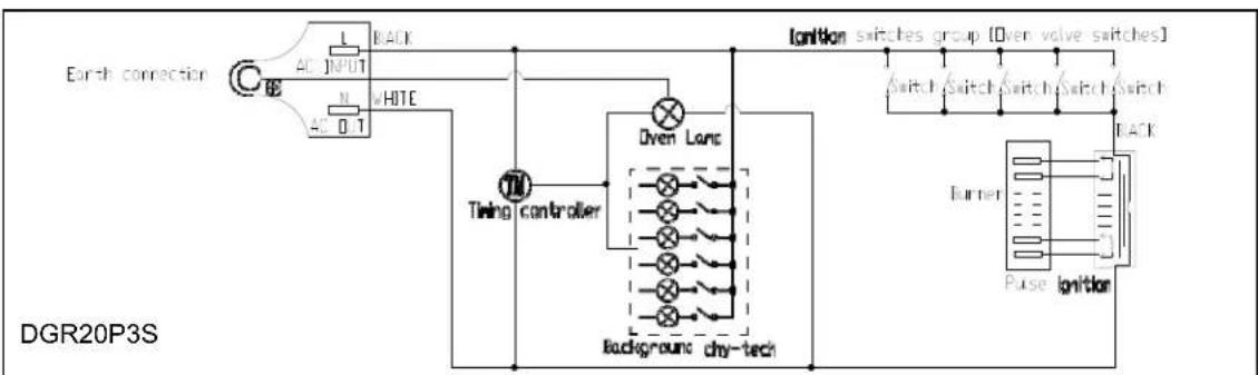
Wiring Diagram
flowchart
graph TD
    A["Earth connection"] --> B["AC INPUT"]
    B --> C["AC 0.1"]
    C --> D["BACK"]
    D --> E["White"]
    E --> F["Timing controller"]
    F --> G["Dven Lamp"]
    G --> H["Background dry-tech"]
    H --> I["Ionition switches group [Oven valve switches"]]
    I --> J["Switch"]
    I --> K["Switch"]
    I --> L["Switch"]
    I --> M["Rack"]
    M --> N["Pulse ignition"]
    N --> O["Turner"]
    O --> P["Ground"]
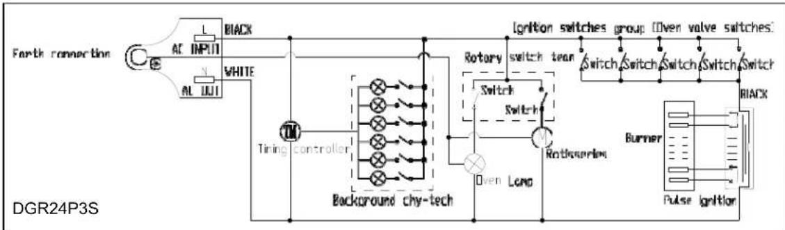
flowchart
graph TD
    A["Earth connection"] --> B["AC INPUT"]
    A --> C["AL IOUT"]
    B --> D["WHITE"]
    C --> D
    D --> E["Tiring controller"]
    E --> F["Background chy-tech"]
    F --> G["Rotary switch team"]
    G --> H["Ignition switches group (Oven valve switches)"]
    H --> I["Switch"]
    H --> J["Switch"]
    H --> K["Switch"]
    H --> L["Switch"]
    H --> M["Switch"]
    H --> N["Switch"]
    H --> O["Switch"]
    H --> P["Switch"]
    H --> Q["Switch"]
    H --> R["Switch"]
    H --> S["Switch"]
    H --> T["Switch"]
    H --> U["Rotikensor"]
    U --> V["Burner"]
    V --> W["Pulse ignition"]
    W --> X["Black"]
SERVICE FOR YOUR GAS RANGE
We are proud of our customer service organization and the network of professional service technicians that provide service on your Avanti appliances. With the purchase of your Avanti appliance, you can have the confidence that if you ever need additional information or assistance, the Avanti Products Customer Service team will be here for you. Just call us toll-free.
AVANTI PRODUCTS CUSTOMER SERVICES
| Product Information800-323-5029 | Whatever your questions are about our products, help is available. |
| Part Orders800-220-5570 | You may order parts and accessories that will be delivered directly to your home by personal check, money order, Master Card, or Visa. |
| In-Home Repair Service800-220-5570 | An Avanti Products authorized service center will provide expert repair service, scheduled at a time that is convenient for you. Our trained servicers know your appliance inside and out. |
| YOUR AVANTI PRODUCTSWARRANTY | Staple your sales receipt here. Proof of original purchase date is needed to obtain service under warranty. |
| WHAT IS COVERED - LIMITED ONE-YEAR WARRANTYAvanti Products warrants that the product is free from defects in materials and/or workmanship for a period of twelve (12) months from the date of purchase by the original owner. The foregoing timeline begins to run upon the date of purchase, and shall not be stalled, tolled, extended, or suspended for any reason whatsoever unless described in detail in the warranty document. For one year from the date of purchase by the original owner, Avanti products will, at its option, repair or replace any part of the product which proves to be defective in material or workmanship under normal use. Avanti Products will provide you with a reasonably similar product that is either new or factory refurbished. During this period Avanti Products will provide all parts and labor necessary to correct such defects free of charge, so long as the product has been installed and operated in accordance with the written instructions in this manual. In rental or commercial use, the warranty period is 90 days. All Avanti appliances of 3.5 cubic feet capacity or less must be brought/sent to the appliance service center for repair. | |
| FULL 30 - DAY WARRANTYFrom the date of purchase on glass parts and finish of porcelain enamel, painted, or bright metal finished parts. | |
| WARRANTY EXCLUSIONS / WHAT IS NOT COVERED:The warranty coverage described herein excludes all defects or damage that are not the direct fault of Avanti Products, including without limitation, one or more of the following: | |
| A failure to comply with any applicable state, local, city, or county electrical, plumbing and/or building codes, regulations, or laws, including failure to install the product in strict conformity with local fire and building codes and regulations.Any external, elemental and/or environmental forces and factors, including without limitation, rain, wind, sand, floods, fires, mud slides, freezing temperatures, excessive moisture or extended exposure to humidity, lightning, power surges, structural failures surrounding the appliance, and acts of God. | |
| Content losses of food or other content due to spoilage.Incidental or consequential damagesParts and labor costs for the following will not be considered as warranty:Evaporator doors, door springs, and/or frames.Inner door panels, door shelves, door rails, and/or door supports.Chest freezer lid liners.Vegetable crispers.Light bulbs and/or plastic housing.Plastic cabinet liners.Punctured evaporator that voids the warranty on the complete sealed system. | Shipping and handling costs associated with the replacement of the unit.Repairs performed by unauthorized servicers.Service calls that are related to external problems, such as abuse, misuse, inadequate electrical power, accidents, fire, floods, or any other acts of God.Failure of the product if it is used for other than it intended purpose.The warranty does not apply outside the Continental USA.Surcharges including but not limited to, any after hour, weekend, or holiday service calls, tolls, ferry trip charges, or mileage expense for service calls to remote areas. |
| In no event shall Avanti Products have any liability or responsibility whatsoever for damage to surrounding property, including cabinetry, floors, ceilings, and other structures and/or objects around the product. Also excluded from this warranty are scratches, nicks, minor dents, and other cosmetic damages on external surfaces and exposed parts; Products on which the serial numbers have been altered, defaced or removed; service visits for customer education, or visits where there is nothing wrong with the product; correction of installation problems (you are solely responsible for any structure and setting for the product, including all electrical, plumbing and/or other connecting facilities, for proper foundation/flooring, and for any alterations including without limitation cabinetry, walls, floors, shelving etc., as well as the resetting of breakers or fuses. | |
| OUT OF WARRANTY PRODUCTAvanti Products is under no obligation, at law or otherwise, to provide you with any concessions, including repairs, pro-rates, or product replacement, once this warranty has expired.WARRANTY - RANGES / TOASTER Ovens | |
natural_image
Pure electrical circuit lines without any symbolsMODELO # DGR20P3S
MODELO # DGR24P3S
COCINA
Model #: DGR24P3S
Digital Display
Up (+) Button
Down (-) Button
Set Button
Back Light ON/OFF Button
natural_image
Cartoon illustration of a child reaching for a large oven with a fire extinguisher (no text or symbols)natural_image
Simple line drawing of a door with curved arrows indicating rotation or motion (no text or symbols)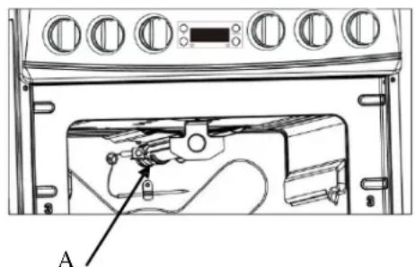
natural_image
Technical line drawing of a refrigerator interior with labeled component A (no text or symbols beyond label)Electrical Shock Hazard
Plug into a grounded 3-prong outlet.
Do not remove ground prong.
Do not use an adapter.
Failure to follow these instructions can result in death, fire, or electrical shock.
Before any operation of maintenance disconnect the appliance from the electrical mains supply.
GAVETA DE ALMACENAJE REMOVIBLE
natural_image
Technical diagram showing a file drawer with two views of the drawer, no text or symbols present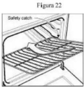
WARNING: IF THE INFORMATION IN THIS MANUAL IS NOT FOLLOWED EXACTLY, A FIRE OR EXPLOSION MAY RESULT CAUSING PROPERTY DAMAGE, PERSONAL INJURY, OR DEATH.
√ Do not store or use gasoline or other flammable vapors and liquids in the vicinity of this or any other appliance.
√ WHAT TO DO IF YOU SMELL GAS:
- Do not try to light any appliance.
- Do not touch any electrical switch; do not use any phone in your building.
- Immediately call your gas supplier from a neighbor's phone. Follow the gas supplier's instructions.
- If you cannot reach your gas supplier, call the fire department.
√ Installation and service must be performed by a qualified installer, service agency, or the gas supplier.
AIDEZ-NOUS VOUS AIDER ...
Model: DGR24P3S
natural_image
Pure diagram of a multi-stage device layout with circular components and control knobs, no text or symbols present.MODELÉ # DGR20P3S
natural_image
Pure electrical circuit lines without any symbolsMODELÉ # DGR24P3S
CUISSON
| BTU / h Notes | |||
| 20" 24" | |||
| 1 | Auxiliaire 2500 | 2500 | |
| 2 | Droit Semi-rapide | 4300 | 4300 |
| 3 | Gauche semi-rapide | 4300 | 4300 |
| 4 | Rapide 8000 | 8000 | |
Note:
Make sure that the handles of cookware do not stick out over the edge of the range, to avoid them being knocked over by accident. This also makes it more difficult for children to reach the cooking vessels.
natural_image
Simple line drawing of a bag with arrows indicating rotation or motion (no text or symbols)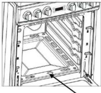
natural_image
Technical line drawing of an open oven or rack cabinet with ventilation grilles and mounting brackets (no text or symbols)natural_image
Simple line drawing of a mechanical component with curved arrows indicating motion (no text or symbols)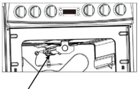
natural_image
Line drawing of a refrigerator interior with doors, wheels, and a handle (no text or symbols)Electrical Shock Hazard
Plug into a grounded 3-prong outlet.
Do not remove ground prong.
Do not use an adapter.
Failure to follow these instructions can result in death, fire, or electrical shock.
Before any operation of maintenance disconnect the appliance from the electrical mains supply.
natural_image
Technical diagram showing a drawer with internal compartments and two views of the drawer's internal structure (no text or symbols present)Tiroir de rangement AMOVIBLE
natural_image
Technical line drawing of a mechanical assembly with no visible text or symbols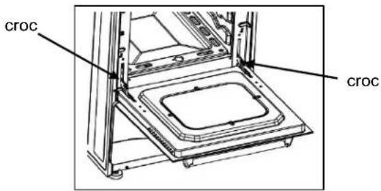
PROBLÈMES AVEC VOTRE GAZ?
flowchart
graph TD
    A["Ground connection"] --> B["AC INPUT"]
    A --> C["AC OUT"]
    B --> D["Black"]
    C --> E["White"]
    D --> F["Timing controller"]
    E --> F
    F --> G["Background chy-tech"]
    G --> H["Over Lamp"]
    H --> I["Rotary switch team"]
    I --> J["Ignition switches group"]
    J --> K["Switch"]
    J --> L["Switch"]
    J --> M["Switch"]
    J --> N["Switch"]
    J --> O["Switch"]
    J --> P["Rearner"]
    P --> Q["Pulse ignition"]
    Q --> R["Black"]
    G --> S["Rotisseries"]
SERVICE POUR VOTRE GAZ
AVANTI PRODUCTS NE SERA PAS RESPONSABLE DES DOMMAGES ACCESSOIRES OU INDIRECTS.
Thank you for purchasing this fine Avanti product. Please fill out this form and return it to the following address within 100 days from the date of purchase and receive these important benefits:
Avanti Products, LLC.
P.O.Box 520604 - Miami, Florida 33152
Protect your product:
We will keep the model number and date of purchase of your new Avanti product on file to help you refer to this information in the event of an insurance claim such as fire or theft.
➢ Promote better products:
We value your input. Your responses will help us develop products designed to best meet your future needs.
----------(detach here)
Avanti Registration Card
| Name | Model # Serial # | ||
| Address | Date Purchased Store / Dealer Name | ||
| City | State | Zip | E-mail Address |
| Area Code Phone Number | Occupation | ||
| Did You Purchase An Additional Warranty | As your Primary Residence, Do You: | ||
| ☐ Extended☐ None | ☐ Own ☐ Rent | ||
| Reason for Choosing This Avanti Product: Please indicate the most important factors That influenced your decision to purchase this product: | Your Age:☐ under 18 ☐ 18-25 ☐ 26-30☐ 31-35 ☐ 36-50 ☐ over 50Marital Status:☐ Married ☐ Single | ||
| ☐ Price☐ Product Features☐ Avanti Reputation☐ Product Quality☐ Salesperson Recommendation☐ Other: ____☐ Friend / Relative Recommendation☐ Warranty☐ Other: ____ | Is This Product Used In The:☐ Home ☐ BusinessHow Did You Learn About This Product:☐ Advertising☐ In-Store Demo☐ Personal Demo | ||
Comments:
DGR20P3S / DGR24P3S - 02062018
PRINTED IN CHINA

- INSTRUCTION MANUAL MANUAL DE INSTRUCCIONES MANUEL D'INSTRUCTIONS
- RANGE SAFETY
- CAUTION
- IN THE COMMONWEALTH OF MASSACHUSETTS
- BEFORE YOU BEGIN!
- BEFORE INSTALLATION
- Installation in Manufactured (Mobile) Homes:
- IMPORTANT SAFE GUIDES
- DANGER
- WARNING
- THE ANTI-TIP BRACKET
- HELP US HELP YOU...
- Read this guide carefully.
- Avanti Customer Service 800-220-5570
- Write down the model and serial numbers.
- IF YOU NEED SERVICE
- CAUTION:
- Digital Kitchen Timer
- Model #: DGR20P3S
- Model #: DGR24P3S
- CLOCK: (APPLIES TO BOTH MODELS)
- COOK TIMER: (APPLIES TO BOTH MODELS).
- OVEN LIGHT: (Model DGR20P3S - ONLY).
- BACKLIGHT: (Knob Indicator Lights - Model DGR20P3S).
- BACKLIGHT: (Knob Indicator Lights - Model DGR24P3S).
- Before Using Your Gas Range
- IMPORTANT PRECAUTIONS AND RECOMMENDATIONS
- It is advised to follow these instructions:
- ATTENTION:
- IMPORTANT PRECAUTIONS AND RECOMMENDATIONS FOR USE OF ELECTRICAL APPLIANCES
- GENERAL INFORMATION
- WARNING!!
- CAUTION: Range is heavy; use care in handling.
- \*\* WHAT TO DO IF YOU SMELL GAS \*\*
- Follow the gas supplier instructions.
- ELECTRICAL GROUNDING INSTRUCTIONS
- FOR PERSONAL SAFETY, THIS APPLIANCE MUST BE PROPERLY GROUNDED.
- REPLACEMENT PARTS
- CARBON MONOXIDE WARNING:
- HOW TO USE THE TOP BURNERS
- Control Knobs.
- GAS BURNERS
- ATTENTION: FOR YOUR SAFETY:
- CHOICE OF BURNER
- > USING THE OVEN FOR THE FIRST TIME
- OVEN BURNER
- OVEN THERMOSTAT
- WARNING-VERY IMPORTANT NOTICE
- IGNITION OF THE OVEN BURNER
- WARNING: Risk of explosion! The oven door must be open during this operation.
- OVEN COOKING
- IGNITION OF THE BROIL BURNER
- Never continue this operation for more than 15 seconds. If the burner has still not ignited, wait for about 1 minute prior to repeating the ignition.
- BROILING
- ROTISSERIE (MODEL DGR24P3S - ONLY)
- OVEN LIGHT
- CARE & MAINTENANCE
- GENERAL RECOMMENDATION
- Electrical Shock Hazard
- ENAMELED PARTS
- STAINLESS STEEL ELEMENTS
- INSIDE OF OVEN
- GAS VALVES
- WARNING VERY IMPORTANT
- BURNERS AND CAST-IRON GRIDS
- CORRECT REPLACEMENT OF THE BURNERS
- OVEN RACK INSTALLATION AND REMOVAL
- Do not store flammable material in the oven or in the bottom drawer.
- REMOVING THE OVEN DOOR
- REPLACING THE OVEN LIGHT
- LEVELING THE RANGE
- ANTI-TIP BRACKET INSALLATION
- PROBLEMS WITH YOUR GAS RANGE?
- SERVICE FOR YOUR GAS RANGE
- COCINA
- GAVETA DE ALMACENAJE REMOVIBLE
- WARNING: IF THE INFORMATION IN THIS MANUAL IS NOT FOLLOWED EXACTLY, A FIRE OR EXPLOSION MAY RESULT CAUSING PROPERTY DAMAGE, PERSONAL INJURY, OR DEATH.
- AIDEZ-NOUS VOUS AIDER ...
- Tiroir de rangement AMOVIBLE
- PROBLÈMES AVEC VOTRE GAZ?
- SERVICE POUR VOTRE GAZ
- AVANTI PRODUCTS NE SERA PAS RESPONSABLE DES DOMMAGES ACCESSOIRES OU INDIRECTS.
- Protect your product:
- ➢ Promote better products:
Brand : Avanti
Model : DGR24P3S
Category : Cooker