
MCUS4NEK3N - Air Conditioning SAMSUNG - Free user manual and instructions
Find the device manual for free MCUS4NEK3N SAMSUNG in PDF.
Download the instructions for your Air Conditioning in PDF format for free! Find your manual MCUS4NEK3N - SAMSUNG and take your electronic device back in hand. On this page are published all the documents necessary for the use of your device. MCUS4NEK3N by SAMSUNG.
USER MANUAL MCUS4NEK3N SAMSUNG
- Thank you for purchasing this Samsung air conditioner.
- Before operating this unit, please read this installation manual carefully and retain it for future reference. ki]_TW]`WZhTW\pttj|GrniluRmyUGGGX YWYYTXXTYYGGG㝘㤸G_a\_a\\2 Safety precautions ..........................................................................................................................................................................................................................3 Mesures de sécurité .......................................................................................................................................................................................................................5 Preparing the installation ............................................................................................................................................................................................................7 Space requirements ....................................................................................................................................................................................................................10 Refrigerant piping ........................................................................................................................................................................................................................17 Wiring ................................................................................................................................................................................................................................................20 MCU Installation Checklist .......................................................................................................................................................................................................31 Contents Correct Disposal of This Product (Waste Electrical & Electronic Equipment) (Applicable in countries with separate collection systems) This marking on the product, accessories or literature indicates that the product and its electronic accessories (e.g. charger, headset, USB cable) should not be disposed of with other household waste at the end of their working life. To prevent possible harm to the environment or human health from uncontrolled waste disposal, please separate these items from other types of waste and recycle them responsibly to promote the sustainable reuse of material resources. Household users should contact either the retailer where they purchased this product, or their local government oce, for details of where and how they can take these items for environmentally safe recycling. Business users should contact their supplier and check the terms and conditions of the purchase contract. This product and its electronic accessories should not be mixed with other commercial wastes for disposal. (For India only) For more information on safe disposal and recycling, visit our website www.samsung.com/in/support or contact our Helpline numbers - 1800 40 SAMSUNG (1800 40 7267864) 1800 5 SAMSUNG (1800 5 7267864). For correct disposal of this product, please visit http://www.samsung.com/weee.pdf Points de collecte sur www.quefairedemesdechets.fr REPRISEÀ LA LIVRAISONÀ DÉPOSEREN MAGASINÀ DÉPOSEREN DÉCHÈTERIEOU OU Cet appareil,ses accessoires,piles et cordonsse recyclent ki]_TW]`WZhTW\pttj|GrniluRmyUGGGY YWYYTXXTYYGGG㝘㤸G_a\_a\\3 The safety information and precautions below must be kept for the safety of users and installers. Before installing an air conditioner, please read this manual thoroughly to ensure that you know how to safely and eciently install a new appliance. J This product uses R-410A refrigerant. – When using R-410A, moisture or foreign substances may aect the capacity and reliability of the product. Safety precautions must be taken when installing the refrigerant pipe. – The designing pressure of the system is 4.1MPa. Select appropriate material and thickness according to the regulations. – R-410A is a quasi-azeotrope of two refrigerants. Make sure to charge with liquid phase when lling refrigerant. If you charge gaseous refrigerant, it may aect the capacity and reliability of the product as a result of change formation of the refrigerant. J Connect the indoor units for R-410A refrigerant. Check whether the indoor units can be connected with the product’s catalogue. (When incorrect indoor units are connected, they cannot operate normally.)
After installation and trial operation, explain to the customer how to use the air conditioner and give the installation manual to the user. J The manufacturer is not responsible for accidents due to incorrect installation. Any claims caused by failing to keep the safety precautions are installer’s responsibility. (The installer is responsible for the service cost.) J This appliance is not intended for use by persons (including children) with reduced physical, sensory or mental capabilities, or lack of experience and knowledge, unless they have been given supervision or instruction concerning use of the appliance by a person responsible for their safety. Children should be supervised to ensure that they do not play with the appliance. J If the supply cord is damaged, it must be replaced by the manufacturer, its service agent or similarly qualied persons in order to avoid a hazard. WARNING In case of not following the safety precautions, the service agent or the user may get the risk of serious wound or death. CAUTION In case of not following the safety precautions, the service agent or the user may get the risk of injury or loss of property. FOR INSTALLATION WARNING Installation must be done by the installer or its service agent. X Installation by an unqualified person may cause a water leakage, electric shock or fire and so on. Install the unit correctly according to the installation manual. X An incorrect installation may cause a water leakage, electric shock or fire. When installing the unit in a small place, take measures in order to keep the refrigerant concentration from exceeding allowable safety limits in the event of a refrigerant leak. X Excessive refrigerant concentration can lead to suffocation. If any gas or impurities except R-410A refrigerant get into the refrigerant pipe, serious problems may occur and this may cause injury. When installing the unit, only use the components and tools which are specied for the installation. X Using the uncertified components and tools may cause a unit fall, water leakage, electric shock, and a fire. (Never use the components and pipe for R-22 refrigerant)Install the unit safely on a place that can support its weight. X If the place cannot support its weight, the unit may fall down and cause injury. Check out the safety precautions below before installing or xing the unit. X Before welding the unit, you must remove all the hazardous materials around the unit that may cause an explosion and a fire. X When refrigerant is in the product or the pipe before welding the unit, you must remove the refrigerant. – If you weld the unit when there is refrigerant inside, the increased pressure of refrigerant may explode or break the leaking spot so that causes serious injuries. X When welding the unit, please use nitrogen gas to prevent oxide from generating in the pipe Make sure to cut o all the power supply before installing, xing, and cleaning the unit. When the electric wire is damaged, you must exchange it by the manufacturer or its service agent, or a person who has the equivalent qualication. When turning on the power, make sure to connect the power supply to the circuit breaker designated for indoor units. (ELCB, ELB, MCCB) X If you do not install the circuit breaker for MCU(ELCB, ELB, MCCB), excessive current or failure to blocking the power supply may cause electric shock, a fire. Safety precautions ki]_TW]`WZhTW\pttj|GrniluRmyUGGGZ YWYYTXXTYYGGG㝘㤸G_a\_a\]4 Safety precautions FOR INSTALLATION WARNING Make sure to connect wires thoroughly and x them rmly so that no outer pressure of the wires would put on the terminal block. X If the terminal is loose, it may generate heat and cause a fire. Supplied power should be more or less than 2% of the rated power. X If the power is supplied unevenly, a life span of the storage battery shortens. If the supplied power is more than 4 % of the rated power, the unit terminates and indicates errors to protect it.Make sure the interior power supply shouldn’t be over the maximum voltage or under the minimum voltage. X Otherwise, it could result in malfunction of the unit due to damaged electrical components or decreased function of components. Only use copper wire as the power cable and all wiring, components and materials should comply with the applicable local and national codes.Make sure that all wiring is properly installed. X Otherwise, the unit can be heated and cause a fire.Never use the pipe and are parts for R-22 refrigerant.In case of a refrigerant gas leakage during installation, please ventilate the area. X If refrigerant gas combines with inflammable materials, toxic gases can be generated. The electric work must be done by service agent or qualied persons according to national wiring regulations and use only rated cable. X Voltage drop, shortage of power supply, improper electric work and using unapproved wires can cause an electric shock or a fire. FOR INSTALLATION CAUTION Make sure to earth. X Do not connect the earth wire to the gas pipe, lighting rod or telephone wire. X If earthing is incomplete, electric shock or fire may occur. Make sure that the condensed water from the drain hose runs out properly based on this installation manual and insulate the drain pipe so that frost does not generate. X If the draining work is done incompletely, property damage may occur due to a leakage. Install the power cable and communication cable of MCU at least 1m away from the electric appliances and at least 2m away from the lightning rod. X However, you may hear a noise 1 meter away from the unit depending on the condition of the electric wave. Install MCU away from lighting apparatus using the ballast. X If you use the wireless remote control, it may not operate normally. Do not install the unit in following places. X The place packed with mineral oil and the place where there are lots of moisture, or arsenic acid: The resin parts may burn and cause the fall of the components or a refrigerant leakage. X The place where corrosive gas such as sulfurous acid gas generates from the vent pipe or air outlet: The copper pipe or connection pipe may corrode and refrigerant may leak. X The place where there is a machine that generates electromagnetic waves: The unit may not operate normally due to malfunction in the control system. X The place where there is a possibility of combustible gas leakage, and where inflammable materials like thinner or gasoline is handled. The place where a carbon fiber or inflammable dust is floating in the air: If the gas leaks and stays around the main valve, it may result in a fire. X The places where have a possibility of the MCU corrosion like a spa and a shore. When there is a possibility that the place in which MCU is installed could be the shelter of small animals, take proper measures to prevent this situation in advance. X If small animals contact the unit, this may result in malfunction of the unit or cause a fire and smoke. Please remind users of cleaning the place around MCU. J Any claims caused by failing to keep the safety precautions are installer’s responsibility. (The installer is responsible for the service cost.) ki]_TW]`WZhTW\pttj|GrniluRmyUGGG[ YWYYTXXTYYGGG㝘㤸G_a\_a\]5 Les renseignements sur la sécurité et les précautions ci-dessous doivent être conservés pour garantir la sécurité des utilisateurs et des installateurs. Avant d'installer un climatiseur, veuillez lire attentivement ce manuel pour vous assurer que vous savez comment installer ecacement et en toute sécurité un nouvel appareil. J Ce produit utilise du uide frigorigène R-410A. – Lors de l'utilisation de R-410A, l'humidité ou les substances étrangères risquent d'aecter les capacités et la abilité du produit. Des précautions de sécurité doivent être respectées lors de l'installation du conduit de uide frigorigène. – La pression de conception du système est de 4,1MPa. Sélectionnez les matériaux et les épaisseurs conformément aux réglementations en vigueur. – Le R-410A est un quasi-azéotrope de deux uides frigorigènes. Assurez-vous de charger le uide frigorigène en phase liquide. Si vous chargez un réfrigérant gazeux, cela risque d'aecter la capacité et la abilité du produit suite à un changement dans la formation du uide frigorigène.
J Soundproof and soundproong materials Name MXJ-YM1509M Shape Selecting the refrigerant pipe for installation The design pressure of MCU for R-410A is about 4.1 MPa (594.6psi). For safe use of the product, please refer to the table below in selecting the installation pipe. Outer diameter Minimum thickness Temper grade mm inch mm inch
- For pipes larger than Ø 19.05mm(3/4"), drawn type (C1220T-1/2H or C1220T-H) type copper pipe must be used. If an annealed type (C1220T-O) copper pipe is used, pipe may break due to its low pressure resistance and cause personal injury.
ø 22.22 (ø 7/8) ø 19.05 (ø 3/4) ø 9.52 (ø 3/8) ø 9.52 (ø 3/8) WELDING ø 15.88 (ø 5/8) WELDING Liquid pipe connected to indoor unit Gas pipe connected to indoor unit
Space requirements 1. Refrigerant noise can be generated during MCU operation. Do not install the unit in spaces that require silence, such as bedrooms, libraries, hospitals, oces etc.
2. Do not install the MCU in the ceiling of living spaces. Noise generated from the MCU may disrupt occupant comfort.
<Spaces with open ceiling> <Ceiling of the oce>
3. It is normally recommended to install MCU in a hallway but a bulkhead should be installed to minimize the noise from
being transferred to living area. (Refer to the below gure) <There is no risk of noise transfer> <There is a risk of noise transfer> MCU MCU Bulkhead Living area Living areaHallway HallwayLiving area Living area J Soundproof and soundproong materials X The place where MCU is installed and the interior walls should have a high soundproof ability. (Bricks, Concretes, Cement) X The ceiling where MCU is installed should be coated with quality textile that has a good soundproof function. X Minimize the size of the hole between the walls and the pipe connection. After the installation, block the gap to prevent noise from leaking.
4. Secure over 0.25m(0.82') of space when MCU is being xed to the concrete of the ceiling.
5. MCU may generate noise so don’t install it too close to the ceiling textile.
6. Each pipe hanger should be placed at 1.5m(4.92') interval to support its weight rmly.
If the pipe or the hanger isn’t xed rmly, the unit may fall and cause a property damage or loss of life. 7. When 'Low temperature cooling range expansion' option is set for constant cooling operation throughout the year, noise of the MCU may get louder during wintertime. Therefore, above installation requirements must be followed. Space requirements ki]_TW]`WZhTW\pttj|GrniluRmyUGGGXW YWYYTXXTYYGGG㝘㤸G_a\_a\]11
8. Select a place where the structure can support the weight of the MCU and indoor units that also have strong vibration
resistance without any slope. If the structure is not strong enough, MCU may fall down and cause injury. *Height (mm) MCU-S6*
MCU-S8* Ceiling textile Ceiling MCU 1.5m(5') or less 1.5m(5') or less Pipe hanger Refrigerant pipe Do not install the MCU to close to the ceiling textile[minimum 50mm(2")] 76mm (3") or more *Height
9. Select an installation location with enough space for service and repair.
Model MCU-S12NEK1N MCU-S8NEK1N MCU-S6NEK2N Exterior of MCU Number of connectable indoor units at one port Up to 8 units Up to 8 units Up to 8 units Maximum number of indoor units (Total)
The maximum capacity of the connectable indoor units at one port 16 kW (54MBH) 16 kW (54MBH) 16 kW (54MBH) The maximum capacity of the connectable indoor units at one port (with Y-JOINT)
(108 MBH) The maximum capacity of the connectable indoor units
(216MBH) Internal EEV Not included Cannot connect indoor unit without internal EEV Model MCU-S4NEK3N MCU-S2NEK2N MCU-S1NEK1N Exterior of MCU Number of connectable indoor units at one port Up to 8 units Up to 8 units Up to 8 units Maximum number of indoor units (Total)
The maximum capacity of the connectable indoor units at one port 16 kW (54MBH) 16 kW (54MBH) 16 kW (54MBH) The maximum capacity of the connectable indoor units at one port (with Y-JOINT)
The maximum capacity of the connectable indoor units
(108MBH) 16 kW (54MBH) Internal EEV Not included Cannot connect indoor unit without internal EEV CAUTION
- If the sum of the connected indoor unit capacity connected to the MCU is greater than 67.2kW (228 MBH), performance may vary depending on operating conditions.
- The incoming pipe diameters supplying refrigerant to the MCU are determined based on the sum of the connected indoor units. If these pipe diameters are dierent than the MCU pipe diameters, use the provided reducers to connect to the MCU. If the provided reducers are not the correct size, eld supplied reducers must be used.
Model MCU-S12NEK1N MCU-S8NEK1N MCU-S6NEK2N Example installing (Each port connection) MCU-S4NEK3N MCU-S2NEK2N MCU-S1NEK1N Example installing (MCU series connection) MCU MCU MCU series connection Installing indoor units Indoor units under 16.0 kW (54 kBtu/h): Y-connector is not required Indoor units 16.0 kW ~ 32.0 kW (54 ~ 108 kBtu/h): Y-connectors at the gas and liquid lines are required If continuous cooling operation is required when outside temperature is below -5 °C (23°F), set outdoor option setting "Expand operational temperature range for cooling operation (HR only)", and use Y-connector on the liquid and gas pipes for indoor units 5.0 ~ 16 kW (18 ~ 54 kBtu/h). When MCUs are connected in series, the maximum capacity of all indoor units in MCU series connection is the larger value of MCU which are connected in series. Example: MCU-S12NEK1N + MCU-S6NEK2N 85.0 kW (290MBH) Using Y-connector
[MCU-S6*, MCU-S4*, MCU-S2*, MCU-S1*]
When twinning 2 adjacent ports, Y-connectors can only be connected to the port combinations noted below. Allowed Y-connector port combinations: A + B, C + D, E + F ports Y-connector port combinations that are NOT allowed: B + C port, D + E port, any non-continuous port (example: A+C) Set Dip Switch Settings when using Y-connector
S/W Option S/W Option S/W Option S/W Option Default Combination of A+B port Combination of C+D port Combination of E+F port ki]_TW]`WZhTW\pttj|GrniluRmyUGGGXZ YWYYTXXTYYGGG㝘㤸G_a\_a\_14 Space requirements Using Y-connector [MCU-S12*, MCU-S8*] When twinning 2 adjacent ports, Y-connectors can only be connected to the port combinations noted below.: [#1-A] + [#1-B] port, [#1-C] + [#1-D] port, [#1-E] + [#1-F] port [#2-A] + [#2-B] port, [#2-C] + [#2-D] port, [#2-E] + [#2-F] port Y-connector port combinations that are NOT allowed: #1 Ports: B + C port, D + E port, any non-continuous port (example: A+C) #2 Ports: B + C port, D + E port, any non-continuous port (example: A+C) Set Dip Switch Settings when using Y-connector Dip Switch Settings when using Y-connector Dip Switch Settings when using Y-connector
3. Preparation before installation.
1) Place the pattern sheet on the ceiling at the spot where you want to install
the indoor unit. NOTE
- Since the diagram is made of paper, it may shrink or stretch slightly due to temperature or humidity. For this reason, before drilling the holes maintain the correct dimensions between the markings.
2) Insert bolt anchors, use existing ceiling supports or construct a suitable
support as shown in gure.
3) Install the suspension bolts depending on the ceiling type.
Hole in anchor Hole in plug Concrete Insert Suspension bolt (3/8" or M10) Ceiling support CAUTION
- Ensure that the ceiling is strong enough to support the weight of the unit. Before hanging the unit, test the strength of each attached suspension bolt.
- If the length of suspension bolt is more than 1.5m(4.92'), it is required to prevent vibration.
- If this is not possible, create an opening on the false ceiling in order to be able to use it to perform the required operations on the indoor unit.
4. Cautions about MCU installation.
X When xing the unit at the upper place using suspension bolts, use a nut and washer to vertically fasten the unit. X The MCU has four suspension points to secure the MCU. All four suspension points must be used. X Take care to ensure that the unit is installed in the correct orientation. If the MCU is installed upside down, noise will be generated and the unit may be damaged. 224 (8.82) Nut Washer Anti vibration rubber Fasten the nut rmly <Fixing the bolt> Unit : mm (inch) *Length (Between the locations of suspension bolts) 224 (8.82) <Location and intervals of xed suspension bolts> *Length MCU-S6* 764(30.08)MCU-S4* MCU-S2* MCU-S1* 374(14.74) MCU-S12* 1016(40.00) MCU-S8* ki]_TW]`WZhTW\pttj|GrniluRmyUGGGX\ YWYYTXXTYYGGG㝘㤸G_a\_a\_16 Space requirements
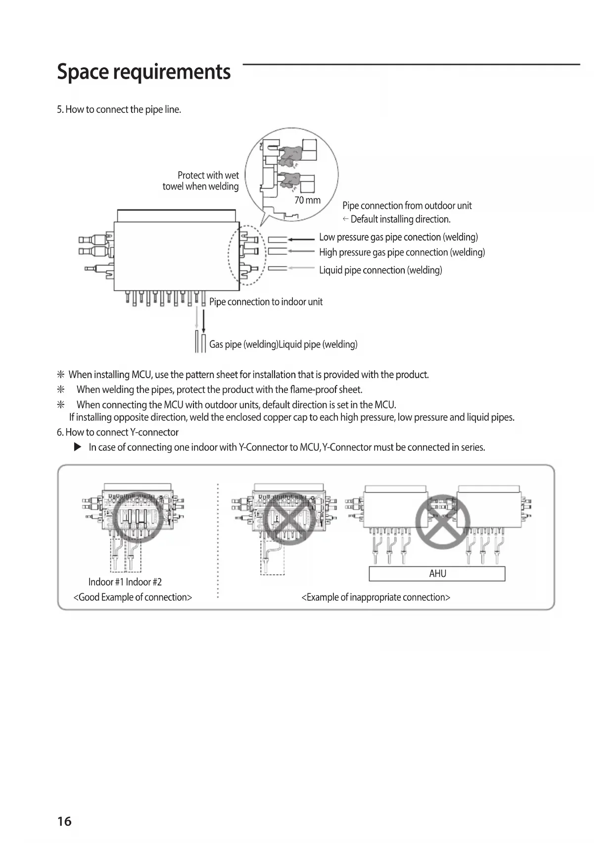
5. How to connect the pipe line.
Pipe connection from outdoor unit Default installing direction. Pipe connection to indoor unit Gas pipe (welding)Liquid pipe (welding) Protect with wet towel when welding 70 mm Low pressure gas pipe conection (welding) High pressure gas pipe connection (welding) Liquid pipe connection (welding) J When installing MCU, use the pattern sheet for installation that is provided with the product. J When welding the pipes, protect the product with the ame-proof sheet. J When connecting the MCU with outdoor units, default direction is set in the MCU. If installing opposite direction, weld the enclosed copper cap to each high pressure, low pressure and liquid pipes.
6. How to connect Y-connector
X In case of connecting one indoor with Y-Connector to MCU, Y-Connector must be connected in series. <Good Example of connection> Indoor #1 Indoor #2 <Example of inappropriate connection> AHU ki]_TW]`WZhTW\pttj|GrniluRmyUGGGX] YWYYTXXTYYGGG㝘㤸G_a\_a\`17 Pipe brazing instructions and cautions Keeping refrigerant pipe clean and dry X To prevent foreign materials or water from entering the pipe, it is important to keep the refrigerant pipe clean, dry and sealed during installation. Exposure place Exposure time Sealing type Outside exposure Longer than one month Pipe pinch Shorter than one month Taping Inside exposure - Taping Brazing the pipe X Make sure that there is no moisture inside the pipe. X Make sure that there are no foreign materials and impurities in the pipe. X Make sure that there is no leak. X Make sure to follow the instruction when brazing the pipe. The use of Nitrogen gas
1. Use Nitrogen gas when brazing the pipes as shown in the picture.
2. If you don’t use Nitrogen gas when brazing the pipes, oxide may form
inside the pipe. It can cause the damage of the compressor and valves.
3. Adjust the ow rate of the nitrogen gas with a pressure regulator to
maintain 0.05m/h(1.77ft/h) or less. Direction of the pipe when brazing
- Performing the brazing of the pipe should be headed downwards or horizontally. Brazing part 1/4" copper pipe Stop valve Taping Pressure regulator Nitrogen gas Flowmeter Refrigerant piping ki]_TW]`WZhTW\pttj|GrniluRmyUGGGX^ YWYYTXXTYYGGG㝘㤸G_a\_a\`18 Refrigerant piping Pipe insulating instructions and cautions Make sure to check for gas leakage before completing the installation (hose and pipe insulation) and insulate hoses and pipes when there is no sign of leakage.
1. To avoid condensation problems, place T13.0 (1/2") or thicker Acrylonitrile
Butadien Rubber separately around each refrigerant pipe. No gap NBR(T13.0(1/2") or thicker) CAUTION
- When installing pipe insulation, make sure that the insulation seam is on the top of the pipes.
2. Wrap insulating tape around the pipes. Avoid compressing the pipe insulation
3. Finish wrapping insulating tape around the rest of the pipes leading to the
4. Pipes and electrical cables connecting the unit with the outdoor unit must be
secured to the structure with appropriate straps/hangers.
- L'ajustement doit être eectué fermement contre le corps, sans aucun espace. CAUTION
- Must t tightly against body without any gap. Insulation cover pipe Insulation pipe Indoor unit Be sure to overlap the insulation
- Tous les raccords des tuyaux de réfrigérant doivent être accessibles an de permettre l'entretien de l'appareil ou son retrait complet. CAUTION
- All refrigerant connection must be accessible, in order to permit either unit maintenance or removing it completely.
5. Select the insulation of the refrigerant pipe.
X Insulate the gas side and liquid side pipe referring to the thickness according to the pipe size. X Indoor temperature of 30°C(86°F) and humidity of 85% is the standard condition. If install in a high humidity condition, use one grade thicker insulator by referring to the table below. If installing in an unfavorable conditions,use thicker one. X Insulator’s heat-resistance temperature should be more than 120°C(248°F). Pipe Outer diameter Insulator (Cooling, Heating) Remarks General [30°C (86°F) , 85%
ki]_TW]`WZhTW\pttj|GrniluRmyUGGGX_ YWYYTXXTYYGGG㝘㤸G_a\_a\`19 Refrigerant pipe before EEV kit and MCU or without EEV kit and MCU X You can contact the gas side and liquid side pipes but the pipes should not be pressed. X When contacting the gas side and gas side pipe, use 1 grade thicker insulator. Gas pipe Liquid pipe Insulation Insulation Refrigerant pipe after EEV kit and MCU X Install the gas side and liquid side pipes, leave 10mm(3/8") of space. X When contacting the gas side and liquid side pipe, use 1 grade thicker insulation. Gas pipe 10mm(3/8") Liquid pipe 10mm(3/8") 10mm(3/8") Insulation for non-serial connection of MCU X Exposed pipes should be insulated. Exposed pipes on non-serial connection CAUTION
- Prevent insulation thickness from getting thinner at the pipe hanger. Use adhesives on the seams to prevent moisture from entering.
- Wrap the refrigerant pipe with insulation tape if it is exposed to outside sunlight.
- Install the refrigerant pipe ensuring that the insulation does not get thinner on the bent part or hanger of pipe.
- Add the additional insulation if the insulation plate gets thinner. Additional insulation Hanger Refrigerant pipe insulation a×3
J x [A] ≥ 1.25 X 1.1 X ∑Ai (x [A] : MCCB/ELB ampheres, ∑Ai : Sum of the rated current ampheres of indoors) Installing the wire X Supply the 220-240V/208-230V power to L1, L2 (L, N) of MCU separately X Connect the communication cable from the outdoor unit to F1, F2 of MCU. X Power Line and communication line must be connected as shown in drawing. Case 1 Case 2 220-240V/208-230V / Single Phase (Supply separately) ELB MCCB Outdoor Unit Indoor Unit Indoor Unit MCU ELB MCCB Outdoor Unit Indoor Unit Indoor Unit MCU Indoor Unit 220-240V/208-230V / Single Phase (Supply separately) MCU Case 3 ELB MCCB Outdoor Unit Indoor Unit MCU Indoor Unit Indoor Unit 220-240V/208-230V / Single Phase (Supply separately) Indoor Unit ki]_TW]`WZhTW\pttj|GrniluRmyUGGGYW YWYYTXXTYYGGG㝘㤸G_a\_a\`21 X Power line and communication line must be installed as shown in drawing J Hole size is Φ 43.7 mm (1.72 inches) Hole for MCU main power supply Hole for communication Hole for MCU main power supply Hole for communication Hole for MCU main power supply Hole for communication X Choose the compressed socket based on the cross-section of the connecting wire. Silver solder Nominal dimensions for cable [mm
(inch2)] 1.5 (0.002) 2.5 (0.003) 4 (0.006) Nominal dimensions for screw [mm (inch)] 4 (0.157) 4 (0.157) 4 (0.157) 4 (0.157) 4 (0.157)
Standard dimension [mm (inch)] 6.6 (0.259) 8 (0.314) 6.6 (0.259) 8.5 (0.334)
Allowance [mm (inch)] ±0.2 (0.007) ±0.2 (0.007) ±0.2 (0.007)
Standard dimension [mm (inch)] 3.4 (0.134) 4.2 (0.165)
Allowance [mm (inch)] +0.3 (0.011) -0.2 (-0.007) +0.3 (0.011) -0.2 (-0.007) +0.3 (0.011) -0.2 (-0.007)
Allowance [mm (inch)] +0.2 (±0.007)
E Min. [mm (inch)] 4.1 (0.161) 6 (0.236) 6 (0.236) F Min. [mm (inch)] 6 (0.236) 6 (0.236) 5 (0.196) L Max. [mm (inch)] 16 (0.629) 17.5 (0.688) 20 (0.787)
Standard dimension [mm (inch)] 4.3 (0.169) 4.3 (0.169)
Allowance [mm (inch)] +0.2 (±0.007)
t Min. [mm (inch)] 0.7 (0.027) 0.8 (0.031)
ki]_TW]`WZhTW\pttj|GrniluRmyUGGGYX YWYYTXXTYYGGG㝘㤸G_a\_a\`22 Wiring Setting MCU address and port J When counting the quantity of MCUs while outdoor unit installation, one MCU is one. However, in the case of MCU-S12NEK1N and MCU-S8NEK1N, one MCU must be counted as two MCUs. Process
address setting Set MCU address by rotary switch. Example> If you want to set MCU address to 12, set upper rotary switch to 1 and set bottom rotary switch to 2
MCU Address Setting MCU adress to 12 Default MCU Address
Rotary switch for MCU ADDRESS J MCU-S12NEK1N & MCU-S8NEK1N models have two PBAs in the control box. The MCU addresses of the two PBAs must be set dierently. Example> If you set MCU addresss of the section #1 PBA to 11, then set the section #2 PBA address to 12. <Section #1> <Section #2>
MCU Address Setting MCU adress to 11
MCU Address Setting MCU adress to 12 Rotary switch for MCU ADDRESS Rotary switch for MCU ADDRESS ki]_TW]`WZhTW\pttj|GrniluRmyUGGGYY YWYYTXXTYYGGG㝘㤸G_a\`aWW23 Process
setting for using each port Set using each port (connected to indoor unit) by DIP switch Example> If you want to connect indoor units at A,B,C,F port, set DIP switch 1,2,3,2 to 'ON' DIP switch for indoor unit setting (ON: Use, OFF: Not use)
setting for using Y-connetor
[MCU-S6*, MCU-S4*, MCU-S2*, MCU-S1*]
When twinning 2 adjacent ports, Y-connectors can only be connected to the port combinations noted below. Allowed Y-connector port combinations: A + B, C + D, E + F ports Y-connector port combinations that are NOT allowed: B + C port, D + E port, any non-continuous port (example: A+C) Set Dip Switch Settings when using Y-connector
setting for using Y-connetor [MCU-S12*, MCU-S8*] When twinning 2 adjacent ports, Y-connectors can only be connected to the port combinations noted below.: [#1-A] + [#1-B] port, [#1-C] + [#1-D] port, [#1-E] + [#1-F] port [#2-A] + [#2-B] port, [#2-C] + [#2-D] port, [#2-E] + [#2-F] port Y-connector port combinations that are NOT allowed: #1 Ports: B + C port, D + E port, any non-continuous port (example: A+C) #2 Ports: B + C port, D + E port, any non-continuous port (example: A+C) Set Dip Switch Settings when using Y-connector Dip Switch Settings when using Y-connector Dip Switch Settings when using Y-connector
address and port setting for indoor unit (for wireless remote controller) Auto setting: refer to 'auto pipe pairing' in outdoor installation manual. Manual setting :
1. Wireless remote controller
1) Enter mode to set option
2) Assign an indoor unit MCU port address by wireless remote controller
Address setting mode
Group channel(*16) Group address Remote Controller Display Indication and Details Indication Details Indication Details Indication Details Indication Details
Setting MCU PORT address 10-digit of MCU The unit digit of MCU PORT address Remote Controller Display Indication and Details Indication Details Indication Details Indication Details Indication Details Indication Details
address and port setting for indoor unit (for wired remote controller)
2. Wired remote controller
– Setting for MWR-WE1*N
1) Press the Delete and Set buttons at the same time for more than three seconds. Then you will
enter the additional function settings, and the [main menu] will be displayed.
2) Assign an indoor unit MCU port address with main menu 4, sub menu 7 (MCU address is
assingned to SEG 12, Port address is assinged to SEG 4). If you want to know the detailed operation of MWR-WE1*N , refer to installation manual for MWR-WE1*N. Main Menu Sub- menu
Setting/Checking the product option MAIN address (00H~4FH) None
Setting/Checking the installation option 1 Refer to the installation manual of the connected indoor unit/ ventilator (ERV) None
Setting/Checking the installation option 2 None
MCU address setting/ checking Port address setting/ checking MCU address (00~15) Port address (A~F) None – Setting for MWR-SH1*N
1) Press the top right corner (hidden button) of the display for more than 3 seconds then release it.
Then you can press [ + ]/[ - ] buttons and select No.3 and press [ OK ] button.
2) Assign an indoor unit MCU port address with main menu 4, sub menu 7 (MCU address is
assingned to SEG 12, Port address is assinged to SEG 4). If you want to know the detailed operation of MWR-SH1*N, refer to installation manual for MWR-SH1*N. Setting value Main menu Sub menu Page Move menu Move page Main menu Sub menu Function Setting value value Factory default
Setting address/ option Target address setting Target address of indoor unit (Example: 20 02 1F) None 2 Main address setting/Checking 0~4F (in hexadecimal digits) 3 RMC address setting/Checking 0x00~0xFE None 4 Basic option setting/Checking Option code 5 Install option setting/Checking Option code None
MCU address setting/checking Port address setting/checking MCU address (00~15) Port address (A~F) None Wiring ki]_TW]`WZhTW\pttj|GrniluRmyUGGGY] YWYYTXXTYYGGG㝘㤸G_a\`aWX27 Process
address and port setting for indoor unit (for wired remote controller) – Setting for MWR-WG0**
and buttons at the same time for more than 3 seconds. Then you can enter the password(0202) and press the OK button.
2) Assign an indoor unit MCU port address with [Major] General Ꮡ [Step1] Indoor unit/
Ventilator option Ꮡ [Step2] MCU port Ꮡ [Step3] MCU address & MCU port. J For more information, please refer to the installation manual of MWR-WG0** Major Step1 Step2 Step3 Description General Indoor unit/ Ventilator option MCU port MCU address 00 to 15 MCU port A to F
Please enter your PASSWORDService mode
3. Setting by using S-NET Pro 2
Set the pipe addresses by using Add-on > Change address on S-NET Pro 2. (For more information, see the S-NET Pro 2 Help.) ki]_TW]`WZhTW\pttj|GrniluRmyUGGGY^ YWYYTXXTYYGGG㝘㤸G_a\`aWX28 Wiring NOTE
- The Direct-connected indoor unit without MCU like below picture, be sure to set their options to "Cooling only unit setting“ and then connect them to a low pressure gas pipe and a liquid pipe. This indoor unit only operate to cooling mode.
- If two or more indoor units are connected to a single port, switching between cooling and heating mode does not work while in auto mode. It is recommended to select the cooling or heating mode. MCU Direct-connected indoor unit without MCU (Connecting Only Low Pressure Gas Pipe / Liquid Pipe) Connecting two or more indoor units to a single port Set to Cooling Only Unit
1. Check whether power is supplied or not.
– When the indoor unit is not plugged in, there should be additional power supply in the indoor unit.
2. The panel(display) should be connected to an indoor unit to receive option.
3. Enter mode to set option (J Detail method of entering option mode refer to indoor unit installation manual)
4. Set the 05 series installation option at SEG3 to '2' like this '052000 - 100000 - 20000 - 30000'.
(The default setting of an indoor unit 05 series installation is '050000 - 100000 - 20000 - 30000')
- When setting the "Cooling only unit" option, be sure to set the SEG 9 (Hot water heater) of 02 Series installation to "0".
- When "Cooling only unit" option is set, heating operation is not performed when the controller (wireless remote controller, central controller) is set to the heating mode. Option No. : 05XXXX-1XXXXX-2XXXXX-3XXXXX Option SEG1 SEG2 SEG3 SEG4 SEG5 SEG6 Explanation PAGE MODE Use of Auto Change Over for HR only in Auto mode / Cooling only unit setting (When setting SEG3) Standard heating temp. Offset (When setting SEG3) Standard cooling temp. Offset (When setting SEG3) Standard for mode change Heating Cooling Remote Controller Display Indication and Details Indication Details Indication Details Indication Details Indication Details Indication Details Indication Details
Follow product option
Cooling only unit setting
Heating mode (When setting SEG3) Time required for mode change Compensation option for Long pipe or height diference between indoor units Remote Controller Display Indication and Details Indication Details Indication Details Indication Details Indication Details
is 50~110m 5 3.5 5 15 min. 6 4 6 20 min. 7 4.5 7 30 min. J MCU-S12NEK1N & MCU-S8NEK1N models have two PBA in the control box. There are two sections in the MCU. So, key operation must be set dierently for each section. Key operation K1 K2 K3 K4 Display MCU status Display indoor unit's address Solenoid valve manual control
Blank 0 0 MCU address 0 Blank 0 1 MCU address 1 Blank 0 2 MCU address 2 Blank 1 1 MCU address 11 Blank 1 5 MCU address 15
Subcooler-in sensor temperature
Subcooler-out sensor temperature
On/O for solenoid valve A_C, A_H
- 4th segment : Heating solenoid valve On : 1 / O : 0
On/O for solenoid valve B_C, B_H
On/O for solenoid valve C_C, C_H
On/O for solenoid valve D_C, D_H
On/O for solenoid valve E_C, E_H
On/O for solenoid valve F_C, F_H
On/O for liquid by pass solenoid valve
Version 8A20 Ex) October 20, 2008 → 8A 20
1 Indoor unit main address for matching with port A A - 0 0 Indoor unit main address of port A : 0 2 Indoor unit main address for matching with port B B - 0 3 Indoor unit main address of port B : 3 3 Indoor unit main address for matching with port C C - 0 6 Indoor unit main address of port C : 6 4 Indoor unit main address for matching with port D D - 0 9 Indoor unit main address of port D : 9 5 Indoor unit main address for matching with port E E - 1 1 Indoor unit main address of port E : 11 6 Indoor unit main address for matching with port F F - 1 5 Indoor unit main address of port F : 15 7 End of K2 display J When two or more indoor units are connected to one port, Indoor unit addresses are sequentially displayed at 2-second intervals from the lowest address indoor unit. (After displaying all, display the rst indoor unit again) K4 Switch (Solenoid Valve Manual Control) X According to the push time of K4 Switch, A_C, A_H, …, F_C, F_H, Liquid bypass solenoid valve opens in order. X In Solenoid Valve Manual Control mode, valve operates by K4 Push time irrespective of indoor operation mode. X In Solenoid Valve Manual Control mode, push K1 Switch makes DATA DISPLAY MODE to start and valves will operate following indoor operation mode.
1 A_C sol valve ON, other sol valve O P A 1 0 2 A_H sol valve ON, other sol valve O P A 0 1 3 B_C sol valve ON, other sol valve O P B 1 0 4 B_H sol valve ON, other sol valve O P B 0 1 5 C_C sol valve ON, other sol valve O P C 1 0 6 C_H sol valve ON, other sol valve O P C 0 1 7 D_C sol valve ON, other sol valve O P D 1 0 8 D_H sol valve ON, other sol valve O P D 0 1 9 E_C sol valve ON, other sol valve O P E 1 0 10 E_H sol valve ON, other sol valve O P E 0 1 11 F_C sol valve ON, other sol valve O P F 1 0 12 F_H sol valve ON, other sol valve O P F 0 1 13 Liquid b/p sol valve ON, other sol valve O P S 1 0 14 sol valve Manual Control MODE end P Communication DATA Display ki]_TW]`WZhTW\pttj|GrniluRmyUGGGZW YWYYTXXTYYGGG㝘㤸G_a\`aWX31 MCU Installation Checklist Item Check
1. If the gas leaking test has been completed or not.
2. If MCU has been xed securely enough to avoid the danger of vibration and falling or not.
3. The Insulation condition of the pipe. (Refrigerant pipe, Pipe connection.)
4. If the R-410A refrigerant has been charged or not.
If the subsidiary unit for R-410A has been used or not.
5. Checking malfunction of the wire and the communication line.
6. If the MCU frame has been installed upside-down or not.
7. If the wire earthing work has been done or not.
8. If the space between sidewalls, ceiling concrete, and the ceiling Tex has been secured enough or
not to install the MCU frame.