HL 42550 - Compressor Airpress - Free user manual and instructions
Find the device manual for free HL 42550 Airpress in PDF.
| Title | Description |
|---|---|
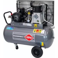
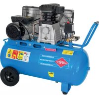
| Type of compressor | Piston compressor |
| Maximum pressure | 8 bars |
| Airflow | 200 L/min |
| Tank capacity | 50 liters |
| Power | 2.5 kW |
| Power supply | 230 V |
| Weight | 40 kg |
| Dimensions | 90 x 40 x 75 cm |
| Recommended use | Ideal for DIY, painting and inflating tasks |
| Maintenance | Regularly check oil level and air filter |
| Safety | Use personal protective equipment (PPE) when operating |
| Warranty | 2 years |
Frequently Asked Questions - HL 42550 Airpress
Download the instructions for your Compressor in PDF format for free! Find your manual HL 42550 - Airpress and take your electronic device back in hand. On this page are published all the documents necessary for the use of your device. HL 42550 by Airpress.
USER MANUAL HL 42550 Airpress
5.0 Operation page 22
6.0 Maintenance page 23
7.0 Possibilities of failure page 24
be able to use this compressor installation properly, a number of mea- surements must be taken. The following points will contribute to making you a satisfied user of this installation.
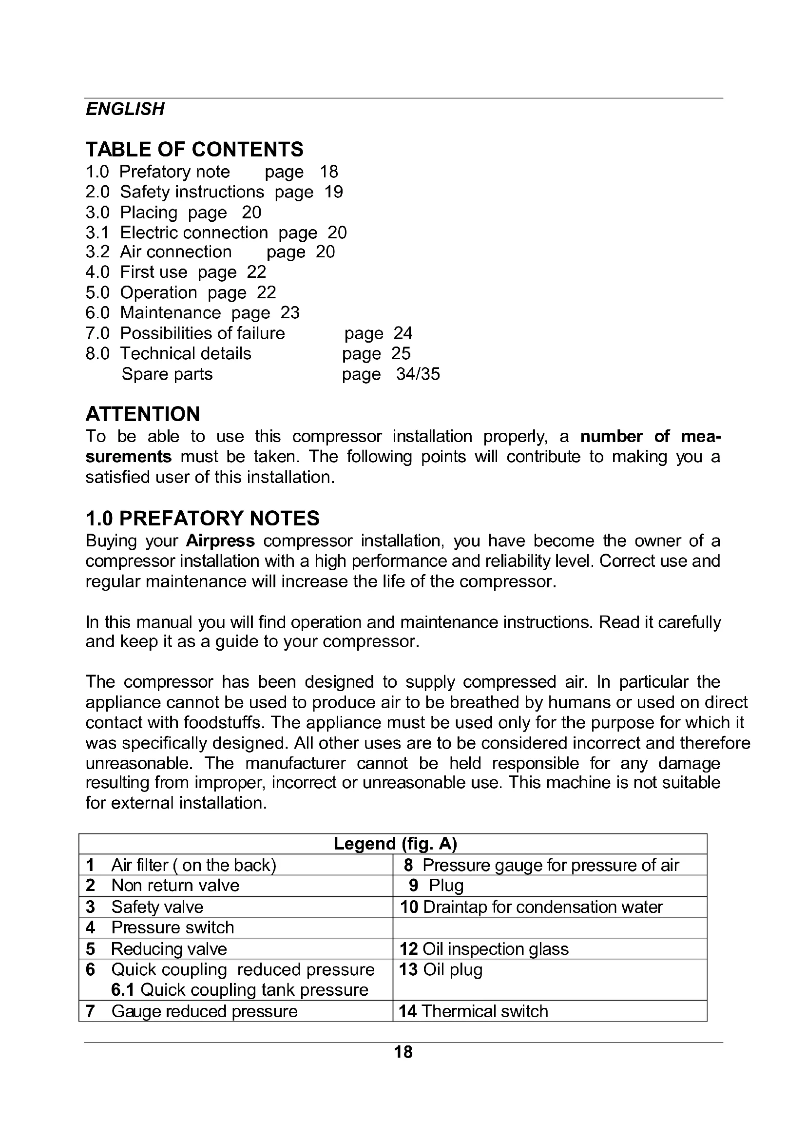
0 PREFATORY NOTES Buying your Airpress compressor installation, you have become the owner of a compressor installation with a high performance and reliability level. Correct use and regular maintenance will increase the life of the compressor. In this manual you will find operation and maintenance instructions. Read it carefully and keep it as a guide to your compressor. The compressor has been designed to supply compressed air. In particular the appliance cannot be used to produce air to be breathed by humans or used on direct contact with foodstuffs. The appliance must be used only for the purpose for which it was specifically designed. All other uses are to be considered incorrect and therefore unreasonable. The manufacturer cannot be held responsible for any damage resulting from improper, incorrect or unreasonable use. This machine is not suitable for external installation. Legend (fig. A) 1 Ai r filter ( on the back) 8 Pressure gauge for pressure of air 2 No n return valve 9 Plug 3 Sa fety valve 10 Draintap for condensation water 4 Pr essure switch 5 Reducing valve 12 Oil inspection glass 6 Quick coupling reduced pressure
6.1 Quick coupling tank pressure
13 Oil plug 7 Ga uge reduced pressure 14 Thermical switch19
portant: please read and observe the following safety instructions before
ing the machine. Nobody must be allowed to use the compressor unless they have read the instruction manual and have been instructed in the regulations to follow for correct and safe use. The machine must be used by adults only. Use of the compressor by apprentices of not less than 16 years of age must be supervised by an adult authorised to use the machine. Keep children and visitors away from the working area. Be cautious when using compressed air. Never aim the air flow at people or animals. Do not use compressed air to clean clothing. Compressed air is not suitable to inhale. Do not wear loose clothing or neckties that can get caught in moving parts. Preferably wear safety goggles, nonslip footwear and Wear protective hair covering to contain long hair. Only use the machine outside in dry, well-ventilated surroundings and do not expose the machine to rain. The compressor should be placed in such way that all points, destined to carry it will really do so. Take also care of a horizontal position. This machine is not fit for continuous running, but service for 30% per 60 minutes (S3). Keep your work area clean and well lighted. Do not use the machine in areas where fumes from paint, solvents or flammable liquids pose a potential hazard. Do not exceed the maximum operating pressure and only use the machine in an ambient temperature between +5ºC and +40ºC. Never attempt to tamper with the protections of the log splitter or to operate the machine without these. The working parts of the machine can become hot during operation. Let the machine cool down after use. After each use the tank must be vented and the moisture collected in the tank must be bled. Not bleeding the tank can lead to leakage and may cause a dangerous situation. Check that the electric circuit is adequately protected and that it corresponds with the power, voltage and frequency of the motor. Check that there is a ground connection and a regulation differential switch upstream. Use cables with an adequate section and avoid use of free and inadequately insulated connections (see also 3.1) Never open the pushbutton box on the motor. Should this be necessary, contact a qualified electrician. Make sure that the machine and the cable never come in contact with water. Treat the power cable with care. Do not attempt to move the machine by pulling the cable. Do not yank the cable to unplug it; keep the cable away from excessive20 heat, oil and sharp objects. Never leave the machine unattended with the power supply "on". Also disconnect the power cable when: - you leave the machine, even for a short time - not in use - carrying out maintenance work - changing attachment or moving the machine.
WARNING: the warnings, cautions and instructions discussed in this
instruction manual cannot cover all possible conditions and situations that may occur. It must be understood by the operator that common sense and caution are factors which cannot be built into this product, but must be supplied by the operator. Only those persons who are aware of how to use the compressor by having read this manual, should use the machine. Injudicious use may cause danger.
nger plates The plates fitted on the compressor unit are part of the machine; they have been applied for safety purposes and must not be removed or spoiled for any reason. See page 34 for explanation.21
PLACING The compressor should be placed in such way that all points, destined to carry it will really do so. Take also care of a horizontal position. The engine should get sufficient cooling air; so never cover the ventilating openings. Place the compressor in a cool dustfree space. Never place the compressor in a room where will be sprayed. Paint spray will clog the air filter and will also deposit on the compressor. Mind that the draintap for condensation water (10), the oil drain plug (11) and the oil plug (13) will always remain attainable. We suggest to leave a space of aproximately 50 cm for ventilation and maintenance. Notice: Insufficient air supply, too high temperature and fouling of the air filter reduce the efficiency of the compressor considerably.
ELECTRIC CONNECTION At the factory the machine is already fully equipped with cables. The machine now has to be connected to your own electricity supply. Connect the machine to a separate group. Beware that voltage and amperage of your electric circuit meet the needs of the motor. Use only cables with the right diameter. The factory suggests to use cables of at least 2.5 qmm, length max. 10 m. Before first use first read chapters 3.2 and 4.0.
st use for connection of the compressor to an air circuit a flexible hose, to isolate fibrations from the machine. The coupling No 6 is a universal Orion/Airpress quick coupling.22
1. Check if the instructions mentioned above have been executed.
2. On delivery the compressor mostly is not filled with oil. Fill about 0,5 litres
compressor oil until the red circle on the oil inspection glas (12).
3. Install the air filter (1) in the cylinder heads (first remove the synthetic plug).
4. Install the oil filler cap (13) on the crank case lid (first remove the synthetic plug).
5. Avoid the use of extension cables. If you use them, unroll them completely and
use cables of sufficient capacity. Tabel for extension cables:
itch on the compressor by means of pulling the pressure switch (4). The compressor will now operate, unless the air receiver is still under pressure (pressure gauge 8). Switch the machine, during operation, exclusively off by means of pushing the button on the automatic pressure switch (4); the pressure circuit will be vented and the compressor can start again uncharged. After use shut down the compressor by pushing the button on the automatic pressure switch (4) and then pull the plug from the power supply.
The automatically operating compressor will stop at a pressure of 8 bar (8). When air is used again and the pressure in the tank falls to 6 bar, the compressor will start again.
2. Most pneumatic machines are suitable for an operating pressure of about 6 bar.
For some applications this pressure is even lower. To be able to set the right pressure, the compressor is provided with a reducing valve (5). This valve can set the pressure of the air receiver (of course never higher than the pressure in the air receiver).
3. The setting of the reducing valve is done as follows: switch the button to set the
right pressure (to the left to lower the pressure, to the right to increase it). The setting pressure is shown at the gauge (7).
4. Two extra plugs (9) are fitted to the tank, which can be used to get an extra
pressure connection.
5. Two quick couplings are mounted, no. 6 is reduced pressure and no. 6.1 is tank
MAINTENANCE Before carrying out any maintenance jobs it is obligatory to stop the machine, disconnect it from the power mains and make sure that the tank is pressure free by opening the condensation draintap (10).
1. After the first 50 operating hours and then every 250 operation hours the oil
should be refreshed. Turn off the oil drain plug (11) and also remove the filler cap (13). Collect the oil. If the oil does not come out any longer, switch on the drainplug again and refill the oil (through fillercap) until the oil has reached the correct level (0,5 liter) The right oil level is on the red circle on the oil leveler (12). Always respect the regulations in force for disposing of old oil!
2. Regularly drain condensation water. The draintap is situated at the bottom of the
tank (10). Draining with pressure in the tank is the easiest way. Some compressors have an aftercooler with its own drainplug. Also from this device the condensationwater should be drained regularly. Condensate must be disposed of in conformity with the local regulations in force (not in the sewer!). As an alternative you can place an oil/water separator.
3. The oil level should also be checked regularly. For the right oil level see point 1. If
necessary refill with compressor oil, order No 12491 (0,6 l l) or order No 12492 (1 l). Checking daily can prevent a lot of troubles! Use oil of the same type as that already in the machine; do not mix different types of oil!
4. The air filter element (1) should be cleaned or changed regularly. This change
depends on the amount of fouling and should be done more often in dusty situations and less often in a clean situation. For cleaning the filterelement, take out the filtercontainer with the filter. Then clean the filter by blowing off the dust. Note: Regular maintenance of your compressor will increase durability and reliability. MAINTENANCE TABLE works daily weekly every every
refre sh oil (first time afte r 50 hours) ▀24
1 Compressor does not run at starting pressure:
- blown fuse - renew the fuse
- tank at pressure - discharge
- motor broken - repair/renew
- defective pressure switch - repair/renew (no. 4)
- thermic fall out - reset protection 2 Repeating thermal failure:
- blown fuse - renew fuse
- pressure switch does not releave - repair/renew valve air circuit
- too low voltage - remove extension cable or use heavier
- overloading - reduce loading 3 Compressor keeps blowing off air:
- defective non-return valve - repair/renew (no. 2) 4 Too little air production:
- dirty air filter - clean/renew filter (no. 1)
- defective valves - renew 5 Leaking safety valve:
- pressure too high - set pressure switch (no. 4)
- defective safety valve - renew (no. 3)25
mber of cylinders 2 Number of stages 1
otected with 16 amp.
mensions (lxwxh) 770x380x750 mm Mod elchanges reserved. All compressors are provided with Euro-Norm (CE-Choice)26 FRANÇAIS
NO Desi gnation Qty NO Designation Qty 1 BoltM 6x55 4 38 stator 1 2 cylinder head 1 39 rotor 1 3 cylinder head gasket 2 40 brearing 6202 1 4 valve pl ate 2 41 wave washer D35 1 5 valve pl ate gasket 2 42 Leave the heart switch scaleboard 1 6 valve cl ack 2 43 Leave the heart switch 1 7 Sel l the son 4 44 The electrical engineering cover 1 8 cyli nder 2 45 Lead the breeze cover blocks the plank 1 9 cyli nder gasket 2 46 bolt M5x30 6 10 piston r ing 4 47 Breeze leaf 1 11 Oil wreath 2 48 Block the turn 14 1 12 piston 2 49 Lead the breeze cover 1 13 piston pin 2 50 From offend the bolt ST4.8x16 5 14 circl ip 4 51 The high pressure tube 1 15 conncting r od 2 52 Nut M8 4 16 rubber gasket 1 53 Unload the lotus tube 1 17 crank case cover 1 54 The outside is hexangular bolt M8x25 4 18 bolt M 5x16 6 55 One-way valve 1 19 oil l eveler gasket 1 56 Axle 2 20 oil l eveler 1 57 Axle set 2 21 bolt M6x10 1 58 Wheel 2 22 O circlip φ5.6xφ1.8 1 59 Block up the head 2 23 hex bolt M8x22(left) 1 60 Nut M10 2 24 crank 1 61 Even m at 4 25 crank case 1 62 The catchment fill 1 26 bolt M6x 40 8 63 The outside is hexangular bolt M8x25 2 27 seali ng ring 1 64 Rubber mat 2 28 breari ng 6204 1 65 Defend the loose nut M8 2 29 Start t he electric capacity 1 66 Combine the tight nut 1 30 Nut M8 2 67 The support is total to become 1 31 Revolve the electric capacity 1 68 Safe valve 1 32 Prop up the plank 1 69 Quickly change to deal with contact 2 33 bolt M8x 25 4 70 Manometer 2 34 Direct shipping links 1 71 Pressure switch 1 35 Conne ct the connector 1 72 Plug line 1 36 Curve d head of right angle 1 73 Rubber hand handle 1 37 Elim inate the sound machine 2 7437