
H4.115 - Marine engine Nanni - Free user manual and instructions
Find the device manual for free H4.115 Nanni in PDF.
| Product type | 4-stroke marine diesel engine |
| Brand | Nanni |
| Model | H4.115 |
| Rated power | 84.6 kW (115 hp) at 3000 rpm |
| Number of cylinders | 4 in line |
| Displacement | 1991 cc |
| Bore / stroke | 83 x 92 mm |
| Compression ratio | 17.5:1 |
| Fuel system | Common Rail direct injection (Bosch CRS 2.0), pressure 1600 bar |
| Injection order | 1-3-4-2 |
| Lubrication | Forced by rotor pump |
| Engine oil capacity | 3.2 L (min) - 4.2 L (max) |
| Oil pressure (minimum speed) | 1 - 4 bar |
| Cooling | Closed circuit with heat exchanger, water + antifreeze 50/50 mixture |
| Coolant capacity | 7.7 L |
| Expansion tank cap setting pressure | 1.2 bar |
| Electrical system | 12 V, alternator 110 A, starter 2 kW |
| Recommended battery | 100 - 120 Ah |
| Weight (without transmission) | 250 kg |
| Maximum rated speed under load | 3000 ± 50 rpm |
| Idle speed | 700 ± 50 rpm |
| Theoretical fuel consumption | 21.8 L/h at 3000 rpm |
| Number of valves | 4 per cylinder, hydraulic lifters |
| Main functions | Marine propulsion, speed control and reverser, dashboard with alarms |
| Safety | Emergency stop by fuel cutoff, zinc sacrificial anodes, protective fuses, alarms (oil pressure, temperature, water in diesel) |
| Routine maintenance | Oil change, filter replacement (oil, diesel, air), level checks, fuel system bleeding, cleaning sea water filter |
| Spare parts and repairability | Genuine Nanni Diesel parts available from authorized dealers |
| Warranty | Valid subject to maintenance by a Nanni Diesel authorized technician |
| General information | 64-page user manual, available for free download |
Frequently Asked Questions - H4.115 Nanni
User questions about H4.115 Nanni
0 question about this device. Answer the ones you know or ask your own.
Ask a new question about this device
Download the instructions for your Marine engine in PDF format for free! Find your manual H4.115 - Nanni and take your electronic device back in hand. On this page are published all the documents necessary for the use of your device. H4.115 by Nanni.
USER MANUAL H4.115 Nanni
Marine Diesel engines
H4.115
H4.130
H4.150
H4.170
Contents
Safety precautions 3
Presentation 6
Identification plates 6
Additional equipment 6
Warranty 7
Environmental responsibility 7
Preparations before starting. 7
Fuel supply. 7
Behaviour of the boat. 7
Instrument panel 8
Warning lights & alarms.. 9
Throttle lever 9
Principal parts of the engine 10
Installation inspection 11
Operation of the engine 12
Before starting 12
Starting the engine 12
During operation 13
Forward / reverse speed 13
Running in 13
Stopping the engine 13
Emergency stop 13
After the engine has stopped 13
Maintenance 14
Daily checks 15
Fuel system 16
Bleeding the fuel circuit 16
Replacing the fuel filter. 16
Replacing the fuel prefilter. 17
Draining the water from the fuel prefilter 17
Lubrication circuit 18
Checking the oil level 18
Replacing the oil filter cartridge 18
Draining the engine oil 19
Cooling circuit - coolant 20
Coolant filling. 21
Draining the cooling circuit 21
Rinsing the cooling circuit 21
Cooling circuit - seawater 22
Cleaning the seawater filter 22
Draining the seawater circuit 22
Replacing the seawater pump rotor 23
Air filter 24
Engine electrical system. 25
Check the electrolyte level 25
Changingfuses 25
Protection against corrosion - Zinc anode 26
Protecting the engine during periods of inactivity 27
Restarting the engine 27
Fault-finding 28
Technical specifications 30
Safety precautions
Read this chapter carefully as it concerns your safety. Most accidents are caused by failing to follow basic safety rules.
Be aware of the possible risks involved in handling your engine and make sure you take the necessary precautions to protect yourself, those around you and your equipment.
This manual contains important safety indications and information.
They are as follows:
Danger! : This symbol indicates the risk of accidents and serious personal injury, substantial property damage or serious mechanical faults if the instructions are not followed.
Attention! : Indicates a risk of personal injury and/or property damage when handling a component.
Remark: Indicates that important information must be known in order to facilitate handling or in particular cases.
Using and handling an engine entails risks that could prove to be extremely dangerous. Some work requires specific knowledge and equipment. This work should be carried out by Nanni Diesel authorised personnel or by a professional. If you have to work on the engine, carefully follow the safety instructions set down in this manual.
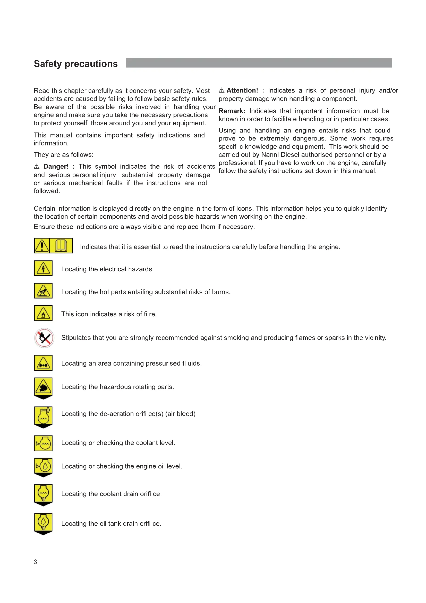
Certain information is displayed directly on the engine in the form of icons. This information helps you to quickly identify the location of certain components and avoid possible hazards when working on the engine.
Ensure these indications are always visible and replace them if necessary.

Indicates that it is essential to read the instructions carefully before handling the engine.

Locating the electrical hazards.

Locating the hot parts entailing substantial risks of burns.

This icon indicates a risk of fire.

Stipulates that you are strongly recommended against smoking and producing flames or sparks in the vicinity.

Locating an area containing pressurised fluids.

Locating the hazardous rotating parts.

Locating the de-aeration orifi ce(s) (air bleed)

Locating or checking the coolant level.

Locating or checking the engine oil level.

Locating the coolant drain orifice.

Locating the oil tank drain orifice.
Exhaust gas
Exhaust gases contain carbon monoxide. This colourless and odourless gas is extremely harmful and could lead to poisoning which could result in loss of consciousness or death. The first symptoms of carbon monoxide intoxication are as follows:
Dizziness
- Nausea
- Headache
Throbbing temples
Vomiting
Fatigue and falling asleep
Tense muscles
If you or anyone else in the vicinity of the engine experiences any of these symptoms, leave the area of operation of the engine and fi nd fresh air. If the symptoms persist, consult a doctor and have your engine checked.
Risk of electric shock
Never touch the electrical connectors when the engine is operational. The voltage at the connector terminals can be lethal.
Do not work on the engine without protection: protective goggles and gloves, insulating blankets etc.
Always disconnect the engine and cut the current before working on the electrical system. Isolate the shore power supply to all the electrical circuit equipment.
Ensure your clothing and skin is not damp or sweaty when handling electrical equipment. Remove watches, bracelets and jewellery when working on electrical equipment.
Handling a capacitor that is still charged can be dangerous and cause electrocution.
Risk of burns
Never touch the hot parts of the engine or the exhaust circuit.
An operational engine gets very hot: the exhaust elbow and pipe, turbocompressor, starter, oil sump, oil, coolant in the hoses and pipes are hot and can burn.
Always check the coolant level before starting the engine.
Fluids ejected under pressure can cause serious injury.
Release all the pressure in the circuits before removing the caps.
Never open the coolant and oil circuit caps when the engine is operational and/or hot.
Never start or run the engine when the oil fill cap is not screwed on as hot oil could spray out.
If you come into contact with any of these fluids, consult a doctor immediately.
If the engine gets too hot, switch it off and disconnect it and wait for it to cool down before handling.
Risk of fire
Do not smoke near the engine and keep it away from sources of ignition (fl ames or sparks) or any other potential flammable vapour or liquid sources.
Do not run the engine without an air fi ler.
Do not run the engine in an area in which flammable or explosive materials are stored or where gas is present. Ensure there are no flammable liquids in the engine compartment.
Immediately clean up any liquids spilled over yourself or the floor and keep the engine compartment clean and accessible so as to minimise the risk of fire. Be careful as fuel can burn.
Risk of explosion
Explosions caused by fuel vapour can cause serious injury! Carefully follow the safety rules when fliling the fuel.
Open and ventilate the storage area of the engine after fi lling. Check that there are no fuel vapours or leaks before starting the fan (if fitted). Switch the fan on for 5 minutes before starting the engine.
All fuel vapours are flammable and explosive. Be careful when handling and storing fuel. Store the fuel in a ventilated area away from sources of ignition (sparks or fl ames) and out of the reach of children.
Stop the engine before flling with fuel or lubricant. Do not smoke near the engine and keep it away from sources of ignition (flames) when filling with fuel and/or lubricant. Wear gloves when investigating possible leaks.
Do not alter or damage the fuel circuit. Close the fuel circuit whenever you work on it.
Ensure you always have an appropriate working extinguisher to hand.
Accidental starting
Accidental starting can cause serious injury and even death! Disconnect the battery before working on the engine.
Ensure no one is alongside the engine or working on the gearbox, the shaft line and / or the propeller before starting it.
Ensure all the protection mechanisms are in place before starting the engine.
Risk of battery explosion
A battery explosion can cause serious injury and even death!
Do not smoke near the batteries and keep them away from sources of ignition (fl ames or sparks). They produce hydrogen which could ignite or explode on contact with an electrical arc or a flame. Switch off all electrical appliances in the vicinity when you are working on the batteries. Ensure the battery storage compartment is corrected ventilated.
Avoid touching the battery terminals with metal tools so that no sparks are created which could cause an explosion. Remove your rings, bracelets and necklaces before handing the batteries.
Battery acid
The acid in batteries can cause serious injury and even death!
When servicing the batteries, wear protective gloves and goggles. Batteries contain sulphuric acid which is highly corrosive.
Acid can spurt from batteries when they are handled. If the acid comes into contact with the skin, rinse thoroughly in fresh water and consult a doctor.
Exhaust gas
Ensure the exhaust circuit correctly expels the gas produced by the engine.
Regularly check that the exhaust circuit is free of leaks and that the exhaust elbow is correctly affixed.
Operate the engine in a well aerated and ventilated area away from other people. Run the fan when the engine is operational.
Rotating parts
Rotating parts can be extremely dangerous and cause serious injury and even death!
Do not work on the engine when it is operational. If work on the engine when running is absolutely necessary, do not touch any hot or rotating parts.
Baggy clothing, hair or objects could be pulled in and/or caught and cause serious injury or substantial property damage.
Do not wear bracelets, necklaces or rings when working on the engine.
Check that the bolts and screws are properly tightened and that the protection mechanisms are in place.
Do not check the fluid levels or tension of the alternator belt when the engine is operational.
Lifting the engine
To lift the engine, use the hoisting eyes on the appliance.
Always check the robustness and overall condition of the lifting equipment. Use suitable gear (cables, beams, machines, etc.) to lift your engine. Check that your gear is capable of lifting the engine all the equipment that are mounted on the engine.
Lifting cables and chains must be able to move parallel to each other.
Do not forget that any additional equipment mounted on the engine could alter its centre of gravity. When lifting the engine, it should remain as parallel as possible to the ground.
Maintenance and spare parts
Nanni Diesel engines are designed to meet the different emission standards while delivering maximum service life and reliability.
Regularly servicing and replacing parts with original Nanni Diesel parts will ensure the engine continues to function optimally.
These parts can be ordered from all Nanni Diesel dealers throughout the world.
Chemical products
The different fluids used to run the engine are a health hazard.
Carefully read the instructions on the packaging of these products and always check that the ventilation in the hold space is adequate.
Thank you for choosing a Nanni Diesel engine!
Contact a Nanni Diesel authorised dealer for the servicing of your equipment. A list of dealers can be found on web site:
www.nannidiesel.com
Nanni Diesel engines are the product of many years of experience in the development of marine engines and equipment designed for use in open seas.
These instructions concern the engines
H4.115
H4.130
H4.150
H4.170
These engines have been developed using the very latest innovations in the diesel engine fi eld. Their main features are common rail direct fuel injection, 4 valves per cylinder, a turbocharger and 2 balance shafts.
The injection system is controlled by an electronic control unit (ECU). This unit regulates the amount of diesel injected according to different parameters.
These engines have also been equipped with fuses on the electrical circuit which will trip in the event of overload current or a short circuit, in order to avoid damage to the parts.
Before using, ensure you have the correct manual for your engine. We will explain how to identify your equipment and its principal specifications in the chapters to follow. If you don't have the correct manual, please contact your Nanni Diesel authorised dealer.
Carefully read all of this engine instruction manual and the gearbox documentation before starting the engine.
Pay particular attention to the information on personal safety. This manual must always be to hand where the engine is used.
We recommend that you visually check the overall condition of your engine before and after using it each time so that you familiarise yourself with the different components and can more easily detect any fuel, oil or coolant leaks or abnormal wearing of the principal parts.
All the information and specific cations in this manual are based on the technical data applicable at the time of its publication. Changes and updates may be made by Nanni Diesel without notice.
Certain images, diagrams or equipment described in this manual may not exactly represent (or be part of) your engine order.
Identification plates
Your propulsion system has at least 2 identification plates: one for the engine and one for the gearbox.
Keep these plates accessible and in good condition. Record and keep the engine and gearbox serial number and designation. These numbers will be useful if you work on your engine, order parts or invoke the warranty.
The engine identification plate is as follows:
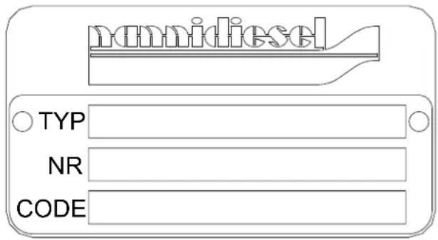
The TYP inscription indicates the commercial designation of the engine (eg. H4.150).
The NR inscription indicates the engine serial number.
The CODE inscription lists the various specifications of your engine.
Additional equipment
Your engine can be fitted with optional pieces of equipment (alternators, intercalated generator, hybrid propulsion, pumps, trolling valve, etc.)
Refer to the additional documentation concerning this equipment or contact your authorised Nanni Diesel dealer for more information.
Warranty
The owner of the engine is responsible for all safety and maintenance checks as well as for following the maintenance instructions as set forth in this manual and on the Silverwake warranty booklet. The performance and reliability of your engine depend on you following these instructions.
Maintenance should be entrusted to a specialist authorised by Nanni Diesel. The validity of the warranty is dependent on maintenance operations being carried out by an authorised representative.
Wear and tear on parts as well as maintenance costs arise from normal use of the engine and therefore do not constitute manufacturing or material faults under the terms of the warranty.
We strongly advise against making any changes to the engine's settings, as well as any other technical modification (accessories, spare parts, hitched equipment etc.) not authorised by Nanni Diesel.
Any modification will cause the warranty to be cancelled as we cannot be held liable for work carried out beyond our control.
Environmental responsibility
Nanni Diesel designs its engines to have minimum environmental impact and a maximum service life. This objective, however, can only be achieved with your full cooperation. Our operating and maintenance instructions are to help you to protect your engine and adopt responsible behaviour vis-à-vis the environment.
Ensure you only use the fuels and oils recommended in this manual. Using another type of fuel or oil could cause major generator malfunctions: higher consumption, reduced engine service life, greater discharge of exhaust gases.
When draining the oil and changing the oil or fuel filter dispose of the waste in the appropriate container. These fluids cause major damage to flora and fauna if discharged into nature. Ask the pump attendant for an absorption kit in the event of accidental discharge of oil or fuel into the water.
The different fluids used to run the engine are a health hazard. Carefully read the instructions on the packaging of these products and always check that the ventilation in the storage compartment is adequate.
Preparations before starting:
When the engine has been installed on board and before removing the protective elements covering the different orifices, clean the exterior surface of the propulsion system.
For transportation reasons, some of our engines are delivered without their operating fluids. In all cases, you must:
- Check the levels and fill the engine oil if necessary.
- Fill the exchanger with coolant and degas if necessary.
- Check the belt tension.
- Check the tightness of the different connections and drain caps (coolant and oil).
- Check the tightness of the alternator electrical lugs (check the cabling by referring to the corresponding documentation), battery terminals, circuit breaker, connection of extension sections, battery electrolyte level.
- Make a final check of the fixing elements and a visual check of the engine as a whole.
- Check the operation of the ventilation system.
Some of these operations are explained in more detail later in this manual.
Attention! : The modern diesel engine is precision equipment that requires the use of a high-quality fuel and lubricant.
Fuel supply
Ensure that the fuel contains no residues. If it does, use special filters.
Avoid using fuel mixed with water or other substances as you may damage the engine.
The engine performance is influenced by the fuel temperature, the temperature and relative humidity of the exhaust air and by the altitude.
Behaviour of the boat
The weight distribution on board can modify the centre of gravity of the boat and have an impact on its behaviour in navigation.
The condition of the hull is also a critical factor. A dirty and / or damaged hull will modify the behaviour of the boat.
The propeller must be adapted to the boat and the use that is made of it. A faulty operation of the boat is often due to an inadequate and / or damaged propeller.
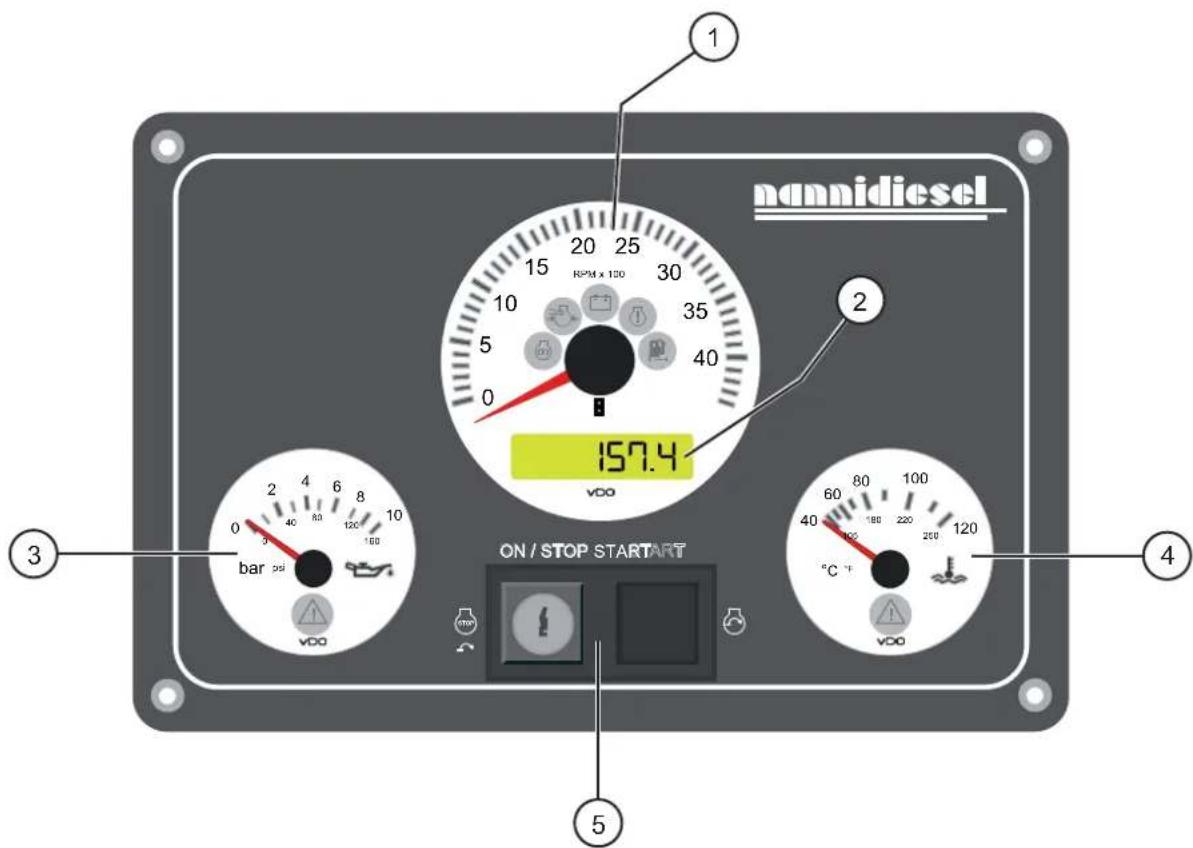
Instrument panel
The instrument panel provides you with important information about the engine when it is operational. Check this information regularly when the engine is operational. The position or appearance of the instruments represented here may vary depending on the type of instrument panel. Not all instrument panels have all these elements.
If your instrument panel does not match the models described in this chapter, contact your Nanni Diesel authorised dealer.
-
Revolution counter. Indicates the rotation speed of the engine in rpm. When the ignition is on, indicates the voltage at the battery terminals.
-
Hour meter/Voltmeter. Record the functioning hours of the engine. When the ignition is on, indicates the voltage at the battery terminals.
-
Engine oil pressure. Attention! This indicator does not show the engine oil level. This indicator shows the oil pressure. The pilot lamp inside the dial is lit and an audible alarm sounds if the oil pressure in the lubrication circuit falls. At idle, the pressure is generally lower.
Danger! : If this alarm goes off, stop the engine - except in cases of extreme urgency - and contact an authorised Nanni Diesel dealer.
- Coolant temperature. Indicates the coolant temperature. The pilot lamp inside the dial is lit and an audible alarm sounds if the coolant in the cooling circuit overheats.
In normal operation, the temperature must be between 75 and 85^ Celsius.
Danger! : If this alarm goes off, let the engine run at idle few minutes and check that the seawater flows through the exhaust outlet. If the water does not flow or if the temperature does not drop, stop the engine - except in cases of extreme urgency - and contact an authorised Nanni Diesel dealer.
- Starting switch/ key This component starts and stops the engine. The ON/STOP key switch powers up and stops the engine. The START button starts it.
Certain panels ("button" panels) may not be equipped with a starter key. The ON/STOP button switches on the engine.
Warning lights & alarms
- Heating. This indicator is lit when the glow plugs are heating the combustion chambers (if fitted on your engine).
- Battery charge. This indicator is lit when the engine is switched on (ignition). If it lights when the engine is running, this indicates an engine alternator charging fault.
- Water in fuel filter (if fitted). This indicator is lit when there is too much water in the fuel filter.
- Faulty system. This indicator is lit when there is a failure on the electronic system of the engine. If this indicator lights, contact an authorised Nanni Diesel dealer.
- High pressure turbo. This alert indicator indicates that the air pressure in the turbocharger is too high.
If one or more of these lights come on when the engine is running, stop the engine (except in emergencies) and contact an authorized dealer.
Throttle lever
On the majority of boats, the engine throttle includes the speed control and gear changing functions (forward / reverse).
However, some boats may be fitted with a reverse command or a safety mechanism that prevents the engine from being started if the throttle is not in the neutral position.
Get information from the boat builder about the type of throttle operation.
Auxiliary 12V output on instruments panel
The A4, B4 and C4 panels are equipped with an auxiliary output of 12V / 3A.
The interfaces linking the panels to the engine are fitted with a fuse.


Principal parts of the engine
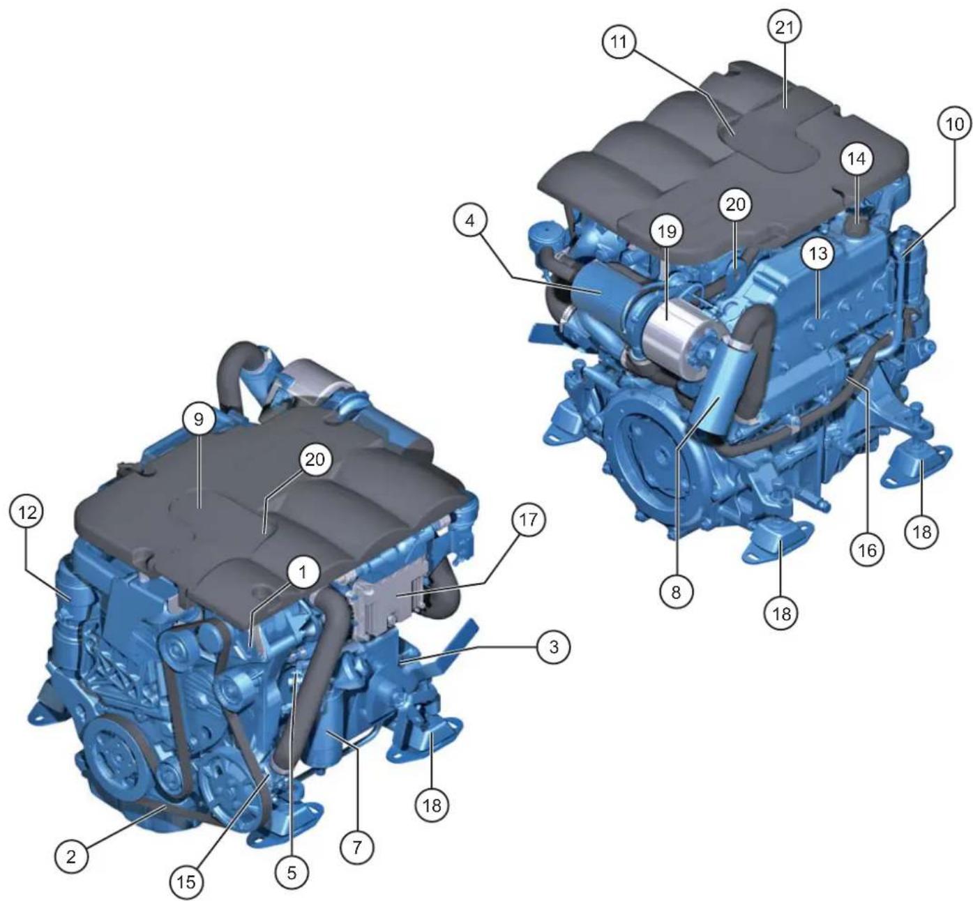
Certain equipment may not be part of your engine.
- Engine alternator
- Engine alternator belt
- Starter
- Air filter
- High pressure injection fuel pump
- Throttle lever
- Fuel filter
- Exhaust elbow
- Fuel fill orifice
- Oil drain orifice
-
Oil gauge
-
Oil filter
- Heat exchanger
- Coolant fill orifice
- Seawater pump
- Heat exchanger drain plug
- Electronic control unit
- Supports
- Turbocompressor
- Hoisting eyes
- Fuses
Installation inspection
Attention! : Your engine must be installed by an authorised shipyard or a qualified Nanni Industries representative in accordance with the on board assembly instructions. However, you can check some important points on the installation of the engine.
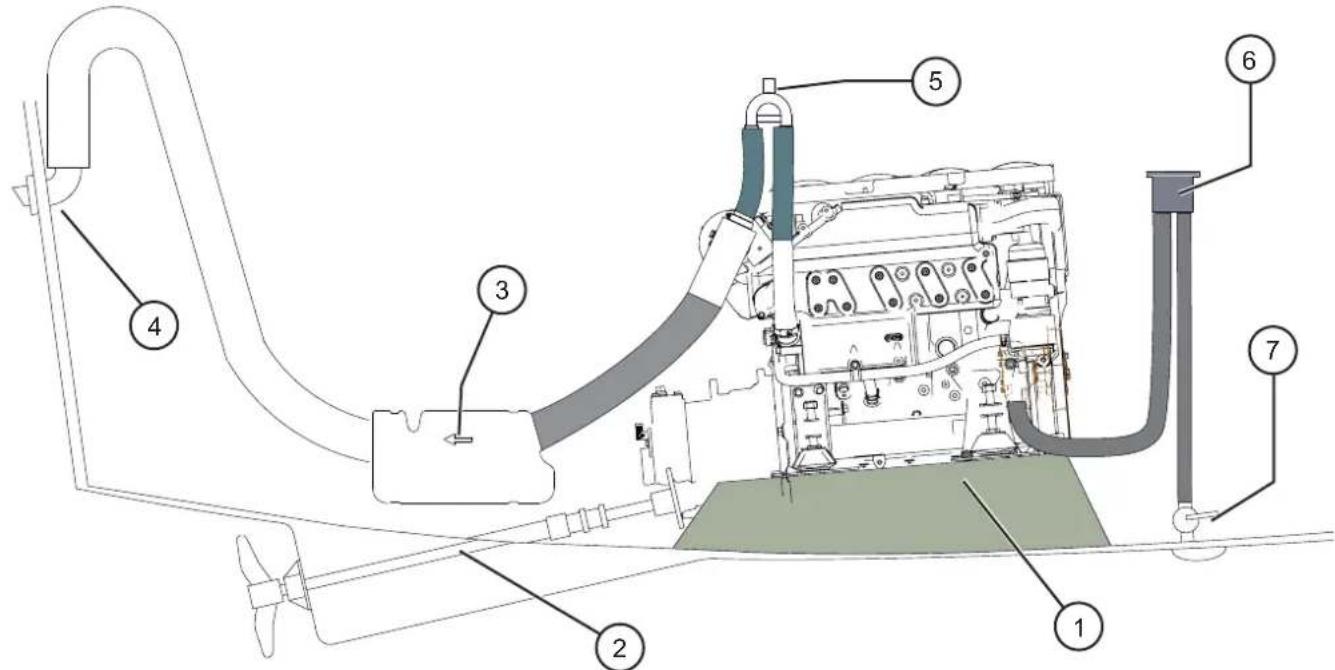
1. Engine frame
The engine frame must be solid and able to absorb all the dynamic stress as well as the weight of the engine. It must be connected to the hull by an area as large as possible.
The engine must not be at an angle of more than 15^ when the boat is stopped.
2. Propeller shaft
The choice of propulsion system must be made according to the restrictions arising from the engine, the boat, and the use of the boat.
3. Waterlock exhaust box
The waterlock must be positioned as close to the engine and as low as possible.
4. Hull outlet
The hull outlet must be located 15cm below the water line. The tube between the exhaust box and the hull outlet must form a swan-neck shape to avoid any water getting into the exhaust system through the hull outlet.
5. Anti-siphon valve
Mandatory on boats whose engine is below the waterline. The anti-siphon valve must be installed at the end of the seawater system before injection in the exhaust elbow and must be positioned above the waterline, between 0.5 and 2 metres.
6. Seawater filter
This must always be positioned at least 15cm above the waterline.
7. Through-hull valve
On yachts and boats that do not go above 12 knots, the water inlet must be turned towards the end of the boat.
On motor boats that go over 12 knots, the water inlet must be turned forwards the end of the boat.
Engine room
The temperature inside the engine compartment must not exceed 50^ with a maximum difference of 20^ with the outside temperature.
Slow boats must have a ventilator fitted. Fresh air from the front is circulated from front to back. The front air intake is located low down at the front of the engine compartment and the outlet high at the back for optimum air circulation.
Electrical installation
An incorrect or faulty electrical installation can cause leakage currents that can affect the galvanic protection of the engine and damage the engine subsequently.
The installer must ensure to take all necessary precautions to protect the engine against corrosion.
Operation of the engine
Before starting
Attention! : Before starting, ensure that the seawater intake is open as the seawater pump rotor can be damaged if run dry for just a few seconds.
Never use a starting aerosol or any other equivalent product. These products are highly flammable.
Before turning the starter key and before the engine is used each time:
- Open the hold space panel(s) to fully ventilate the hold space if it is not equipped with a fan. Otherwise run the fan in the hold space for 5 minutes.
- Check the fuel level.
- Check that the throttle is in the correct neutral position.
- Open the fuel supply valve and prime the system necessary
- Open the seawater intake valve (if fitted)
- Check there are no fuel, oil or coolant leaks
- Check the engine oil level and fill with the recommended oil if necessary. See the "Maintenance" section for more information.
- Check the coolant level and fill with the recommended coolant if necessary. See the "Maintenance" section for more information.
Attention! : Ensure you have refitted the protection elements before starting the engine.
- Close the battery switch (ON position)
Remark: If your engine has not been used for several months of if the fuel circuit has been drained, use the priming pump situated above the fuel filter. This fills the fuel circuit if it has drained out or after a circuit component has been replaced.
Danger! : The propeller can cause serious injury when it is moving, ensure that no-one is near the propeller before starting the engine and never sail near swimmers.
Starting the engine
Remark: When starting the engine for the first time, let it run at idle for several minutes.
If the engine is not used regularly, turn the ignition and let the engine run at idle until it reaches operating temperature. Do this at least one time per month when not in use.
Carry out the following operations to start your engine in complete safety:
- Put the throttle in the neutral position
- Put the key into the ON/STOP starting/switch
- Turn the key a quarter-turn to the right. All of the indicators will light and an audible signal will sound. This stage allows you to check that these elements are working properly. After a few seconds, only the oil and battery if charge indicators will remain lit.
- Depress the START button to the midpoint to begin heating and keep it depressed for 5 to 20 seconds depending on the ambient temperature. Depress the button fully to start the engine.
Button panel
For button panels (with no starter key):
- Press the ON/STOP button. All of the indicators will light and an audible signal will sound. This stage allows you to check that these elements are working properly. After a few moments, only the oil and battery charge indicators will remain lit.
- Depress the START button to the midpoint to begin heating and keep it depressed for 5 to 20 seconds depending on the ambient temperature. Depress the button fully to start the engine.
Attention! : Never press the START button when the engine is running.
Remark : Consult your authorised Nanni Diesel dealer about the precautions to take when using the engine in a cold environment.
Attention! : If the engine does not start on the first attempt, repeat the manoeuvre, waiting 5 to 15 seconds between each attempt, with the engine switched off. Never force it as there is a risk of water backflow into the engine via the exhaust system.
Let the engine warm up at idle few minutes before reaching your cruising speed.
During operation
RPM speed of the engine
Refer to the chapter «Technical specifications» for informations about the rated rpm speed of your engine.
Do not operate the engine at a too low rpm speed for a long period as it could lead to increased oil consumption among other things. At a low speed, the fuel combustion is not complete and deposits may form in the engine and in its exhaust system. Run the engine at full throttle for 4 to 5 hours per year in order to burn off any possible deposits.
Cruising speed d
Set your cruising speed to 200 rpm below the maximum speed at full throttle for the best sailing conditions.
Forward / reverse speed
Danger! : Never reverse the gear when the boat is at full speed. Gear changes made at too high speed can damage the engine and the transmission.
Carry out the following operations for forward / reverse manoeuvres:
- Lower the engine down to idling and wait for the boat to lose as much speed as possible.
- Bring the throttle to the neutral position and wait a few seconds.
- Push the control lever to the reverse direction change gear.
Running in
Operate your engine with care for the first 50 hours of operation.
Do not accelerate immediately after starting the engine without giving the engine the time to warm up by idling for several minutes and only run at full speed for short periods of time.
Stopping the engine
Let the engine run at idle in the neutral position for few minutes before turning it off, particularly if the engine has been running at high speeds and high throttle settings.
Turn the key counter-clockwise. The engine stops and all the indicators will be extinguished.
For button panels, depress the ON/STOP button and then release it.
Emergency stop
You can stop the engine manually if the standard shutdown procedure is not working or in an emergency by cutting the fuel supply.
Danger! : Working on a running motor is extremely dangerous.
After the engine has stopped
Open the circuit breaker (battery supply off), close the seawater intake valve (if fitted) and the fuel feed valve. Check the condition of the compartment in order to identify any leaks.
Danger! : Even after your engine has stopped, elements remain hot and pressurised for several minutes. As far as possible, limit work on the engine immediately after stopping it.
Attention: If the craft is being towed, stop the engine and always close the seawater intake valve to prevent the engine from accidentally fi lling with seawater.
TWIN-ENGINE BOATS: If sailing with a single engine, close the seawater intake valve of the stopped engine. Do not forget to open it again before restarting the engine.
Maintenance
The regular maintenance of your engine is essential for ensuring optimal reliability and service life. The following operations and the those described in the Silverwake warranty booklet will enable you to extend the service life of your engine and reduce its impact on the environment.
During the warranty period, it is essential that all work carried out by a Nanni Diesel authorised dealer. However, some regular checks, particularly those made each time the engine is used, can only be made by the owner.
Certain operations are explained to you further on so that you can work on the engine in an emergency or if there is no repair centre nearby. We recommend you have your work checked by a Nanni Diesel authorised specialist.
Attention! : As far as possible, limit work on the engine when it is running and/or when you are sailing.
These instructions only describe a part of the maintenance operations to be carried out. Find the complete list on the Silverwake warranty booklet. The operations listed on the Silverwake must be carried out by an authorised Nanni Diesel technician.
The instrument panel shows you how long your engine has run since its commissioning.
Remark: Certain equipment is optional and may not be part of your engine.
In order to preserve the mechanical qualities of the engine and prolong its service life, we recommend you follow the instructions below:
Use a coolant made of 50% water and 50% antifreeze. Use tap water for the mix: Water that is too hard will produce limescale build-up and will reduce the cooling system's effectiveness. This could lead to a piston jamming.
If you do not use antifreeze and the outdoor temperature is below zero degrees Celsius, make sure to empty the cooling water after every use.
The closed cooling circuit must be protected against corrosion. If this circuit malfunctions, this could reduce its efficiency and the engine's service life.
Do not run the starter for more than 15 seconds: The continuous use of the starter for more than 15 seconds will damage the system.
Choose a diesel fuel meeting standard DIN-EN 590. If using Biodiesel (according to UNI EN14214 specifications) this can be blended up to 5% with a fuel available in Europe (according to the DIN EN 590 standard: a lower quality fuel will result in poor combustion, which may cause starting problems and heavy smoke emissions.
Draining the fuel tank: Remove the deposits in the fuel regularly.
Use a good-quality lubricant: Poor-quality lubricating oil will damage the engine in terms of the wear of the parts, jamming, etc., or rather reduce its service life.
The recommended lubricant must have the following properties:
Degree: SAE 10W - 40
Minimum specifications ACEA A3, B3 or API SL, CF
Daily checks
Habitually and regularly check the condition of the engine and its compartment before and after it is used: check for the presence or not of fuel or oil leaks, the tightness of the different clamps and bolts, the condition of the belts, hoses and the various electrical cables, the wear of the zinc anode (if fitted), the battery electrolyte level.
These relatively simple checks can help you to detect possible faults before major work on your engine is required.
Attention! : Do not let oil, fuel or grease deposits build up around the engine as they may increase the risk of fire in the engine compartment.
Check the operation of the different lamps and indicators situated on the instrument panel.
Stuffing box
Regularly check the watertightness of your stuffing box (if equipped). As this system is not absolutely tight, it is natural that a slight amount of water passes through the stuffing box. Correct operation is characterized by a drop-by-drop water intake. If too much water comes in, contact your Nanni Diesel dealer.
Control cables
Inspect the cables and check that they are not shredded or loose. Grease the connections.
Fuel system
Danger! : Total cleanliness must be guaranteed when working on the fuel circuit. No impurities must enter the injection pump and the injectors. Carry out each of these operations with the engine cold and stopped.
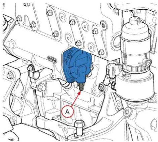
Bleeding the fuel circuit
The fuel circuit is self-priming but manual bleeding is required after replacing the fi liter, after having runnng out of fuel or after a work on the circuit if it has been emptied.
- Untighten the drain valve screw A on the engine fuel filter support.
- Pump the priming pump by pressing the button B repeatedly until bubble-free fuel comes out of the drain valve screw.
- Tighten the drain valve screw and lock the hand pump B.
Attention! : Avoid draining all the fuel in the filter when bleeding. If you have, remove the filter and replenish with fuel before replacing it and repeat the bleeding.
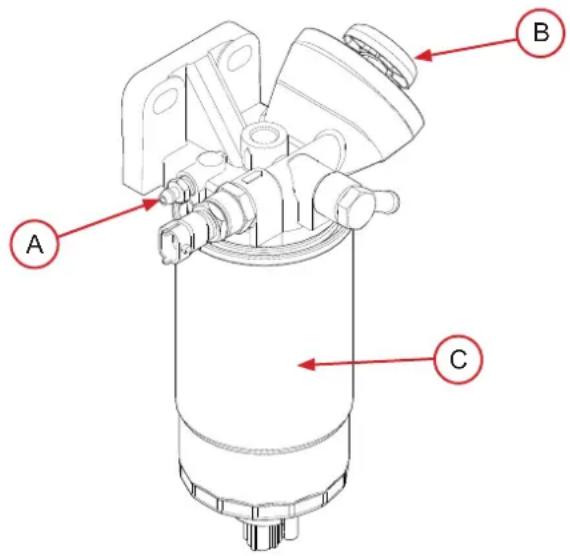
Replacing the fuel fi Iter
This fi tter treats the water and impurities in the fuel before it enters the injection circuit.
- Cut the fuel intake at the tank.
- Place a receptacle under the fi lter and then remove the used fi lter C cartridge.
- Apply a thin layer of fuel over the seal surface of the new fiiter cartridge before fitting it.
- Tighten it by hand until the fi liter makes contact with the fi liter head then tighten it by a half-turn.
- Untighten the drain valve screw to release the air. Open the fuel valve again and drain the circuit.
- Start the engine and check the assembly is leak-tight.
Attention! : Used filters must be disposed of in an appropriate container.
Fuel system
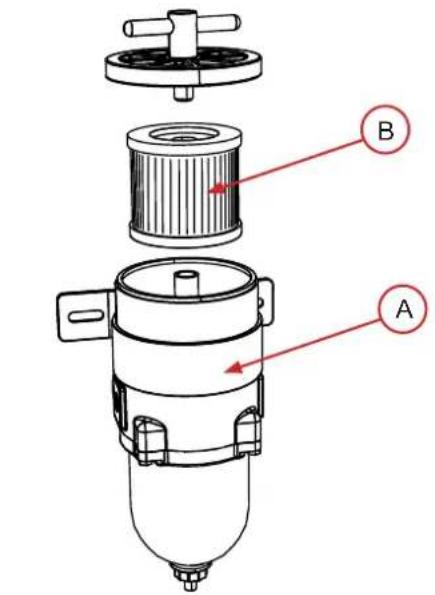
Replacing the fuel prefllter
The fuel prefilter is an optional component that purifies the diesel before it is injected in the engine. These instructions are given as an example only.
- Close the fuel valve on the fuel tank.
- Place a pail under the fuel prefilter. Remove the filter tank A
- Drain and clean the fi Iter tank.
- Replace the cartridge B and re-install the tank.
- Open the fuel valve. Drain the feed system then start the engine to check the leak-tightness.
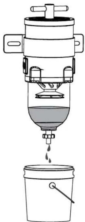
Draining the water from the fuel prefiter
Before starting the engine each time, ensure there is no water in the fuel prefi liter. If there is water, place a tray under the fuel prefi liter and then drain the water and impurities using the bottom cap/valve.
Lubrication circuit
Checking the oil level
Attention! : Carry out these operations with the engine stopped. Hot oil and hot surfaces can burn.
If oil of a different brand or viscosity to the previous oil is used, drain the old oil. Never mix two different types of oil. Observe the recommended draining intervals.
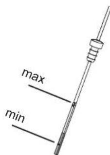
The oil level should be within the range indicated on the oil gauge. To check the oil level:
- Start the engine and let it run at idle for several minutes.
- Stop the engine and remove the starter key.
- Remove and wipe down the gauge rod.
- Re-insert it and then remove it.
- Check whether the oil level is between the two notches. If the level is too low, add more oil until reaching the specified level.
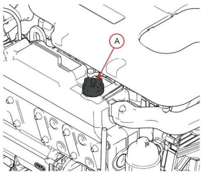
Fill the oil via the fill orifice situated on the top of the engine. Add the oil slowly and wait several minutes before checking the level again. This allows the oil to run into the engine crankcase.
Attention!: Do not fill the crankcase above the maximum level indicated on the gauge.

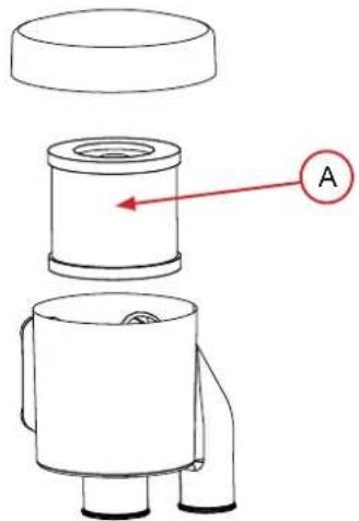
Replacing the oil fi Iter cartridge
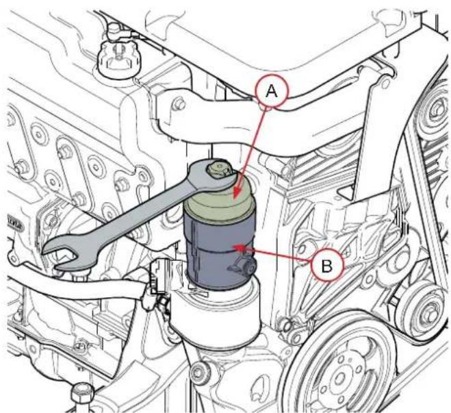
- Place a pail under the fi liter.
- Remove the oil filter cover A with a key.
- Remove the oil filter cartridge inside its casing B.
- Clean the filter support in order to prevent impurities from entering the engine.
- Apply a fine layer of oil over the rubber seal of the new cartridge.
- Remove the fi lter cartridge
- Install new cartridge, tighten it with a torque of 25Nm .
- After replacing the fi filter, check that the engine oil is not leaking through the seal and check the oil level using the gauge. Add oil if necessary.
Lubrication circuit
Draining the engine oil
Attention! : Carry out these operations with the engine stopped. Hot oil and hot surfaces can burn.
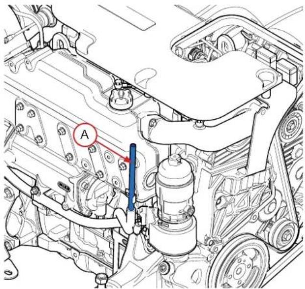
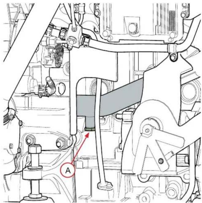
The oil is drained via the drain orifice using the drain pump, with the oil slightly warm.
- Start the engine and let it warm up for approximately 5 minutes so that oil suction is easier.
- Stop the engine. Remove the plug of the drain orifice A.
- Connect the drain pump to the orifice A. Use a pail to collect the extracted oil.
- Pump until the oil has been completely extracted. Refi II with the new oil (the amount of oil to add is indicated in the technical specifications section).
- Check the level with the gauge, ensuring you do not go above the maximum level.
- Start the engine and check that the oil pressure indicator is extinguished and that there are no leaks in the lubrication circuit. Let the engine warm up for several minutes and then check the oil level again. Fill again if necessary.
- Refit the cap of the drain orifice
Cooling circuit - coolant
The cooling system enables the engine to operate at an optimal temperature and protects it against frost and corrosion. The cooling system must be filled with a coolant comprising 50% water and 50% anti-freeze and anti-corrosion additive.
The coolant must be changed regularly as the additives become less effective over time. Prepare the mix before filling the exchanger.
If the engine must be switched off for a long period in an environment with a high risk of frost, the coolant must be drained.
Attention! : Never use just water to fill the cooling circuit. Always use a clean receptacle and ensure the fluids are well mixed.
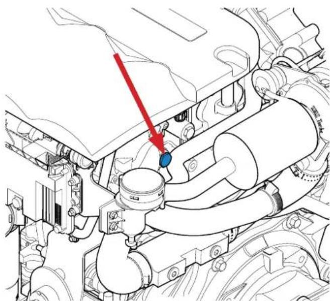
Coolant flling
Attention! : Do not check the coolant level when the engine is hot. Pressurised coolant can spurt and cause serious burns. Carry out this work with the engine stopped and cold. Only use new coolant when replenishing or adding coolant.
Regularly check the coolant level.
- Turn the fill cap A situated on the heat exchanger to its first stop to release the system pressure and then remove the cap.
- Check the coolant level: it must be between 1 and 2cm below the edge of the exchanger.
- Top up if necessary. Fill the heat exchanger slowly with coolant up to the maximum level in order to let the air escape.
- Run the engine for few minutes and keep it idling. Stop the engine, wait a few moments, then check the coolant level again. Fill again if necessary.
Cooling circuit - coolant
Draining the cooling circuit
The coolant in the cooling circuit must be drained in order to remove the various deposits that can build up in the circuit.
- Start the engine and let it run at idle for few minutes.
- Stop the engine, remove the key from the instrument panel, and let the engine cool to avoid burns.
- Place a pail under the drain cap A and untighten it.
- Let the coolant run out until the exchanger is empty.
- Clean the inside of the heat exchanger by following the instructions below before closing the cap.
Rinsing the cooling circuit
The cooling circuit must be rinsed after emptying.
- Remove the fill cap situated on the top of the heat exchanger and the drain cap.
- Clean the inside of the heat exchanger with clean water by placing a hose in the fi II cap.
- Continue until clean water runs from the drain orifice.
- Close the cap then refill with coolant.
Cooling circuit - seawater
Attention ! : When the craft is in the water, there is a risk of water penetrating the craft when working on the seawater circuit. Water can penetrate the craft via circuit components found below the waterline. Close the seawater intake valve (if fi tted) or prevent water discharge before working on this circuit!
Cleaning the seawater circuit is essential to preventing the formation of deposits and salt crystals. The presence of a seawater filter between the pump and the water intake is mandatory. Check and clean the filter regularly.
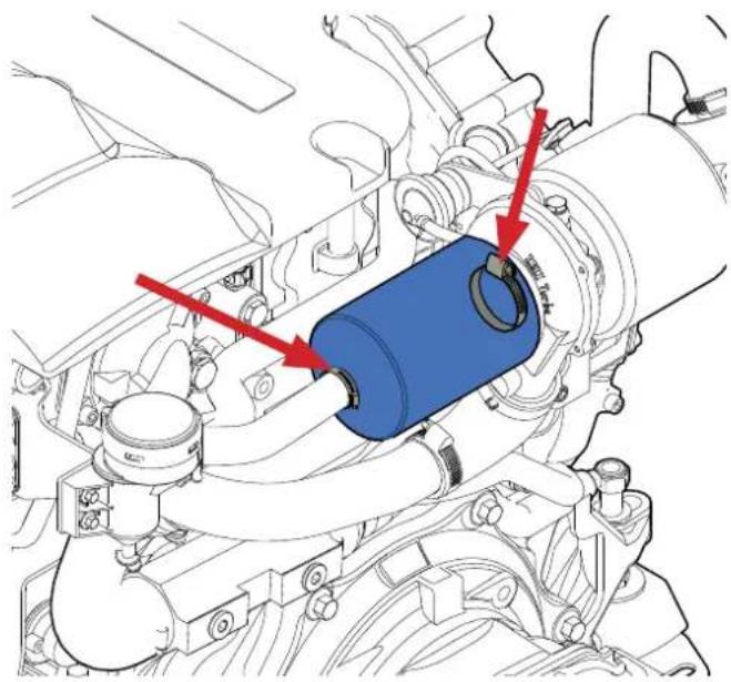
Cleaning the seawater fi Iter
The seawater filter is an optional component. These instructions are given as an example only.
- Check the condition of the seawater filter with the engine stopped. If deposits have formed, remove the filter in order to clean it.
- Remove the cover and then the filtering part A. Remove all the debris on the housing.
- Rinse the filter and the housing with fresh water and check the condition of the seal, then re-install all the components and check there are no water and/or air leaks in the circuit when operational.
Draining the seawater circuit
- Close the seawater intake valve.
- Place a pail under the drain cap A
- Remove the cap A
- Let the water flow in the pail
- Refi t the cap
- Drain also the exhaust circuit. A small amount of water may remain in the bottom of the Waterlock box.
Cooling circuit - seawater
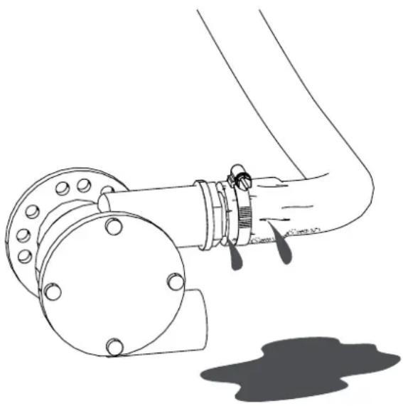
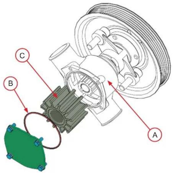
Replacing the seawater pump rotor
The seawater pump rotor is an essential component. It must be replaced regularly along with the seal. A worn rotor could crack and damage the cooling system. Always have a replacement rotor on board the craft.
- Close the seawater intake valve.
- Remove the seawater pump cap A and the seal B, then remove the rotor C without damaging it.
- Check the condition of the rotor: replace it if even the most minor defect is noted.
- Clean the elements retained.
- Fit a new rotor by turning it clockwise.
- Lubricate the pump casing and the inside of the lid with waterproof grease for rubber.
- Refi t the water pump cap using a new seal.
- Open the seawater intake valve and then start the engine to check that the circuit is leak-tight.
Air fi I ter
Attention! : Carry out these operations when the engine is stopped and cold.
The air filter essentially reduces the level of noise made by the engine and purifi es the air injected into the combustion chamber.
If the fi lter is too clogged, replace it. If it is not:
- Remove the hose retaining ring and remove the fi liter.
- First clean the filter with compressed air and then rinse it with clean water.
- Let it dry completely at ambient temperature and then replace it.
Engine electrical system
Attention! : Stop the engine and the cut the battery supply before working on the electrical circuit.
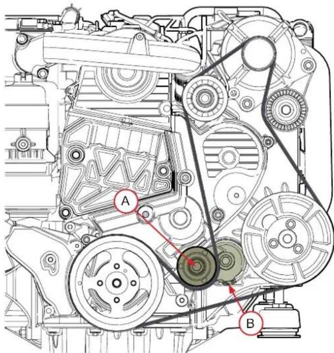
Alternator belt
Make this check after running the engine when the belt is slightly hot.
Attention! : Some parts of the engine can be extremely hot.
To replace the belt, act on the tensioner A until the holes B are aligned then use a locking pin to lock it. You can then take off and replace the belt.
After replacing it, move the tensioner A to release the locking pin and remove it in order to tighten the belt. Then release the tension on the automatic tensioner A which will then apply the correct tension on the belt.
Check the electrolyte level.
The starter battery must remain clean and dry. Oxidation or the deposit of impurities on the battery and on its terminals may lead to short circuits, voltage drops and premature discharging, notably in wet weather.
The battery terminals and the cables must be cleaned with a brass brush in order to remove any oxidation. Tighten the cable terminals and lubricate them with appropriate grease.
If the battery is replaced, use a battery with similar specifications to the previous one.
If starting with an emergency battery and connection cables, proceed as follows:
- Connect the emergency battery to the main battery by connecting the + to the + and the - to the -. When the engine has started, remove the connection cables.
You should disconnect the 2 battery cables when:
-
You use a battery charger
-
Before carrying out any work on the electrical equipment
-
Before carrying out any welding work
Changing fuses
The protective fuses in the electrical system are disposable. These blown in the event of a voltage surge or a short-circuit in order to prevent any damage to the parts. In the event some anomaly has caused a fuse to blown, find the cause before changing the fuse. Always use a fuse with the properties as the one being replaced
Protection against corrosion - Zinc anode
When at least two different kinds of metal are immersed in seawater, polluted water or water with a high mineral content, a chemical reaction occurs and an electrical current is established between the metals.
This electrical current leads to the metal that is more active from a chemical point of view, or more anodic metal being eroded. If this is not controlled, this galvanic erosion can seriously damage the parts and propulsion system that are exposed to water.
In order to protect the engine and the seawater cooling system from corrosion, the engine is fitted with two sacrificial anodes located on the end cover of the exchanger.
To remove the anode
- Let the engine cool down
- Close the seawater intake valve
- Drain the seawater system
- Remove the set formed by a cap, a seam and the anode.
Remark: Remove the deposits from the surface of the anode using glass paper before determining the level of erosion. Do not use a soft steel brush as this could leave deposits that are likely to speed up corrosion.
If more than 50% of the anode has been used up, replace both it and the seal.
Attention! : Screw the anode cap back on tightly and do not forget to re-open the seawater intake valve.
Protecting the engine during periods of inactivity
A set of operations will protect the engine during long periods of non-use. We recommend that you have these winterization operations carried out by a Nanni Diesel authorised workshop.
During short periods of inactivity, carry out the following operations:
- Check all the electrical contacts and protect them with an anti-oxidant spray if necessary.
- Check the electrolyte level and that the battery is charged.
- Take the engine to its operating temperature (70 - 80^) at least once a month.
For long periods of inactivity, carry out the operations below. This treatment is effective for 6 months. If the period of inactivity is extended, repeat this treatment.
- Drain the engine and gearbox oil, change the oil fiiter and fi II with new oil. Drain and replace the coolant.
- Drain the fuel prefilter and replace the cartridge (if equipped).
- Change the fuel filter and drain the fuel circuit with storage fuel.
- Inspect the air filter. Change it if necessary.
- Check that the injection pump rack moves freely (if equipped).
- Inspect the control cables (make sure the engine is at idle and the gearbox in neutral).
- Remove all the mechanical parts and the ancillary applications that could be damaged during the no-load operation of the engine.
- Inspect the belts. Replace it if necessary.
- Start the engine and let it operate few minutes without load.
- Run the engine at 1500-1800 rpm for 15 minutes until the operating temperature (70 - 80^) is reached.
- Stop the engine and remove the start key from the panel.
- Let the engine cool down to avoid the risk of burns.
- Block all the openings (admission, exhaust, fuel line, air valve).
- Loosen belts.
- Remove and store the impeller of the sea water pump in a hermetic opaque container. Indicate clearly with a note on the engine «IMPELLER OF RAW WATER PUMP MISSING».
-
Remove the battery.
-
Spray an anti-damp spray on the engine and the electric parts (starter, alternator, wire harness connectors and panel).
- Clean the hold and Install a dehumidifi er.
- Grease the control cables (if equipped)
Restarting the engine
After a period of inactivity, carry out the following operations before restarting the engine:
- Check that the battery is charged and the level of the liquid. Check that the electrical contacts are intact and working correctly.
- Check the oil level. If necessary fill the oil tank or drain the oil according to the intervals given in the Silverwake booklet.
- Replace the oil filter
- Check the coolant level. Fill with coolant if necessary or drain the coolant according to the intervals given in the Silverwake booklet.
- Replace the fuel filter according to the intervals given in the Silverwake booklet.
- Replace the air fiiter according to the intervals given in the Silverwake booklet.
- Re-tighten the belt.
- Check the tightness of the connections.
- Check the integrity of the impeller of the seawater pump and put it back into the pump.
- Remove the exterior protection treatment and all the covers.
- Start the engine and if no defaults appear, let it run for few minutes without load.
- Stop the engine and check the engine oil and coolant levels. Check for leakage.
Prolonged storage
For prolonged storage before or after being used for the first time, a specific set of measures should be adopted. Contact your Nanni Diesel authorised engineer.
Fault-finding
This section helps you to understand the different problems that may arise on your engine. The safest way to correct the problems you may encounter, however, is to contact a qualified Nanni Diesel dealer. Some operations must be carried out by a qualified Nanni Diesel authorised dealer. These operations are marked in bold in the tables below.
This non-exhaustive list serves as a tool in emergencies and should never be considered a repair procedure. Some of the components listed may not be part of your engine.
| Faults and probable causes | |
| Engine does not start / starter does not turn | |
| Faults Solution | |
| Circuit breaker is open or fuse has blown | Check and re-install the circuit breaker or replace the fuse or replace the circuit breaker |
| Electrical circuit breaker is not working | |
| Battery switch is open (battery main switch) Close the switch | |
| Electrical connections are faulty | Check the electrical connections and wires (especially the battery cables) Clean and tighten the connections |
| Battery faulty Test and charge or replace the battery if faulty | |
| Starting procedure defective Read and implement the starting procedure | |
| Fuel tank empty or fuel valve closed Fill the tank or open the valve | |
| Fuel pump faulty Replace the pump | |
| Fuel fi liters clogged or water present | Clean or replace the fuel fi liters or drain the water from the prefi liter then drain the circuit |
| Fuel contaminated or too old | Drain the tank if contaminated and fill with clean fuel |
| Fuel pipe or air pipe of tank blocked or bent | Replace the bent pipes or blow in compressed air to remove the obstruction |
| Air present in fuel injection system Drain the injection system | |
| Engine overheats / Engine coolant temperature too high | |
| Faults Solution | |
| Seawater valve is closed Open the seawater valve | |
| Seawater filter is clogged | Close the seawater valve and clean the filter |
| Seawater pump is sucking air | Check the position and seal of the seawater fiiter cover and the suction hose |
| Coolant circuit pump belt is slack or faulty Re-tighten or replace the belt | |
| Coolant pump is faulty Replace the pumpe and the belt | |
| Seawater pump rotor is faulty Replace the rotor | |
| Insufficient coolant | Fill with coolant and check that the cooling system is leak-tight |
| Thermostat is malfunctioning Replace the thermostat | |
| Cooling system is blocked Locate the problem and clean | |
| Closed cooling circuit is dirty Clean and rinse | |
| Loss of pressure in the closed cooling circuit | Check there are no leaks. Clean, inspect and check the fi ll cap |
| Coolant is unsuitable | Use the recommended coolant (see technical specifi cations) |
Technical specifications
| ENGINE SPECIFICATIONS | H4.115 H4.130 H4.150 H4.170 | |||
| Cycle | 4 strokes Diesel | |||
| Max. power - kW (hp)* | 84.6 (115) 97 (130) 1 | 11 (150) 126 (170) | ||
| Number of cylinders / Arrangement | 4 in line | |||
| Displacement (cm³) | 1991 | |||
| Distribution | 4 valves per cylinder | |||
| Compression rate | 17.5 : 1 | |||
| Aspiration | Turbocompresseur et intercooler | |||
| Bore x stroke (mm) | 83 x 92 | |||
| Maximum rpm speed at full throttle (rpm)* | 3000 ± 50 tr/min | 4000 ± 50 tr/min | ||
| Idle rpm speed (rpm)* | 700 ± 50 tr/min | 700 ± 50 tr/min | ||
| No load rpm speed (rpm)* | 3120 ± 50 tr/min | 4120 ± 50 tr/min | ||
| Theoric fuel consumption (l/h) | 21.8 @ 3000 tr/min | 29.5 @ 4000 tr/min | 34.1 @ 4000 tr/min | 37.4 @ 4000 tr/min |
| Weight without gearbox (kg) | 250 | |||
| INJECTION SYSTEM | H4.115 H4.130 H4.150 H4.170 | |||
| Injection | Direct Common Rail | |||
| Injection order | 1-3-4-2 | |||
| Injection pump | BOSCH Common Rail (CRS 2.0) | |||
| Injection pressure (bar) | 1600 | |||
| LUBRICATION | H4.115 H4.130 H4.150 H4.170 | |||
| Type | Forced by pump | |||
| Pressure at idle rpm speed (bar) | 1 - 4 | |||
| Capacity (engine on an horizontal axis) | 3.2 mini - 4.2 maxi | |||
| COOLANT | H4.115 H4.130 H4.150 H4.170 | |||
| Pressure setting of the plug (bar) | 1.2 | |||
| Coolant capacity (50% water - 50% antifreeze) | 7.7 | |||
| ELECTRICAL | H4.115 H4.130 H4.150 H4.170 | |||
| Starter (kW) | 2 | |||
| Battery capacity (Ah) | 100-120 | |||
| Alternator (V/A) | 12V / 110A | |||
- At engine flywheel, as per ISO 8665-1
Certain specifications may vary depending on your order.
The recommended cruising speed is 200 rpm under the maximum rpm speed at full throttle
Nanni Industries S.A.S.
11, Avenue Mariott e - Zone Industrielle
BP 107-33260 La Teste France
Tel: +33 (0)5 56 22 30 60
Fax: +33 (0)5 56 22 30 79
E-mail: contact@nannidiesel.com
ISO 9001
BUREAU VERITAS
Certification

© 2009 - Nanni Industries S.A.S
The images, text and information contained in this document are based on the product specifications at the time this document was published. Nanni Diesel reserves the right to alter this document without notice.
Notice de conduite
H4.115
H4.130
H4.150
H4.170
Pour retiree I'anode
11, Avenue Mariott e - Zone Industrielle
BP 107-33260 La Teste France
Tel: +33 (0)5 56 22 30 60
Fax: +33 (0)5 56 22 30 79
E-mail: contact@nannidiesel.com
ISO 9001
BUREAU VERITAS
Certification

© 2009 - Nanni Industries SAS


- Marine Diesel engines
- Contents
- Safety precautions 3
- Presentation 6
- Instrument panel 8
- Principal parts of the engine 10
- Installation inspection 11
- Operation of the engine 12
- During operation 13
- Stopping the engine 13
- Maintenance 14
- Daily checks 15
- Fuel system 16
- Lubrication circuit 18
- Cooling circuit - coolant 20
- Cooling circuit - seawater 22
- Replacing the seawater pump rotor 23
- Air filter 24
- Engine electrical system. 25
- Protection against corrosion - Zinc anode 26
- Protecting the engine during periods of inactivity 27
- Fault-finding 28
- Technical specifications 30
- Safety precautions
- Exhaust gas
- Risk of electric shock
- Risk of burns
- Risk of fire
- Risk of explosion
- Accidental starting
- Risk of battery explosion
- Battery acid
- Rotating parts
- Lifting the engine
- Maintenance and spare parts
- Chemical products
- Thank you for choosing a Nanni Diesel engine!
- www.nannidiesel.com
- Identification plates
- Additional equipment
- Warranty
- Environmental responsibility
- Preparations before starting:
- Fuel supply
- Behaviour of the boat
- Instrument panel
- Warning lights & alarms
- Throttle lever
- Auxiliary 12V output on instruments panel
- Principal parts of the engine
- Certain equipment may not be part of your engine.
- Installation inspection
- Engine frame
- Propeller shaft
- Waterlock exhaust box
- Hull outlet
- Anti-siphon valve
- Seawater filter
- Through-hull valve
- Engine room
- Electrical installation
- Operation of the engine
- Before starting
- Starting the engine
- Button panel
- During operation
- RPM speed of the engine
- Cruising speed d
- Forward / reverse speed
- Running in
- Stopping the engine
- Emergency stop
- After the engine has stopped
- Maintenance
- Daily checks
- Stuffing box
- Control cables
- Fuel system
- Bleeding the fuel circuit
- Replacing the fuel fi Iter
- Lubrication circuit
- Checking the oil level
- Replacing the oil fi Iter cartridge
- Draining the engine oil
- Cooling circuit - coolant
- Coolant flling
- Draining the cooling circuit
- Rinsing the cooling circuit
- Cooling circuit - seawater
- Cleaning the seawater fi Iter
- Draining the seawater circuit
- Replacing the seawater pump rotor
- Air fi I ter
- Engine electrical system
- Alternator belt
- Check the electrolyte level.
- Changing fuses
- Protection against corrosion - Zinc anode
- To remove the anode
- Protecting the engine during periods of inactivity
- Restarting the engine
- Prolonged storage
- Fault-finding
- Technical specifications
- Nanni Industries S.A.S.
- © 2009 - Nanni Industries S.A.S
- Notice de conduite
- Pour retiree I'anode
- © 2009 - Nanni Industries SAS
Brand : Nanni
Model : H4.115
Category : Marine engine