
TD 740 TC ES BK - Cooker Ariston Thermo - Free user manual and instructions
Find the device manual for free TD 740 TC ES BK Ariston Thermo in PDF.
| Product Type | Built-in Gas Hob |
| Brand | Ariston Thermo |
| Model | TD 740 TC ES BK |
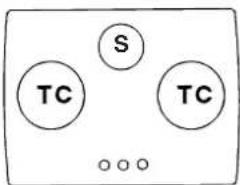
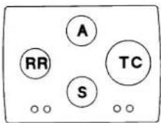
| Number of Burners | 4 (Rapid Reduced, Semi-rapid, Auxiliary, Triple Crown) |
| Nominal Power of Rapid Reduced (RR) Burner | 2.60 kW |
| Nominal Power of Semi-rapid (S) Burner | 1.65 kW |
| Nominal Power of Auxiliary (A) Burner | 1.00 kW |
| Nominal Power of Triple Crown (TC) Burner | 3.25 kW |
| Power Supply | Gas (adaptable Natural, Butane, Propane) and electric 220-240 V ~ 50/60 Hz |
| Built-in Niche Dimensions | 555 x 475 mm |
| Worktop Thickness | 20 to 40 mm |
| Minimum Distance from Hood | 650 mm (with hood), 700 mm (without hood) |
| Ignition | Electronic (spark) or manual (gas lighter) |
| Safety Device | Thermocouple (automatic gas shut-off in case of accidental flame extinction) |
| Surface Material | Glass (glass cooking surface) |
| Cleaning | Warm water and non-abrasive detergent; scraper for stubborn residues |
| Compatible Gas Types | Natural gas G20/G25, Liquid gas (Butane/Propane) |
| Injectors | Interchangeable to adapt to gas type (7 mm screw) |
| Gas Connection | G 1/2 male thread, rigid or flexible stainless steel pipe |
| Electrical Connection | Three-core cord with grounding (mandatory) |
| Appliance Class | Class 3 (built-in) |
| Usage | Domestic non-professional |
| Compliance | Directives 73/23/CEE, 89/336/CEE, 90/396/CEE, 93/68/CEE, 2002/96/EC |
| Spare Parts | Injectors, taps, gaskets; use approved original parts |
Frequently Asked Questions - TD 740 TC ES BK Ariston Thermo
User questions about TD 740 TC ES BK Ariston Thermo
0 question about this device. Answer the ones you know or ask your own.
Ask a new question about this device
Download the instructions for your Cooker in PDF format for free! Find your manual TD 740 TC ES BK - Ariston Thermo and take your electronic device back in hand. On this page are published all the documents necessary for the use of your device. TD 740 TC ES BK by Ariston Thermo.
USER MANUAL TD 740 TC ES BK Ariston Thermo
natural_image
Illustration of a hand using a paintbrush to brush residue in a circular container (no text or symbols)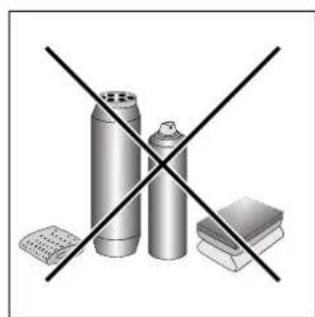
natural_image
Illustration of three metallic cylindrical objects crossed with a black 'X' line, next to a flat base (no text or symbols)Fig. A Fig. B
natural_image
Simple line drawing of a heating or cooling system with a stove, fan, and cooling unit (no text or symbols)
natural_image
Simple line drawing of a house interior with steam rising from the chimney to a stove (no text or symbols)natural_image
Diagram of a device casing with internal components and mounting holes (no text or symbols)natural_image
Pure mechanical assembly diagrams showing two cross-sectional views of a vehicle or bracket (no text or symbols)natural_image
Technical line drawing of a mechanical assembly with cross-sectional and top views (no text or symbols)natural_image
Two mechanical components with cylindrical pins and mounting base, shown from different angles (no text or symbols)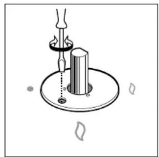
natural_image
Diagram of a mechanical device with a lever and base, showing no text or symbols
Congratulations on choosing an Ariston appliance, which you will find is dependable and easy to use. We recommend that you read this manual for best performance and to extend the life of your appliance. Thank you.
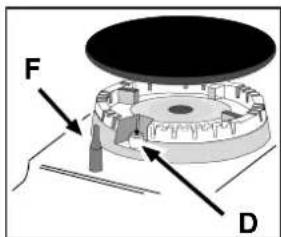
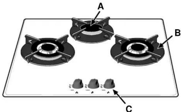
Close-up View
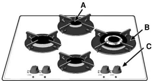
A. Gas Burners
B. Support Grid for Cookware
C. Control Knobs for Gas Burners
D. Ignitor for Gas Burners (only on certain models)
F. Safety Device (only on certain models) - Activates if the flame accidentally goes out (spills, drafts, etc.), interrupting the delivery of gas to the burner.
How To Use Your Appliance
The position of the corresponding gas burner is indicated on each control knob.
Gas Burners
The burners differ in size and power. Choose the most appropriate one for the diameter of the cookware being used.
The burner can be regulated with the corresponding control knob by using one of the following settings:
• Off
High Low
To turn on one of the burners, place a lighted match or lighter near the burner, press the knob all the way in and turn in the counter-clockwise direction to the "High" setting.
On those models fitted with a safety device (F), the knob must be pressed in for about 6 seconds until the device that keeps the flame lighted warms up.
On those models fitted with an ignitor (D), to light a burner, simply press the corresponding knob all the way in and then turn it in the counter-clockwise direction to the "High" setting, keeping it pressed in until the burner lights.
Caution: If the burner accidentally goes out, turn off the gas with the control knob and try to light it again after waiting at least 1 minute.
To turn off a burner, turn the knob in the clockwise direction until it stops (it should be on the “•” setting).
How to Keep Your Cooktop in Shape
Before cleaning or performing maintenance on your appliance, disconnect it from the electrical power supply. To extend the life of the cooktop, it is absolutely indispensable that it be cleaned carefully and thoroughly on a frequent basis, keeping in mind the following:
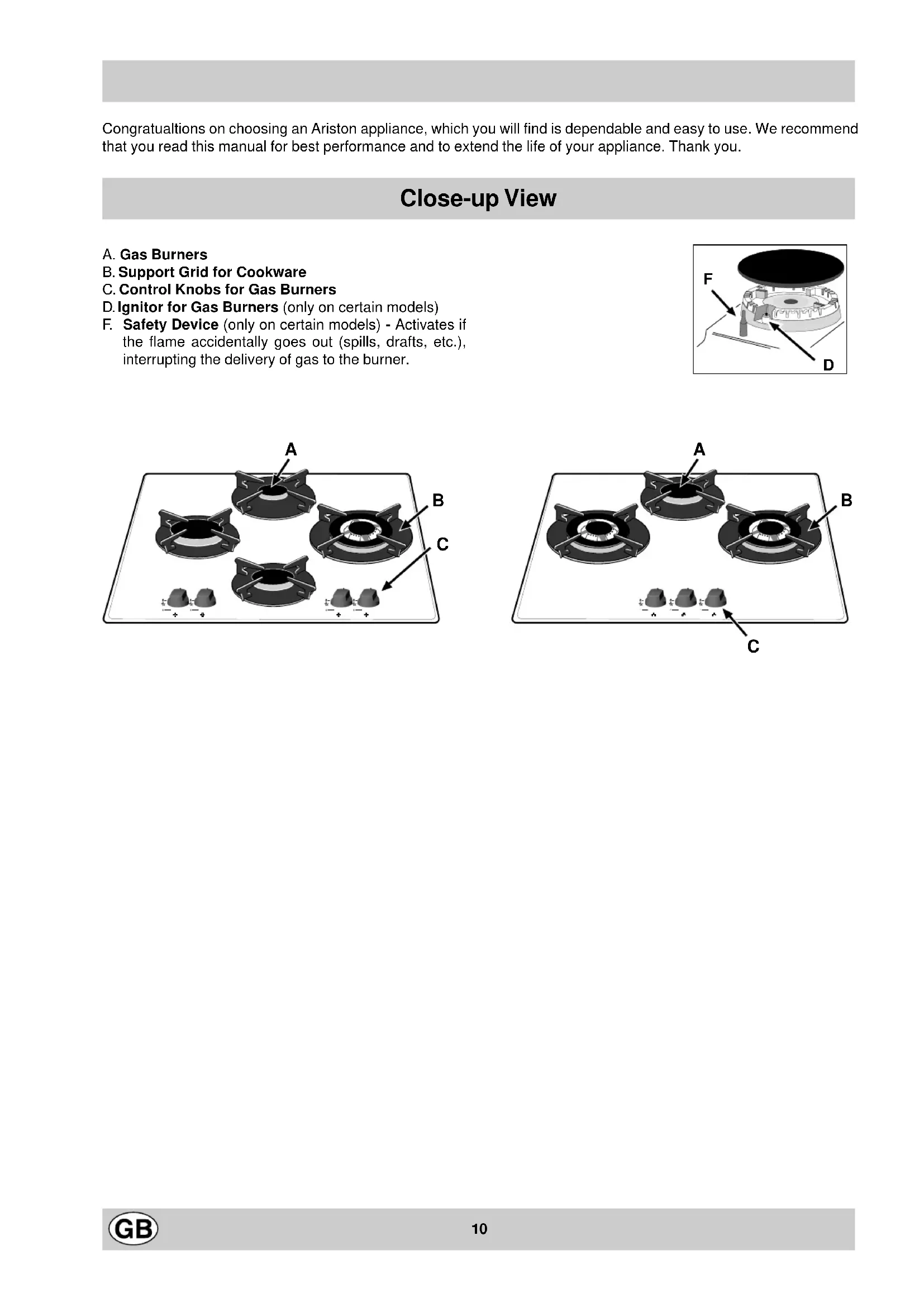
Do not use steam equipment to clean the appliance.
- Enameled and glass parts must be washed with lukewarm water without using abrasive powders or corrosive substances that could damage them;
- The removable parts of the burners should be washed frequently with warm water and soap, making sure to remove caked-on substances;
- On cooktops with automatic ignition, the end of the electronic ignition device must be cleaned carefully and frequently, making sure that the gas holes are not clogged;
- the top must be cleaned with glass cleaning products. Avoid using abrasive products and abrasive sponges that could scratch the glass.
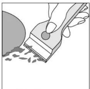
- the glass surface should be cleaned regularly with a solution of warm water and a non-abrasive detergent. First, remove all food buildup or grease with a cleaning scraper, e.g. (not supplied) (Fig. A).
Clean the cooking surface when it is still warm with a suitable cleaning product, then rub with a damp cloth and dry. Sugar or foods with a high sugar content that have melted onto the surface must be removed immediatley with a scraper while the cooking surface is still hot. Do not use abrasive sponges or cleaning products under any circumstances. This holds true for chemically aggressive cleaners, like oven sprays and stain removers (Fig. B);
natural_image
Illustration of a hand using a paintbrush to brush residue in a circular container (no text or symbols)Fig. A Fig. B

natural_image
Illustration of three spray cans crossed with a black X symbol (no text or labels)Greasing the Taps
The taps may jam in time or they may become difficult to turn. If so, the tap itself must be replaced.
N.B.: This operation must be performed by a technician authorised by the manufacturer.
Practical Advice
Practical Advise on Using the Burners
For best performance, follow these general guidelines:
- Use the appropriate cookware for each burner (see table) in order to prevent the flame from reaching the sides of the pot or pan;
- Alwasy use cookware with a flat bottom and keep the lid on;
- When the contents come to a boil, turn the knob to "Low".
| Burner ø Cookware Diameter (cm) | |
| Reduced Fast (RR) 22 - 24 | |
| Semi Fast (S) 16 - 20 | |
| Auxiliary (A) 10 - 14 | |
| Triple Crown (TC) 24 - 26 | |
To identify the type of burner, refer to the designs in the section entitled, "Burner and Nozzle Specifications".
Is there a problem?
It may occur that the cooktop does not function or does not function properly. Before calling customer service for assistance, lets see what can be done.
First of all, check to see that there are no interruptions in the gas and electrical supplies, and, in particular, that the gas valves for the mains are open.
The burner does not light or the flame is not uniform around the burner.
Check to make sure that:
• The gas holes on the burner are not clogged;
- All of the movable parts that make up the burner are mounted correctly;
- There are no draughts around the cooking surface.
The flame does not stay lighted on the model with the safety device.
Check to make sure that:
- You press the knob all the way in;
- You keep the knob pressed in long enough to activate the safety device.
- The gas holes are not clogged in the area corresponding to the safety device.
The burner does not remain on when set to "Low".
Check to make sure that:
• The gas holes are not clogged.
- There are no draughts near the cooking surface.
- The minimum has been adjusted correctly (see the section entitled, "Minimum Regulation").
The cookware is not stable.
Check to make sure that:
- The bottom of the cookware is perfectly flat.
- The cookware is centered correctly on the burner.
- The support grids have not been inverted.
If, despite all of these checks, the cooktop does not function properly and problem persists, call the nearest Merloni Elettrodomestici Customer Service Centre, informing them of:
- The type of problem.
- The abbreviation used to identify the model (Mod. ...) as indicated on the warranty.
Never call upon technicians not authorized by the manufacturer, and refuse to accept spare parts that are not original.
Safety Is a Good Habit to Get Into
To maintain the EFFICIENCY and SAFETY of this appliance, we recommend:
-
call only the Service Centers authorized by the manufacturer
• always use original Spare Parts -
This manual is for a class 3 built-in cooktop.
- This appliance is designed for non-professional use in the home and its features and technical characteristics must not be modified.
• These instructions are only valid for the countries the symbols for which appear on the manual and the serial plate. - The electrical system of this appliance is safe only when it is correctly connected to an adequate earthing system, as required by current safety standards.
Prevent children and the disabled from coming into contact or having access to the following, as they are possible sources of danger:
- The controls and the appliance in general;
- The packaging (plastic bags, polystyrene, nails, etc.);
- The appliance, during and immediately after use given the heat generated by its use;
- The appliance when no longer in installed (in this case, all potentially dangerous parts must be made safe).
The following should be avoided:
- Touching the appliance with wet parts of the body;
- Using the appliance with bare feet;
- Pulling on the appliance or the power supply cord to disconnect them from the electrical outlet;
- Improper and/or dangerous use;
- Obstructing the ventilation or heat dissipation slots;
- Allowing the power supply cord of small appliances to come into contact with the hot parts of the cooktop;
- Exposure to atmospheric agents (rain, sun);
- Using flammable liquids nearby;
- Using adaptors, multiple outlet plugs and/or extensions;
- Using unstable or deformed cookware;
- The top made is resistant to sudden temperature changes and shocks. However, if it is struck with pointed utensils or objects such as cutting knives, it may crack or break. If this occurs, disconnect the appliance immediately from the power supply and contact an authorised service centre.
- Trying to install or repair the appliance without the assistance of qualified personnel.
The assistance of qualified personnel must be called upon in the following cases:
- Installation (in accordance with the manufacturer's instructions);
- When in doubt about the operation of the appliance;
- Replacement of the electrical outlet because it is incompatible with the plug.
Contact service centers authorized by the manufacturer in the following cases:
- When in doubt about the condition of the appliance after having removed the packing;
- Damage to or replacement of the power supply cord;
- In the case of a breakdown or malfunction: ask for original spare parts.
It is recommended that you follow the guidelines below:
- Only use the appliance to cook food, avoiding all other uses;
- Check the condition of the appliance after it has been unpacked;
- Disconnect the appliance from the power supply in the event of malfunction and always before cleaning or maintenance;
- When not in use, disconnect the appliance from the power supply and turn off the gas valve (if present);
- Always check to make sure that the control knobs are on the “•”/“o” setting when the appliance is not in use;
- Cut the power supply cord after disconnecting it from the electrical mains when you decide to no longer use the appliance.
- The manufacturer will not be held liable for any damages arising out of : incorrect installation or improper, incorrect or unreasonable use..
Installation Instructions for built-in
The following instructions are intended for the installer so that the installation and maintenance procedures may be followed in the most professional and expert manner possible. Important: Disconnect the appliance from the electrical supply before performing any maintenance or regulation upkeep work.
Positioning the Cooktop
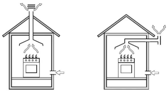
Important: this unit may be installed and used only in permanently ventilated rooms in accordance with British Standard Codes Of Practice: B.S. 6172 / B.S. 5440, Par. 2 and B.S. 6891 Current Editions. The following requirements must be observed:
a) The room must be fitted with a ventilation system which vents smoke and gases from combustion to the outside. This must be done by means of a hood or electric ventilator that turns on automatically each time the hood is operated.
natural_image
Two schematic diagrams of a house interior showing fire extinguishing and heating systems (no text or labels)In a chimney stack or branched flue. Directly to the Outside (exclusively for cooking appliances)
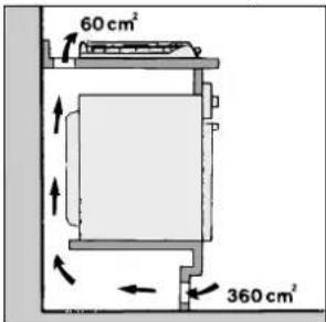
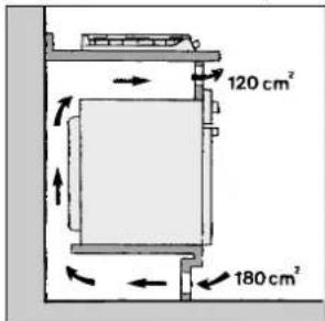
b) The room must also allow for the influx of the air needed for proper combustion. The flow of air for combustion purposes must not be less than 2 m^3/h per kW of installed capacity. The supply of said air can be effected by means of direct influx from the outside through a duct with a inner cross section of at least 100 cm^2 which must not be able to be accidentally blocked. Those appliances which are not fitted with a safety device to prevent the flame from accidentally going out must have a ventilation opening twice the size otherwise required, i.e. a minimum of 200 cm^2 (Fig. A). Otherwise, the room can be vented indirectly through adjacent rooms fitted with ventilation ducts to the outside as described above, as long as the adjacent rooms are not shared areas, bedrooms or present the risk of fire (Fig. B).
Detail A Adjacent Room to be
Room Vented
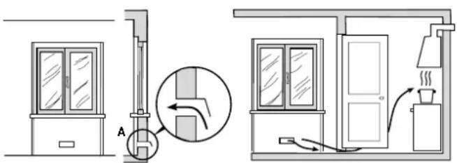
Examples of ventilation holes Enlarging the ventilation slot for comburant air. between window and floor.
Fig. A Fig. B
c) Intensive and prolonged use of the appliance may necessitate supplemental ventilation, e.g. opening a window or increasing the power of the air intake system (if present).
d) Liquidified petroleum gases are heavier than air and, as a result, settle downwards. Rooms in which LPG tanks are installed must be fitted with ventilation openings to the outside in order to allow the gas to escape in the event of a leak. Therefore, LPG tanks, whether empty or partially full, must not be installed or stored in rooms or spaces below ground level (cellars, ect.). It is also a good idea to keep only the tank currently being used in the room, making sure that it is not near sources of heat (ovens, fireplaces, stoves, etc.) that could raise the internal temperature of the tank above 50°C.
Installation of Built-in Cooktops
The appliance can be installed next to furniture units which are no taller than the top of the cooker hob. The wall in direct contact with the back panel of the cooker must be made of non-flammable material. During operation the back panel of the cooker could reach a temperature of 50^ C above room temperature. For proper installation of the cooker, the following precautions must be taken:
a) If the cabinet(s) located next to the cooktop are higher than the cooktop itself, the cabinet(s) must be installed at least 600 mm from the edge cooktop;
b) Hoods must be installed in accordance with the instructions contained in the installation manual for the hoods themselves, and no less than 650 mm from the cooktop;
c) The cabinets installed next to the hood must be located at a height of at least 420 mm from the top, (as shown in Fig. C).
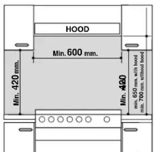
Fig. C
d) Should the cooktop be installed directly under a cupboard, the latter should be at least 700 mm (millimetres) from the top, as shown in Fig. C.
e) The dimensions of the cutout for the appliance must be those indicated in the figure.
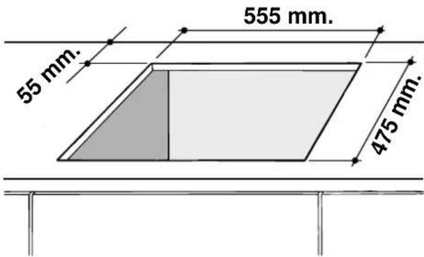
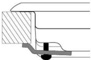
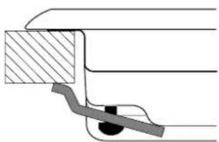
Before fastening the cooktop in place, position the seal (supplied) along the perimeter of the countertop, as shown in the figure.
natural_image
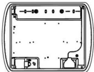
Pure technical diagram of a rectangular device with internal components and mounting holes (no text or symbols)Clamps are provided to fasten the cooktop to counters measuring from 20 to 40 mm in thickness. To fasten the cooktop securely, it is recommended that all the clamps be used.
Fastening Clamps - Assembly Diagram
natural_image
Pure mechanical cross-section diagram without any text, numbers, or symbols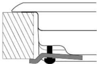
natural_image
Cross-sectional diagram of a mechanical joint or seal assembly (no text or symbols visible)Clamp Position for Clamp Position for
H=30mm top H=40mm top
Front
natural_image
Pure mechanical assembly diagram showing a bracket and lever mechanism without any text or symbols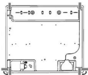
natural_image
Technical line drawing of a mechanical or electronic component with mounting holes and internal structure (no text or symbols)Clamp Position for
H=20mm top Back
N.B: Use the clamps contained in the "accessory kit."
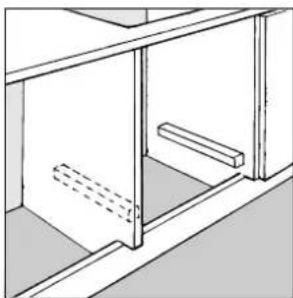
f) In the event the cooktop is not installed above a built-in oven, a wood panel must be inserted as insulation. This panel must be placed at least 20 mm from the bottom of the cooktop itself.
Important: When installing the cooktop above a built-in oven, the oven should be placed on two wooden strips; in the case of a joining cabinet surface, remember to leave a space of at least 45 x 560 mm at the back.
natural_image
Technical line drawing of a cabinet or shelf assembly with no visible text or symbols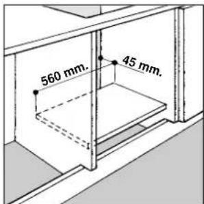
When installing the cooktop above a built-in oven without forced ventilation, ensure that there are air inlets and outlets for ventilating the interior of the cabinet adequately.
Gas Connection for Cooktop
The cooktop should be connected to the gas supply by an authorized installer. During installation of this product it is essential to fit an approved gas tap to isolate the supply from the appliance for the convenience of any subsequent removal or servicing. Connection of the appliance to the gas mains or liquid gas tanks must be carried out according to the safety standards currently in force, and only after it is ascertained that it is suitable for the type of gas to be used. If not, follow the instructions indicated in the section entitled, "Adapting the Cooktop for Different Types of Gas". If the cooktop is to be connected to tanks containing liquid gas, use pressure regulators that comply with current safety standards.
Important: To insure that the appliance operates safety, the gas is regulated correctly and your appliance lasts over time, make sure that gas pressure levels comply with the indications given in Table 1, "Nozzle and Burner Specifications".
Gas Connection to Non-flexible Pipe
(copper or steel)
Connection to the gas source must be done in such a way as to not create any stress points at any part of the appliance.
The appliance is fitted with an adjustable, "L" shaped connector and a gasket for the attachment to the gas supply. Should this connector have to be turned, the gasket must be replaced (supplied with the appliance).
The gas feed connector to the appliance is a threaded, male 1/2" connector for round gas pipe.
Gas Connection to Flexible Steel Pipe
The gas feed connector to the appliance is a threaded, male 1/2" connector for round gas pipe. Only use pipes, tubes and gaskets that comply with current safety codes. The maximum length of the flexible pipes must not exceed 2000 mm. Once the connection has been made, ensure that the flexible metal tube does not touch any moving parts and is not crushed.
Check the Seal
Once the appliance has been installed, make sure all the connections are properly sealed, using a soapy water solution. Never use a flame.
Electrical Connection
The cooktops fitted with a tripolar electrical supply cord are designed to be used with alternating current according to the indications on the rating plate located under the cooktop. The earthing wire can be identified by its yellow-green colour.
In the case of installation over a built-in electric oven, the electrical connections for the cooktop and oven should be independent, not only for safety purposes, but also to facilitate removal of one or both in the future.
Electrical Connection for Gas Cooktop
Fit the supply cord with a standard plug for the demand rate indicated on the rating plate or connect it directly to the electrical mains. In the latter case, a single pole switch must be placed between the appliance and the mains, with a minimum opening between the contacts of 3 mm in compliance with current safety codes (the earthing wire must not be interrupted by the switch). The power supply cord must be positioned so that it does not reach a temperature in excess of 50°C above room temperature at any point.
Before making the actual connection, make sure that:
- The fuse and electrical system can withstand the load required by the appliance;
- That the electrical supply system is equipped with an efficient earth hook-up according to the norms and regulations prescribed by law;
- That the plug or switch is easily accessible.
Important: the wires in the mains lead are coloured in accordance with the following code:
Green & Yellow - Earth
Blue - Neutral
Brown - Live
As the colours of the wires in the mains lead may not correspond with the coloured markings identifying the terminals in your plug, proceed as follows:
Connect the Green & Yellow wire to the terminal marked
"E" or ± or coloured Green or Green & Yellow.
Connect the Brown wire to the terminal marked "L" or coloured Red.
Connect the Blue wire to the terminal marked "N" or coloured Black.
Adapting the Cooktop for Different Types of Gas
To adapt the cooktop to a different type of gas than that for which it was designed, (see the sticker under the hob or on the packaging), the burner nozzles must be changed, as follows:
- Remove the pan supports and slide the burners out of the cooktop.
- Unscrew the nozzles using a 7mm socket wrench and replace them with those for the new type of gas. (See table 1, "Burner and Nozzle Specifications").
- Reassemble the parts following the instructions in reverse order.
- On completing the operation, replace the old rating label with the one showing the new type of gas; the sticker is available from our Service Centres.
If the gas pressure is different than that prescribed, a pressure regulator must be installed at the source, in compliance with national standards governing the use of piped gas regulators.
Regulation of Air Supply to the Burner
The burners do not need a primary air regulator.
Minimum Regulation
Minimum regulation.
- Turn the gas valve to minimum.
- Remove the knob and turn the regulator screw (positioned either on the side of the top or inside the shaft) clockwise until the flame becomes small but regular.
N.B.: In the case of liquid gas, the regulation screw must be fully screwed in (clockwise).
natural_image
Technical illustration of two mechanical components with mounting flanges and fasteners (no text or symbols)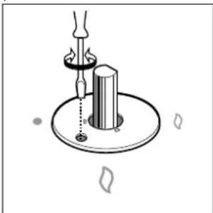
natural_image
Diagram of a mechanical device with a lever and base, showing no text or symbols- Make sure that, when the knob is turned rapidly high to low, the flame does not go out.
- In the event of a malfunction on appliances with the security device (thermocouple) when the gas supply is set at minimum, increase the minimum supply levels using the regulator screw.
Once the adjustment has been made, apply sealing wax, or a suitable substitute, to the old seals on the by-pass.
Burners and Nozzle Specifications
Table 1 Liquid gas Natural gas City gas
| Table 1 Liquid gas Natural gas City gas | ||||||||||||
| Burner Diameter | (mm) | Thermal power kW (p.c.s.*)Nom. Red (1) (mm) | By-pass 1/100 (mm)**** (mm) | Nozzle 1/100 | Flow* g/h | Nozzler 1/100 | Flow* l/h | Nozzler 1/100 (mm) | Flow* l/h | |||
| Reduced Fast (RR) | 100 | 2.60 | 0.7 | 41 | 39 | 80 | 189 | 186 | 110 | 248 | 285 680 | |
| Semi Fast (Medium) (S) | 75 | 1.65 | 0.4 | 30 | 28 | 64 | 120 | 118 | 96 | 157 | 185 374 | |
| Auxiliary (Small) (A) | 55 | 1.00 | 0.4 | 30 | 28 | 50 | 73 | 71 | 71 | 95 | 145 227 | |
| Triple Crown (TC) | 130 | 3.25 | 1.3 | 60 | 57 | 91 | 236 | 232 | 133 | 309 | ||
| Supply pressures | Nominal (mbar)Minimum (mbar)Maximum (mbar) | 28-302035 | 372545 | 201725 | 8615 | |||||||
* At 15°C and 1013 mbar-dry gas
** Propane P.C.S. = 50.37 MJ/kg.
*** Butane P.C.S. = 49.47 MJ/kg.
Natural P.C.S. = 37.78 MJ/m³
(1) Only for appliances with the security device (Ref. F).
TD 730 TC...
TD 740 TC...
TZ 740 TC...
This appliance complies with the following European Economic Community directives:
- 73/23/EEC of 19/02/73 (Low Voltage) and subsequent modifications;
- 89/336/EEC of 03/05/89 (Electromagnetic Compatibility) and subsequent modifications;
- 90/396/EEC of 29/06/90 (Gas) and subsequent modifications;
- 93/68/EEC of 22/07/93 and subsequent modifications.
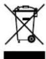
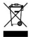
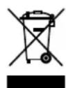
- 2002/96/EEC
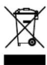
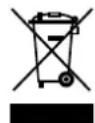
The European Directive 2002/96/EC on Waste Electrical and Electronic Equipment (WEEE), requires that old household electrical appliances must not be disposed of in the normal unsorted municipal waste stream. Old appliances must be collected separately in order to optimise the recovery and recycling of the materials they contain and reduce the impact on human health and the environment. The crossed out “wheeled bin” symbol on the product reminds you of your obligation, that when you dispose of the appliance it must be separately collected.
Consumers should contact their local authority or retailer for information concerning the correct disposal of their old appliance.
natural_image
Illustration of a hand using a tool to brush or brush over scattered particles (no text or symbols)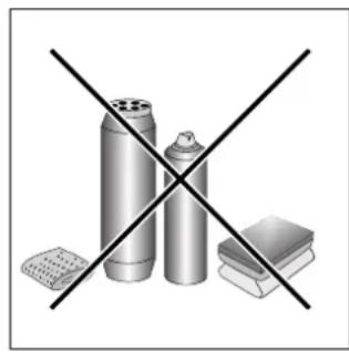
natural_image
Illustration of three metallic containers crossed out by a black X (no text or symbols)Fig. A Fig. B
natural_image
Simple line drawing of a heating room setup with a stove, air conditioner, and cooling unit (no text or symbols)natural_image
Simple line drawing of a house interior with a stove, air ducts, and ventilation system (no text or symbols)natural_image
Technical line drawing of a device casing with internal components and mounting holes (no text or symbols)natural_image
Technical diagram of a mechanical assembly with cross-hatched and shaded components (no text or labels)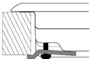
natural_image
Cross-sectional diagram of a mechanical assembly with hatched fill and central component (no text or labels)natural_image
Technical line drawing of a cabinet or shelf assembly with no visible text or symbols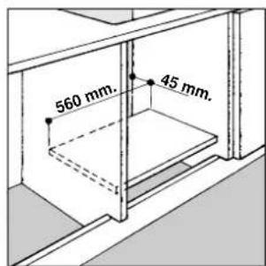
Raccordement gaz (Pour la France)
natural_image
Technical illustration of two mechanical components with base plates and adjustment knobs (no text or symbols)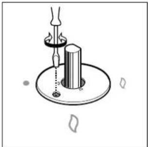
natural_image
Diagram of a mechanical setup with a rotating shaft and base, no text or symbols present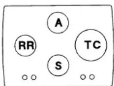

natural_image
Illustration of a hand using a tool to brush or paint onto a surface, with no visible text or symbols.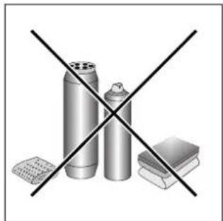
natural_image
Illustration of three metallic cylindrical objects crossed with a black 'X' line, next to stacked books (no text or symbols)Afb. A Afb. B
natural_image
Two schematic diagrams of a house interior with steam heating and ventilation systems (no text or labels)Afb. C
natural_image
Pure technical diagram of a mechanical or electrical component outline without any text, numbers, or symbolsnatural_image
Technical diagram showing two mechanical assembly configurations with hatched areas indicating material sections (no text or symbols)natural_image
Technical line drawing of a mechanical assembly with cross-sectional and top views (no text or symbols)Aansluiten gas
natural_image
Two mechanical components with cylindrical pins and connecting rods, shown from different angles (no text or symbols)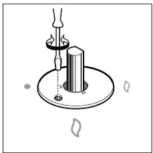
natural_image
Diagram of a mechanical setup with a cylindrical component and a lever, no text or symbols present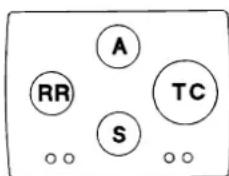

natural_image
Illustration of a hand using a paintbrush to brush residue in a circular container (no text or symbols)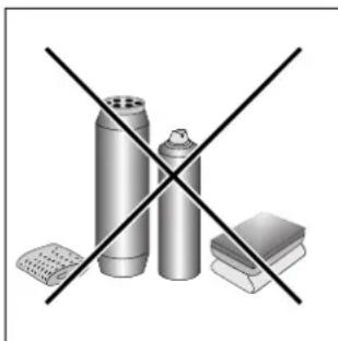
natural_image
Illustration of three metallic containers crossed with a black X symbol, no text or labels presentFig. A Fig. B
natural_image
Two schematic diagrams of a greenhouse with steam rising from the top, showing internal air flow and heating elements (no text or labels)natural_image
Pure technical diagram of a mechanical or electrical component outline without any text, numbers, or symbolsnatural_image
Pure mechanical assembly diagrams showing two cross-sectional views of a bracket or mounting base (no text or symbols)natural_image
Technical line drawing of a mechanical assembly with cross-sectional and top views (no text or symbols)natural_image
Technical line drawing of a cabinet or shelf assembly with structural beams and a dashed-line component (no text or symbols)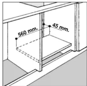
Conexión gas
natural_image
Two identical mechanical components with cylindrical bases and a flame-like top, shown without any text or symbols.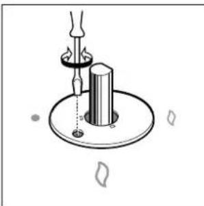
natural_image
Diagram of a mechanical device with a central shaft and base, showing alignment or positioning (no text or symbols)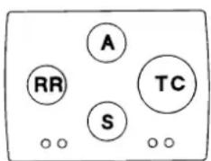

natural_image
Illustration of a hand using a paintbrush to brush residue in a circular container (no text or symbols)
natural_image
Illustration of three metallic cylindrical objects crossed with a black X mark, no text or symbols presentFig. A Fig. B
natural_image
Two schematic diagrams of a greenhouse with steam rising from the top, showing internal heating and cooling systems (no text or labels)natural_image
Technical line drawing of a mechanical housing or enclosure with internal components and mounting holes (no text or symbols)natural_image
Pure mechanical cross-section diagrams without any text, numbers, or symbolsnatural_image
Two mechanical components with cylindrical bodies and mounting flanges, no text or symbols present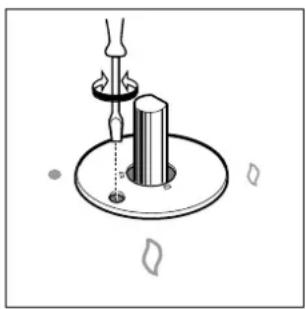
natural_image
Mechanical diagram showing a lever and rotating component mounted on a circular base (no text or symbols)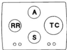

natural_image
Illustration of a hand using a paintbrush to brush the paint onto a surface, with scattered debris (no text or symbols)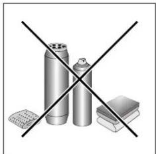
natural_image
Illustration of three metallic containers crossed with a black X mark, next to stacked books (no text or symbols)Abb. A Abb. B
natural_image
Two schematic diagrams of a greenhouse with steam rising from the top, showing internal air and heating elements (no text or labels)natural_image
Technical line drawing of a device casing with internal components and mounting holes (no text or symbols)natural_image
Technical diagram showing two mechanical assembly configurations with hatched areas indicating material sections (no text or symbols)natural_image
Technical line drawing of a cabinet or shelf with two horizontal bars and a dashed-line floor (no text or symbols)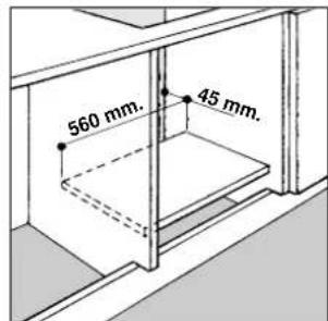
natural_image
Two mechanical components with cylindrical heads and connecting rods, shown from different angles (no text or symbols)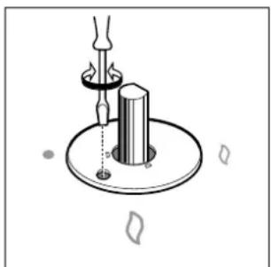
natural_image
Diagram of a mechanical device with a cylindrical component mounted on a circular base, no visible text or symbols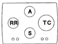

- Close-up View
- How To Use Your Appliance
- Gas Burners
- How to Keep Your Cooktop in Shape
- Greasing the Taps
- Practical Advice
- Practical Advise on Using the Burners
- Is there a problem?
- The burner does not light or the flame is not uniform around the burner.
- The flame does not stay lighted on the model with the safety device.
- The burner does not remain on when set to "Low".
- The cookware is not stable.
- Safety Is a Good Habit to Get Into
- Prevent children and the disabled from coming into contact or having access to the following, as they are possible sources of danger:
- The following should be avoided:
- The assistance of qualified personnel must be called upon in the following cases:
- Contact service centers authorized by the manufacturer in the following cases:
- It is recommended that you follow the guidelines below:
- Installation Instructions for built-in
- Positioning the Cooktop
- Installation of Built-in Cooktops
- Gas Connection for Cooktop
- Gas Connection to Non-flexible Pipe
- Gas Connection to Flexible Steel Pipe
- Check the Seal
- Electrical Connection
- Electrical Connection for Gas Cooktop
- Blue - Neutral
- Brown - Live
- Adapting the Cooktop for Different Types of Gas
- Regulation of Air Supply to the Burner
- Minimum Regulation
- Burners and Nozzle Specifications
- This appliance complies with the following European Economic Community directives:
- Raccordement gaz (Pour la France)
- Aansluiten gas
- Conexión gas
Brand : Ariston Thermo
Model : TD 740 TC ES BK
Category : Cooker