
THERserie - Boiler Ariston Thermo - Free user manual and instructions
Find the device manual for free THERserie Ariston Thermo in PDF.

| Product type | Electric water heater (storage tank) |
| Available ranges | THER, STEA, PTEC, ZEN, HPC, QUIE |
| Power supply | Single-phase 230V or three-phase 400V depending on model |
| Required differential protection | 30 mA circuit breaker |
| Electrical connection | Min. cable cross-section 3x2.5 mm² (single-phase) or 4x2.5 mm² (three-phase) up to 3000 W |
| Operating pressure | Indicated on rating plate |
| Required safety unit | Yes, conforming to EN 1487, 7 bar, mounted on cold water inlet |
| Hydraulic connection | Dielectric fittings mandatory on copper; PER prohibited |
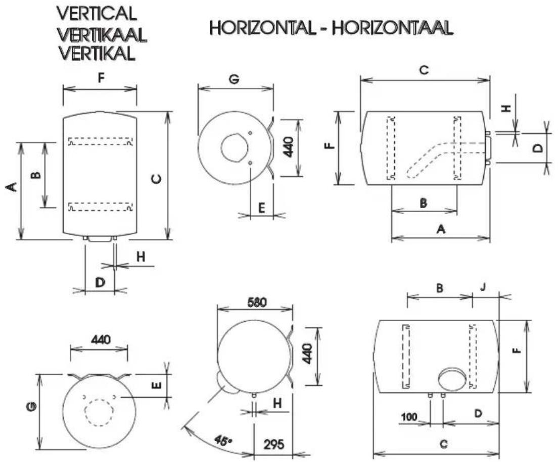
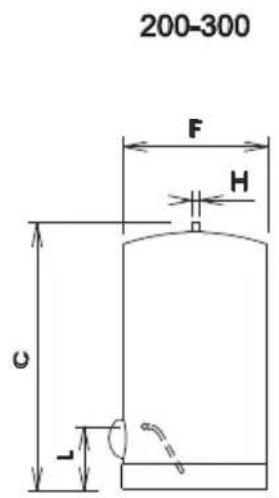
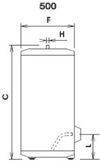
| Dimensions (approximate) | See page 2 of the manual |
| Weight (approximate) | Varies by capacity |
| Available capacities | Vertical, horizontal, on pedestal from 50 to 500 L |
| Heating element type | Immersion (THER range) or steatite (STEA, PTEC, ZEN, HPC, QUIE ranges) |
| Anti-corrosion protection | Enamelled tank + magnesium anode (or titanium anode PROfessional TECH) |
| PROfessional TECH system | Electronic anti-corrosion protection with modulated current (permanent power supply or battery) |
| Set temperature | Adjustable, recommended at 60°C with mixer to prevent burns |
| Recommended annual maintenance | Draining, descaling, magnesium anode check, replacing base gasket |
| Cleaning | Clean tank without metal objects or chemical agents |
| Safety | Cut power before intervention; operate safety unit monthly; thermostat with thermal safety |
| Spare parts | Heating element, anode, gasket, thermostat, electronic circuit (PTEC), Ni-Mh 9V battery |
| Repairability | Interventions by qualified professional; thermostat resettable max 3 times; replace heating element if zero or infinite resistance |
| Warranty | Subject to conditions of proper installation and maintenance; excludes abnormal corrosion, scaling, lack of retention tray |
| Recycling | Selective sorting (crossed-out bin); taken to a waste collection center or returned to retailer |
Frequently Asked Questions - THERserie Ariston Thermo
User questions about THERserie Ariston Thermo
0 question about this device. Answer the ones you know or ask your own.
Ask a new question about this device
Download the instructions for your Boiler in PDF format for free! Find your manual THERserie - Ariston Thermo and take your electronic device back in hand. On this page are published all the documents necessary for the use of your device. THERserie by Ariston Thermo.
USER MANUAL THERserie Ariston Thermo
Thank you for choosing this appliance! Welcome to the ever-growing family of satisfied customers using our products throughout the world.
We are sure that you will benefit – and gain great satisfaction - from using this appliance. We would advise that you read this manual carefully, and that you keep it in a safe and easily accessible place.
This booklet must be retained for the entire working life of the appliance to which it refers.
Booklet in English see page 45.
The manufacturer reserves the right to make all modifications deemed necessary for the improvement of the product.
| I - CARACTERISTIQUES TECHNIQUES MODELESnet | Pertes statiques Qpr | DIMENSIONS EN mm Poids | ||||||||||
| I - TECNISCHE KENMERKEN MODELLEngewicht | Statische lossen | AFMETINGEN IN mm Netto | ||||||||||
| I - TECNISCHE MERKMALE MODELLEgewich | Bereitschafts -Energieverbrauch | ABMESUUNGEN IN mm Netto | ||||||||||
| I - TECHNICAL CHARACTERISTICS MODELSweight | Static losses | DIMENSIONS IN mm Net | ||||||||||
| kWh/24h à 65°C | A B C | D E F G H | J L kg | |||||||||
| GAMME STEATITE & PROFessional TECH - STEATITE GAMMA & PROFessional TECH - SERIE STEATIT & PROFessional TECH - CERAMIC CORE ELEMENT & PROFessional TECH - GAMMA ESTEATITA & PROFessional TECH - GAMMA STEATITE & PROFessional TECH - GAMMA ESTEATITE & PROFessional TECH Vertical - Vertikaal - Vertikal - Verticale | ||||||||||||
| 050 VERT 460 STEA MO - GE | 0,89 | 410 | - | 560 | 160 | 120 | 460 | 475 | G1/2 | - | - | 18 |
| 075 VERT 460 STEA MO - GE | 1,20 | 590 | - | 760 | 230 | 175 | 460 | 475 | G3/4 | - | - | 24 |
| 075 VERT 460 PTEC MO - GE | 1,20 | 590 | - | 790 | 230 | 175 | 460 | 475 | G3/4 | - | - | 24 |
| 100 VERT 505 STEA MO | 1,30 | 560 | - | 830 | 230 | 175 | 505 | 510 | G3/4 | - | - | 31 |
| 150 VERT 505 STEA MO / TR | 1,70 | 1050 | 800 | 1150 | 230 | 175 | 505 | 510 | G3/4 | - | - | 39 |
| 200 VERT 505 STEA MO / TR | 2,17 | 1050 | 800 | 1480 | 230 | 175 | 505 | 575 | G3/4 | - | - | 47 |
| 100 VERT 560 STEA MO / PTEC / DIY / HPC * | 1,05 / 1,03* | 530 | - | 750 | 230 | 175 | 560 | 575 | G3/4 | - | - | 31 |
| 150 VERT 560 STEA MO / TR / PTEC / DIY / HPC * | 1,54 / 1,41* | 750 | 500 | 1010 | 230 | 175 | 560 | 575 | G3/4 | - | - | 39 |
| 200 VERT 560 STEA MO / TR / PTEC / DIY / HPC * | 1,85 / 1,85* | 1050 | 800 | 1270 | 230 | 175 | 560 | 575 | G3/4 | - | - | 47 |
| 100 VERT 530 HPC MO | 1,06 | 560 | - | 835 | 230 | 175 | 530 | 545 | G3/4 | - | - | 32 |
| 150 VERT 530 HPC MO | 1,35 | 1050 | 800 | 1160 | 230 | 175 | 530 | 545 | G3/4 | - | - | 40 |
| 200 VERT 530 HPC MO | 1,76 | 1050 | 800 | 1480 | 230 | 175 | 530 | 545 | G3/4 | - | - | 49 |
| Sur socle - Op sokkel - Auf sockel - Free standing - Sobre zocalo - Su zoccolo - No suporte | ||||||||||||
| 200 STAB 560 STEA MT | 1,88 | - | - | 1300 | - | - | 560 | 625 | G3/4 | - | 390 | 54 |
| 250 STAB 560 STEA MT | 2,17 | - | - | 1540 | - | - | 560 | 625 | G3/4 | - | 365 | 61 |
| 300 STAB 560 STEA MT | 2,60 | - | - | 1800 | - | - | 560 | 625 | G3/4 | - | 365 | 75 |
| 200 STAB 560 STEA PTEC MT | 1,88 | - | - | 1300 | - | - | 560 | 650 | G3/4 | - | 390 | 54 |
| 300 STAB 560 STEA PTEC MT / DIY | 2,60 | - | - | 1800 | - | - | 560 | 650 | G3/4 | - | 365 | 75 |
| 250 STAB 570 HPC MT | 2,17 | - | - | 1670 | - | - | 570 | 660 | G3/4 | - | 380 | 55 |
| 270 STAB 570 HPC MT - QUIE - ZEN | 2,30 | - | - | 1800 | - | - | 570 | 660 | G3/4 | - | 380 | 64 |
| 300 STAB 570 HPC MT - QUIE - ZEN | 2,45 | - | - | 1950 | - | - | 570 | 660 | G3/4 | - | 380 | 77 |
| HORIZONTAL - HORIZONTAAL - ORIZZONTALE | ||||||||||||
| 100 HORB 560 STEA MO | 1,65 | - | 280 | 750 | 320 | - | 560 | - | G3/4 | 260 | - | 30 |
| 150 HORB 560 STEA MO | 2,25 | - | 500 | 1010 | 460 | - | 560 | - | G3/4 | 260 | - | 38 |
| 200 HORB 560 STEA MO | 2,68 | - | 800 | 1270 | 580 | - | 560 | - | G3/4 | 260 | - | 46 |
| GAMME BLINDEE - BARKERBUIS GAMMA - GESCHLOSSENE AUSFÜHRUNG - STEEL ALLOY ELEMENT - GAMA BLINDADA - GAMME BLINDATA - GAMMA BLINDADA Vertical - Vertikaal - Vertikal - Verticale | ||||||||||||
| 050 VERT 460 THER MO - GE | 0,89 | 410 | - | 560 | 160 | 120 | 460 | 475 | G1/2 | - | - | 17 |
| 075 VERT 460 THER MO - GE | 1,19 | 590 | - | 760 | 230 | 175 | 460 | 475 | G3/4 | - | - | 23 |
| 100 VERT 505 THER MO | 1,32 | 560 | - | 830 | 230 | 175 | 505 | 510 | G3/4 | 29 | ||
| 150 VERT 505 THER MO / TR | 1,72 | 1050 | 800 | 1150 | 230 | 175 | 505 | 510 | G3/4 | - | - | 37 |
| 200 VERT 505 THER MO / TR | 2,15 | 1050 | 800 | 1480 | 230 | 175 | 505 | 510 | G3/4 | - | - | 45 |
| 100 VERT 560 THER MO | 1,03 | 530 | - | 750 | 230 | 175 | 560 | 575 | G3/4 | - | - | 29 |
| 150 VERT 560 THER MO | 1,41 | 750 | 500 | 1010 | 230 | 175 | 560 | 575 | G3/4 | - | - | 37 |
| 200 VERT 560 THER MO | 1,85 | 1050 | 800 | 1270 | 230 | 175 | 560 | 575 | G3/4 | - | - | 45 |
| Sur socle - Op sokkel - Auf sockel - Free standing - Sobre zocalo - Su zoccolo | ||||||||||||
| 200 STAB 560 THER MT | 1,88 | - | - | 1300 | - | - | 560 | 625 | G3/4 | - | 390 | 50 |
| 250 STAB 560 THER MT | 2,17 | - | - | 1540 | - | - | 560 | 625 | G3/4 | - | 365 | 61 |
| 300 STAB 560 THER MT | 2,6 | - | - | 1800 | - | - | 560 | 625 | G3/4 | - | 365 | 71 |
| 500 STAB 714 THER MT | 3,60 | - | - | 1870 | - | - | 714 | - | G1" | - | 335 | 95 |
| HORIZONTAL - HORIZONTAAL - ORIZZONTALE | ||||||||||||
| 100 HORD 505 THER MO | 1,94 | 560 | 345 | 830 | 230 | 175 | 505 | 510 | G3/4 | - | - | 30 |
| 150 HORD 505 THER MO | 2,17 | 1050 | 235 | 1150 | 230 | 175 | 505 | 510 | G3/4 | - | - | 38 |
| 200 HORD 505 THER MO | 2,66 | 1050 | 800 | 1460 | 230 | 175 | 505 | 510 | G3/4 | - | - | 46 |
| 75 HORD 460 THER MO - GE | 1,69 | 590 | 370 | 760 | 230 | 175 | 460 | 475 | G3/4 | - | - | 23 |
| 100 HORD 560 THER MO | 1,37 | 530 | 280 | 750 | 230 | 175 | 560 | 575 | G3/4 | - | - | 30 |
| 150 HORD 560 THER MO | 1,87 | 750 | 500 | 1010 | 230 | 175 | 560 | 575 | G3/4 | - | - | 38 |
| 200 HORD 560 THER MO | 2,07 | 1050 | 800 | 1270 | 230 | 175 | 560 | 575 | G3/4 | - | - | 46 |
| 100 HORB 560 THER MO | 1,65 | - | 280 | 750 | 320 | - | 560 | - | G3/4 | 260 | - | 30 |
| 150 HORB 560 THER MO | 2,25 | - | 500 | 1010 | 460 | - | 560 | - | G3/4 | 260 | - | 38 |
| 200 HORB 560 THER MO | 2,68 | - | 800 | 1270 | 580 | - | 560 | - | G3/4 | 260 | - | 46 |
* Valeur pour gamme HPC (d560) - wearde voor reeks HPC (d560) - value for HPC (d560) range - wert für HPC (d560) bereich
Tab caract big neutre
SOCLE - OP SOKKEL - AUF SOCKET - FREE STANDING
INTRODUCTION 9
1. PRÉSENTATION DU PRODUIT 9
PROfessional TECH - HPC - QUIE
natural_image
3D rendered mechanical component with bolts and a nut, no text or symbols visiblenatural_image
Simple line drawing of a cylindrical object with a base, no text or symbols presentFigure 15a- Interface ZEN
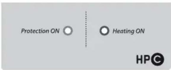
Figure 15b- Interface HPC - QUIE
2. Incidents, causes et actions
natural_image
Close-up of mechanical components with wires and bolts, no visible text or symbolsnatural_image
3D rendered mechanical component with bolts and a nut, no text or symbols visible2.2.b. Verticaal wandmodel VERT
natural_image
Simple line drawing of a cylindrical object with a flat top and base (no text or symbols)4.4. PROfessional Tech (PTEC) - HPC - QUIE
natural_image
Close-up of mechanical components with wires and bolts, no visible text or symbolsnatural_image
Simple line drawing of a trash bin with crossed lines indicating no waste or discharge (no text or symbols)natural_image
3D rendered mechanical component with bolts and a nut, no text or symbols visiblenatural_image
Simple line drawing of a cylindrical object with a base, no text or symbols presentnatural_image
Close-up of mechanical components with wires and bolts, no visible text or symbols- Cut off the electricity supply before performing any work on the appliance.
- This appliance can be used by children aged from 8 years and above and persons with reduced physical, sensory or mental capabilities or lack of experience and knowledge if they haven been supervision or instruction concerning use of the appliance in a safe way and understand the hazards involved. Children shall not play with the appliance. Cleaning and user maintenance shall not made by children without supervision.
- The elements comprising the packaging must be removed from the reach of children as they can constitute a source of danger.
- The installation of the water heater, appliance preparation, maintenance work and repair work may only be carried out by qualified personnel. These individuals must act in accordance with current national legislation. In particular, all regulations relating to water heaters must be fully observed.
- CAUTION: The appliance must never be powered when it is empty, as this could damage the electrical components.
➢ Fill the boiler by opening the water inlet valve on the safety assembly.
➢ Open the hot water tap so that the air cushion which has accumulated inside the water heater may be expelled.
➢ Close the hot water tap as soon as water begins to come out of it.
➢ Make sure the base and the attachment seals are watertight. Where necessary, re-tighten the bolts on the base (recommended between 7 and 10 Nm – dynamometric spanner) or the attachments.
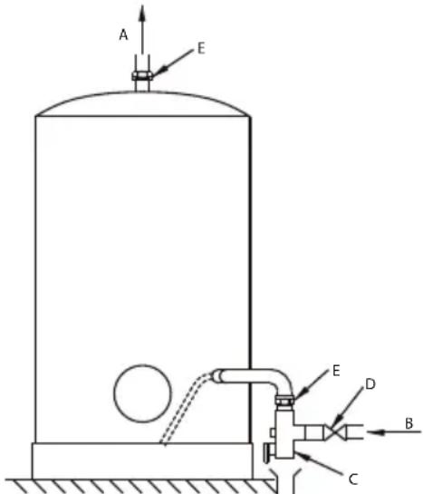
- The water heater must be fitted with a safety assembly which conforms to current national legislation(EN 1487), with pressure 7 bars-0.7MPa, connected to the cold water pipe.
The safety assembly must be fitted as close as possible to the cold water inlet of the water heater and THE PASSAGE OF WATER MUST NEVER BE PREVENTED by any type of accessory.
If, for technical reasons, the safety assembly cannot be installed with a direct connection to the cold water inlet,(max 50 cm) the installed connection must be rigid and must always be made using material which is able to withstand pressures of at least 7 bar and high temperatures.
The drainage outlet of the safety assembly must never be obstructed and must be connected to a vertical drainage pipe with a diameter which is at least equal to that of the appliance connection piping, with a funnel which creates an empty space of at least 20 mm leading outwards. This piping must be installed in a room which is not subject to icy conditions, sloping downwards.
Use always new pipes to connect the appliance at water network.
- Due to the expansion of water during the heating stage, dripping from the safety assembly (up to 3% of the nominal capacity) is normal. Please read the instructions for the safety
assembly. An expansion vessel may be installed in order to prevent this leakage.
- Activate the tap and the valve on the safety assembly every month so as to prevent limescale from building up. Replace the safety assembly at least once every 5 years or, if necessary, more frequently.
- The appliance and its safety assembly must be installed in a room which is not subject to freezing conditions.
When performing maintenance work, the following should be provided:
- a free space of at least 50 cm in front of the plastic cover so that the electrical components may be accessed;
- direct access to the safety assembly.
- For safety reasons, if away from the premises, users must turn the hydraulic and electric circuits off, as well as drain the appliance.
➢ Cut off the electricity supply before performing any work on the appliance.
▶ Shut off the cold water supply at the inlet.
▶ Open the hot water tap to draw water.
➢ Open the emptying valve on the safety assembly and the water will flow out of the drainage hole.
- To prevent burns from occurring, use suitable mixers which ensure that the temperature does not exceed 50^ at the drawing points and 60^ for the kitchen.
- Recommendations for installation in a bathroom environment:
The water heater installation in the bathroom must be adapted in accordance with national rules and standards in force (NFC 15-100, RGIE, etc.).
➢ The system must be fitted with a switch which has an opening of 3 mm between contacts. The circuit must be protected by fuses or switches which are calibrated according to the power of the water heater.
The electric water heater must be connected in accordance with European regulations and the connections must always conform to current national legislation. The line must be protected by a 30 mA differential switch.
The electrical connection of a fixed appliance should be performed using a suitable rigid wire with an appropriate cross-section and a green/yellow earth wire: please consult current national legislation relating to electrical systems (the minimum requirement will be 3 × 2.5 mm^2 singlephase and 4 × 2.5 mm^2 three-phase for a power level of up to 3000 W).
• CAUTION: the appliance MUST be earthed!
Do not use piping for an earth connection.
- If the appliance is supplied with rechargeable batteries, these must be removed before the appliance is discarded and disposed of in a safe manner. The batteries must be removed from the support structure located in the area which can be accessed from underneath the plastic cover.
- The manufacturer shall not be held liable for any damage caused to persons, animals or other things, by unprofessional or improper installation, or by failure to comply with current legislation or the instructions contained in this booklet.
INTRODUCTION 48
1. INTRODUCTION TO THE PRODUCT 48
1.1. Regulations relating to transportation, storage and recycling 48
1.2. Dimensions 48
1.3. THER armoured range 48
1.4. STEA steatite range 48
1.5. PROfessional TECH PTEC steatite range - HPC - QUIE 48
INSTALLATION 49
1. LEGAL OBLIGATIONS AND RECOMMENDATIONS RELATING TO PRODUCT INSTALLATION DEFINITION AUTHORISED FIXING AREAS FOR THE WATER HEATER 49
2. INSTALLING THE PRODUCT 50
2.1. Material required 50
2.2. Assembly 50
3. HYDRAULIC CONNECTION 52
4.1. Important considerations 52
4.2. VERT, HORD, HORB three-phase vertical model, MT version 52
4.3. STAB MT stable model 52
4.4. PROfessional TECH PTEC - HPC - QUIE 52
4. ELECTRICAL CONNECTION 52
OPERATION 53
- INTRODUCTION 53
1.1.User considerations 53 - OPERATING ADVICE 53
2.1. Temperature adjustment 53
2.2. Maintenance 53
2.3. Indicator lights 53
MAINTENANCE AND REPAIRS 54
1. MAINTENANCE 54
- Build-up removal – Checking the anode 54
- PROBLEMS, CAUSES AND SOLUTIONS 55
GUARANTEE CONDITIONS 57
INTRODUCTION
1. Introduction to the product
1.1. Regulations relating to transportation, storage and recycling
- The appliance must be transported in accordance with the pictograms printed on the packaging.
- The appliance must be transported and stored in dry conditions where it will not be subjected to freezing.
- The EU Directive 2002/96/EC sets out the obligation to perform separated waste collection and to recycle all electrical and electronic equipment.
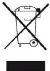
GB
The “crossed-out dustbin” symbol on the appliance indicates that when the product is no longer in good working condition, it should not be disposed of in the same manner as normal household waste. Instead, it should be taken to a separated waste collection centre which deals with electrical and electronic equipment or reclaimed by the distributor when a new appliance has been purchased to replace it.
Separated waste collection, which ensures the appliance is recycled once it has reached the end of its life cycle, helps to avoid any negative effects on the environment and encourages the recycling of the individual materials used to manufacture the appliance.
To find out more about existing waste collection centres, please contact the waste collection service in your local area, or the shop from which the appliance was originally purchased. 4. The packaging protects the water heater from any damage which may occur during transportation. We use materials which have been specifically selected in order to help protect the environment. We invite you to take these materials to the nearest recycling centre or the nearest recyclable materials collection point.
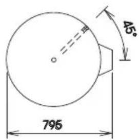
1.2. Dimensions
See page 2.
All our appliances conform to the EMC Directive 89/336/EEC.
All our boilers are constructed using steel which conforms to the regulation NF A36-301.
The protective internal coating in our boilers is made using enamel which has been vitrified at a high temperature.
1.3. THER armoured range
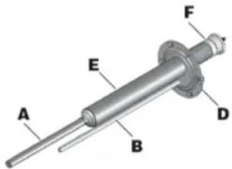
1.3.a. Definition of the range Heating element: Immersion heating element Anti-corrosion protection: Enamelled boiler + magnesium anode
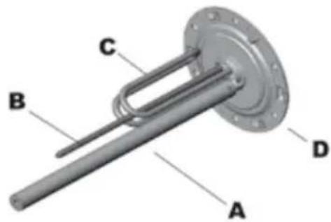
Picture 1- Immersion heating element + magnesium anode
1.3.b. Technical features See page 6.
1.4. STEA steatite range
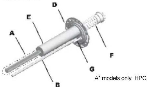
1.4.a. Definition of the range Heating element: Steatite heating element located inside a bush Anti-corrosion protection: Enamelled boiler + magnesium anode
Picture 2- Steatite heating element + magnesium anode
1.4.b. Technical features See page 6.
1.5. PROfessional TECH PTEC steatite range - HPC - QUIE
1.5.a. Definition of the range
Heating element: Steatite heating element located inside a bush
Anti-corrosion protection: Enamelled boiler + PROfessional TECH anode - HPC - QUIE
The exclusive PROfessional TECH system solution is an anodic anti-corrosion electronic protection system with a modulated current. It ensures maximum durability in terms of the boiler used in the water heater, regardless of whether more or less aggressive water is used. The electronic circuit creates a difference in potential between the boiler and the titanium electrode, so that optimal boiler protection is guaranteed, thereby preventing its corrosion.
Picture 3- Steatite heating element + PROfessional TECH anode
1.5.b. Technical features See page 6.
INSTALLATION
1. Legal obligations and recommendations relating to product installation
Before installing this appliance, please read the instructions contained in this manual carefully. Failure to observe these instructions may lead to the guarantee becoming void.
-
All product installation and maintenance work must only be performed by qualified professionals. Current national legislation must be observed. In particular, all regulations relating to water heaters must be fully observed.
-
The manufacturer shall not be held liable for any damage caused by unprofessional or improper installation, or by failure to comply with the instructions contained in the user manual.
-
If the appliance is installed in a room which is just above an inhabited space (a loft, attic, false ceiling, etc.), insulate the piping and fit a retention tank with water drainage. Connection
to the sewage system is compulsory in all instances.
Advice To avoid excessive energy consumption, we recommend that the water heater is positioned as close as possible to the hot water drawing points (recommended distance: no greater than 8 metres).
Recommendation when installing in the bathroom:
The water heater installation in the bathroom must be adapted in accordance with national rules and standards in force (NFC 15-100, RGIE, etc.).
Volume classifications:
➢ Volume 0: This is the interior volume of the bathtub or shower tray.
Volume 1: This is the volume outside that bathtub or shower tray and is limited on the one side by the vertical cylindrical surface circumscribed to the edge of the bathtub or shower tray, and on the other by the horizontal plane at 2.25 m from the bottom of the bath or shower base.
Volume 2: This is the volume external to volume 1. It is limited by the vertical cylindrical surface 0.60m from the edge of the bathtub or shower tray and limited by a horizontal plane at 2.25 m above the bottom of the bathtub or shower tray.
Volume 3: This is the volume external to volume 2. It is limited by the vertical cylindrical surface 2.40m from volume 2 and limited by a horizontal plane at 2.25 m above the bottom of the bathtub or shower tray.

Authorised water heater fixing zones:
Fixed, low voltage water heaters are permitted in volume 1 as long as they have maximum protection level (IPX4). Please note: horizontal type water heaters, installed as high up as possible in volume 1 are permitted for France only.
A : Magnesium anode / B : Spike / C : Immersion heating element / D : Plate / E : Bush / F : Steatite heating element / G : PROfessional TECH anode.
1 « This regulation applies in France and the installer must keep up to date with all subsequent modifications. For installation in other countries, please refer to applicable local regulations.».
Only fixed water heaters which have a protection degree of at least IP 24 are permitted within the protection volume (B).
2. Installing the product
2.1. Material required
2.1.a. Tools and materials which should be provided
➢ If the wall cannot withstand the weight of the water heater a support or a ceiling fixing kit.
➢ If you wish to fix a horizontal model to a wall or to a ceiling a set of fixing straps.
For the seal : hemp/tow and sealing paste or a seal for connections to be screwed in, depending on the model.
Spirit level.
If the water heater is fitted with fixing brackets:
For each fixing bracket 2 rawlplugs and 2 bichromate concrete screws, Fischer M10, M12 or M14 type.
➢ Material necessary for drilling with M10, M12 or M14 diameter.
➤ Dynamometric spanner.
Nuts with M10, M12 or M14 diameter.
➢ Washer with M10, M12 or M14 diameter.
2.1.b. Accessories
Indispensable accessories:
Safety assembly (suited to the model).
Dielectric connection(s).
➢ If the water pressure is greater than 4.5 bar ⇒ a pressure reducer.
Others:
Cut-off valve.
Domestic hot water expansion vessel.
Mixer which helps to prevent the risk of burns, as the temperature does not exceed 50^ C at the drawing points and 60^ C in the kitchen (this is a legal obligation in France).
2.2. Assembly
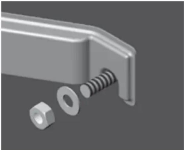
2.2.a. General instructions for the fixing brackets Fix the support bracket(s) to a load-bearing wall using suitable fastening bolts measuring 10 mm in diameter and flat steel washers measuring a minimum of 24 mm and a maximum of 30 mm in (external) diameter.
IMPORTANT: MAKE SURE THAT THE NUT IS WELL TIGHTENED
natural_image
3D rendered mechanical component with bolts and a nut, no text or symbols visiblePicture 5 - Fitting the fixing bracketInstallation values
2.2.b. VERT Vertical wall-fitted model
Position the appliance at least 50 cm from the floor and at least 5 cm from the ceiling to facilitate maintenance work. (Picture 6)
This model can also be installed on a support (optional), but it absolutely must be fixed to a load-bearing wall with the upper fixing bracket.
Make sure that the installed support is suitable for the model of water heater and diameter in question, and that it is correctly assembled and installed.
Advice We recommend the use of a support which is compatible with the products designed by this manufacturer.
Advice Use the installation template printed on the packaging of the water heater.
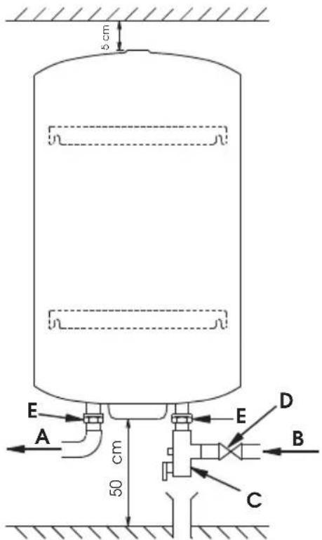
Picture 6 - Installation values
2.2.c. HORD horizontal model
This appliance is designed to be fitted to the wall horizontally, with the two fixing brackets attached to the wall (Picture 7-8). It can also be installed on the floor or the ceiling if necessary, using a set of straps (optional).
In this situation, please consult the installation instructions supplied with the set of straps.
HORDroit version with water inlet and outlet pipes on the protection element
The model is already prepared at the company so that it can be installed horizontally onto a wall; the supply pipes are located on the right-hand side of the appliance (Picture 7).
Picture 7 - Horizontal element on the protection element - supply pipes on the right-hand side
If the pipes are positioned on the left-hand side, it is absolutely fundamental that the electric base is removed to position the immersion heating element in the lower part of the appliance. Invert the blue and red piping reference clips (Picture 8 and 9). Hot water connection must be performed on the upper piping.
Picture 8 - Heating element assembly for left-hand side models HORD
Picture 9 - Horizontal element on the protection element - supply pipes on the left-hand side
HORBas HORB version with water inlet and outlet pipes on the bodywork ring nut
This appliance is designed to be fitted to the wall horizontally; the supply pipes are located at the base (Picture 10).
Picture 10 - Horizontal model on ring nut
2.2.d. STAB models on base structures
This appliance is fitted with a base structure which is fixed to the product while it is still at the company. Position the appliance on a perfectly flat and level surface.
natural_image
Simple line drawing of a cylindrical container with a base, no text or symbols present.Picture 11 - Model on base structure
Picture 12 - Model on base structure
3. Water connection
- The operating pressure is indicated on the data plate of the water heater (see water heater).
- Connection with materials synthesis PER are prohibit: flood risk
To connect the tank on plastic pipe "PER" installation existent, intercalate on the out-let (hot water) a copper pipe with minimum longer 50 cm to avoid any damage.
The connection of a water heater to copper piping must be performed using a dielectric connection. These dielectric connections are available as an optional extra or as standard, depending on the model purchased.
If you only have one dielectric connector, you must fit it to the hot water outlet!
- When the input pressure of the network is greater than 4.5 bar, a pressure reducer must be
installed upstream of the safety assembly.
- If the water systems have the following features:
small pipes;
- taps with ceramic plates / mixer taps; a “ram stabilising” device or a domestic hot water expansion vessel suited to the system must be installed as close as possible to the taps.

We recommend that a shut-off valve is installed upstream from the safety assembly.
See pictures 6, 7, 8, 9, 10, and 12.
4. Electrical connection
4.1. Important considerations
THE WIRING DIAGRAM IS STUK ONTO THE APPLIANCE: USE IT AS A REFERENCE GUIDE.
4.2. VERT, HORD, HORB three-phase vertical model, MT version
Three-phase vertical appliances are already wired at 400 V THREE-PHASE when they are shipped. They may be connected at 230 V Three-phase or 230 V SINGLE-PHASE (see scheme of electrical connections on apparatus).
4.3. STAB MT stable model
The 200-250 & 300 litre stable models are already wired in 230 V single-phase when they are shipped. They may be wired at 230 V THREE-PHASE or 400 V THREE-PHASE (see scheme of electrical connections on apparatus).
The 500 litre stable model is wired at 400 V three-phase at the company.
Electrical connection of the appliance should only be performed using the thermostat terminals or the terminal board of the appliance.
ANY DIRECT CONNECTION TO THE HEATING ELEMENT IS HAZARDOUS ANS IS STRICTLY PROHIBITED.
4.4. PROfessional TECH (PTEC) and HPC - QUIE
The boiler protection anode is controlled by a P.C.B. powered at the network current or using a battery designed for systems operating in day/night mode, in order to keep the boiler protected during the day. Correct operation of the protection system REQUIRES A PERMANENT POWER SUPPLY (network or batteries). The appliance cannot, in fact, be left without a power supply for more than 48 hours.
① Night-time power supply + batteries
➢ Heating element ⇒ Night-time power supply (exclusive or dual timer schedule) (Picture 13).
➢ PROfessional TECH → Operation with batteries.*
* Electric water heaters, designed for a night-time power supply, are fitted with Ni-Mh batteries which are charged every night, thereby protecting the boiler during the day.
CAUTION:
The batteries do not have an indefinite lifespan: it makes good sense to replace them once they have been used for one or two years.
In order to guarantee full boiler protection, any faulty batteries must be replaced. If the batteries are not replaced, the guarantee will become void.
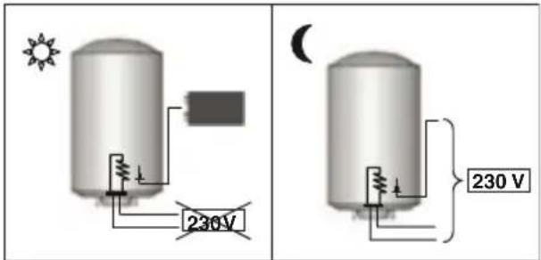
Picture 13 – PROfessional TECH Night-time power supply + batteries
② Permanent power supply
➢ Heating element and PROfessional TECH ⇒ Continuous power supply (Picture 14).
➢ Operation without battery.
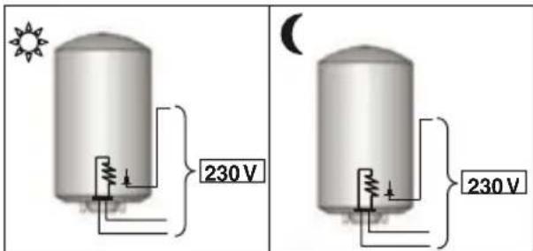
Picture 14 – PROfessional TECH Permanent power supply
IMPORTANT : ONLY FOR WATER HEATER TRI PROFESSIONAL TECH MUST ALWAYS BE SUPPLIED WITH 230V OR 400V AC.
IN CASE OF 400V TRIPHASE NETWORK SUPPLY : PROfessional TECH CONNECTION BETWEEN 2 PHASES 400V.
IN CASE OF 230V TRIPHASE OR 230V MONOPHASE NETWORK SUPPLY : PROFESSIONAL TECH CONNECTION BETWEEN PHASES 230V (Follow electrical wiring described on electrical wiring tag)
OPERATION
1. Introduction
1.1.User considerations
- The installation of the water heater is the responsibility of the purchaser.
- This appliance is not intended for use by persons (including children) with reduced physical, sensory or mental capabilities, or lack of experience and knowledge, unless they have been given supervision or instruction concerning use of the appliance by a person responsible for their safety. Children should be supervised to ensure that they do not play with the appliance.
- The end user is responsible for recycling the appliance once it can no longer be used. For further information, please consult the introduction of this booklet 1.1. – Regulations relating to transportation, storage and recycling.
2. Operating advice
2.1. Temperature adjustment
We recommend the thermostat is not set to its maximum position, in order to avoid limescale build-up and prevent burns. It is nevertheless essential to find a suitable compromise so as to avoid bacterial proliferation while trying to prevent the water heater from experiencing unnecessary limescale build-up.
On the other hand, in order to prevent burns, a suitable mixer should be used so that the temperature does not exceed 50^ C at any of the drawing points. This is a compulsory regulation in France.
Advice When using a mixer at a drawing point, we recommend that the temperature is set to approximately 60^ C.
2.2. Maintenance
➢ Empty the appliance annually (twice a year if the water has been treated with a softening agent) in order to:
- check the condition of the magnesium anode;
- remove all deposits inside the boiler.
Contact your installer.
2.3. Indicator lights
2.3.a. PROfessional TECH steatite range The boiler protection anode is controlled by a P.C.B. powered at the network current or using a battery designed for systems operating in day/night mode, in order to keep the boiler protected during the day. The PROfessional TECH system cannot be left without a power supply for over 48 hours.

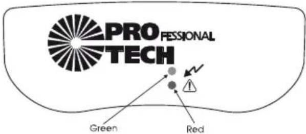
Picture 15 – PROfessional TECH: lights
Green indicator light ON – Red indicator light OFF:
Red indicator light ON: 🤒 Contact your installer.
Green indicator light OFF: 🤒 The boiler is no longer protected against corrosion. Contact the installer.
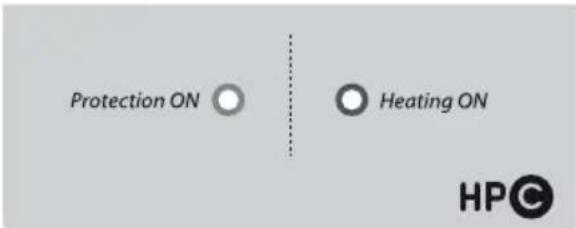
Picture 15a- HPC - QUIE
Green indicator light : light ON or flashing light = 👍
Light OFF = 📋 anti-corrosion protection defect : replace the battery NIMH 9V. If the defect goes on, contact your installer.
Orange indicator light: Light ON= under heating Light OFF = out of heating
If connected to the mains with a dual timer schedule or exclusive night-time schedule (only for models with battery), the green indicator light switches on but is very weak for the first 48 hours in accordance with the charge status of the battery. Check the indication light after 48 hours of operation.
Advice In order to guarantee full boiler protection (green light illuminated), any faulty batteries must be replaced.
If the batteries are not replaced, the guarantee will become void. It makes good sense to replace them once they have been used for one or two years.
MAINTENANCE AND REPAIRS
1. Maintenance
Empty the appliance annually (twice a year if the water has been treated with a softening agent) in order to:
- check the condition of the magnesium anode;
- remove all deposits inside the boiler.
We strongly recommend that the performance of the water softener is checked regularly. The residual hardness cannot be lower than 15^ f. A water hardness level which is too low will cause the guarantee to become void.
1.1. Emptying
➢ Cut off the electricity supply before performing any work on the appliance.
Shut off the cold water supply at the inlet.
➢ Open the hot water tap to draw water.
➢ Open the emptying valve on the safety assembly and the water will flow out of the drainage hole.
1.2. Build-up removal – Checking the anode
➢ Empty the appliance (see above).
➢ Remove the protection element and unscrew the base (some residual water may leak out).
➢ Clean the boiler: without using metal objects or chemical agents, remove any build-up on electrical elements or on the bush (steatite), on the corresponding casing and on the base of the boiler.
If a magnesium anode is used, check its condition: the magnesium anode is consumed progressively in accordance with the water quality, in order to prevent corrosion of the boiler. If the diameter is smaller than 15 mm (for the armoured range) / 10 mm (for the steatite range), or if the total volume is lower than 50% of the initial volume, the anode should be replaced.
➢ Use a new seal every time the base is replaced after being removed.
When screwing in the bolts again, use a "cross-tightening" technique. The tightening torque should be between 7 and 10 Nm.
2. Problems, causes and solutions
The problems which occur most frequently are listed below. The various causes and suggested courses of action are also provided.
| PROBLEM | Cold water | Water is too hot | Insufficient flow rate | Continuous drainage from the safety assembly | Green light switched off (PROfessional TECH stealte range) - HPC-QUIE | Red light illuminated (PROfessional TECH stealte range) | Rusty-coloured water | Water has an unpleasant odour | Water leakage | Water heater is warped | Noise caused by water heater | POSSIBLE CAUSES COURSE OF ACTION |
| CAUSES AND SOLUTIONS | Power cut (during heating phase)Check the fuses and replace them if necessary | |||||||||||
| Incorrect temperature adjustment using thermostatAdjust the thermostat (+ to the right; - to the left) | ||||||||||||
| Electronic thermostat overheating safety activated (appliance overheated)See1 | ||||||||||||
| Faulty heating elementsSee2 | ||||||||||||
| Unsuitable day-night programmingWhere necessary, re-activate the heating during the day | ||||||||||||
| Thermostat malfunctionSee1 | ||||||||||||
| Limescale build-up inside appliance and/or safety assemblyRemove build-up If necessary replace the safety assembly | ||||||||||||
| Water mains pressureCheck the mains pressure. If necessary, install a pressure reducer. | ||||||||||||
| Water mains flow rate Check the piping | ||||||||||||
| Faulty baffle or insertContact the technical assistance centre | ||||||||||||
| Removal of build-up from the safety assemblyReplace the safety assembly | ||||||||||||
| PROfessional TECH circuit malfunctioningSee3 | ||||||||||||
| Batteries exhausted or not charged sufficientlySee4 | ||||||||||||
| No mains power in the PROfessional TECH circuitMake sure the circuit is supplied with power | ||||||||||||
| Boiler empty Fill the boiler | ||||||||||||
| Fast coupling connector not connectedConnect the fast coupling connector | ||||||||||||
| Electrode circuit broken Check the circuit | ||||||||||||
| Condition of cables from electronic circuit connectorCheck the cables | ||||||||||||
| Electrode connector earthing Check the wiring | ||||||||||||
| Appliance capacity insufficient for requirements | ||||||||||||
| Water heater corrosionEmpty the water heater and make sure there is no internal corrosion. If there is, replace the water heater | ||||||||||||
| Bacteria developmentEmpty and clean the appliance and replace the anode if using a model with a magnesium anode | ||||||||||||
| Base seal malfunctionReplace the seal (the seal must be replaced every time the base is removed!) |
① Replacing or resetting the thermostat
If the thermostat is deactivated, reset it and establish the cause (short-circuit, faulty thermostat, etc.).
CAUTION: Every thermostat is designed to be reset a maximum of two or three times only!
② Replacing the heating element
Check the Ohmic value of the heating element and, if necessary, replace it. A null or an infinite value indicates that the heating element must be replaced.
Armoured range
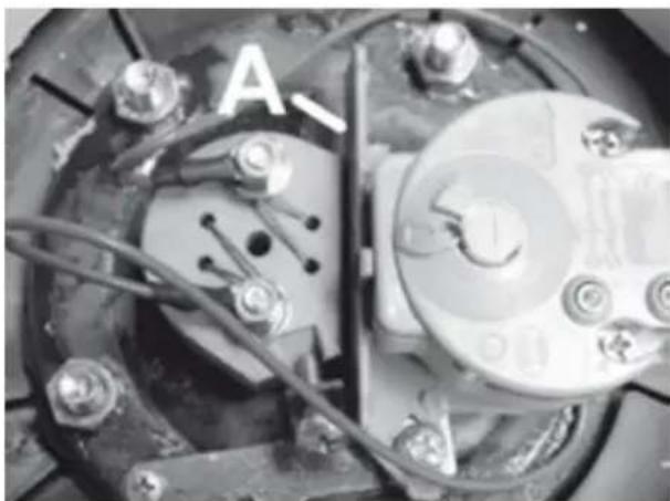
The appliance must be emptied before the armoured heating element may be replaced. Steatite range – PROfessional TECH steatite range
It is not necessary to empty the appliance before replacing the heating element. During a Technical Assistance procedure for a steatite water heater, it is absolutely necessary to replace the plastic separator between the thermostat and the heating element in the water heater as this guarantees the correct operation of the appliance.
natural_image
Close-up of mechanical components with visible wiring and bolts (no text or symbols)Picture 17 - Plastic separator / A: plastic separator
③ Replacing the electronic circuit
PROfessional TECH PTEC steatite range
Before performing any work, make sure you have isolated the appliance from the electricity supply network. The replacement of the electronic circuit is a very simple process. After removing the plastic protection:
➢ Disconnect the storage cell (press-fit connector on the storage cell).
➢ Disconnect the 2 wires running from the electronic circuit to the power supply terminal board.
➢ Disconnect the fast coupling connector with the false movement protection device which links the circuit to the boiler and the electrode.
➢ Disconnect the electronic circuit from the support (plastic material clips on the corners).
➢ Replace the faulty circuit with a new one.
Repeat the procedure described above in the reverse order.
④ Replace the battery.
PROfessional TECH steatite range - HPC
The storage cell is replaced by disconnecting the press-fit connector and replacing the old storage cell with a new rechargeable one, Ni-Mh 9 volt 150 mAh minimum.
GUARANTEE CONDITIONS
Preface: The following provisions cannot be used to reduce or cancel the statutory claim against hidden defects (art. 1611 and subsequent modification of the Civil code).
Given the technical nature of the product and in order to guarantee the safety and protection of the consumer, the electric water heater must be installed, prepared for operation and regularly serviced by a qualified professional in accordance with the instructions provided in the installation manual and in full compliance with industry standards. The appliance must be used in a normal manner, in compliance with industry standards and in accordance with current legislation and the instructions supplied in the installation manual.
The product is developed and guaranteed for the installation and use in domestic appliances.
For industrial use or non domestic ones, take contact with the manufacturer to insure the guarantee and good working of the product.
Given the technical nature of the product, repairs under guarantee must be performed by an authorised technician. The manufacturer shall not be held liable for repairs performed and parts supplied by other professionals or their authorised technicians.
Breakdowns due to the following conditions are not covered by the guarantee:
Unusual environmental conditions:
➢ Positioning the appliance in a place which is subject to ice or bad weather.
Supplying the appliance with rainwater, well water or water which contains an unusually aggressive content and which does therefore not conform to national regulations or current legislation.
The hardness of the running water must be greater than 12^ f.
The use of a softener does not affect our guarantee, on the condition that the softener is correctly calibrated, monitored and subject to regular maintenance. In this case, the residual hardness must be greater than 15^ f.
Water pressure greater than 4.5 bar.
- Various damages caused by knocks or falls during handling after the appliance has been delivered.
In particular, water damage which could have been prevented if the water heater had been repaired immediately. The guarantee only applies to the water heater and its components, with the exception of all or part of the electrical or hydraulic system of the appliance.
➢ Electricity supply with significant amounts of excess voltage.
A system which does not comply with regulations, current national legislation and which is unprofessional, in particular:
The absence or incorrect installation of the safety assembly.
The installation of a safety assembly which does not conform to current national legislation of the use of a worn-out safety assembly inside a newly-installed water heater.
➢ Modification of the safety assembly adjustment after irregular plumbing work.
The use of a tripod which has not been authorised by the manufacturer, or which has not been installed
according to the instructions given in this manual.
➢ Unusual corrosion due to poor hydraulic connections (direct iron-copper contact); a lack of insulating attachments.
Faulty electrical connection which does not conform to national installation regulations, poor earthing, insufficient wire cross-section, non-adherence to supplied connection diagrams, etc.
Switching the appliance on without filling it up first (dry heating).
➢ Installation without retention tank as recommended in paragraph 1.1.
➢ Appliance installed in a narrow room with inaccessible electrical parts.
The use of spare parts which have not been authorised by the manufacturer.
Insufficient maintenance: the water heater must undergo annual maintenance:
➢ Unusual build-up on the heating elements and the safety devices.
A lack of maintenance in terms of the safety assembly, with resulting excessive pressure.
Bodywork subjected to external violence.
Modification of the original systems without the manufacturer's approval or using spare parts which have not been specified by the manufacturer.
A lack of maintenance in terms of the appliance itself, especially regarding the replacement of the anode when necessary.
No replacement of the batteries in an appliance which uses them, or replacement of rechargeable batteries with batteries which do not conform to the demands listed in this set of instructions.
The guarantee is limited to the replacement or repair of appliances and components which we recognise as being originally faulty. If necessary, the part or product should be returned to one of our factories, only after an agreement is made with our Technical Assistance Centres. All expenses relating to labour, carriage, packaging and handling will be paid for by the user. The replacement or repair of a component inside an appliance may not, in any event, give rise to compensation.
Certificate n. TC-B.60719 valid from 21/11/2013 until 20/11/2016
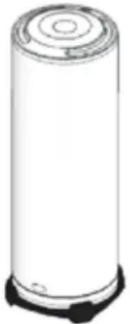
natural_image
White cylindrical water heater with a small black outlet, shown against a plain background (no text or symbols visible)عزيزي العميل،
مقدمة
ال fenج Introduction.1
natural_image
3D rendered mechanical component with bolts and a nut, no text or symbols visibleالصمام
natural_image
Close-up of a mechanical component with bolts and wiring (no visible text or symbols)88 48 333/02 : الهاتف
89 333.48/02 : فاكس

- INTRODUCTION 9
- PRÉSENTATION DU PRODUIT 9
- PROfessional TECH - HPC - QUIE
- Incidents, causes et actions
- PROfessional Tech (PTEC) - HPC - QUIE
- • CAUTION: the appliance MUST be earthed!
- INTRODUCTION 48
- INTRODUCTION TO THE PRODUCT 48
- INSTALLATION 49
- LEGAL OBLIGATIONS AND RECOMMENDATIONS RELATING TO PRODUCT INSTALLATION DEFINITION AUTHORISED FIXING AREAS FOR THE WATER HEATER 49
- INSTALLING THE PRODUCT 50
- ELECTRICAL CONNECTION 52
- OPERATION 53
- MAINTENANCE AND REPAIRS 54
- MAINTENANCE 54
- GUARANTEE CONDITIONS 57
- INTRODUCTION
- Introduction to the product
- Regulations relating to transportation, storage and recycling
- GB
- Dimensions
- THER armoured range
- STEA steatite range
- PROfessional TECH PTEC steatite range - HPC - QUIE
- 1.5.a. Definition of the range
- INSTALLATION
- Legal obligations and recommendations relating to product installation
- Recommendation when installing in the bathroom:
- Installing the product
- Material required
- If the water heater is fitted with fixing brackets:
- 2.1.b. Accessories
- Indispensable accessories:
- Others:
- Assembly
- 2.2.b. VERT Vertical wall-fitted model
- 2.2.c. HORD horizontal model
- HORDroit version with water inlet and outlet pipes on the protection element
- HORBas HORB version with water inlet and outlet pipes on the bodywork ring nut
- 2.2.d. STAB models on base structures
- Water connection
- Electrical connection
- Important considerations
- THE WIRING DIAGRAM IS STUK ONTO THE APPLIANCE: USE IT AS A REFERENCE GUIDE.
- VERT, HORD, HORB three-phase vertical model, MT version
- STAB MT stable model
- ANY DIRECT CONNECTION TO THE HEATING ELEMENT IS HAZARDOUS ANS IS STRICTLY PROHIBITED.
- PROfessional TECH (PTEC) and HPC - QUIE
- CAUTION:
- OPERATION
- Introduction
- 1.1.User considerations
- Operating advice
- Temperature adjustment
- Maintenance
- Indicator lights
- MAINTENANCE AND REPAIRS
- Maintenance
- Emptying
- Build-up removal – Checking the anode
- Problems, causes and solutions
- ① Replacing or resetting the thermostat
- ② Replacing the heating element
- Armoured range
- ③ Replacing the electronic circuit
- PROfessional TECH PTEC steatite range
- ④ Replace the battery.
- PROfessional TECH steatite range - HPC
- GUARANTEE CONDITIONS
- Unusual environmental conditions:
Brand : Ariston Thermo
Model : THERserie
Category : Boiler