GDU 60651 - Dishwasher MIELE - Free user manual and instructions
Find the device manual for free GDU 60651 MIELE in PDF.
User questions about GDU 60651 MIELE
0 question about this device. Answer the ones you know or ask your own.
Ask a new question about this device
Download the instructions for your Dishwasher in PDF format for free! Find your manual GDU 60651 - MIELE and take your electronic device back in hand. On this page are published all the documents necessary for the use of your device. GDU 60651 by MIELE.
USER MANUAL GDU 60651 MIELE
GB Installation instructions
text_image
Diagram illustrating a door handle mechanism with numbered arrows indicating movement and direction of motion, labeled ①, ②, and ③.natural_image
Diagram of a cabinet or storage unit with an X-axis indicator and directional arrows (no text or symbols)natural_image
Illustration of a hand inserting a pencil into a refrigerator with a downward arrow indicating the process (no text or symbols present)natural_image
Technical line drawing of a cabinet with an open door and a paper holder containing a large upward arrow (no text or symbols)text_image
Diagram illustrating a mechanical assembly with labeled components and directional arrows, showing motion paths and component placement.natural_image
Technical diagram of a mechanical assembly with circular components and mounting holes (no text or labels)text_image
Technical diagram showing installation of a door panel with screw fasteners and mounting holes, including magnified views of the component.natural_image
Diagram of a mechanical assembly with a bracket and gear mechanism, showing no text or symbolsnatural_image
Diagram of a mechanical assembly with arrows indicating movement or force, showing a bolt and bracket (no text or symbols present)natural_image
Diagram of a rectangular panel with internal components and upward arrows indicating flow or movement (no text or symbols)natural_image
Diagram of a mechanical assembly with two blocks and directional arrows indicating movement or force (no text or symbols)natural_image
Technical diagram of a mechanical assembly with no visible text or symbolsnatural_image
Technical diagram of a mechanical assembly with a magnified inset showing a bracket component (no text or symbols present)text_image
Diagram illustrating a door lock mechanism with numbered arrows indicating sequence and direction of movementnatural_image
Diagram of a cabinet or storage unit with an X-axis indicator and directional arrows, no text or symbols present.natural_image
Illustration of a hand inserting a tool into a door panel with a downward arrow indicating direction (no text or symbols)natural_image
Diagram of a cabinet with an open door and a paper holder containing a large upward arrow (no text or symbols present)text_image
Diagram illustrating a mechanical device's operation with labeled components and directional arrows indicating rotation and adjustment.natural_image
Technical diagram of a mechanical assembly with circular components and mounting holes (no text or symbols)text_image
Technical diagram showing screw installation steps with magnified views of the componentnatural_image
Diagram showing a mechanical assembly with a sliding door and gear mechanism, no text or symbols presentnatural_image
Mechanical assembly diagram showing a bolt inserted into a component with a sliding mechanism (no text or symbols)natural_image
Diagram of a rectangular panel with internal components and upward arrows indicating flow or movement (no text or symbols)natural_image
Diagram of a mechanical assembly with directional arrows indicating movement or force (no text or symbols present)natural_image
Technical diagram of a mechanical assembly with no visible text or symbolsnatural_image
Technical diagram showing a mechanical assembly with a magnified inset of a bracket component (no text or symbols present)These instructions describe all the steps necessary for fitting the GDU decor set.
They should be read in conjunction with the Dishwasher installation diagram which has detailed instructions on installation and fitting.
GDU decor set for building-under a dishwasher
By using a GDU decor set, an integrated (i) model dishwasher can be converted into a built-under (U) model dishwasher.
The GDU decor set consists of:
- a front panel with inset decor panel,
- a plinth facing with fixing brackets.
GDU 45/60-1 and GDU 60/60-1:
These decor sets are designed for use in kitchens with 720 mm high base units (lower edge of the worktop to the lower edge of the kitchen cabinet door).
GDU 65/65-1 (XXL dishwashers):
These decor sets are designed for use in kitchens with 770 mm high base units (lower edge of the worktop to the lower edge of the kitchen cabinet door).
The decor panel supplied with the GDU set can be replaced by a panel to match your kitchen cabinetry.
1. Fitting the protective cover plate and fascia panel
Fit the protective cover plate and fascia panel as described in the "Installation diagram for built-in dishwashers".
Make sure that you keep all dishwasher accessories and spacer strips that are not necessary for fitting the GDU decor set in a safe place for future use. These will be required if you want to convert the dishwasher back to an integrated model, e.g. if you buy a new kitchen.
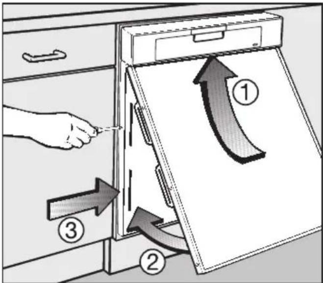
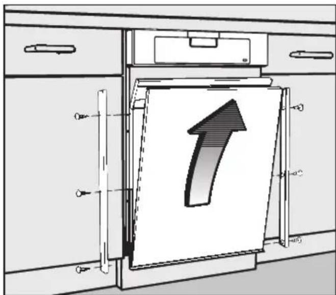
2.Fitting the front panel
text_image
Diagram illustrating a door handle mechanism with numbered arrows indicating movement and direction of motion, labeled ①, ②, and ③.■ Push the front panel up at an angle under the fascia panel ① and then into the slots on the door front outer panel ②.
Make sure that the top edge of the front panel slides up and fits neatly in place under the fascia panel.
■ Tighten the TORX T20 screws ③ located on either side of the door front outer panel.
■ Use the plastic stoppers supplied to blank off the openings in the fixing mechanism.
3. Aligning the dishwasher
Push the dishwasher into the recess and align it as described on the "Installation diagram for built-in dishwashers".
If you want to build the dishwasher into a corner you must first attach the fixing plate to the appropriate side of the dishwasher (see "Installation diagram for built-in dishwashers").
If you are using the decor panel supplied and the lower edge aligns with the lower edge of the neighbouring kitchen cabinets you can miss out steps 4 and 5 and continue from step 6.
4.Calculating the decor panel height
To calculate dimension "X".
■ Measure the distance from the bottom of the adjoining kitchen cabinet door to the lower edge of the dishwasher door.

natural_image
Diagram of a cabinet or storage unit with an X-axis indicator and directional arrows, no text or symbols present.Decor panel factory dimensions:
For 60 cm wide dishwashers: H 605 x W 585 mm
For 45 cm wide dishwashers: H 605 x W 435 mm
XXL dishwashers:
60 cm wide XXL models H 655 x W 585 mm
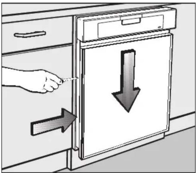
5. Replacing the front panel
■ Pull the dishwasher out of its recess enough to allow easy access to the front panel fixing screws on either side of the door.
natural_image
Illustration of a hand inserting a pencil into a cabinet with a downward arrow indicating the process (no text or symbols present)■ Loosen the TORX T20 screws on either side of the door front outer panel, just until you are able to lower the front panel.
natural_image
Technical line drawing of a cabinet with an open door and a paper holder containing a 3D arrow symbol (no text or labels present)■ Unscrew and remove the decor strips (use a PZ No. 2 cross-head screwdriver).
■ Remove the decor strips, decor panel, filler card and polystyrene spacers.
⚠️ Use masking tape along the cutting line to protect the panel and strips from damage during cutting. Use a cutting tool suitable for the material. If in doubt contact a qualified fitter.
When using the decor panel supplied:
■ Shorten the decor strips, decor panel, filler card and polystyrene spacers from the top by dimension X (as previously calculated).
When using a new decor panel:
If you are using a decor panel which matches your kitchen units, cut it to the following size:
60 cm wide dishwashers:
Height = 605 mm minus
Dimension X (as previously calculated)
Width = 585 mm
45 cm wide dishwashers:
Height = 605 mm minus
Dimension X (as previously calculated)
Width = 435 mm
XXL dishwashers:
60 cm wide XXL models:
Height = 655 mm minus
Dimension X (as previously calculated)
Width = 585 mm
If the new decor panel is thicker than 2 mm (max. 4 mm), remove the filler card from the front panel.
■ Shorten the decor strips, polystyrene spacers and if necessary, the filler card from the top by dimension X (as previously calculated).
For all the above cases:
■ Reassemble the front panel and fit to the dishwasher as described in step 2.
■ Push the dishwasher right back into its recess and make sure it is aligned correctly. Proceed to step 6.
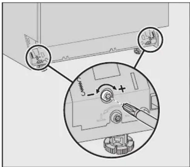
6. Adjusting the door springs
The door springs are correctly adjusted when a half opened door (approx. 45° opening angle) remains in that position when released.
If the door drops down, the door springs need to be tightened.
If the door rises up the springs need to be loosened.
The adjusting screws are located on the front right-hand and front left-hand side of the dishwasher plinth.
text_image
Diagram showing mechanical assembly steps with labeled components and directional arrows indicating motion or movement.- Adjust the door spring with a TORX T20 or a 1 x 5.5 mm screwdriver until it is correctly balanced: - turn clockwise to tighten - turn anti-clockwise to loosen.
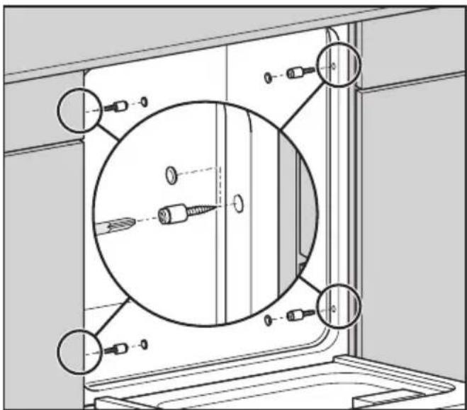
7.Securing the dishwasher
Building-in between two kitchen units
To ensure stability, the dishwasher must be screwed to the adjoining kitchen units on either side after it has been positioned and aligned.
■ Open the dishwasher door.
natural_image
Technical diagram of a mechanical assembly with circular components and mounting holes (no text or symbols)- Secure the dishwasher to the kitchen units on the right and left hand side with the 4 x 25 screws supplied using a TORX T20 screwdriver.
Do not use a cordless screwdriver to secure the dishwasher to the adjoining units. Do not remove the plastic sleeves from the screws.
■ Plug the openings with the plastic stoppers supplied.
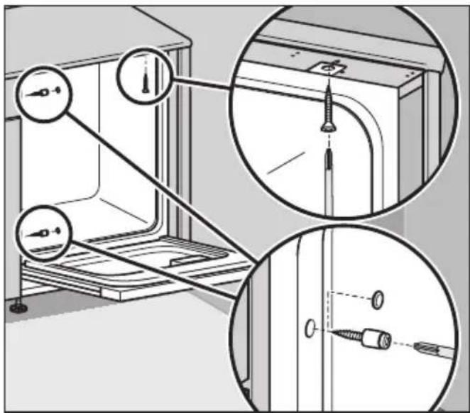
Building into a corner
If you are building the dishwasher into a corner you will only be able to secure the dishwasher to an adjoining unit on one side. The side which is against the wall must be secured to the worktop above it.
■ Open the dishwasher door.
The hole in the fixing plate must line up with the long hole in the protective cover plate under the worktop as shown.
text_image
Technical diagram showing installation of a door panel with screw fasteners and mounting holes, including close-up views of the component.- Secure the dishwasher to the worktop from below with the 4 x 22 countersunk screws supplied using a TORX T20 screwdriver.
■ Secure the dishwasher to the adjoining kitchen unit on the other side with the 4 x 25 screws supplied using a TORX T20 screwdriver.
Do not use a cordless screwdriver to secure the dishwasher to the neighbouring units. Do not remove the plastic sleeves from the screws.
■ Plug the openings with the plastic stoppers supplied.
Ensure that the seal on the top edge of the dishwasher fits directly against the worktop. If this is not the case, adjust the feet a bit more.
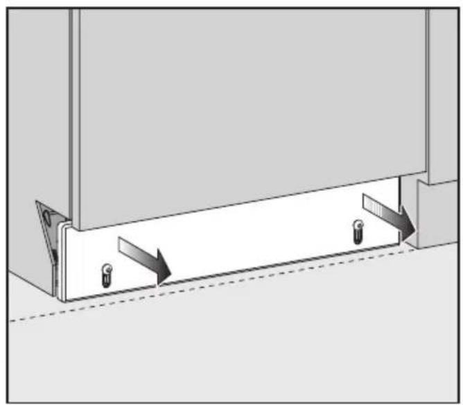
8.Fitting a plinth facing
If the dishwasher is installed in a kitchen with a continuous kitchen plinth facing the next step will not be necessary.
Follow the instructions given in the Dishwasher installation diagram for aligning an integrated dishwasher plinth fascia.
The plinth facing supplied will fit without modification when:
- the plinth recess is at its maximum depth of 100 ~mm , and
- the machine is set to its maximum height (feet fully extended to 6 cm).
If the machine height is lower than the maximum, and the plinth recess is less than 100 mm, the plinth facing will need to be trimmed to size (to ensure that the door and plinth facing do not touch when the door is opened). To calculate the required height of the plinth facing:
■ On either side, push the spring clips to the side and push the brackets right in.
If the feet are only slightly extended:
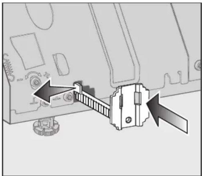
natural_image
Diagram of a computer monitor with a door and gear assembly, showing no text or symbolsThe fixing brackets face upwards.
If the feet are more fully extended:
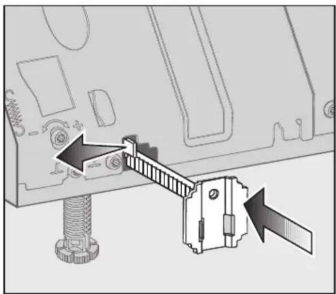
natural_image
Diagram of a mechanical assembly with arrows indicating force or movement, showing a bolted joint and sliding mechanism (no text or symbols present)The fixing brackets face downwards.
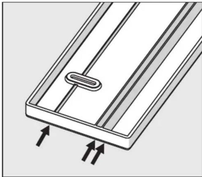
natural_image
Diagram of a rectangular panel with internal components and upward arrows indicating flow or movement (no text or symbols)The plinth facing has three cutting lines.
natural_image
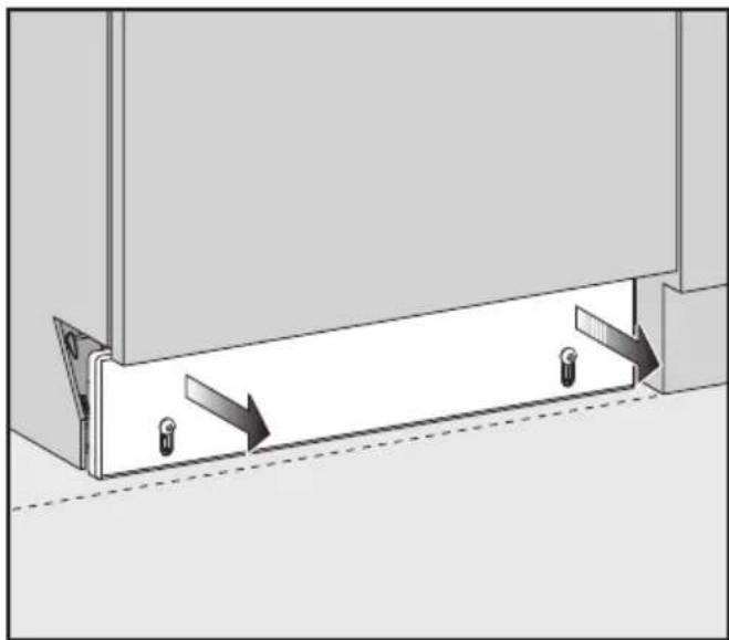
Diagram of a mechanical assembly with two arrows indicating direction, no text or symbols present■ Screw the plinth facing on to the brackets with the cutting lines towards the top (4x16 / TORX T20). Then pull the facing out evenly to align it with plinth facings on adjoining kitchen cabinets.
If you have pulled the plinth facing out too far you must not attempt to push it back in. It will have to be unscrewed and taken off. The spring clips can then be pushed outwards and the brackets pushed back in. The facing can then be re-attached and adjusted again.
natural_image
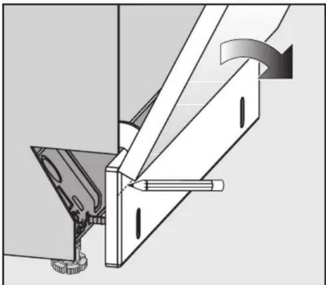
Mechanical assembly diagram showing a lever mechanism with a tool and rotating component (no text or symbols)■ Carefully open the dishwasher door until the lower edge of the dishwasher door abuts the plinth facing (see illustration).
■ Using the front lower edge of the dishwasher door as a guide, draw a horizontal line across the plinth facing.
■ Unscrew the plinth facing.
■ To shorten the plinth facing:
– either trim along this line with a saw;
or
– cut along one of the cutting lines if it is close enough to the line you have drawn.
Score the cutting line along the plinth facing and then break off the excess.
■ Screw the plinth facing back onto the brackets, with the cutting line at the top.
If the door still does not open smoothly the plinth facing may need further trimming.
Please refer to the Dishwasher installation diagram and the operating instructions before connecting the dishwasher to the electricity supply.
text_image
Diagram illustrating a door lock mechanism with numbered arrows indicating sequence and direction of movementnatural_image
Diagram of a cabinet or storage unit with an X-axis indicator and directional arrows (no text or symbols)natural_image
Illustration of a hand inserting a device into a cabinet with a downward arrow indicating internal movement (no text or symbols)natural_image
Technical line drawing of a cabinet with an open door and a paper holder, featuring a large upward arrow symbol (no text or labels present)text_image
Diagram illustrating a mechanical assembly process with labeled components and directional arrows indicating motion or movement.natural_image
Technical diagram of a mechanical assembly with circular components and mounting holes (no text or symbols)text_image
Technical diagram showing a door assembly with close-up insets of screw fasteners and temperature readings.natural_image
Diagram showing a mechanical assembly with a bracket and gear mechanism, no text or symbols presentnatural_image
Diagram showing mechanical assembly with a lever and base component, no text or symbols presentnatural_image
Diagram of a rectangular panel with internal components and upward arrows indicating flow or movement (no text or symbols)natural_image
Diagram of a mechanical assembly with two vertical supports and directional arrows indicating motion (no text or symbols)natural_image
Mechanical assembly diagram showing a lever mechanism with a tool and gear (no text or symbols)text_image
Diagram illustrating a door handle mechanism with numbered arrows indicating movement and direction of motion, labeled ①, ②, and ③.natural_image
Diagram of a cabinet or storage unit with an X-axis indicator and directional arrows, no text or symbols present.natural_image
Illustration of a hand inserting a small object into a cabinet with a downward arrow indicating process (no text or symbols)natural_image
Diagram of a cabinet with an open door and a paper holder containing a large upward arrow (no text or symbols present)text_image
Technical diagram showing mechanical assembly with labeled components and a magnified view of the component's rotation direction.natural_image
Technical diagram of a mechanical assembly with circular components and mounting holes (no text or labels)text_image
Technical diagram showing assembly of a door panel with screw holes and a screwdriver, including magnified views of the component.natural_image
Diagram showing a mechanical assembly with a sliding door and gear mechanism, no text or symbols presentBeslagene peger opad.
natural_image
Mechanical assembly diagram showing a bolt inserted into a component with a sliding mechanism (no text or symbols)natural_image
Diagram of a rectangular panel with internal components and upward arrows indicating flow or movement (no text or symbols)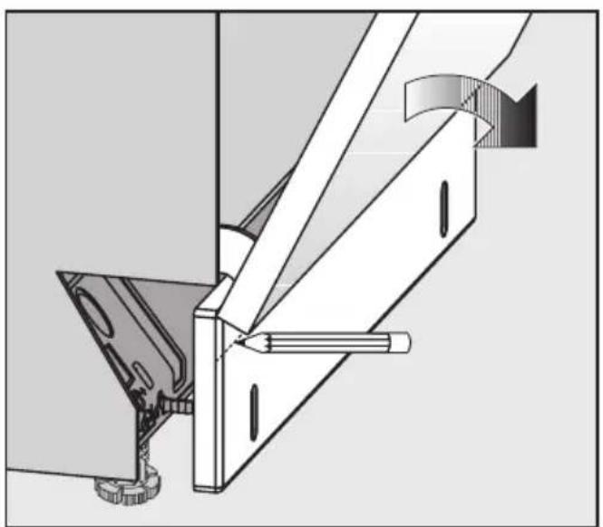
natural_image
Technical diagram of a mechanical assembly with no visible text or symbols