
HWL-C21A - WLAN module Hanwha - Free user manual and instructions
Find the device manual for free HWL-C21A Hanwha in PDF.
| Product Type | WLAN Module |
| Brand | Hanwha |
| Model | HWL-C21A |
| Standards | Compliant with Industry Canada RSS (RSS-Gen) |
| IC Certification Number | 32218-WLC21SSAK00 |
| Frequency Band | 2,4 GHz (WLAN) |
| Power Supply | Provided by host (typ. 3.3 V DC) |
| Approx. Dimensions | 25 x 20 x 5 mm |
| Approx. Weight | 10 g |
| Operating Temperature | -20 °C to +70 °C |
| Operating Humidity | 5 % to 90 % (non-condensing) |
| RF Safety Distance | At least 20 cm between antenna and any person |
| Installation | Only in battery-powered vehicles |
| Power Supply | The host must provide a stable voltage (tested between 85% and 115% of nominal voltage) |
| Final Product Labeling | Must mention: "Contains transmitter module IC: 32218-WLC21SSAK00" |
| Maintenance | Clean with a dry, soft cloth |
| Cleaning | Do not use solvents or abrasive products |
| Safety | Avoid prolonged exposure near the antenna |
| Spare Parts | Not available separately |
| Repairability | No user-serviceable parts |
| Intended Use | Integration into a host product for WLAN connectivity |
Frequently Asked Questions - HWL-C21A Hanwha
User questions about HWL-C21A Hanwha
0 question about this device. Answer the ones you know or ask your own.
Ask a new question about this device
Download the instructions for your WLAN module in PDF format for free! Find your manual HWL-C21A - Hanwha and take your electronic device back in hand. On this page are published all the documents necessary for the use of your device. HWL-C21A by Hanwha.
USER MANUAL HWL-C21A Hanwha
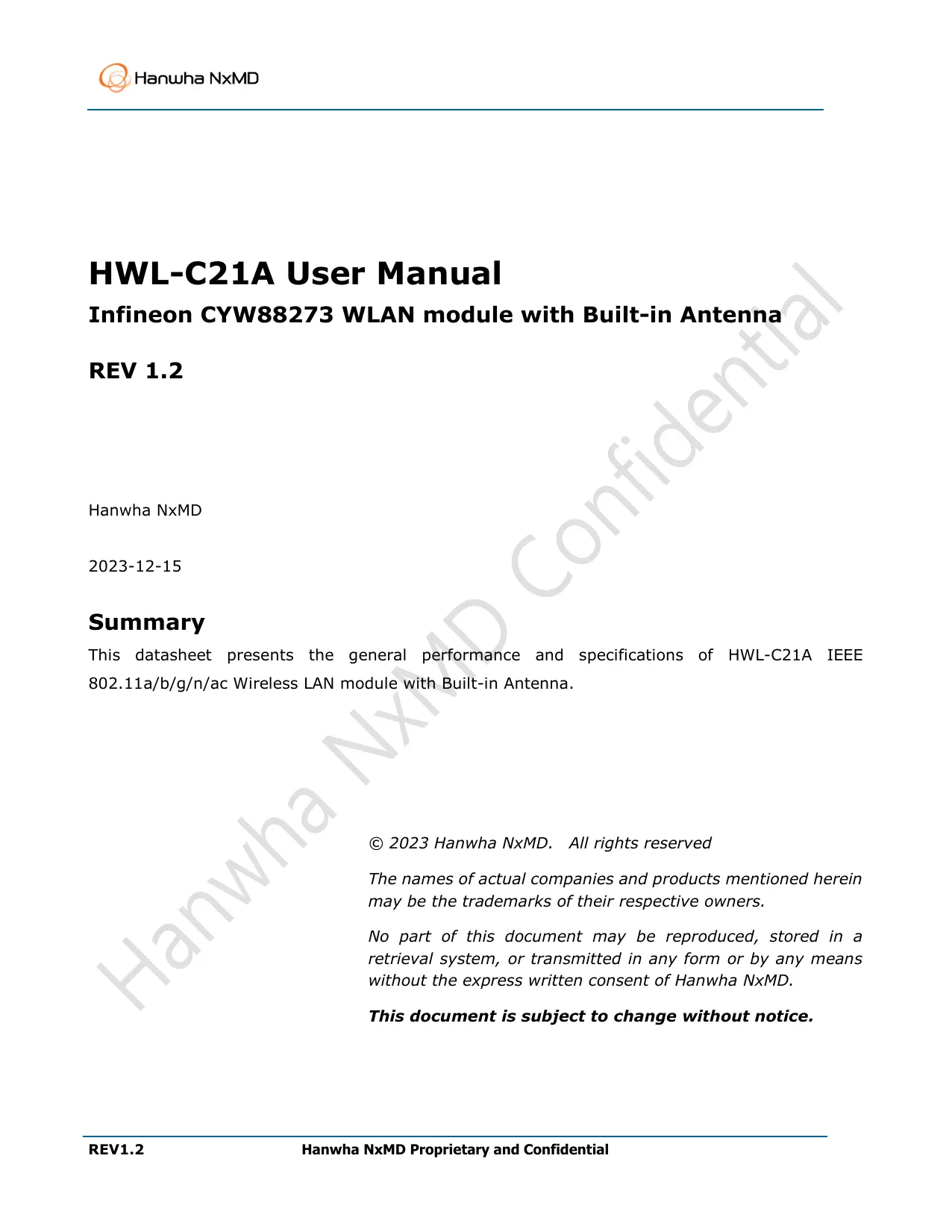
HWL-C21A User Manual
Infineon CYW88273 WLAN module with Built-in Antenna
REV 1.2
Hanwha NxMD
2023-12-15
Summary
This datasheet presents the general performance and specifications of HWL-C21A IEEE 802.11a/b/g/n/ac Wireless LAN module with Built-in Antenna.
© 2023 Hanwha NxMD. All rights reserved
The names of actual companies and products mentioned herein may be the trademarks of their respective owners.
No part of this document may be reproduced, stored in a retrieval system, or transmitted in any form or by any means without the express written consent of Hanwha NxMD.
This document is subject to change without notice.
1 General Description
1.1 Functional Description
HWL-C21A Module provides the highest level of integration for Automotive and IoT systems with integrated Dual-band IEEE 802.11ac WLAN MAC/baseband/radio MAC/baseband/radio, and integrated Power Management Unit.
WLAN interfaces to host processor through a PCIe v3.0 Gen1 or SDIO 3.0 interface.
HWL-C21A is based on Infineon CYW88273 solution. CYW88273 is qualified to operate across
Automotive Grade 3 (-40°C to +85°C) temperature range. It is also AEC Q-100 tested and manufactured in ISO9001/IATF16949 certified fabrication facilities.
1.2 Features
WLAN
- IEEE 802.11ac compliant
● Support for MCS8 VHT20 in 20 MHz channels for up to 86.7 Mbps
● Supports 20, 40, and 80MHz channels with optional SGI (256QAM modulation)
● Full IEEE 802.11a/b/g/n legacy compatibility with enhanced performance
Interfaces
- PCIe mode complies with PCI Express base specification revision 3.0 for x1 lane and power management running at Gen1 speed(Option)
● Supports standard SDIO v3.0 host interface. Backward compatible with SDIO v2.0 host interface
General
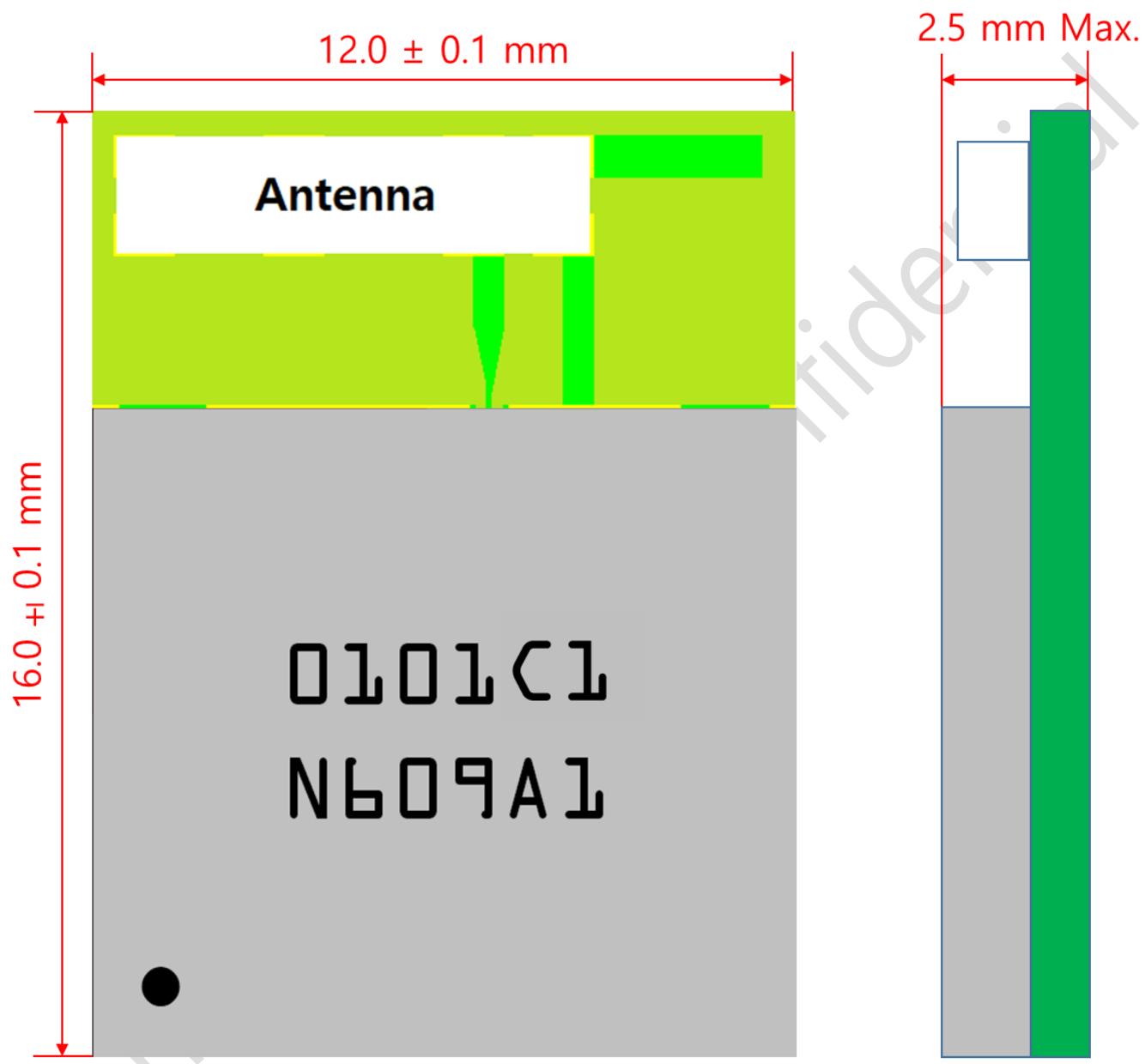
- Compact dimension: 16.0±0.10 x 12.0±0.10 mm / Height : 2.50 mm max.
- RoHS compliant
1.3 Applications
- Automotive
● High-performance Infotainment and Telematics
2 Dimension and Pin Assignments
2.1 Mechanical Dimension
other
| Component | Thickness (mm) | | --------------- | -------------- | | Antenna | 12.0 ± 0.1 | | N609A1 | 16.0 ± 0.1 | | Total Width | 2.5 mm Max. |Figure 2-1 HWL-C21A Mechanical Dimension (Top & Side view)
other
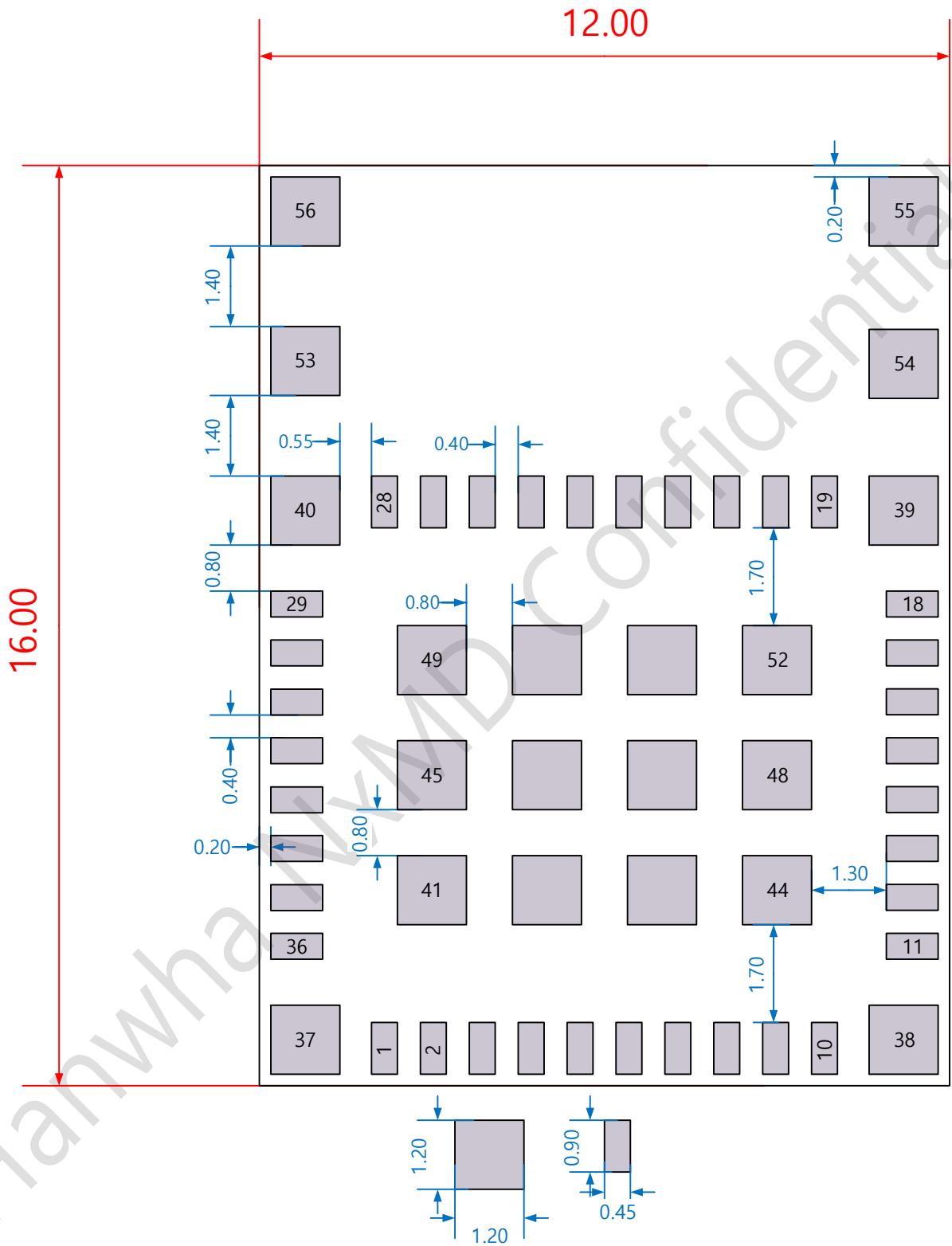
| Row | Column | Value | |---|---|---| | 1 | 56 | 0.20 | | 1 | 55 | 0.20 | | 1 | 53 | 0.40 | | 1 | 40 | 0.55 | | 1 | 29 | 0.80 | | 1 | 49 | 0.80 | | 1 | 45 | 1.70 | | 1 | 41 | 1.70 | | 1 | 36 | 1.70 | | 1 | 37 | 1.70 | | 2 | 52 | 1.30 | | 2 | 48 | 1.30 | | 2 | 44 | 1.30 | | 2 | 38 | 1.30 | | 2 | 36 | 1.30 | | 2 | 37 | 1.30 | | 3 | 54 | 0.45 | | 3 | 55 | 0.45 | | 3 | 40 | 0.40 | | 3 | 28 | 0.40 | | 3 | 19 | 0.40 | | 3 | 39 | 0.40 | | 3 | 29 | 0.80 | | 3 | 49 | 0.80 | | 3 | 45 | 0.80 | | 3 | 41 | 0.80 | | 3 | 36 | 0.80 | | 3 | 37 | 0.80 | | 4 | 52 | 1.70 | | 4 | 54 | 1.70 | | 4 | 48 | 1.70 | | 4 | 44 | 1.70 | | 4 | 39 | 1.70 | | 4 | 36 | 1.70 | | 4 | 37 | 1.70 | | 5 | 52 | 1.70 | | 5 | 54 | 1.70 | | 5 | 48 | 1.70 | | 5 | 44 | 1.70 | | 5 | 39 | 1.70 | | 5 | 36 | 1.70 | | 5 | 37 | 1.70 | | ... (additional values not labeled) are not explicitly provided in the image.)Figure 2-2 HWL-C21A Bottom Pad Dimension (Top View)
2.2 Pin Assignments
| Pin No. | Pin Description | Pin No. | Pin Description | Pin No. | Pin Description |
| 1 | PCIE_CLK_N | 21 | GND | 41 | GND |
| 2 | PCIE_CLK_P | 22 | GND | 42 | GND |
| 3 | GND | 23 | NC | 43 | GND |
| 4 | PCIE_TD_N | 24 | GND | 44 | GND |
| 5 | PCIE_TD_P | 25 | GND | 45 | GND |
| 6 | GND | 26 | PCIE_PME_L | 46 | GND |
| 7 | PCIE_RD_N | 27 | PCIE_RST_L | 47 | GND |
| 8 | PCIE_RD_P | 28 | PCIE_CLK_REQ_L | 48 | GND |
| 9 | GND | 29 | GND | 49 | GND |
| 10 | VBAT | 30 | GND | 50 | GND |
| 11 | NC | 31 | SDIO_CMD | 51 | GND |
| 12 | NC | 32 | SDIO_DATA_1 | 52 | GND |
| 13 | WL_REG_ON | 33 | SDIO_DATA_2 | 53 | NC |
| 14 | GND | 34 | SDIO_DATA_0 | 54 | NC |
| 15 | VIO | 35 | SDIO_CLK | 55 | NC |
| 16 | GND | 36 | SDIO_DATA_3 | 56 | NC |
| 17 | STRAP_1 | 37 | GND | ||
| 18 | STRAP_0 | 38 | GND | ||
| 19 | GND | 39 | GND | ||
| 20 | LPO_IN | 40 | GND |
Figure 2-3 HWL-C21A Pin Assignments
3 Pin Descriptions
Table 3-1 Pin Descriptions
| Pin# | Signal Name | Type | Connection to IC Pin | Power Domain | Description |
| WLAN PCI Express Interface | |||||
| 27 | PCIE_RST_L | I(PU) | PERST_L | - | PCIE System Reset. This input is the PCIE reset as defined in the PCIE base specification version 1.1 |
| 26 | PCIE_PME_L | OD | PCIE_PME_L | - | PCI power management event output. Used to request a change in the device or system power state. The assertion and de-assertion of this signal is asynchronous to the PCIe reference clock. This signal has an open-drain output structure, as per the PCI Bus Local Bus Specification, revision 2.3 |
| 28 | PCIE_CLKREQ_N | OD | PCIE_CLKREQ_N | - | PCIE clock request signal which indicates when the REFCLK to PCIE interface can be gated.1= the clock can be gated0= the clock is requested |
| 1 | PCIE_CLK_N | I | PCIE_REFCLKN_IN | - | PCIE Differential Clock inputs |
| 2 | PCIE_CLK_P | I | PCIE_REFCLKP_IN: | - | |
| 4 | PCIE_TD_N | O | PCIE_TDN | - | PCIE Transmitter differential pair |
| 5 | PCIE_TD_P | O | PCIE_TDP | - | |
| 7 | PCIE_RD_N | I | PCIE_RDN | - | PCIE Receiver differential pair |
| 8 | PCIE_RD_P | I | PCIE_RDP | - | |
| WLAN SDIO Interface | |||||
| 36 | SDIO_DATA3 | I/O | SDIO_DATA_3 | VDDIO | SDIO data line 3 |
| 33 | SDIO_DATA2 | I/O | SDIO_DATA_2 | VDDIO | SDIO data line 2 |
| 35 | SDIO_CLK | I | SDIO_CLK | VDDIO | SDIO Clock Input |
| 32 | SDIO_DATA1 | I/O | SDIO_DATA_1 | VDDIO | SDIO data line 1 |
| 34 | SDIO_DATA0 | I/O | SDIO_DATA_0 | VDDIO | SDIO data line 0 |
| 31 | SDIO_CMD | I/O | SDIO_CMD | VDDIO | SDIO Command Line |
| PCIE/SDIO Interface selection | |||||
| 18 | STRAP_0 | I | STRAP_0 | VDDIO | SDIO selection;0 = 3.3V(v2.0), 1 = 1.8V(v3.0)For SDIO v2.0 VIO = 3.3V needed. |
| 17 | STRAP_1 | I | STRAP_1 | VDDIO | Mode selection;0 = SDIO, 1 = PCIE |
| LPO (Sleep Clock) | |||||
| 20 | LPO_IN | I | LPO_IN | - | External sleep clock input (32.768kHz)If you need to avoid "Bring-up issue", please use external LPO. |
| GPIOs and Miscellaneous | |||||
| 13 | WL_REG_ON | I | WL_REG_ON | VDDIO | Used by the PMU to power up or power down the internal CYW88273 regulators used by the chip. When de-asserted, this pin holds the chip in reset. This pin has an internal 200 kΩ pull-down resistor that is enabled by default. It can be disabled through programming |
| Power Supplies | |||||
| 10 | VBAT | I | SR_VDDBAT LDO_VDDBAT VDDIO_RF | - | Battery supply for CBUCK/LDO power stage |
| 15 | VIO | I | VDDIO | - | 1.8V supply for WLAN I/O |
| Ground | |||||
| 3 | GND | - | VSS | - | Ground |
| 6 | GND | - | VSS | - | Ground |
| 9 | GND | - | VSS | Ground | |
| 14 | GND | - | VSS | Ground | |
| 16 | GND | - | VSS | - | Ground |
| 19 | GND | - | VSS | - | Ground |
| 21 | GND | - | VSS | - | Ground |
| 22 | GND | - | VSS | - | Ground |
| 24 | GND | - | VSS | - | Ground |
| 25 | GND | - | VSS | - | Ground |
| 29 | GND | - | VSS | - | Ground |
| 30 | GND | - | VSS | - | Ground |
| 37 | GND | - | VSS | - | Ground |
| 38 | GND | - | VSS | - | Ground |
| 39 | GND | - | VSS | - | Ground |
| 40 | GND | - | VSS | - | Ground |
| 41 | GND | - | VSS | - | Ground |
| 42 | GND | - | VSS | - | Ground |
| 43 | GND | - | VSS | - | Ground |
| 44 | GND | - | VSS | - | Ground |
| 45 | GND | - | VSS | - | Ground |
| 46 | GND | - | VSS | - | Ground |
| 47 | GND | - | VSS | - | Ground |
| 48 | GND | - | VSS | - | Ground |
| 49 | GND | - | VSS | - | Ground |
| 50 | GND | - | VSS | - | Ground |
| 51 | GND | - | VSS | - | Ground |
| 52 | GND | - | VSS | - | Ground |
| NC | |||||
| 11 | NC | - | NC | Do not connect any signal | |
| 12 | NC | - | NC | Do not connect any signal | |
| 23 | NC | - | NC | - | Do not connect any signal |
| 53 | NC | - | NC | - | Do not connect any signal |
| 54 | NC | - | NC | - | Do not connect any signal |
| 55 | NC | - | NC | - | Do not connect any signal |
| 56 | NC | - | NC | - | Do not connect any signal |
FCC Statement
FCC Part 15.19 Statements:
This device complies with Part 15 of the FCC Rules. Operation is subject to the following two conditions:
(1) this device may not cause harmful interference, and
(2) this device must accept any interference received, including interference that may cause undesired operation.
FCC Part 15.105 statement(Class B)
This equipment has been tested and found to comply with the limits for a Class B digital device, pursuant to part 15 of the FCC Rules.
These limits are designed to provide reasonable protection against harmful interference in a residential installation. This equipment generates, uses and can radiate radio frequency energy and, if not installed and used in accordance with the instructions, may cause harmful interference to radio communications. However, there is no guarantee that interference will not occur in a particular installation. If this equipment does cause harmful interference to radio or television reception, which can be determined by turning the equipment off and on, the user is encouraged to try to correct the interference by one or more of the following measures:
- Reorient or relocate the receiving antenna.
- Increase the separation between the equipment and receiver.
- Connect the equipment into an outlet on a circuit different from that to which the receiver is connected.
- Consult the dealer or an experienced radio/TV technician for help.
FCC Part 15.21 statement
Any changes or modifications not expressly approved by the party responsible for compliance could void the user's authority to operate this equipment. This device must not be co-located or operating in conjunction with any other antenna or transmitter.
Modular Approval Statement
Regulatory notice to host manufacturer according to KDB 996369 D03 OEM Manual
This module has been granted modular approval as below listed FCC rule parts.
-FCC Rule parts 15C(15.247) and 15E (15.407)
Summarize the specific operational use conditions
-The OEM integrator should use equivalent antennas which is the same type and equal or less gain then an antenna listed below this instruction manual.
- This module does not comply with FCC 15.207. Therefore this module can only be installed in devices designed for vehicle use and powered by a vehicular battery, not by public utilities (AC power)
This module does not have it's own power supply regulation. Therefore, Host product in which this module is installed must have the capability to provide the rated power supply as described in installation manual. And it should be followed the testing guide lines for this power supply regulation below.
- . Measurements of the variation of the input power or the radiated signal level of the fundamental frequency component of the emission, as appropriate, shall be performed with the supply voltage varied between 85% and 115% of the nominal rated supply voltage. For battery operated equipment, the equipment tests shall be performed using a new battery.
RF exposure considerations
-The module has been certified for integration into products only by OEM integrators under the following condition:
-The antenna(s) must be installed such that a minimum separation distance of at least 20 cm is maintained between the radiator (antenna) and all persons at all times.
-The transmitter module must not be co-located or operating in conjunction with any other antenna or transmitter except in accordance with FCC multi-transmitter product procedures.
-Mobile use
As long as the three conditions above are met, further transmitter testing will not be required.
OEM integrators should provide the minimum separation distance to end users in their end-product manuals.
Antennas list
This module is certified with the following integrated antenna.
-. Max. Antenna gain: 1.84 dBi (WiFi 2.4 GHz), 1.43 dBi (UNII-1), 1.66 dBi (UNII-2A,2C), -0.10 dBi (UNII-3)/Ant.Type: Dielectric Chip Antenna
Any new antenna type, higher gain than listed antenna should be met the requirements of FCC rule 15.203 and 2.1043 as permissive change procedure.
End Product Labeling
The module is labeled with its own FCC ID and IC Certification Number. If the FCC ID and IC Certification Number are not visible when the module is installed inside another device, then the outside of the device into which the module is installed must also display a label referring to the enclosed module. In that case, the final end product must be labeled in a visible area with the following:
"Contains FCC ID: 2BFGU-WLC21SSAK00
"Contains IC: 32218-WLC21SSAK00
Information on test modes and additional testing requirements
-OEM integrator is still responsible for testing their end-product for any additional compliance requirements required with this module installed (for example, digital device emissions, PC peripheral requirements, additional transmitter in the host, etc.).
Additional testing, Part 15 Subpart B disclaimer
-The final host product also requires Part 15 subpart B compliance testing with the modular transmitter installed to be properly authorized for operation as a Part 15 digital device.
ISED Statement
Licensed-exempt Statement
This device contains licence-exempt transmitter(s)/receiver(s) that comply with Innovation, Science and Economic Development Canada's licence-exempt RSS(s). Operation is subject to the following two conditions:
- This device may not cause interference.
- This device must accept any interference, including interference that may cause undesired operation of the device.
RF Exposure Statement (MPE)
The antenna(s) must be installed such that a minimum separation distance of at least 20 cm is maintained between the radiator (antenna) and all persons at all times.
Installation Restriction
This module does not comply with RSS-GEN Sec 8.8 AC power line requirements. Therefore this module can only be installed in devices designed for vehicle use and powered by a vehicular battery, not by public utilities (AC power).
This module does not have it's own power supply regulation. Therefore, Host product in which this module is installed must have the capability to provide the rated power supply as described in installation manual. And it should be followed the testing guide lines for this power supply regulation below.
-. Measurements of the variation of the input power or the radiated signal level of the fundamental frequency component of the emission, as appropriate, shall be performed with the supply voltage varied between 85% and 115% of the nominal rated supply voltage. For battery operated equipment, the equipment tests shall be performed using a new battery.
Restriction d'Installation
- HWL-C21A User Manual
- Infineon CYW88273 WLAN module with Built-in Antenna
- REV 1.2
- Summary
- General Description
- Functional Description
- Features
- WLAN
- Interfaces
- General
- Applications
- Dimension and Pin Assignments
- Mechanical Dimension
- Pin Descriptions
- FCC Statement
- FCC Part 15.19 Statements:
- FCC Part 15.105 statement(Class B)
- FCC Part 15.21 statement
- Modular Approval Statement
- RF exposure considerations
- -Mobile use
- Antennas list
- End Product Labeling
- ISED Statement
- Licensed-exempt Statement
- RF Exposure Statement (MPE)
- Installation Restriction
Brand : Hanwha
Model : HWL-C21A
Category : WLAN module