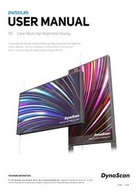
DW551LR5 - TV DynaScan - Free user manual and instructions
Find the device manual for free DW551LR5 DynaScan in PDF.
| Product Type | Professional TV (LCD monitor) |
| Brand | DynaScan |
| Model | DW551LR5 |
| Screen size | 55 inches (estimated) |
| Weight | Not specified in the manual |
| Power supply | 100-240 V, 50/60 Hz (power adapter included) |
| Power consumption | Not specified |
| Wireless connectivity | WiFi 2.4 GHz (2412-2462 MHz band, max output power 50 mW) |
| Main functions | LCD display, HDMI/DP inputs, infrared remote control |
| Included accessories | Power cable, remote control, AAA batteries (x2), quick start guide, ESK302 mounting kit |
| Maintenance and cleaning | Use a soft, lint-free cloth; do not use chemicals; disconnect before cleaning |
| Safety | Mandatory grounding; minimum RF separation distance 20 cm; do not open the cover |
| Repairability | Contact a certified DynaScan professional; do not disassemble yourself |
| Warranty | Not covered for image retention |
| Standards | Compliant with FCC Part 15 Class A; EU Directive 2014/53/EU |
| Manufacturer | DynaScan Technology Corp. |
Frequently Asked Questions - DW551LR5 DynaScan
User questions about DW551LR5 DynaScan
0 question about this device. Answer the ones you know or ask your own.
Ask a new question about this device
Download the instructions for your TV in PDF format for free! Find your manual DW551LR5 - DynaScan and take your electronic device back in hand. On this page are published all the documents necessary for the use of your device. DW551LR5 by DynaScan.
USER MANUAL DW551LR5 DynaScan
55” Clean Back High Brightness Display
Please read this manual carefully before operating the product and keep it for future reference. The use of diagrams and illustrations in the manual are for reference only, the actual product may be different.

Contents
Material Contents Declaration 2
Recycling and Energy Information 2
Declaration of Conformity 3
Safety Precautions 5
Important Safety Information 7
Getting Started 9
Contents 9
Installing and Replacing Remote Control Batteries 9
Installation 11
Connecting to a Power Source 13
Connecting an External Video Source 13
Input/OutputTerminals 14
Operating Instructions 15
Powering On/Off the Display 15
Using the Remote Control 16
Using the built-in keypad 18
Navigating the On Screen Display (OSD) Menu 19
Specifications 25
Input Mode 26
Pin Assignments 27
RS-232 Input 27
Troubleshooting 28
About DSM365 29
About SDM 30
Install SDM on the display 30
Switch to SDM 31
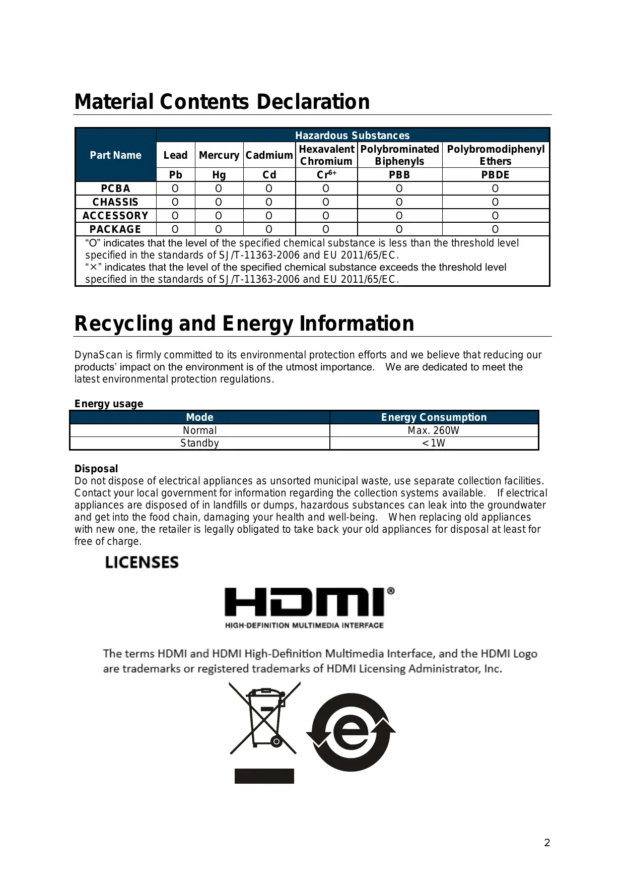
Material Contents Declaration
| Part Name | Hazardous Substances | |||||
| Lead | Mercury | Cadmium | Hexavalent Chromium | Polybrominated Biphenyls | Polybromodiphenyl Ethers | |
| Pb | Hg | Cd | Cr6+ | PBB | PBDE | |
| PCBA | O | O | O | O | O | O |
| CHASSIS | O | O | O | O | O | O |
| ACCESSORY | O | O | O | O | O | O |
| PACKAGE | O | O | O | O | O | O |
| “O” indicates that the level of the specified chemical substance is less than the threshold level specified in the standards of SJ/T-11363-2006 and EU 2011/65/EC. “×” indicates that the level of the specified chemical substance exceeds the threshold level specified in the standards of SJ/T-11363-2006 and EU 2011/65/EC. | ||||||
Recycling and Energy Information
DynaScan is firmly committed to its environmental protection efforts and we believe that reducing our products' impact on the environment is of the utmost importance. We are dedicated to meet the latest environmental protection regulations.
Energy usage
| Mode | Energy Consumption |
| Normal | Max. 260W |
| Standby | < 1W |
Disposal
Do not dispose of electrical appliances as unsorted municipal waste, use separate collection facilities. Contact your local government for information regarding the collection systems available. If electrical appliances are disposed of in landfills or dumps, hazardous substances can leak into the groundwater and get into the food chain, damaging your health and well-being. When replacing old appliances with new one, the retailer is legally obligated to take back your old appliances for disposal at least for free of charge.
LICENSES

HIGH-DEFINITION MULTIMEDIA INTERFACE
The terms HDMI and HDMI High-Definition Multimedia Interface, and the HDMI Logo are trademarks or registered trademarks of HDMI Licensing Administrator, Inc.

Declaration of Conformity
FCC
This device complies with Part 15 of the FCC Rules. Operation is subject to the following two conditions: (1) this device may not cause harmful interference, and (2) this device must accept any interference received, including interference that may cause undesired operation.
FEDERAL COMMUNICATIONS COMMISSION INTERFERENCE STATEMENT
This equipment has been tested and found to comply with the limits for a Class A digital device, pursuant to part 15 of the FCC Rules. These limits are designed to provide reasonable protection against harmful interference when the equipment is operated in a commercial environment. This equipment generates, uses, and can radiate radio frequency energy and, if not installed and used in accordance with the instruction manual, may cause harmful interference to radio communications. Operation of this equipment in a residential area is likely to cause harmful interference in which case the user will be required to correct the interference at his own expense.
CAUTION:
Any changes or modifications not expressly approved by the grantee of this device could void the user's authority to operate the equipment.
RF exposure warning
This equipment must be installed and operated in accordance with provided instructions and the antenna(s) used for this transmitter must be installed to provide a separation distance of at least 20 cm from all persons and must not be co-located or operating in conjunction with any other antenna or transmitter. End-users and installers must be provided with antenna installation instructions and transmitter operating conditions for satisfying RF exposure compliance.
Manufacturer Name
DynaScan Technology Corp.
Manufacturer Address
6F, No. 88 Wenmao Rd., Guishan Dist, Taoyuan City 333001,Taiwan
CE
This device complies with Directive 2014/53/EU issued by the Commission of the European Community.
- Frequency bands and Powers
a. WIFI 2.4G-2412~2462MHz.
b. Maximum radio-frequency power transmitted in the 2.4GHz is 50mW .
6F, No. 88 Wenmao Rd., Guishan Dist, Taoyuan City 333001,Taiwan

| CAUTION | |
| Do not install near flammable material or any heat sources. | |
| Do not defeat the safety purpose of the grounding-type plug. | |
| Do not disassemble the display to avoid electrical shock or burn. | |
| Normal operating condition considers installation at an altitude below 2000m; some abnormalities may be experienced when installed at an altitude above 2000m. |
| WARNING | |
| ! | Please power off the LCD and the video source before plugging in the DP or HDMI cable. |
| Please installed the display in well-ventilated place, do not install in a confined space. | |
| Suitable for mounting on concrete or other non-combustible surface only. | |
| If it gives off smoke, strange smell, or unusual noise, or when it gets too hot to touch, immediately unplug the display and contact the dealer. | |
| Clean only with soft, dry cloth but not use chemical liquids, and unplug while cleaning. | |
| Do not use extreme force or any sharp or pointed objects to touch the display. | |
| Do not drop or allow any object to fall to the display. | |
| Do not operate the display with wet hands to avoid electric shock. | |
| Do not discard this product with general household waste. Please be sure to comply with the local waste regulations. | |
| This device uses, generates and radiated radio frequency energy. The radio frequency energy produced by this device is well below the maximum exposure allows by Federal Communications Commission (FCC). | |
| When a stationary or fixed image is displayed on the screen for a long time, the image may be permanently imprinted on the screen. This phenomenon is known as image burn-in and is not covered by the manufacturer's warranty. | |
| In order to avoid burn-in, avoid prolonged display of static or fixed images on the screen. | |
| Power supply cord must not be attached to the building surface, nor run through walls, ceilings, floors and similar openings in the building structure. | |
| Power cord shall be connected to a socket-outlet with earthing connection. | |
| PRÉCAUTIONS | |
| N'installez pas installer à proximé de matériaux inflammables ou de sources de chaleur. | |
| Ne pas compromètre la sécurité de la fiche de mise à la terre. | |
| Pour éviter tout choc électrique ou la brûlure, ne démontez pas l'écran. | |
| Le produit peut normalément être utilisé à une altitude inférieure à 2000 m. Des anomalies peuvent survenir lors de l'installation de l'appareil à une altitude supérieure à 2000 m. | |
Disassembling the LCD is strictly prohibited. Opening the cover may expose the user to electric shock or other hazards. Please contact DynaScan certified service professionals for all maintenance requirements.
- Do not allow any liquid to enter the LCD. Also avoid placing the LCD close to water sources.
- Do not place heavy objects on the power cord. A damaged power cord might cause electric shock or fire.
- Do not bend, twist, or damage the power cord.
- The power cord must comply with the local safety regulations.
- Do not damage or modify the prongs/pins and the ground contact on the power cord plug.
- Do not place the LCD on an unleveled surface or an unstable vehicle. The LCD could fall over and cause substantial damage.
- Do not cover the vents and/or the heat sink.
- Do not install the LCD beside radiators or other heat sources. The installation site should have sufficient ventilation so the heat generated by the LCD can be dissipated.
- Do not use the Signage in a hot, humid, dusty, or fumy environment.
- Handle the LCD with care. Save the packaging materials for transport later.
Clean the LCD backside at least once a month for dust and other particles.
Unplug the LCD immediately and contact a DynaScan certified service professional as soon as possible when any of the following situations occurs:
Damaged power cord or power plug.
If liquid or foreign object has entered the LCD.
If the LCD has been exposed to rain or water.
If the LCD has been dropped or the casing has become damaged.
If any structural damage such as cracks or unnatural vibration is found.
If the LCD cannot be operated following the steps outlined in this manual.
If the LCD emits smoke or other odors, or generates strange noises.
Operating Suggestions
- Avoid displaying a stationary image for a long period of time in order to prevent image sticking.
Cleaning the Panel
- Use a soft, lint-free cloth to gently wipe the dust off from the screen panel.
- Do not use any hard material to wipe the panel.
- Do not poke the panel with your hand or any sharp object (such as a pen or a nail) or exert excessive pressure on the panel to prevent any damage.
- Do not use any cleaning solutions on the panel as it might cause discoloration.
Cleaning the Casing
Unplug the power cord.
Gently wipe the casing with a soft cloth.
Attention
- Do not use any of the following solutions to clean the casing as they may damage the paint and cause it to crack or peel: benzene solution, alkaline solution, alcohol-based cleaning solution, glass cleaner, wax, polisher, or detergent.
Confirm that the accessories below are shipped along with the display. If any item is missing, please contact your dealer. The color and shape of the accessories may vary with the products.
DW551LR5 Professional LCD.
Power cable x1 pc.
Remote Control x 1 pc.
Quick Start Guide x1 pc.
-
Batteries (1.5V / AAA) x2 pcs.
-
ESK302 x1 pc. (optional kit)
Attention: Please use the following table to check whether the included power cord is suitable for your region. If the power cord does not match your region, please contact your local supplier. Please use matching AC socket in order to meet your local safety regulations.
| Plug Type | North America | European Continental | Japan | Taiwan |
| Plug Shape | ||||
| Region | U.S.A. / Canada | EU (Except U.K.) | Japan | Taiwan |
| Voltage | 120V | 230V | 100V | 110V |
| NEMA TYPE | NEMA 5-15 | CEE 7/7 | NEMA 1-15 | NEMA 5-15 |
| IEC Display Plug | ||||
| IEC Plug TYPE | IEC320 C13 | |||
Installing and Replacing Remote Control Batteries
- Open the battery compartment cover.
- Insert 2 new AAA batteries.
- Close the battery compartment cover.
Warning:
Incorrect usage of batteries may cause leakage or explosion.
- Pay attention to the polarity when installing the batteries.
- Do not mix different types of batteries or new and used batteries. Doing so may shorten the battery life or cause leakage.
- Remove or replace the batteries when they are empty in order to prevent acid leaking in the battery compartment.
- Do not touch the leaked substance from the batteries in case of a battery leakage. Doing so may hurt human skin.
Note: If the remote control is not going to be used for a long time, we recommend removing the batteries from the remote control.
Contenu
Incorrect installation may cause injury or damage the equipment. Product warranty does not cover the damage caused by improper installation and DynaScan shall not be held responsible in such incident.
Orientation
Take off the cover on the rear of display and the orientation sticker can be found inside, which is for distinguishing the direction of installation.
Installation Location
- Do not install in a location with strong vibrations or dusty.
- Do not install near the building's main electric panel.
- Ensure the LCD is secured in such a manner that it cannot be easily removed by the general public.
- Leave clearance around the outer edge of the LCD from other objects to ensure proper ventilation.
Single display
Maintenance
- Inspect the fasteners regularly for signs of loosening or deformation. Please perform appropriate corrective measures when a problem is identified. Neglecting the problem may worsen the situation.
- Increase the inspection frequency on areas where previous maintenance had occurred to ensure the problems do not occur again.
Connecting to a Power Source
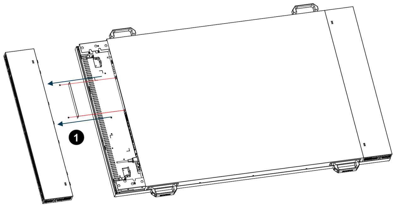
Take off the cover from the back of display. Using the power cable provided, plug it in the power inlet which shown in the diagram below. Connect the power cable to a 100-240 volt, 50 / 60Hz AC power outlet.

Insert the plug completely into the socket. A loose power connection may cause damage to the way and/or lead to a fire hazard.
Connecting an External Video Source
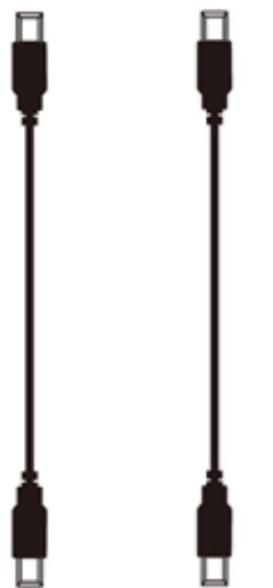
Turn OFF the power of both LCD and external video device. Take off the cover from the back of display. Using the DP cable (or HDMI cable) provided, insert one end into the DP-IN (or HDMI 1-IN, HDMI 2-IN) which shown in the diagram below. Connect the other end of the DP cable (HDMI cable) to the DP output (or HDMI output) of the video source. Refer to your video device's manual for additional information.
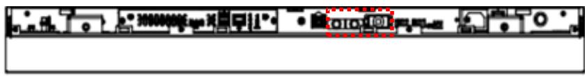
HDMI 1-IN HDMI 2-IN
HDMI-OUT HDMI-OUT
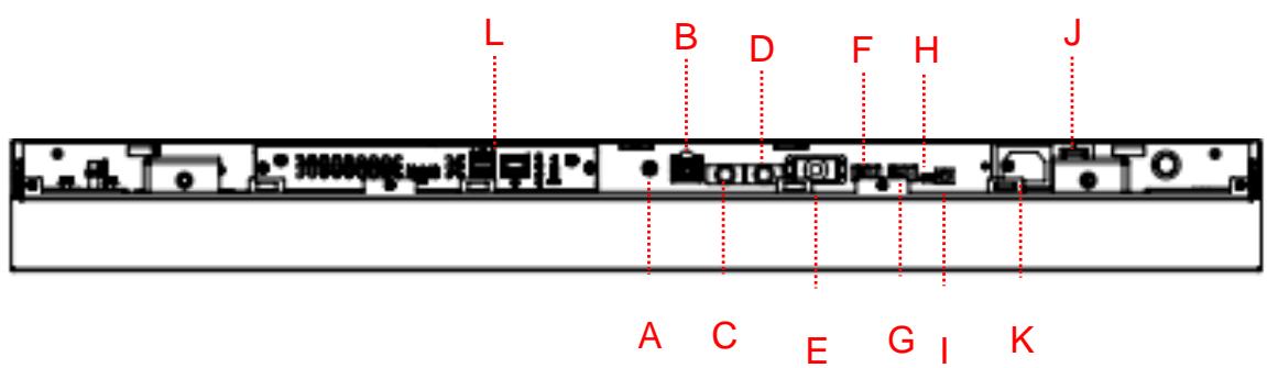
Input / Output Terminals
A. Audio (OUT): Connect the audio signal output from Audio IN jack to an external AV device.
B. RJ-45 (IN): RJ45 network input connection.
C. HDMI 1 (IN): Connect the HDMI output of a PC or an AV device via a HDMI cable.
D. HDMI 2 (IN): Connect the HDMI output of a PC or an AV device via a HDMI cable.
E. RS-232 (IN): RS232C network input connection for remote control from PC.
F. USB 2.0 port: Support for USB flash drive storage, mouse and keyboard.
G. USB 2.0 port: Support for USB flash drive storage, mouse and keyboard.
H. Extension Connector: Extension Connector for optional IR Extension sensor kit (ESK302).
I. Thermal: Extension Connector for optional Extension thermal kit (ETK302).
J. Power Switch: Press to switch the main power on/off.
K. AC (IN): Connect the supplied power cord to the wall outlet.
L. SDM Slot: Install SDM, please refer to P.30
*USB 2.0 port: A standardized port to connect a variety of devices like mouse, keyboard, and flash drive. Support USB storage devices formatted with NTFS, FAT32 (32G) file system.
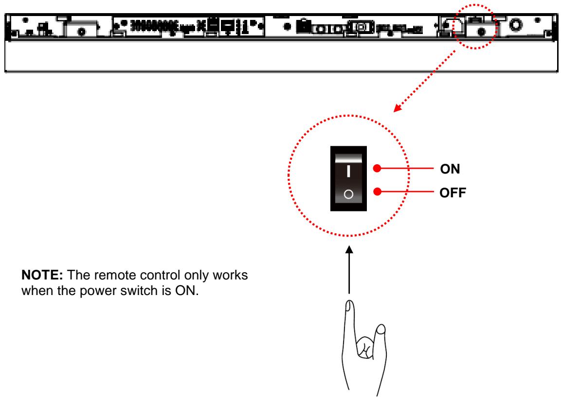
Powering On/Off the Display
To turn on/off the display, take off the cover from the back of display first. Press the power switch on as shown in the diagram below.
Using the Remote Control
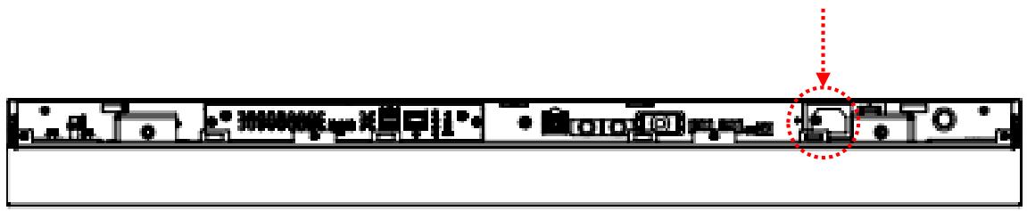
Connection using an External Sensor Kit (ESK302)
Take off the cover from the back of display. Connect the ESK302 cable (optional kit) to the mini USB port, and aim the remote at the IR receiver as shown below. Meanwhile, the IR receiver on the display will be disabled.
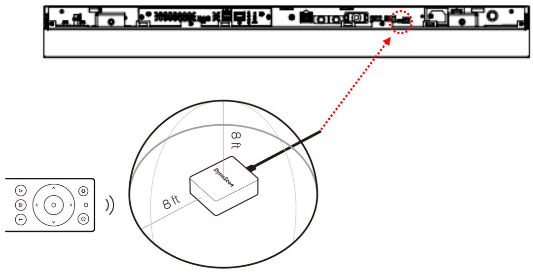
NOTE: Ambient light may affect the performance of the remote control. Avoid fluorescent or neon lights in the vicinity.
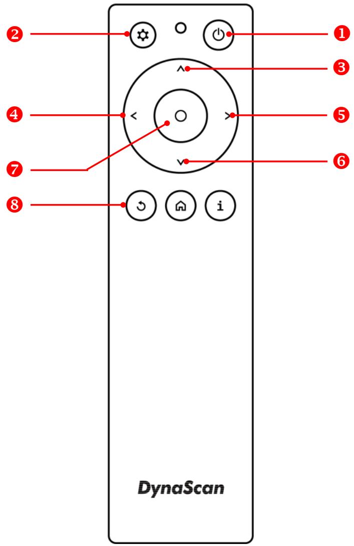
*Color and shape may vary by model.
| ITEM | DESCRIPTION | |
| 1 | POWER | Power On / Off |
| 2 | MENU | OSD On / Off |
| 3 | UP | Move the cursor up or change the setting of selected item. |
| 4 | LEFT | Exit the current selection. |
| 5 | RIGHT | Select the highlighted item. |
| 6 | DOWN | Move the cursor down or change the setting of selected item. |
| 7 | OK | Enter (for DSM365 only) |
| 8 | BACK | Return to the last page. (for DSM365 only) |
Using the built-in keypad
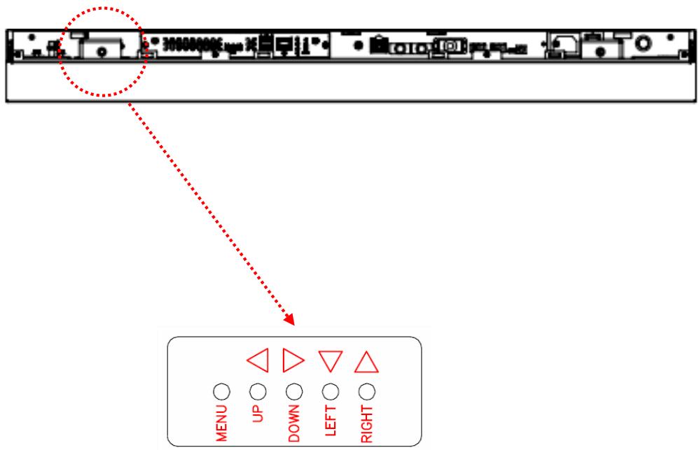
| ITEM | DESCRIPTION |
| MENU | OSD On / Off, Power On / Off. |
| UP | Move the cursor up or change the setting of selected item. |
| DOWN | Move the cursor down or change the setting of selected item. |
| LEFT | Exit the current selection. |
| RIGHT | Select the highlighted item. |
Navigating the On Screen Display (OSD) Menu
Press the MENU button on the built-in keypad or remote control to show the OSD. Use the navigation arrows to select and adjust the menu items.
*The change of each setting can only enable when you press "LEFT" (refer to p.14) to back to the last menu layer.
1. Input Source
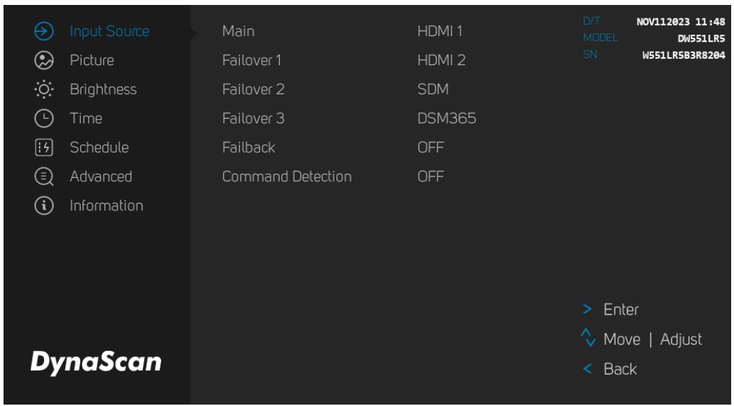
| ITEM 1 | ITEM 2 | DEFAULT | DESCRIPTION |
| Input Source | Main | HDMI 1 | Set the Main input to display. |
| Failover 1 | HDMI 2 | Set the Failover 1 input to display. | |
| Failover 2 | SDM | Set the Failover 3 input to display. | |
| Failover 3 | DSM365 | Set the Failover 4 input to display. | |
| Failback | OFF | Set the time (hour),when the Input Source is failover, it will redetection the Main Source per few hour. | |
| Command Detection | OFF | Only effective in Main input source. If the display didn't get both of commend and the input signal, it will change to Failover1 input. |
2. Picture
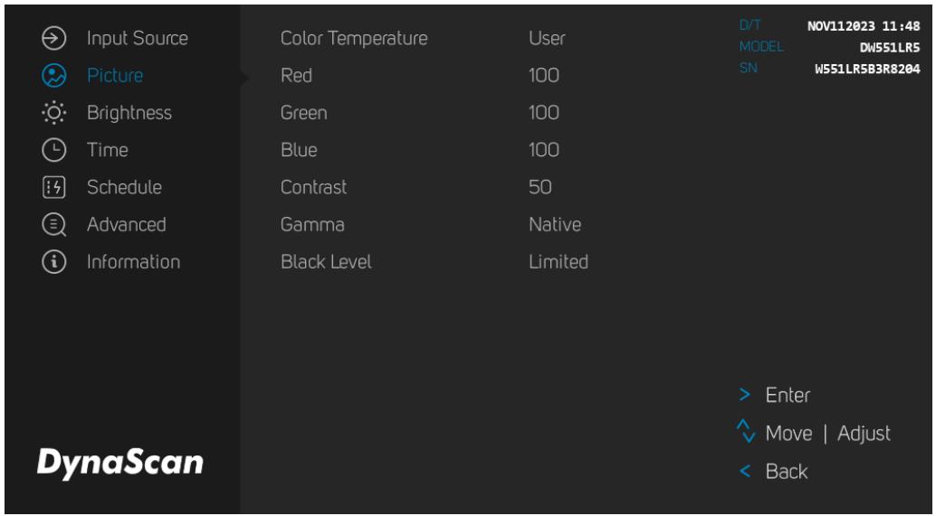
| ITEM 1 | ITEM 2 | DEFAULT | DESCRIPTION |
| Picture | Color Temperature | USER | Adjusts the color temperature to preset or user determined values. (User, D55, D65, D93, Balanced) |
| Red | 100 | Adjust the red light level. Range 0 – 100. Note: The feature is only supported on User mode. | |
| Green | 100 | Adjust the red light level. Range 0 – 100. Note: The feature is only supported on User mode. | |
| Blue | 100 | Adjust the red light level. Range 0 – 100. Note: The feature is only supported on User mode. | |
| Contrast | 60 | Adjust the contrast level. Range 0 – 100. | |
| Gamma | Native | Adjusts the Gamma value. (Native, 2.2, 2.4 and sGamma) | |
| Black Level | Limited | Selects the black level to adjust the screen gray scale. "Limited" for video source uses 16 to 235 levels for R/G/B, such as HDMI. "RGB Full" for video source uses all levels from 0 to 255 levels. "Auto" is for detecting the video source to determine its value is applicable for "Limited" or "RGB Full". |
3. Brightness
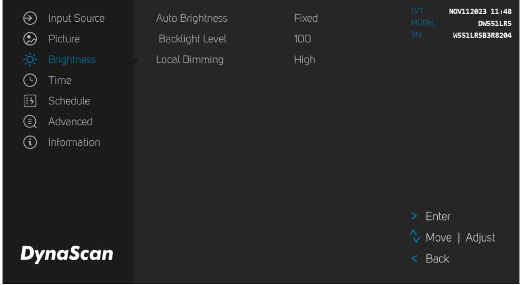
| ITEM 1 | ITEM 2 | DEFAULT | DESCRIPTION |
| Brightness | Auto Brightness | Fixed | Brightness Setting :Fixed:screen brightness remains at one level.Timer:Screen brightness is determined by the time of day. Auto:Screen brightness is determined by an extension sensor kit (ESK). Mix:Mix Timer & Auto Mode,Autosensor time screen brightness determined by an extension sensor kit (ESK); fixed time by timer. By Light Value:Screen brightness determined by ambient light values, up to 4 levels. By Time:Screen brightness determined by scheduled values, up to 4 levels. |
| Backlight Level | 100 | ||
| Local Dimming | UDR | Optimizes contrast by adjusting brightness in individual sections of the screen.(UDR, Local Dimming1/2) |
4. Time
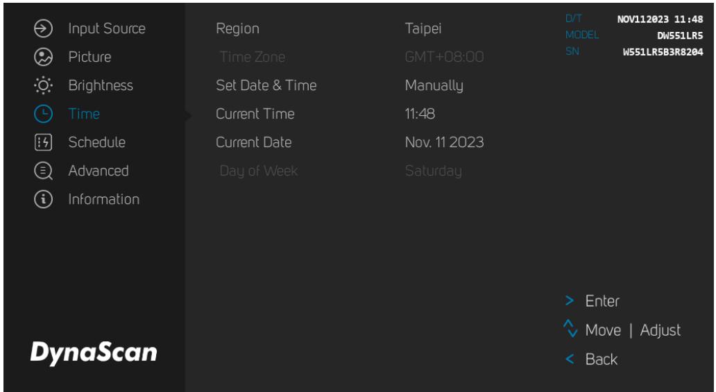
| ITEM 1 | ITEM 2 | DEFAULT | DESCRIPTION |
| Time | Region | ||
| Time Zone | Set the Time Zone. | ||
| Set Date & Time | Set the mode. | ||
| Current Time | Set the clock.Note: The internal clock will continue to function when the power is turned off. | ||
| Current Date | Set the date. | ||
| Day Of Week | Set the day of week. (Monday to Sunday) |
5. Schedule
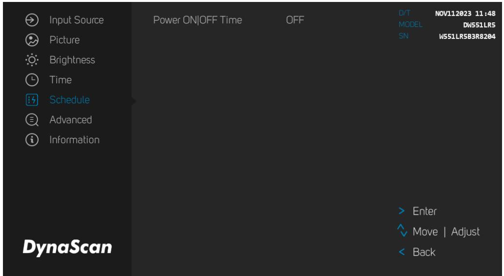
| ITEM 1 | ITEM 2 | DEFAULT | DESCRIPTION |
| Schedule | Power ON/OFF Time | OFF | Automatic power on / off schedule function. |
6. Advanced
| Input Source | Display Mode | Auto | D/T | NOV112023 11:48 |
| Picture | Screen Protection | OFF | MODEL | DW551LRS |
| Brightness | IR Control | ON | SN | WS51LR5B3R8204 |
| Time | Power Restore Behavior | Power On | ||
| Schedule | Audio Out Volume | 50 | ||
| Advanced | Source Info | ON | ||
| Information | RS232 CMD Compatible | OFF | ||
| Schedule Reboot | OFF | |||
| OSD Password Protection | OFF | |||
| Export & Import Settings | ||||
| Reset Default Settings | > Enter | |||
| ^ Move | Adjust | ||||
| DynaScan | < Back | |||
| ITEM 1 | ITEM 2 | DEFAULT | DESCRIPTION |
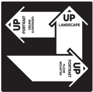
| Advanced | Display Mode | Auto | Change the Menu orientation. The Menu can be displayed in either LANDSCAPE, PORTRAIT or PORTRAIT FLIP mode.Note: When adjusting the Display Mode or changing the screen orientation, the system will automatically reboot as part of its standard procedure. |
| Screen Protection | Off | Turn on / off image burn-in protection.Set image burn-in protection interval.Range 0 - 100 minutes. | |
| IR Control | On | Enable/disable the remote control for Menu.Note: When disabled, the remote control function can be enabled again from the control panel on the display or through the DynaScan “Display Manager” application. | |
| Power Restore Behavior | Power On | Choose to use the AC back status function.Power On: Display booting up when the power back after an outage.Standby: Display keeps soft-off status when the power back after an outage.Memory: Display will back to the last state when the power back after an outage. | |
| Audio Out Volume | 50 | Set volume.Range 100 - 0. | |
| Source Info | ON | Enable/disable the Source Information. | |
| RS232 CMD Compatible | OFF | RS232 Command compatibility between the current and last generation* model. * last generation model: DS371BT4、DS491LT4、DS552LT4-1、DS552LT4-M、DS552LT5、DS552LT6-1、DS552LT7、DS551DR4、DI551ST2、DW551LR5、DO552LR4、DO551LR4、DO552LR4-M、DI651ST2、DP652ST2、DP652LT5 | |
| Schedule Reboot | OFF | Enable/disable the Schedule Reboot, And set the Time. | |
| OSD Password Protection | OFF | Turn On: Create Password > ConfirmPassword > Password Protection On Turn Off: Enter Password > Password Protection Off | |
| Export & Import Settings | Export or Import OSD Setting by USB. | ||
| Reset Default Setting | Restore all settings to default.Note: It does not modify CURRENT DATE, CURRENT TIME, DATE OF WEEK, TIME ZONE, POWER ON TIME and POWER OFF TIME. |
7. Information

Input Source

Picture

Brightness

Time

Schedule

Advanced

Information
DynaScan
Resolution
MCB Version
FW Version
OS Version
Thermal Kit Temp.
DSM365 1920 x 1080
07400
10400
11.3904
NA
D/T
MUEL
3N
NOV112023 11:48
DN55S1LR5
W551LR5B3R8204
Enter

Move | Adjust

Back
| ITEM 1 | ITEM 2 | DEFAULT | DESCRIPTION |
| Information | Resolution | Input resolution. | |
| MCB Version | The MCB version. | ||
| FW Version | The F/W version. | ||
| OS Version | LCD inner (backlight unit) temperature monitoring. | ||
| Thermal Kit Temp. | The Extension Thermal Kit (ETK302) is for ambient temperature monitoring. |
Some functions may not be available for all models.
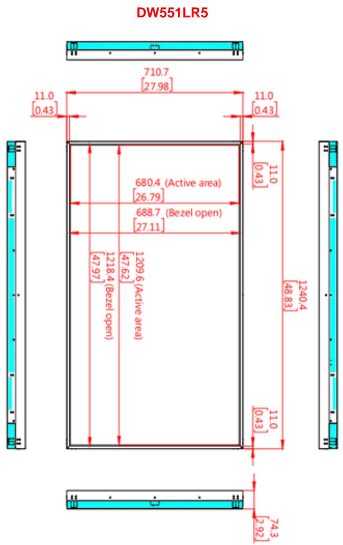
| MODEL | DW551LR5 | |
| PANEL | LCD Panel Size | 54.64 inches |
| Native Resolution | 1920 x 1080 | |
| Brightness | 4000 cd/m² (Typ.) | |
| Contrast Ratio | 3,000:1 | |
| Response Time | 9 ms (Typ.) | |
| Viewing Angle | 178°/ 178° | |
| Life Time | 100,000 hrs (Typ.) | |
| Panel Surface | AR, 2H | |
| POWER | Power Supply | Internal |
| Rated Voltage | 100 - 240V, 50 / 60Hz | |
| Power On Mode | Typ. 140W / Max. 260W | |
| Power Saving Mode | < 1W | |
| MECHANICAL SPECS | Bezel Width (T/B/L/R) | 11.0 / 11.0 / 11.0 / 11.0 mm |
| Cabinet Color | Black | |
| Monitor Dimension (LxHxD) | 1240.4 x 710.7 x 74.3 mm | |
| Monitor Weight (set / package) | 27 kg / TBD | |
| Orientation | Landscape / Portrait / Portrait Flip | |
| USER INTERFACE | OSD Language | English |
| ENVIRONMENT | Operation Temperature | 0°C ~ 45°C |
| Storage Temperature | -20°C ~ 60°C | |
| Humidity | 10%~80% RH Non-Condensing | |
| I/O Ports | HDMI | IN *2 (HDCP) |
| DP | N/A | |
| RS-232 | IN *1 | |
| Audio | OUT *1 | |
| USB port | IN *2 | |
| RJ-45 | IN *1 | |
| Micro SD card | N/A | |
| Fuse | 6.3A | |

Design and specifications are subject to change without notice.
| Active Resolution | Refresh Rate | |
| H Pixels | V Lines | |
| 640 | 480 | 60 Hz |
| 720 | 480 | 60 Hz |
| 800 | 600 | 60 Hz |
| 960 | 600 | 60 Hz |
| 1024 | 768 | 60 Hz |
| 1280 | 720 | 60 Hz |
| 1280 | 768 | 60 Hz |
| 1280 | 960 | 60 Hz |
| 1280 | 1024 | 60 Hz |
| 1366 | 768 | 60 Hz |
| 1400 | 1050 | 60 Hz |
| 1440 | 900 | 60 Hz |
| 1600 | 1200 | 60 Hz |
| 1680 | 1050 | 60 Hz |
| 1920 | 720 | 60 Hz |
| 1920 | 1080 | 60 Hz |
| 1920 | 1200 | 60 Hz |
| 1920 | 1440 | 60 Hz |
| 2560 | 1440 | 60 Hz |
| 3840 | 2160 | 60 Hz |
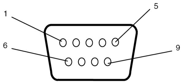
RS-232 Input
| PIN No. | NAME |
| 01 | Connected to 7&8 |
| 02 | TXD |
| 03 | RXD |
| 04 | Connected to 6 |
| 05 | GND |
| 06 | Connected to 4 |
| 07 | Connected to 1&8 |
| 08 | Connected to 1&7 |
| 09 | NC |
| ISSUE | RECOMMENDED SOLUTION |
| No image is displayed. | Check whether the cable is completely plugged in. Check whether the main switch is in the ON position, and the power cord is completely plugged in. Check whether the image source's resolution is set as the supported format (refer to section “Input Mode”, p.22). Check whether the cable is damaged or bent excessively. |
| Nothing happens when switching the main switch on. | Unplug the power cord from the socket and plug it in again after a few seconds to reset the Signage. Note: Unplugging the power cord will not change the settings. |
| Image is unstable. | Check whether the cable is completely plugged in. |
| The remote control does not work. | Check whether there are batteries in the remote control. Check the batteries for freshness, polarity, etc. Check whether the remote is in the operation range. Bright light may interfere with the remote control. Please avoid using the remote control near special fluorescent lights or neon lights. |
| Auto on/off does not work or does not function properly. | Check whether the TIMER setting in the menu is set to “OFF”. Check whether the “Power On Time” and “Power Off Time” settings are set correctly. |
| Cannot control the display remotely via RS-232. | Check whether the RS-232 cable is connected properly. |
If you are still having trouble with your DynaScan DS² Professional LCD, contact your dealer or DynaScan directly for more assistance.
DSM365 is an internal operating system as Android, which can install the applications via USB flash drive storage, SD card or Internet.
How to Switch to DSM365
- Press the MENU button on either the rear panel control or remote control to show the OSD.
- Use the navigation arrows to select and adjust the Input Source.
[Input Source Main DSM365]


| ITEM | DESCRIPTION | |
| 1 | APPS | Show the Installed APPS. |
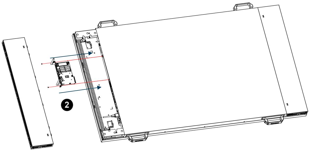
Install SDM on the display
*Note: SDM must comply with Rated Power DC 12V 45W (Max 50W) and IEC 62368-1 Standard.
- Loosen screws and remove the SDM cover from the display.
- Insert the SDM module into the display and fasten screws. Make sure the SDM properly installed to avoid causing the devise destruction.
Switch to SDM
- Press the MENU button on either the rear panel control or remote control to show the OSD.
- Use the navigation arrows to select and adjust the Input Source.
[Input Source Main SDM]

www.dynascandisplay.com