
MIT-W102 - Laptop Advantech - Free user manual and instructions
Find the device manual for free MIT-W102 Advantech in PDF.
| Product Type | Mobile computer (rugged tablet) |
| Brand | Advantech |
| Model | MIT-W102 |
| Dimensions (approx.) | 270 x 180 x 20 mm |
| Weight (approx.) | 1.2 kg |
| Display | 10.1-inch touchscreen |
| Processor | Intel Celeron or comparable |
| Memory (RAM) | 4 GB |
| Internal storage | 64 GB eMMC |
| Operating system | Windows 10 IoT Enterprise |
| Power supply | Power adapter 19 V DC, 3.15 A (model Delta MDS-060AAS19 B) |
| Battery | Li-Ion rechargeable (replacement by qualified technician) |
| Wireless connectivity | WiFi 5 GHz / 2.4 GHz, Bluetooth |
| Ports | USB, HDMI, headphone jack, card reader |
| Protection | IP65 rating (dust and water jet resistant) |
| Operating temperature | 0 °C to 50 °C |
| Storage temperature | -20 °C to 60 °C |
| Maintenance and cleaning | Use a dry cloth; do not use liquid or aerosol detergents. |
| Battery - warning | Replace only with an identical model; explosion risk if incorrectly replaced. |
| Standards | CE, FCC, IC, compliant with Industry Canada RSS |
Frequently Asked Questions - MIT-W102 Advantech
User questions about MIT-W102 Advantech
0 question about this device. Answer the ones you know or ask your own.
Ask a new question about this device
Download the instructions for your Laptop in PDF format for free! Find your manual MIT-W102 - Advantech and take your electronic device back in hand. On this page are published all the documents necessary for the use of your device. MIT-W102 by Advantech.
USER MANUAL MIT-W102 Advantech
MIT-W102XXXXXXXXXXXXXX
User Manual
MIT-W102
Ver 1.1
Copyright
The documentation and the software included with this product are copyrighted 2020 by Advantech Co., Ltd. All rights are reserved. Advantech Co., Ltd. reserves the right to make improvements in the products described in this manual at any time without notice. No part of this manual may be reproduced, copied, translated or transmitted in any form or by any means without the prior written permission of Advantech Co., Ltd. Information provided in this manual is intended to be accurate and reliable. However, Advantech Co., Ltd. assumes no responsibility for its use, nor for any infringements of the rights of third parties, which may result from its use.
Acknowledgements
All other product names or trademarks are properties of their respective owners.
Intended use
The MIT-W102 is intended for integration with hospital system. It is designed for general purpose for hospital environment. For data collection and display for reference. It shall not be used for life-supporting system.
Intended user group
The primary users for the MIT-W102 series are professional healthcare personnel and general patient groups. It is appropriate for users aged between 18 and 55 to use the tablet and users' weight and health are not relevant.
Declaration of Conformity
CE Conformity Statement
Radio products with the CE alert marking comply with the RED Directive (2014/53/EU) issued by the Commission of the European Community. Compliance with this directive implies conformity to the following European Norms (in brackets are the equivalent international standards).
EN 60950-1 (IEC60950-1) - Product Safety
- EN 300 328 Technical requirement for radio equipment
EN 301 893 Technical requirement for radio equipment
ET S301 489 General EMC requirements for radio equipment
Products that contain the radio transmitter are labeled with CE alert marking and may also carry the CE logo.
FCC Compliance Statement
This device complies with Part 15 of the FCC Rules. Operation is subject to the following two conditions: (1) this device may not cause harmful interference, and (2) this device must accept any interference received, including interference that may cause undesired operation.
This equipment has been tested and found to comply with the limits for a Class B digital device, pursuant to part 15 of the FCC Rules. These limits are designed to provide reasonable protection against harmful interference in a residential installation. This equipment generates, uses and can radiate radio frequency energy and, if not installed and used in accordance with the instructions, may cause harmful interference to radio communications. However, there is no guarantee that interference will not occur in a particular installation. If this equipment does cause harmful interference to radio or television reception, which can be determined by turning the equipment off and on, the user is encouraged to try to correct the interference by one or more of the following measures:
—Reorient or relocate the receiving antenna.
—Increase the separation between the equipment and receiver.
—Connect the equipment into an outlet on a circuit different from that to which the receiver is connected.
—Consult the dealer or an experienced radio/TV technician for help.
Any changes or modifications not expressly approved by the party responsible for
compliance could void the authority to operate equipment.
FCC frequency stability Statement:
Frequency Stability: The grantee ensured that the EUT meets Section 15.407(g) requirements.
RF Exposure Information (SAR)
This device meets the government's requirements for exposure to radio waves. This device is designed and manufactured not to exceed the emission limits for exposure to radio frequency (RF) energy set by the Federal Communications Commission of the U.S. Government. The exposure standard for wireless devices employing a unit of measurement is known as the Specific Absorption Rate, or SAR. The SAR limit set by the FCC is 1.6W / kg .
The FCC has granted an Equipment Authorization for this device with all reported SAR levels evaluated as in compliance with the FCC RF exposure guidelines. SAR information on this device is on file with the FCC and can be found under the Display Grant section of www.fcc.gov/oet/ea/fccid after searching on FCC ID: TX2-RTL8822CE
IC Compliance Statement
This device complies with Industry Canada's licence-exempt RSSs. Operation is subject to the following two conditions: (1) This device may
not cause interference; and (2) This device must accept any interference, including interference that may cause undesired operation of the device.
(i) the device for operation in the band 5150-5250 MHz is only for indoor use to reduce the potential for harmful interference to co-channel mobile satellite systems;
(ii) for devices with detachable antenna(s), the maximum antenna gain permitted for devices in the bands 5250-5350 MHz and 5470-5725 MHz shall be such that the equipment still complies with the e.i.r.p. limit;
(iii) for devices with detachable antenna(s), the maximum antenna gain permitted for devices in the band 5725-5850 MHz shall be such that the equipment still complies with the e.i.r.p. limits specified for point-to-point and non-point-to-point operation as appropriate; and
(iv) the worst-case tilt angle(s) necessary to remain compliant with the e.i.r.p. elevation mask requirement set forth in Section 6.2.2(3) shall be clearly indicated.
Technical Support and Assistance
- Visit the Advantech website at http://support.advantech.com where you can find Caution! Exposure to Radio Frequency Radiation.
The radiated output of this device is far below the FCC radio frequency exposure limits. Nevertheless, the device shall be used in such a manner that the potential for human contact during normal operation is minimized.
When connecting an external antenna to the device, the antenna shall be placed in such a manner to minimize the potential for human contact during normal operation. In order to avoid the possibility of exceeding the FCC radio frequency exposure limits, human proximity to the antenna shall not be less than 20cm (8inches) during normal operation.
MIT-W102 User Manual I the latest information about the product.
-
Contact your distributor, sales representative, or Advantech's customer service center for technical support if you need additional assistance. Please have the following information ready before you call:
-
Product name and serial number
- Description of your peripheral attachments
- Description of your software (operating system, version, application software, etc.)
- A complete description of the problem
- The exact wording of any error messages
Details of preparatory treatment or disposal
Installation is only to be carried out by manufacturer authorized and trained personnel. Regarding calibrating the device, we suggest to send back the tablet to the supplier for annually check.
Safety Instructions
-
Read these safety instructions carefully.
-
Keep this user manual for later reference.
-
Disconnect this equipment from AC outlet before cleaning. Do not use liquid or spray detergents for cleaning.
-
For plug-in equipment, the power outlet socket must be located near the equipment and must be easily accessible.
-
Keep this equipment away from humidity.
-
Put this equipment on a reliable surface during installation. Dropping it or letting it fall could cause damage.
-
The openings on the enclosure are for air convection. Protect the equipment from overheating. DO NOT COVER THE OPENINGS.
-
Do not leave this equipment in an environment unconditioned where the storage temperature under -20^ or above 60^ , it may damage the equipment.
-
Make sure the voltage of the power source is correct before connecting the equipment to the power outlet.
-
Place the power cord such a way that people cannot step on it. Do not place anything over the power cord. The voltage and current rating of the cord should be greater than the voltage and current rating marked on the product.
-
All cautions and warnings on the equipment should be noted.
-
If the equipment is not used for long time, disconnect it from the power source to avoid being damaged by transient over-voltage.
-
Never pour any liquid into ventilation openings. This could cause fire or electrical shock.
-
Never open the equipment. For safety reasons, the equipment should be opened only by qualified service personnel.
-
If any of the following situations arises, get the equipment checked by service personnel:
a. The power cord or plug is damaged.
b. Liquid has penetrated into the equipment.
c. The equipment has been exposed to moisture.
d. The equipment does not work well or you cannot get it to work according to user manual.
e. The equipment has been dropped and damaged.
f. The equipment has obvious signs of breakage.

-
CAUTION: The computer is provided with a battery-powered real-time clock circuit. There is a danger of explosion if battery is incorrectly replaced. Replace only with same or equivalent type recommended by the manufacture. Discard used batteries according to the manufacturer's instructions.
-
If your computer is losing time significantly or the BIOS configuration resets itself to the default, the battery may have no power.
Caution! 1. Do not replace battery yourself. Please contact a qualified technician or your retail provider.
- The computer is provided with a battery-powered real-time clock circuit. There is a danger of explosion if battery is incorrectly replaced. Replace only
with same or equivalent type recommended by the manufacturer. Discard used batteries according to the manufacturer's instructions.
- CLASSIFICATION:
Supply Class I adapter
No applied part
Continuous Operation
Not AP or APG category
- Disconnect device: disconnect the power cord and battery to fully power off the device
- Do not place the power cord where it is difficult to disconnect and may be stepped by other persons.
- Follow national, state or local requirements to dispose of unit.
- Maintenance: to properly maintain and clean the surfaces, use only the approved products or clean with a dry applicator.
- Contact information:
No.1, Alley 20, Lane 26, Rueiguang Road Neihu District, Taipei, Taiwan 114, R.O.C.
TEL: +886 2-2792-7818
24.

E349709
4LY4
MEDICAL-GENERAL MEDICAL EQUIPMENT
WITH RESPECT TO ELECTRICAL SHOCK, FIRE AND MECHANICAL
HAZARDS ONLY IN ACCORDANCE WITH ANSI/AAMI ES60601-1
(2005 and Amendment 1) CAN/CSA-C22.2 NO.60601-1 (2014)
- This equipment shall not be used as a life support system.
- Accessory equipment connected to the analog and digital interfaces must be in compliance with the respective nationally harmonized IEC standards (i.e. IEC 60950 for data processing equipment, IEC 60065 for video equipment, IEC 61010-1 for laboratory equipment, and IEC 60601-1 for medical equipment.) Furthermore all configurations shall comply with the system standard IEC 60601-1-1. Anyone who connects additional equipment to the signal input part or signal output part is configuring a medical system, and is therefore, responsible that the system complies with the requirements of the system standard IEC 60601-1-1. The unit is for exclusive interconnection with IEC 60601-1 certified equipment in the patient environment and IEC 60XXX certified equipment outside of the patient environment. If in doubt, consult the technical services department or your local representative.
- Users must not allow SIP/SOPs to come into contact with the patient at the same time.
- The sound pressure level at the operator's position according to IEC 704-1:1982 is no more than 70dB (A).


-
WARNING - Do not modify this equipment without authorization of the manufacturer.
-
WARNING - To avoid risk of electric shock, this equipment must only be connected to a supply mains with protective earth.

- WARNING: Please avoid having enclosure to contact with skin more than 1 minute.

- CAUTION! This product: MIT-W102 is used with the
Qualified and certificated power adapter:
Delta ELECTRONICS CO LTD, model MDS-060AAS19 B. Output: 19Vdc,
3.15A max
DISCLAIMER: This set of instructions is given according to IEC 704-1. Advantech disclaims all responsibility for the accuracy of any statements contained herein.
In case of serious incident that has occurred, please contact the manufacturer and local authorities immediately.
No.1, Alley 20, Lane 26, Rueiguang Road Neihu District, Taipei, Taiwan 114, R.O.C.
TEL: +886 2-2792-7818
24.

E349709
4LY4
MEDICAL-GENERAL MEDICAL EQUIPMENT
WITH RESPECT TO ELECTRICAL SHOCK, FIRE AND MECHANICAL
HAZARDS ONLY IN ACCORDANCE WITH ANSI/AAMI ES60601-1
(2005 and Amendment 1)CAN/CSA-C22.2 NO.60601-1(2014)
RISK OF EXPLOSION IF BATTERY IS REPLACED BY AN INCORRECT TYPE.
DISPOSE OF USED BATTERIES ACCORDING TO THE INSTRUCTIONS.
Do not place the battery incorrectly as this may cause danger of explosion.
Dispose of used batteries according to the manufacturer's instructions.
Do not dispose of batteries in a fire. They may explode. Check with local authorities for disposal instructions.
Battery Pack Caution
The battery used in this device may present a risk of fire or chemical burn if mistreated. Do not disassemble, heat above 40^ , or incinerate. Replace standard battery pack with Advantech MIT-W102-BATC Li-ion 11.1V 2860mAh. Use of another battery may present a risk of fire or explosion.
Dispose of used batteries according to local disposal regulations. Keep away from children. Do not disassemble and do not dispose of in a fire.

Battery Charge Notice
It is important to consider the environment temperature whenever you are charging the Lithium- Ion battery pack. The process is more efficient at normal room temperature or slightly cooler. It is essential that you charge batteries within the stated range of 0^ C to 35^ C . Charging batteries outside of
the specified range could damage the batteries and shorten their charging life cycle.
Storage and Safety Notice
Although charge Lithium-lon batteries may be left unused for several months, their capacity may be depleted due to the buildup of internal resistance. If this happens they will require recharging prior to use. Lithium-lon batteries may be stored at temperatures between -20^ to 60^ , however they may be depleted more rapidly at the high end of this range. It is recommended to store batteries within normal room temperature ranges.
Disposing of Batteries or Battery Pack.
Batteries, battery packs, and accumulators should not be disposed of as assorted household waste. Please use the public collection system to return, recycle, or treat them in compliance with the local regulations.
Chapter 1 Ready to Go. 16
1.1 Symbols Used in this Manual 17
1.2 Product Features 17
1.3 Package Contents 18
1.4 System Configuration 19
1.6 Exploring the MIT-W102 20
1.6.1 Front View 20
1.6.2 Rear View 21
1.6.3 Right View 22
1.6.4 Left View 22
1.6.5 Top View 23
1.6.6 Bottom View 23
Chapter 2 Making Connections 24
2.1 Connecting the Power 25
2.2 Connecting to a Monitor 25
2.3 Connecting USB Devices 26
2.4 Connecting Headphones 26
2.5 Connecting a Microphone 27
Chapter 3 Turning On 28
3.1 Controlling the MIT-W102 29
3.1.1 Using the Touch Screen 29
3.1.2 Using the Tap Function 29
3.1.3 Using the Control Panel Buttons 29
3.1.4 Using the On-Screen Keyboard 30
3.1.5 Adjusting Screen Brightness 33
3.1.6 Adjusting the Volume 34
Chapter 4 Wireless Connections 35
4.1 Wi-Fi Connection 36
4.2 Bluetooth Connections 39
4.2.1 Setting Up Bluetooth 39
Chapter 5 Advance Setting 43
5.1 Checking Battery Status 44
5.2 Maintenance 44
5.2.1 Maintaining the Battery 44
5.2.2 Maintaining the LCD Display 45
5.2.3 Cleaning the MIT-W102 45
5.3 Trouble Shooting 45
Chapter 6 Dashboard and Hotkey setting 49
6.1 Dashboard 50
6.2 NFC 50
6.2.1 NFC application 50
6.2.2 NFC Setting 51
6.2.3 NFC Usage 53
6.3 Camera 53
6.4 Brightness 56
6.5 Hotkey Setting 57
Appendix Specifications 58
A.1 Specifications 59
A.2 Optional Accessories 61
A.2.1 External Battery 61
A.2.2 Office Docking Station 62
A.2.3 VESA Docking Station 66
A.2.4 Adjustable Stand (with the hand strap) 68
A.2.5 Rubber Bumper 71
A.3 Installing SSD 73
Chapter 1 Ready to Go
Congratulations on your purchase of the MIT-W102 Rugged Tablet PC. This product combines rugged design with reliable performance and powerful functionality to best suit all your needs, in a wide range of working conditions. This user manual outlines all you need to know to set up and use your MIT-W102. If you have any further questions or queries, contact our technical support team via our website:
1.1 Symbols Used in this Manual

Denotes information that must be observed.
Failure to do so may result in personal harm or damage to the product.
Denotes information that must be observed.
Failure to do so may result in personal harm or damage to the product.
1.2 Product Features
Rugged design.
- Featuring with the Future Intel® Pentium™ processor for intelligent system.
Built-in WLAN/Bluetooth/NFC
- Durable, shock-resistant magnesium alloy housing.
10.1 “WUXGA TFT LCD
- Power Requirements
DC Input Voltage: 19 V
Power Consumption: less than 60 W
1.3 Package Contents
Ensure all the following items are present when you receive your MIT-W102. If any of these items are missing, contact your vendor immediately.

Screens used in this manual are for illustrative purposes only. Actual screens may vary depending on your product version.
- MIT-W102 Tablet PC
- AC power adaptor
- Battery Pack

Warning! To prevent electric shock, Do not remove cover.
Warning!
- Input voltage rated 100-250 VAC, 50-60 Hz, 1.5-0.75 A, Output Voltage rated 19 VDC, max 3.15 A
- Use a 11 Vdc @ 2860 mA lithium battery
- Maintenance: to properly maintain and clean the surfaces, use only approved products or clean with a dry applicator

Caution! 1. Do not replace battery yourself. Please contact a qualified technician or your retail provider.
2. The computer is provided with a battery-powered real-time clock circuit. There is a danger of explosion if battery is incorrectly replaced. Replace only with same or equivalent type recommended by the manufacturer. Discard used batteries according to the manufacturer's instructions.
No user serviceable parts inside, refer servicing to qualified personnel.
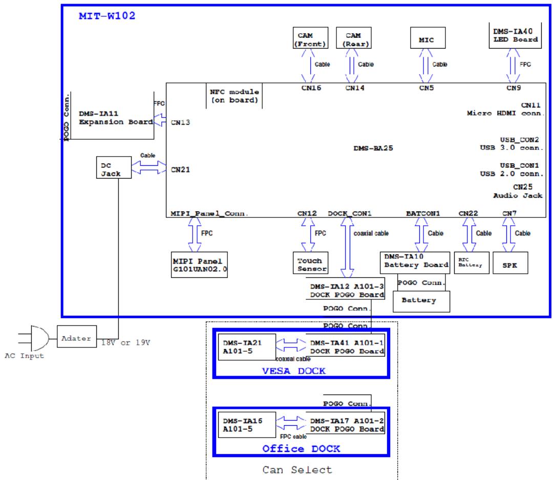
1.4 System Configuration
The block diagram of a MIT-W102 tablet computer is shown in the following diagram:
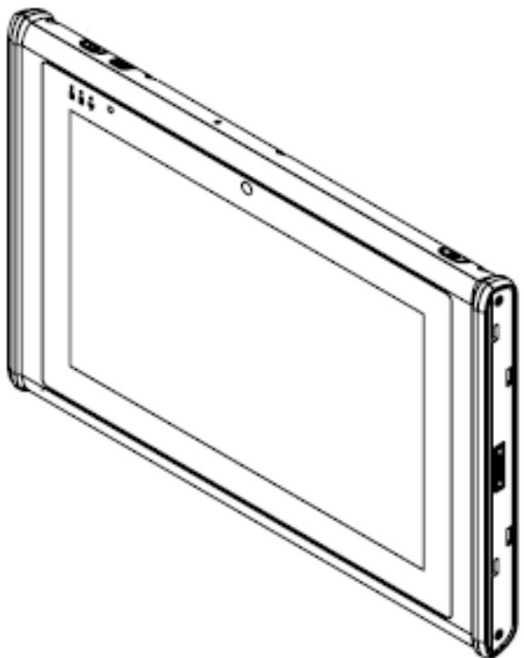
1.6 Exploring the MIT-W102
1.6.1 Front View
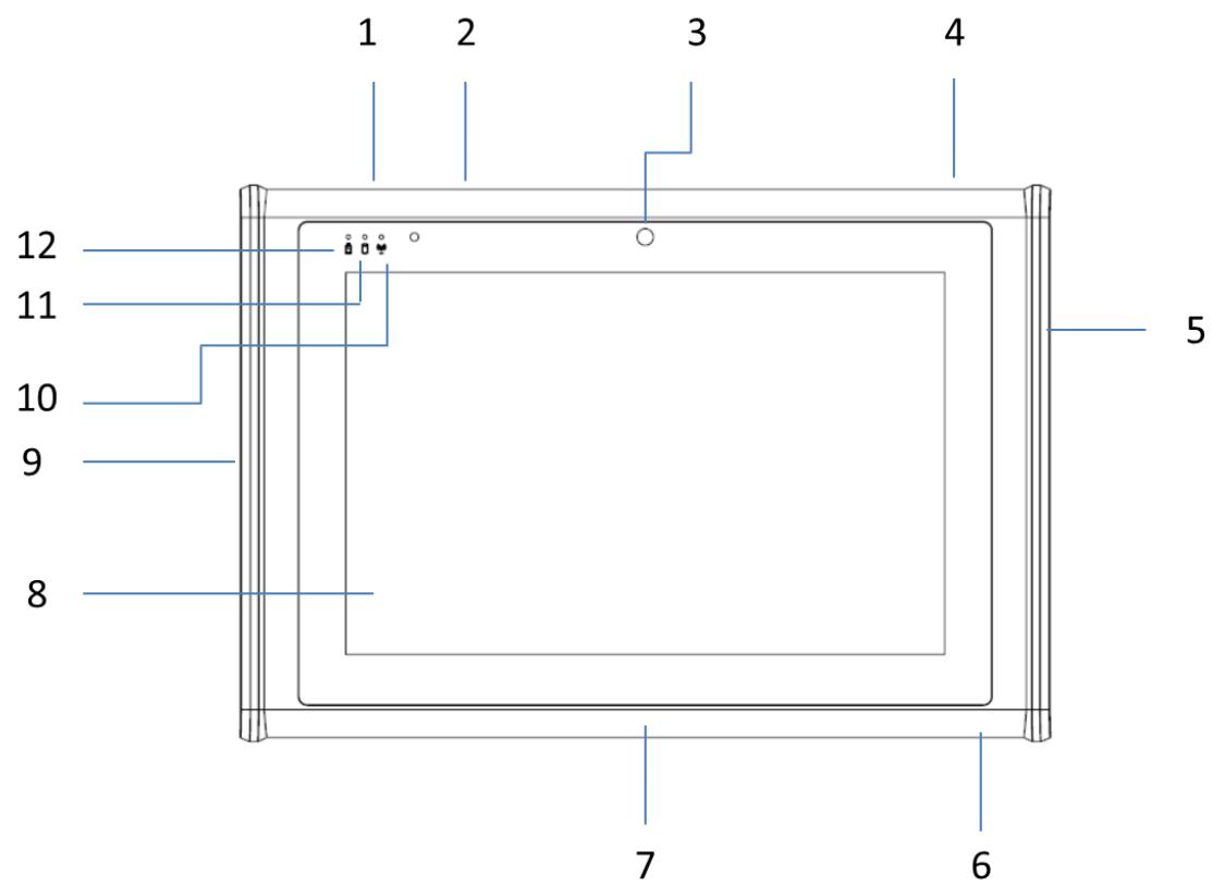
| No. | Component |
| 1 | P1 - Programmable Button |
| 2 | P2 - Programmable Button |
| 3 | Front Camera |
| 4 | Power button |
| 5 | Connected to expansion module |
| 6 | DC-in jack |
| 7 | Docking connector |
| 8 | Projective capacitive multiple touch screen |
| 9 | I/O ports • USB 3.0 x 1 • USB 2.0 x 1 • Micro HDMI x 1 |
| • Audio x 1 | |
| 10 | Connectivity LED indicator • Blue: when Wi-Fi / BT module is on |
| 11 | HDD LED indicator • Blinking green: when hard disk drive is working |
| 12 | Power / Battery LED indicator • Green: Battery is fully charged (>95%) • Amber: Battery is charging or Battery life is lower than 10% |
1.6.2 Rear View
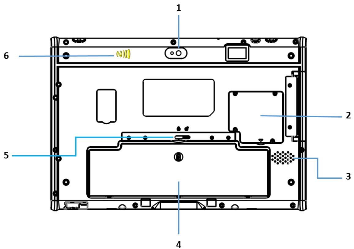
| No. | Component |
| 1 | Back camera |
| 3 | SSD cover |
| 4 | Speaker |
| 5 | Battery |
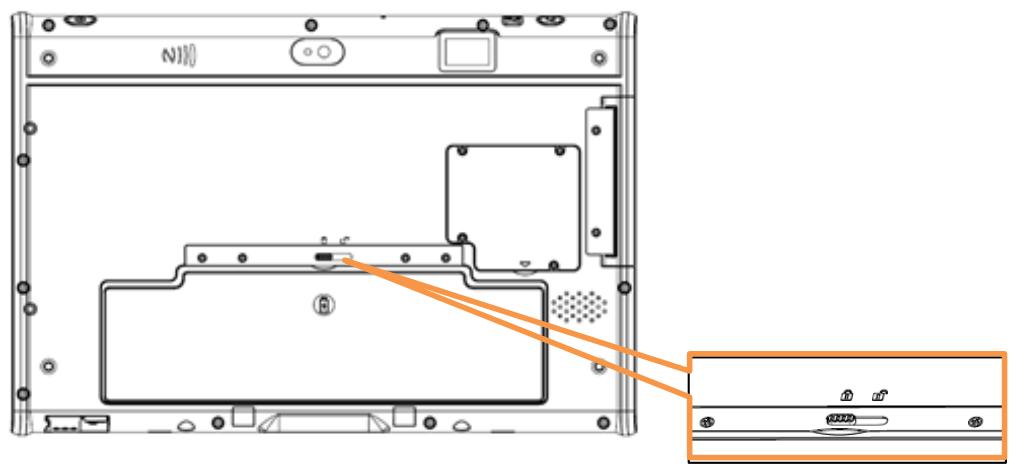
| 6 | Battery Latch |
| 7 | NFC |
1.6.3 Right View
| No. | Component |
| 1 | Connected pin for expansion module |
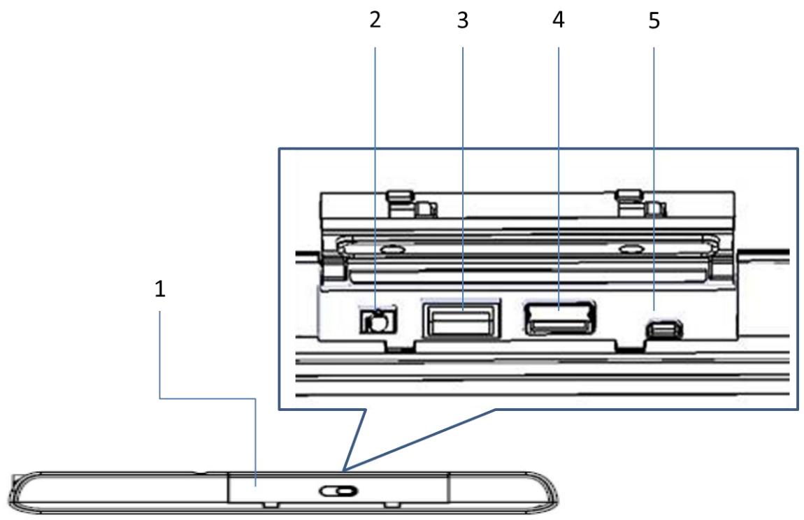
1.6.4 Left View
4
| No. | Component |
| 1 | I/O ports cover |
| 2 | Audio Jack |
| 3 | USB 3.0 |
| 4 | USB 2.0 |
| 5 | Micro HDMI |
1.6.5 Top View
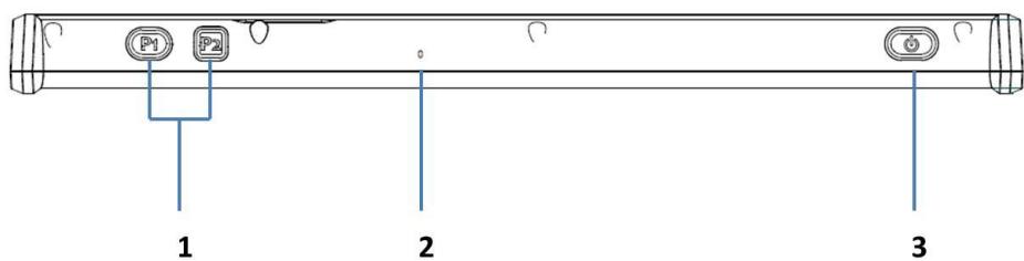
| No. | Component |
| 1 | Function buttons |
| 2 | Built-in MIC |
| 3 | Power button |
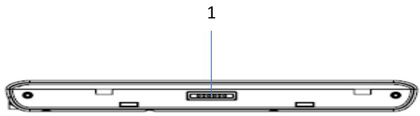
1.6.6 Bottom View
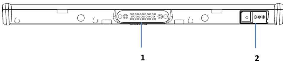
| No. | Component |
| 1 | Docking connector |
| 2 | AC-in jack |
Chapter 2 Making Connections
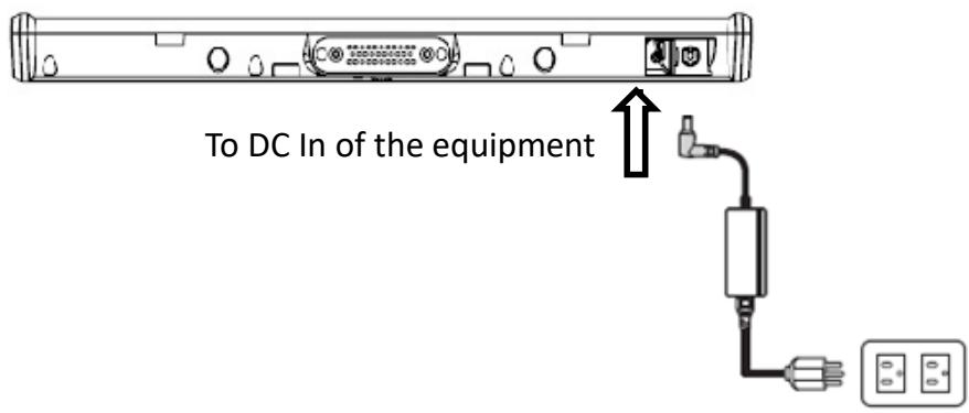
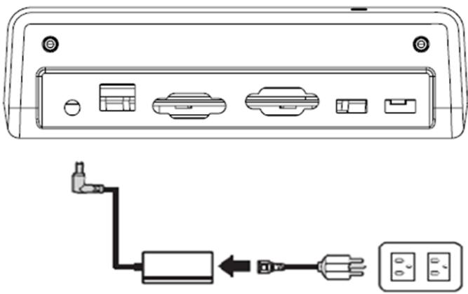
2.1 Connecting the Power
Before you can use your MIT-W102, you must fully charge the battery. Connect the power adapter as shown and leave to charge for:
- A minimum of 2 hours when using the internal battery
Condition: the operation time is based on the LCD backlight at 50% and the average utilization of the system under 10% .
Installation Procedures:
- Connect the female end of the power adapter to the DC-in of MIT-W102.
- Connect the female end of the power cord to the DC power adapter.
- Connect the 3-pin male plug of the power cord to an electrical outlet.
NOTE: Be sure always handle the power cords by holding the plug ends only.
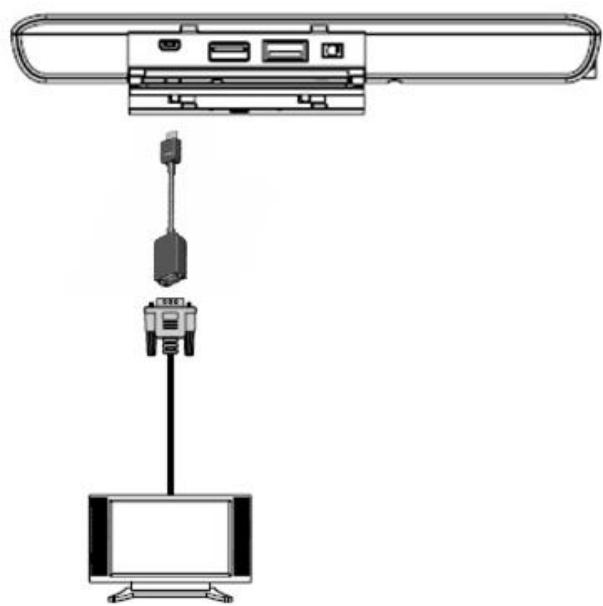
2.2 Connecting to a Monitor
You can connect the MIT-W102 to an external monitor for enhanced viewing.
Connect one end of a HDMI to VGA cable to the Micro HDMI port on the left side of the MIT-W102. Connect the other end to the VGA cable and connect to the monitor.
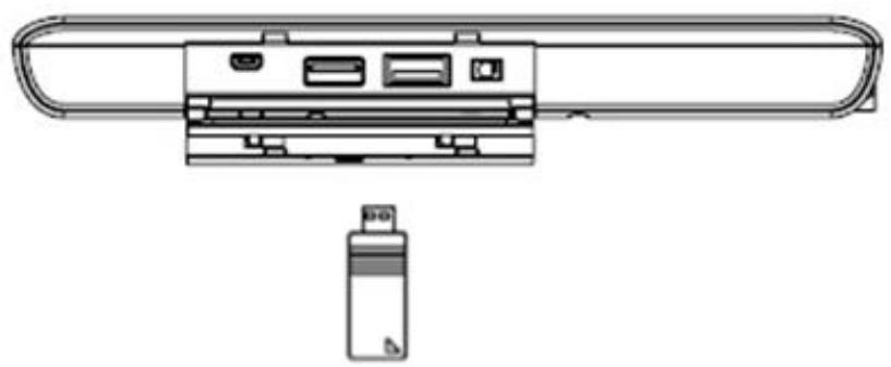
2.3 Connecting USB Devices
You can connect peripheral devices, such as a USB keyboard and mouse, as well as other wireless devices using the USB ports on the left side of the MIT-W102.
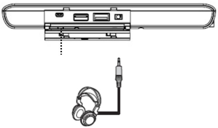
2.4 Connecting Headphones
You can connect a pair of headphones using the headphone jack on the left side of the MIT-W102.
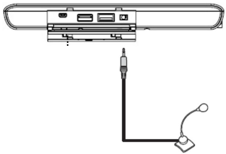
2.5 Connecting a Microphone
The MIT-W102 features a built-in microphone, but you can still connect an external microphone if needed. Connect the microphone to the microphone jack on the left side of the MIT-W102 as shown.
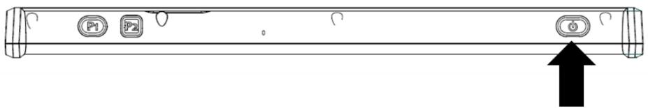
Chapter 3 Turning On
- Press and hold the power button to turn on the MIT-W102.
3.1 Controlling the MIT-W102
3.1.1 Using the Touch Screen
The MIT-W102 is equipped with touch screen technology, for ease of use when you are on the go. Simply tap the screen with your finger to select icons and run applications.
3.1.2 Using the Tap Function
When you tap on the screen with a pen or stylus, it emulates click functions of a regular mouse.
- To emulate a left click single tap the screen once.
- To emulate a right click tap and hold the screen.
- To emulate a double click, tap the screen twice.
3.1.3 Using the Control Panel Buttons
The control panel buttons are located on the top side of MIT-W102.
See below for a description of the two buttons and its function.
| Button | Name | Function |
| P1 P2 | Function | Press to access your favorite programs |
| Power | Press to power on/off |
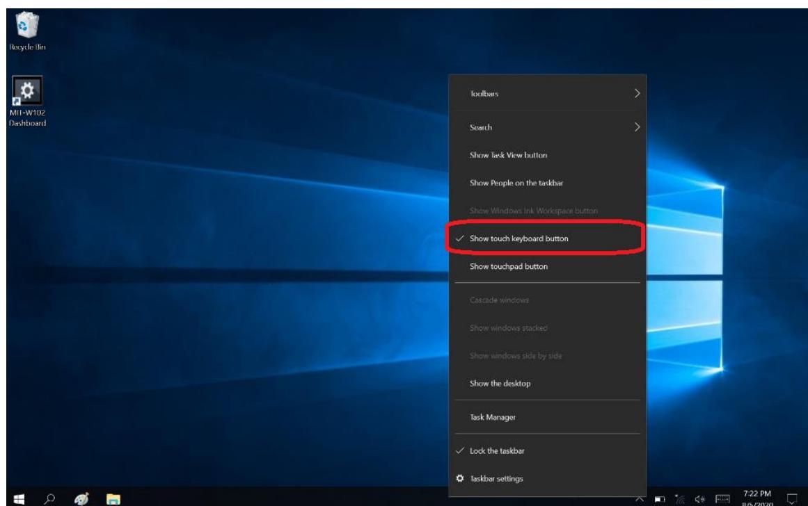
3.1.4 Using the On-Screen Keyboard
- Press and hold on the taskbar.
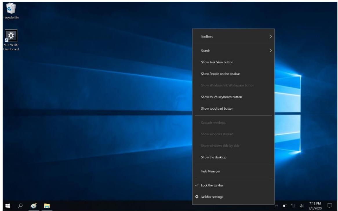
- Enable "show touch keyboard button"
3. Tap the icon on the taskbar to open the keyboard
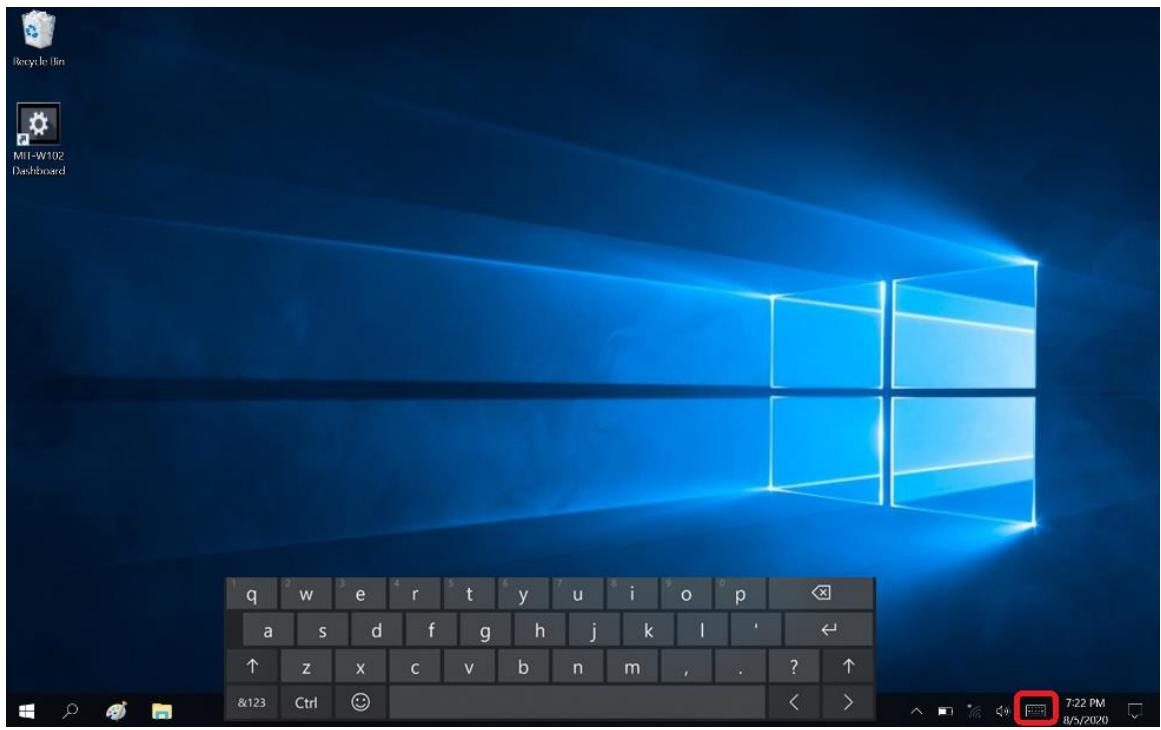
4. Use your finger or stylus pen to tap and enter letters, numbers and symbols as you would with a regular keyboard. To type capital letters tap the lock icon on the on-screen keyboard.

a. To use handwriting, tap upper left button of On-Screen Keyboard.
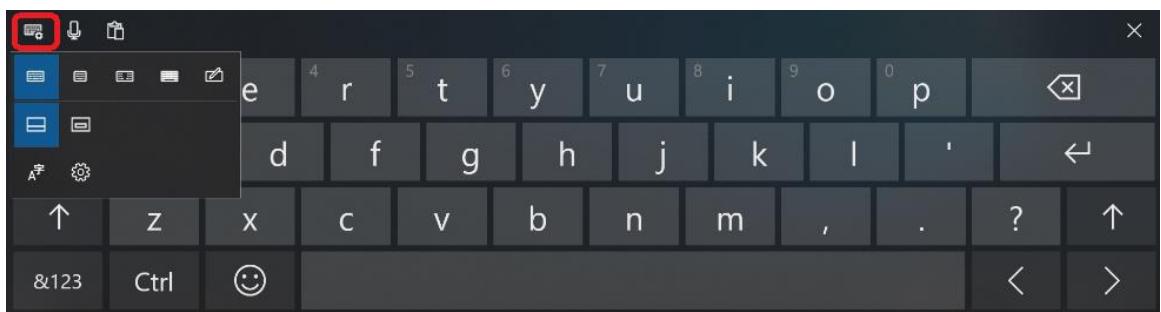
b. Select the handwriting icon.
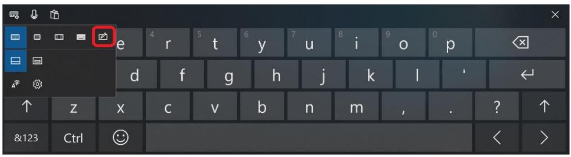
c. Use your finger and stylus pen to write on screen.

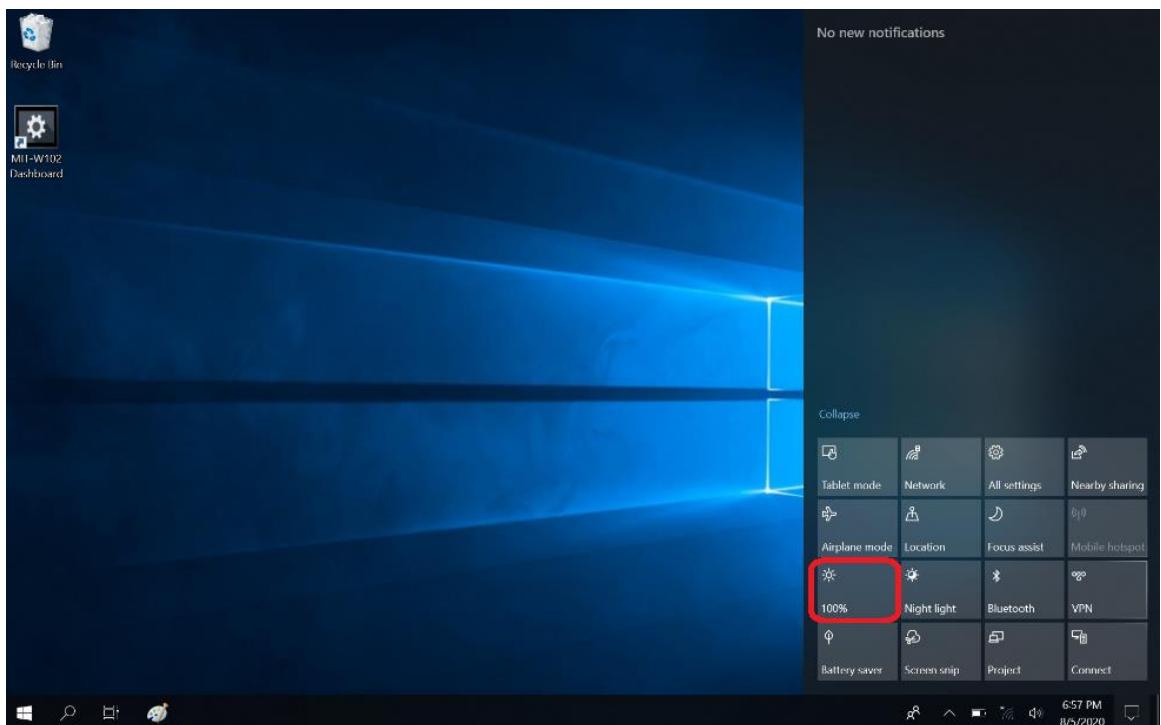
3.1.5 Adjusting Screen Brightness
- Tap on the right end of the taskbar to open the Action Center
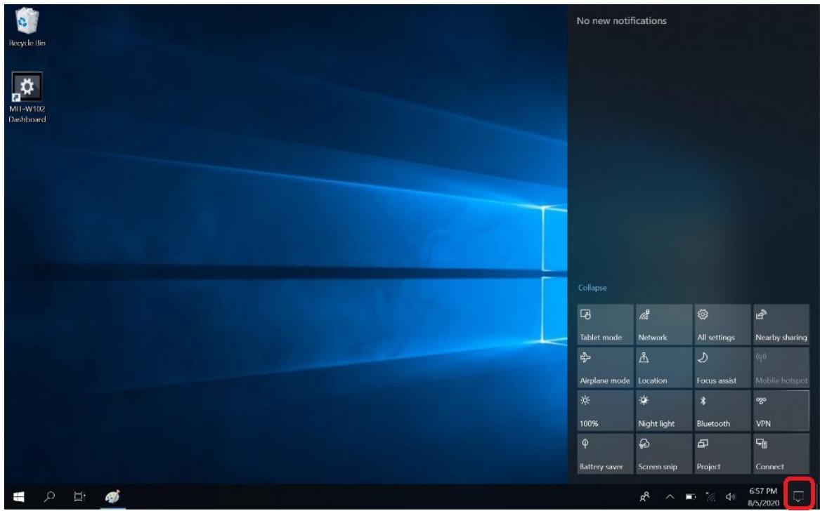
- Tap Brightness icon to adjust the brightness.
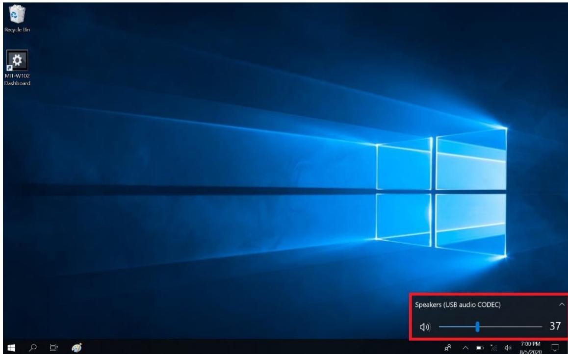
3.1.6 Adjusting the Volume
1. Tap the Volume icon on taskbar
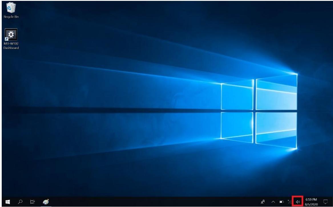
2. Move the slide to adjust volume to tap the icon to mute
Chapter 4 Wireless Connections
4.1 Wi-Fi Connection
| Note | Wi-Fi access requires a separate purchase of a service contract with a wireless service provider. Contact a wireless service provider for more information. |
The MIT-W102 comes pre-loaded with WLAN module; you can send and receive signals to a Wi-Fi network then synchronize files.
A wireless network can be added either when the network is detected or by manually entering settings information. Before doing these steps, determine if authentication information is needed.
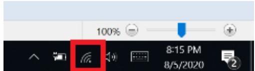
- Click the wireless connection icon on the taskbar
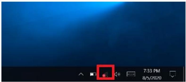
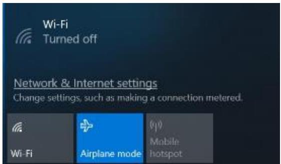
- Turn on Wi-Fi by tapping the icon
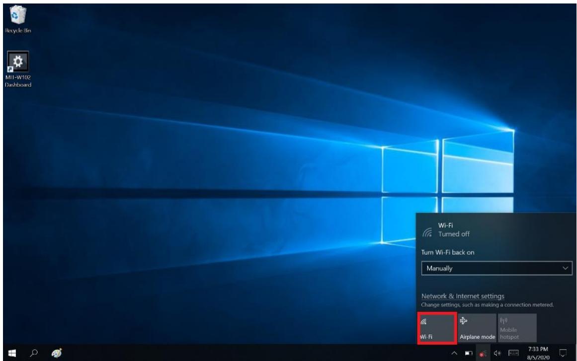
- Available wireless access points will be shown once Wi-Fi is enabled.
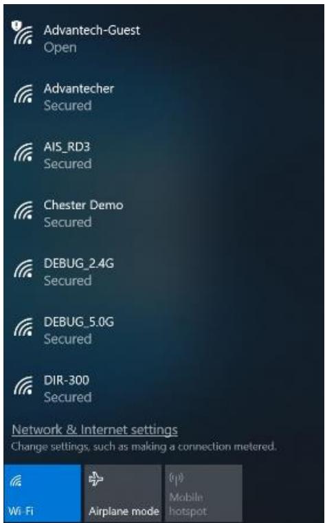
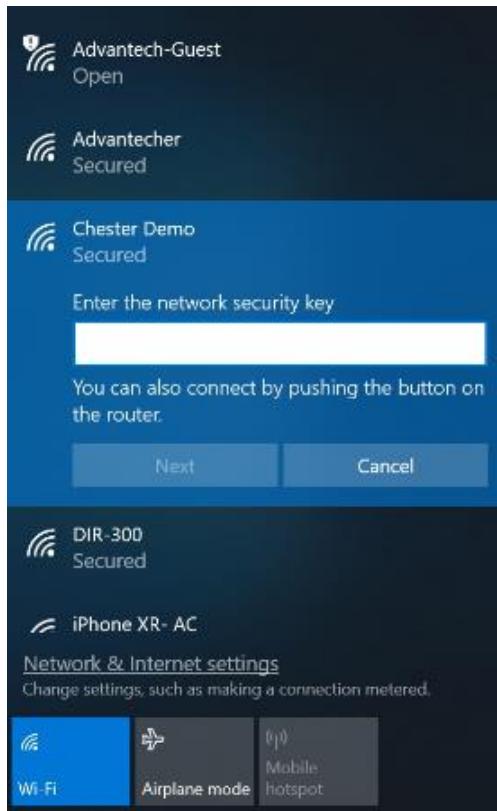
- Select the access point to connect with.
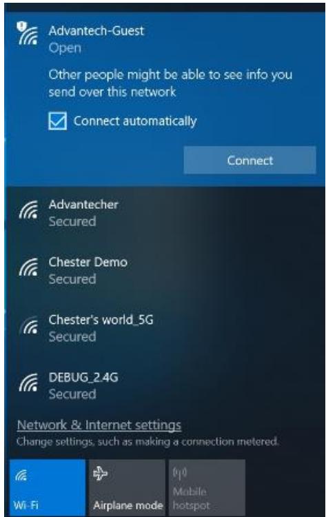
- You may be prompted to enter a Security key for secure access.
- The wireless connection is negotiated and the icon in the notification area shows a connected status whenever a wireless connection is present.
- Airplane mode can be enabled to turn off Wi-Fi
4.2 Bluetooth Connections
The MIT-W102 comes with built-in Bluetooth functionality that allows you to connect and communicate with other Bluetooth-enabled devices.
4.2.1 Setting Up Bluetooth
Follow these instructions to set up a Bluetooth connection.
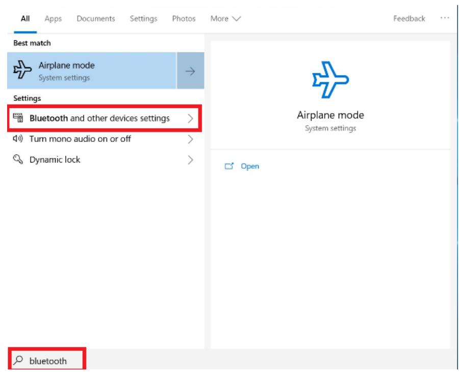
- Type Bluetooth in Search and tap "Bluetooth and other devices settings"
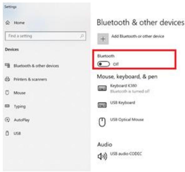
- Slide the icon to enable Bluetooth
3. When enabled, Bluetooth icon will be shown on the taskbar
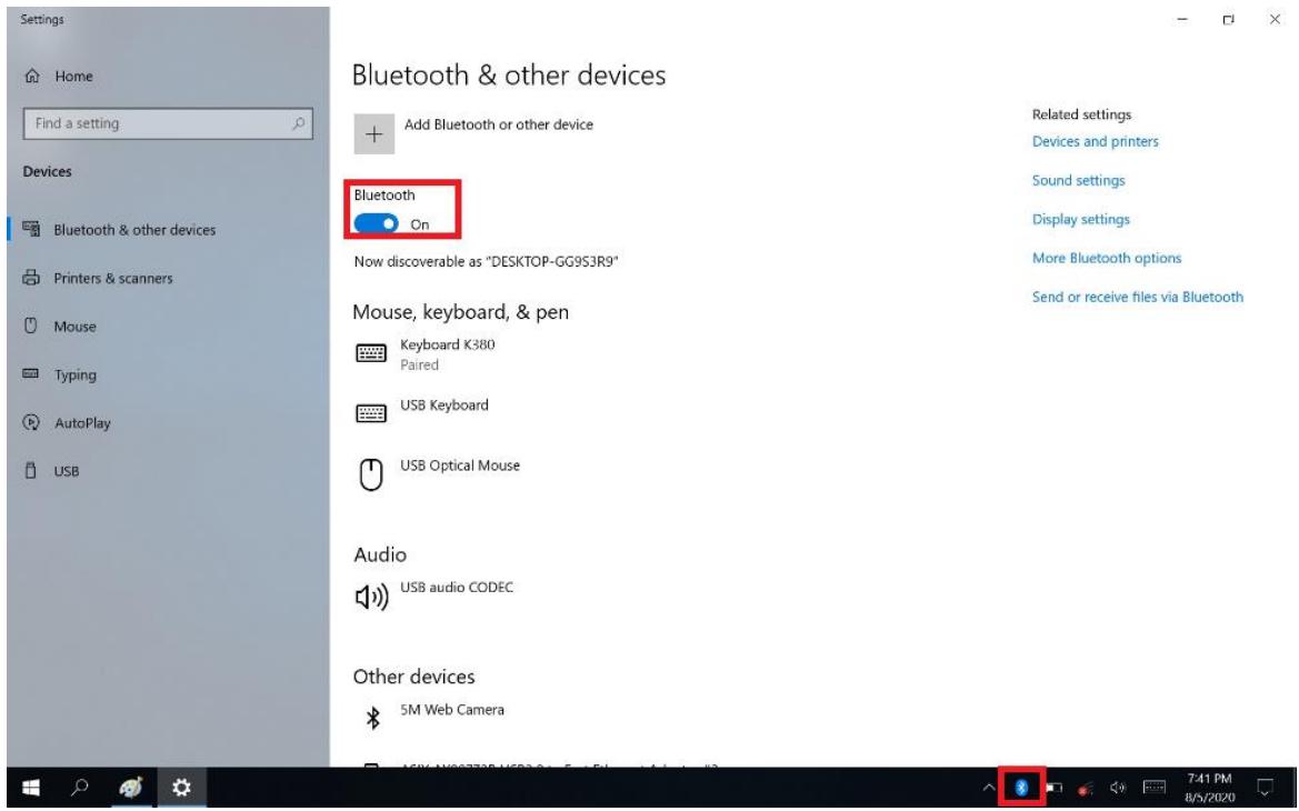
4. Add more Bluetooth device by clicking on the icon “+”
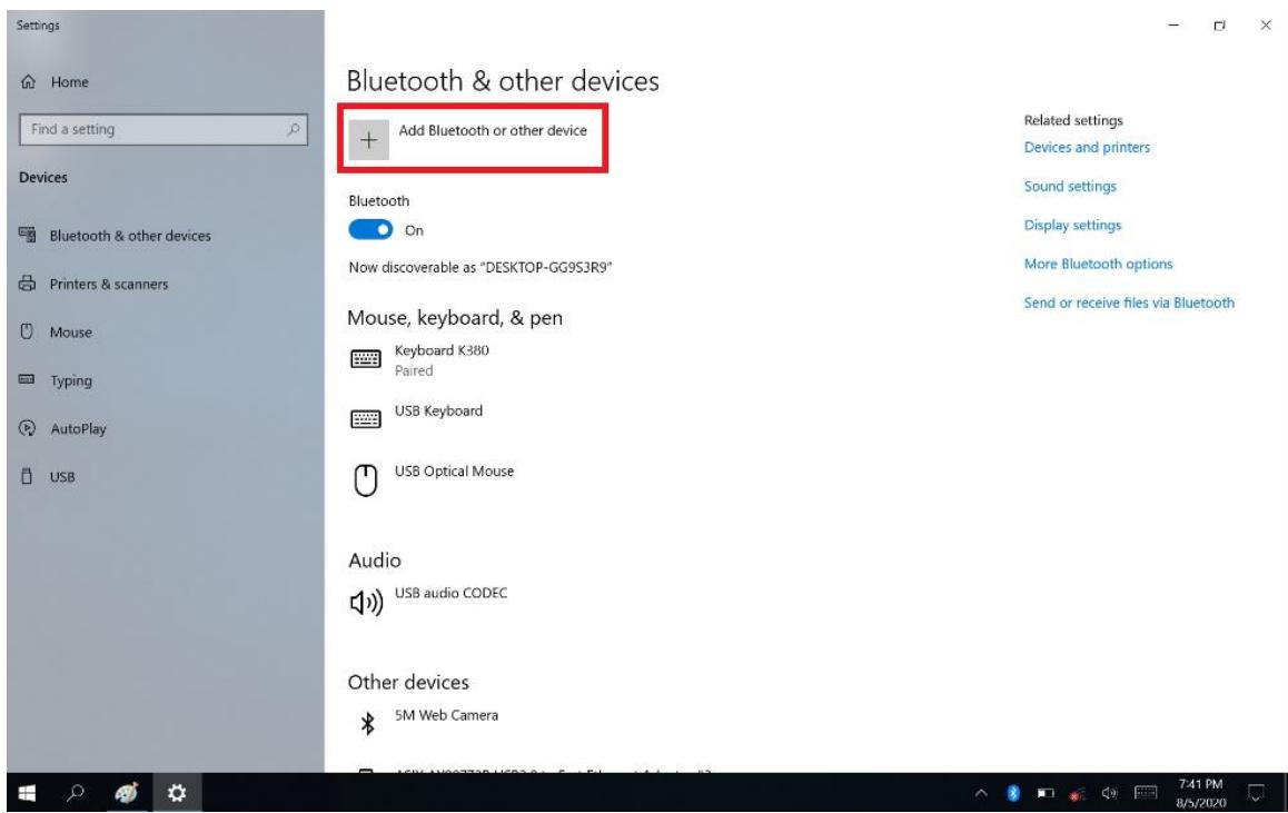
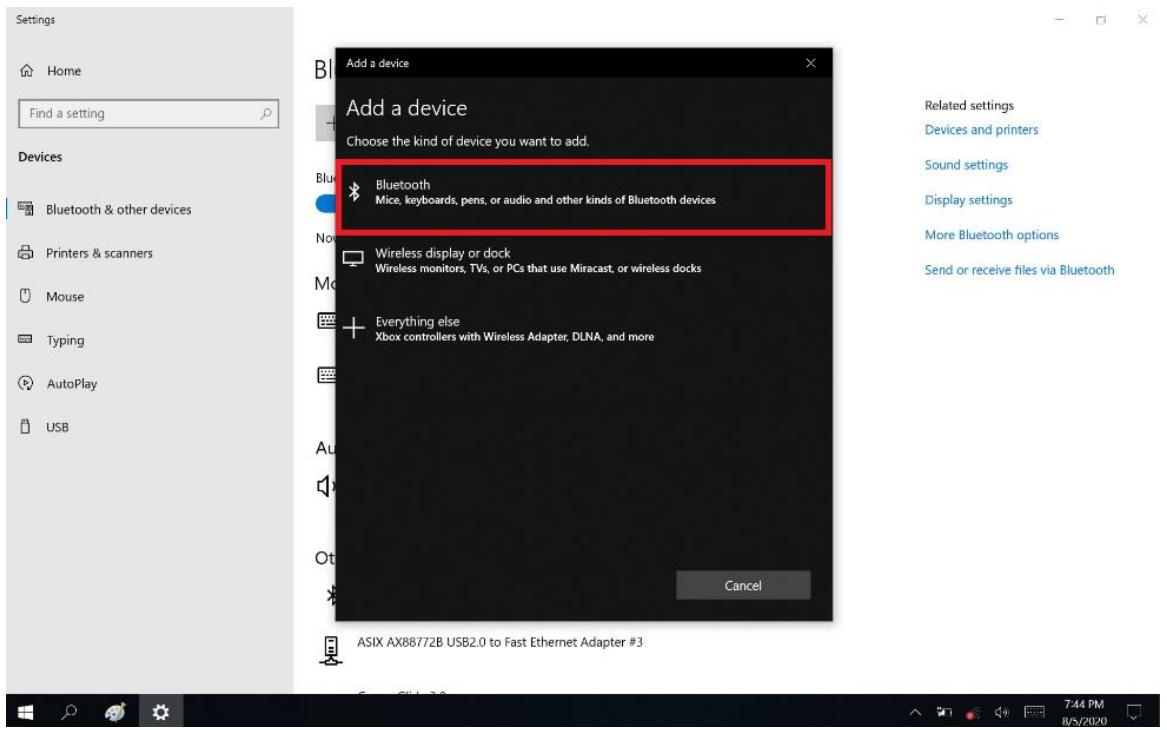
5. Select "Bluetooth"
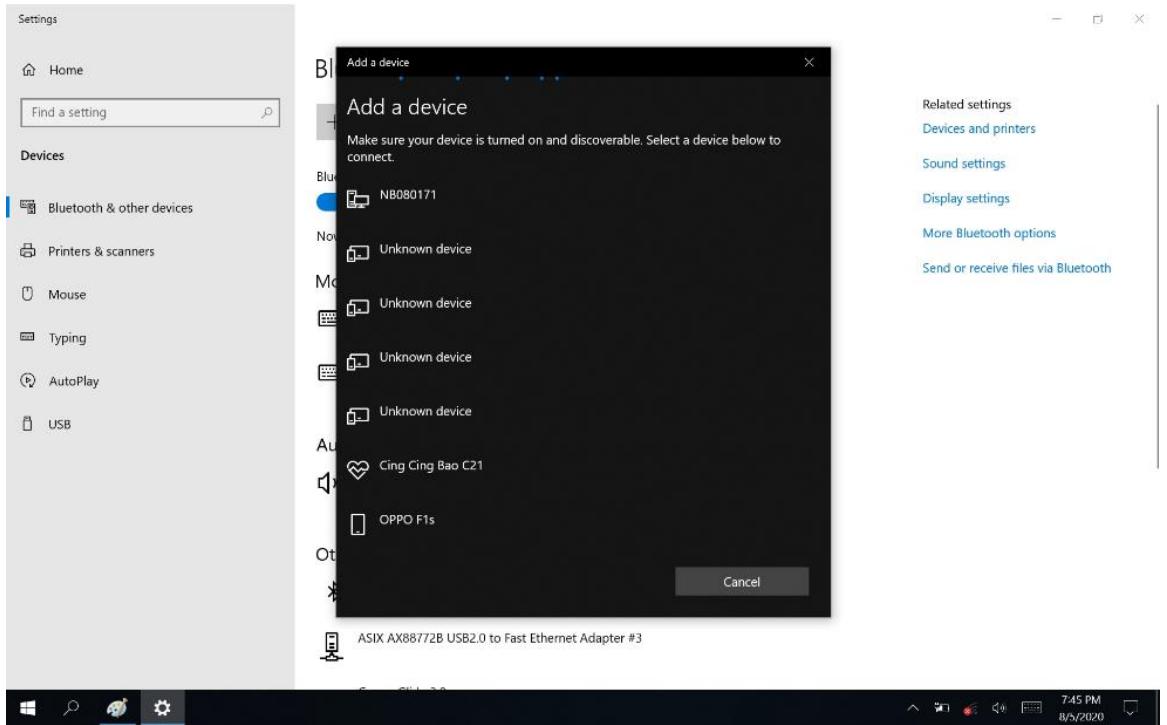
6. Select the Bluetooth device to connect from the available device menu
- Comparing MIT-W102 with the Bluetooth device with Pass Key Entered
- The Bluetooth device is successfully connected with MIT-W102 when the process is completed.
It is recommended that you use a passkey to prevent unauthorized access to your MIT-W102.
Chapter 5 Advance Setting
5.1 Checking Battery Status
As it is likely you will be using your MIT-W102 when out and about, it is important that you monitor the battery status regularly, to ensure you do not run out of power at a critical moment.
- Tap on the Power icon on the taskbar to view detailed information and the battery screen appears.
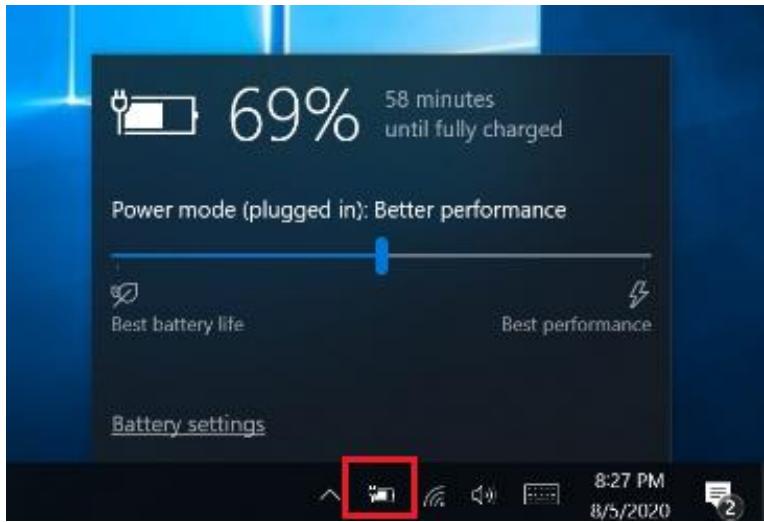
Best performance - Favors performance over power
Best battery life - Saves energy by reducing MIT-W102's performance.
5.2 Maintenance
- If encounter any of system failure or serious incident in relation to device, please report to the manufacturer or local agent.
5.2.1 Maintaining the Battery
- Do not expose heat or attempt to disassemble the battery, and do not place the battery in water or in a fire.
- Do not subject the battery to strong impact, such as a blow from a hammer, or stepping on or dropping it.
- Do not puncture or disassemble the battery.
- Do not attempt to open or service the battery.
-
Replace only with batteries designed specifically for this product.
-
Keep the battery out of reach of children.
- Dispose of used batteries according to local regulations.
5.2.2 Maintaining the LCD Display
- Do not scratch the surface of the screen with any hard objects.
- Do not spray liquid directly on the screen or allow excess liquid to drip down inside the device.
- Do not place anything, such as food and drink, on the screen at any time to prevent damage to the screen.
- Clean the LCD display only with a soft cloth dampened with 60% above isopropyl alcohol or 60% above ethyl alcohol each time after use.
5.2.3 Cleaning the MIT-W102
- Turn off the MIT-W102 and unplug the power cord.
- Wipe the screen and exterior with a soft, damp cloth moistened only with water. Do not use liquid or aerosol cleaners on the screen, as these will discolor the finish and damage the screen.
5.3 Trouble Shooting
When System behaves abnormally, such as
- Failure to power on.
- Failure to power off.
- Power on LED off but DC power plug in.
- Any other LEDs ON but system cannot work.
Contact your distributor, sales representative, or Advantech's customer service center for technical support if you need additional assistance. Please have the following information ready before you call:
Product name and serial number.
- Descriptions of your peripheral attachments.
- Descriptions of your software (operating system, version, application software, etc.)
A complete description of the problem.
The exact wording of any error messages.
| Guidance and manufacturer's declaration – electromagnetic emissions | ||
| The model MIT-W102 SERIES is intended for use in the electromagnetic environment specified below. The customer or the user of the model MIT-W102 SERIES should assure that it is used in such an environment. | ||
| Emissions test | Compliance | Electromagnetic environment – guidance |
| RF emissions | The model MIT-W102 SERIES uses RF energy only for its internal function. Therefore, its RF emissions are very low and are not likely to cause any interference in nearby electronic equipment. | |
| CISPR 11 | ||
| RF emissions | The model MIT-W102 SERIES is suitable for use in all establishments, including domestic establishments and those directly connected to the public low-voltage power supply network that supplies buildings used for domestic purposes. | |
| CISPR 11 | ||
| Harmonic emissions | ||
| IEC 61000-3-2 | ||
| Voltage fluctuations/flicker emissions | ||
| IEC 61000-3-3 | ||
| Recommended separation distances between portable and mobile RF communications equipment and the model MIT-W102 Series | |||
| The model MIT-W102 series is intended for use in an electromagnetic environment in which radiated RF disturbances are controlled. The customer or the user of the model MIT-W102 series can help prevent electromagnetic interference by maintaining a minimum distance between portable and mobile RF communications equipment (transmitters) and the model MIT-W102 series as recommended below, according to the maximum output power of the communications equipment. | |||
| Rated maximum output power of transmitterW | Separation distance according to frequency of transmitterm | ||
| 150 kHz to 80 MHzd = 1,2√P | 80 MHz to 800 MHzd = 1,2√P | 800 MHz to 2,5 GHzd = 2,3√P | |
| 0,01 | 0,12 | 0,12 | 0,23 |
| 0,1 | 0,38 | 0,38 | 0,73 |
| 1 | 1,2 | 1,2 | 2,3 |
| 10 | 3,8 | 3,8 | 7,3 |
| 100 | 12 | 12 | 23 |
| For transmitters rated at a maximum output power not listed above, the recommended separation distance d in metres (m) can be estimated using the equation applicable to the frequency of the transmitter, where P is the maximum output power rating of the transmitter in watts (W) according to the transmitter manufacturer. NOTE 1 At 80 MHz and 800 MHz, the separation distance for the higher frequency range applies. NOTE 2 These guidelines may not apply in all situations. Electromagnetic propagation is affected by absorption and reflection from structures, objects and people. | |||
| Guidance and manufacturer's declaration - electromagnetic immunity | |||
| The model MIT-W102 SERIES is intended for use in the electromagnetic environment specified below. The customer or the user of the model MIT-W102 SERIES should assure that it is used in such an environment. | |||
| Immunity test | IEC 60601 test level | Compliance level | Electromagnetic environment - guidance |
| Conducted RF | 3 | Portable and mobile RF communications equipment should be used no closer to any part of the model MIT-W102 SERIES, including cables, than the recommended separation distance calculated from the equation applicable to the frequency of the transmitter. Recommended separation distance | |
| IEC 61000-4-6 | Vrms | d = 1,2√P | |
| 150 | Vrms | ||
| kHz | |||
| Radiated RF | to 80 | d = 1,2√P 80 MHz to 800 MHz | |
| IEC 61000-4-3 | MHz | d = 2,3√P 800 MHz to 2,5 GHz | |
| V/m | |||
| 3 V/m | |||
| 80 | where P is the maximum output power rating of the transmitter in watts (W) according to the transmitter manufacturer and d is the recommended separation distance in meters (m). | ||
| MHz to 2,5 GHz | |||
Field strengths from fixed RF transmitters, as determined by an electromagnetic site survey, ^a should be less than the compliance level in each frequency range. ^b
Interference may occur in the vicinity of equipment marked with the following symbol:

NOTE 1 At 80MHz and 800MHz , the higher frequency range applies.
NOTE 2 These guidelines may not apply in all situations. Electromagnetic propagation is affected by absorption and reflection from structures, objects and people.
Field strengths from fixed transmitters, such as base stations for radio (cellular/cordless) telephones and land mobile radios, amateur radio, AM and FM radio broadcast and TV broadcast cannot be predicted theoretically with accuracy. To assess the electromagnetic environment due to fixed RF transmitters, an electromagnetic site survey should be considered. If the measured field strength in the location in which the model MIT-W102 SERIES is used exceeds the applicable RF compliance level above, the model MIT-W102 SERIES should be observed to verify normal operation. If abnormal performance is observed, additional measures may be necessary, such as reorienting or relocating the model MIT-W102 SERIES.
b Over the frequency range 150kHz to 80MHz , field strengths should be less than V / m .
Chapter 6 Dashboard and Hotkey setting
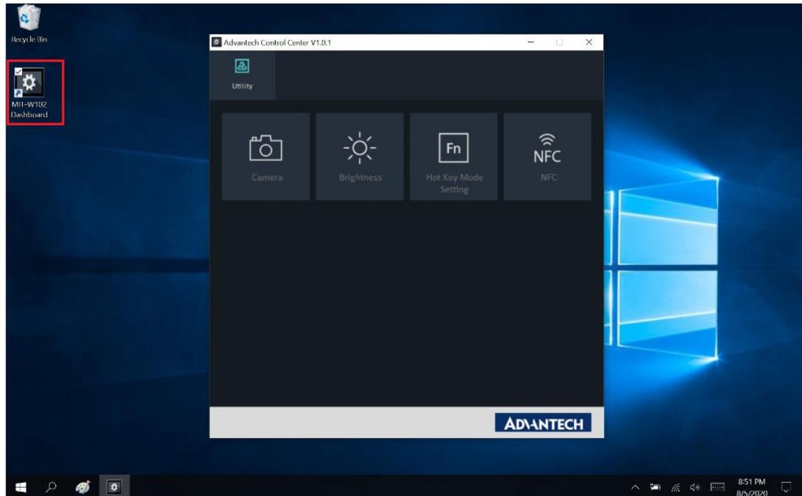
6.1 Dashboard
Click on the shortcut to launch the dashboard
6.2 NFC
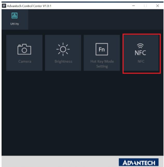
6.2.1 NFC application
Click NFC icon to launch the application
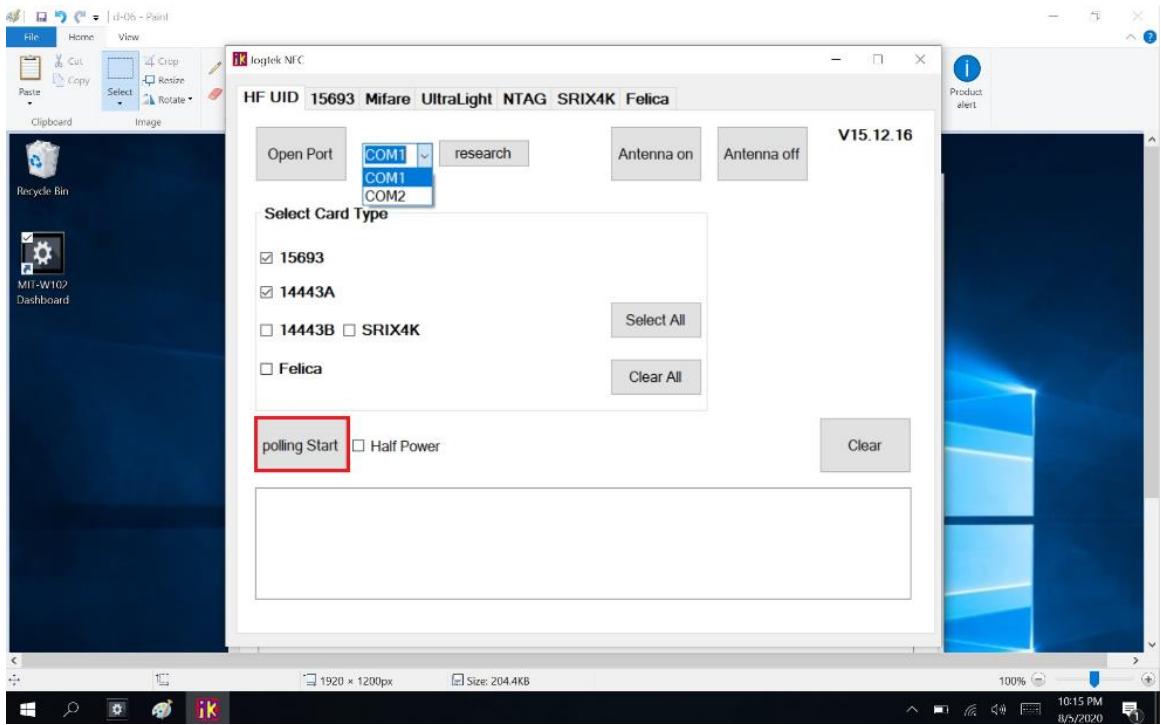
6.2.2 NFC Setting
(1) Select COM port number 2
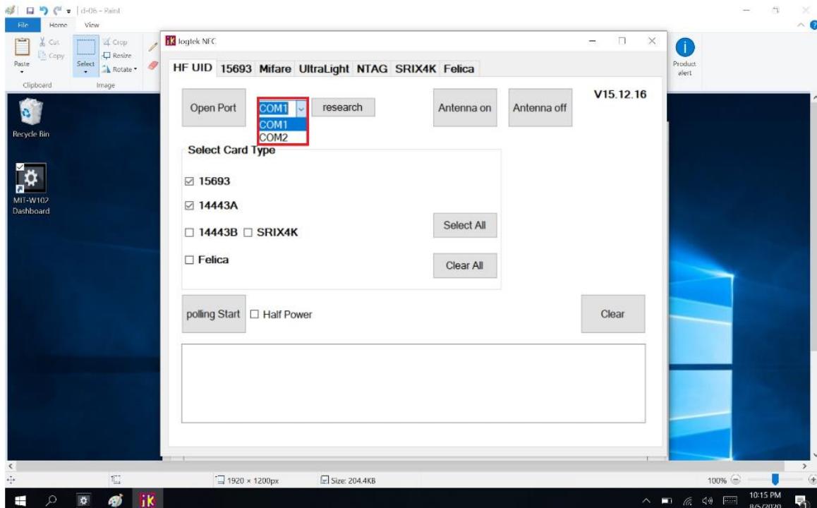
(2) Open Port
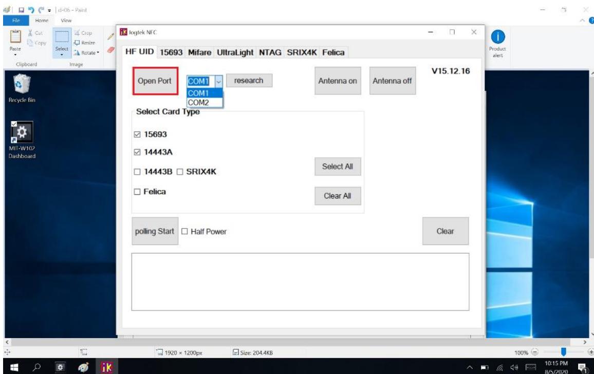
(3) Select Card Type
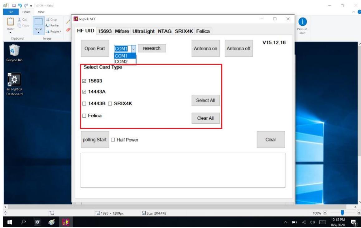
(4) Polling Start
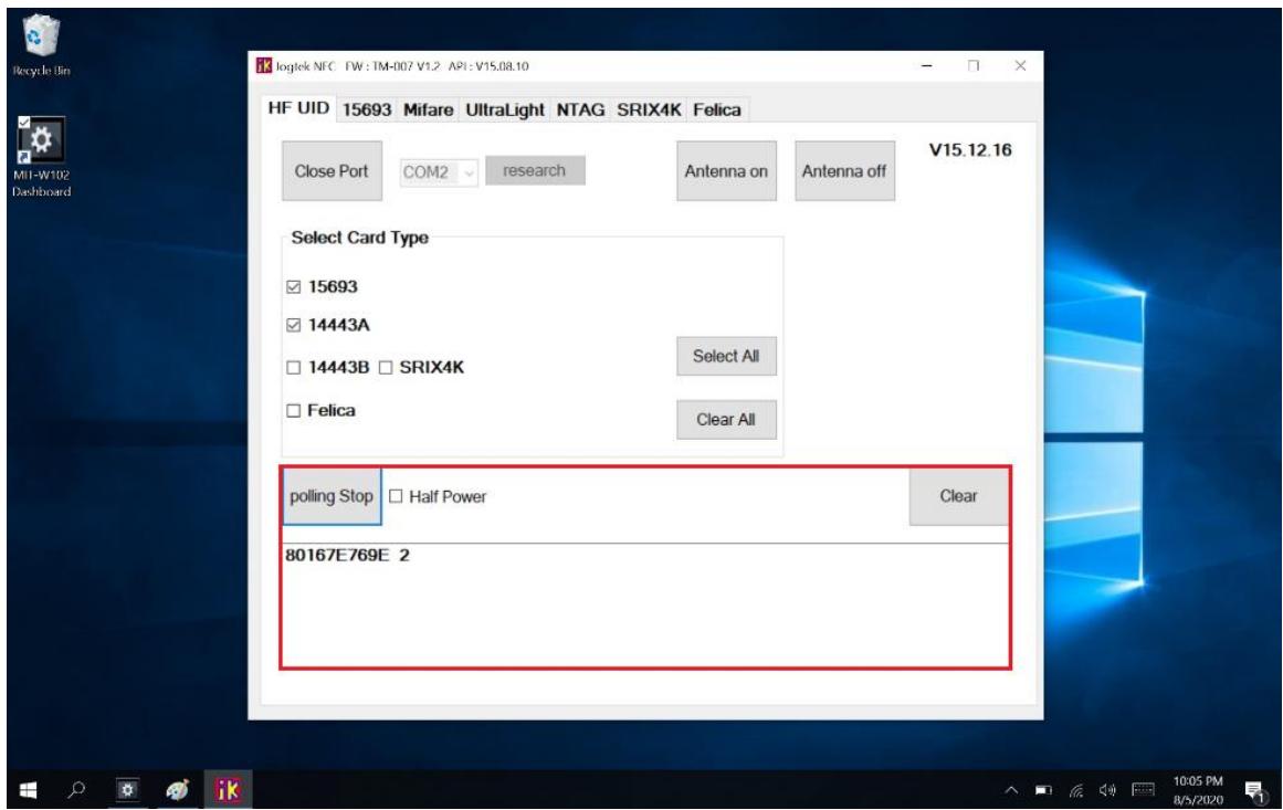
6.2.3 NFC Usage
NFC card can be detected when approaching the right hand side of the device
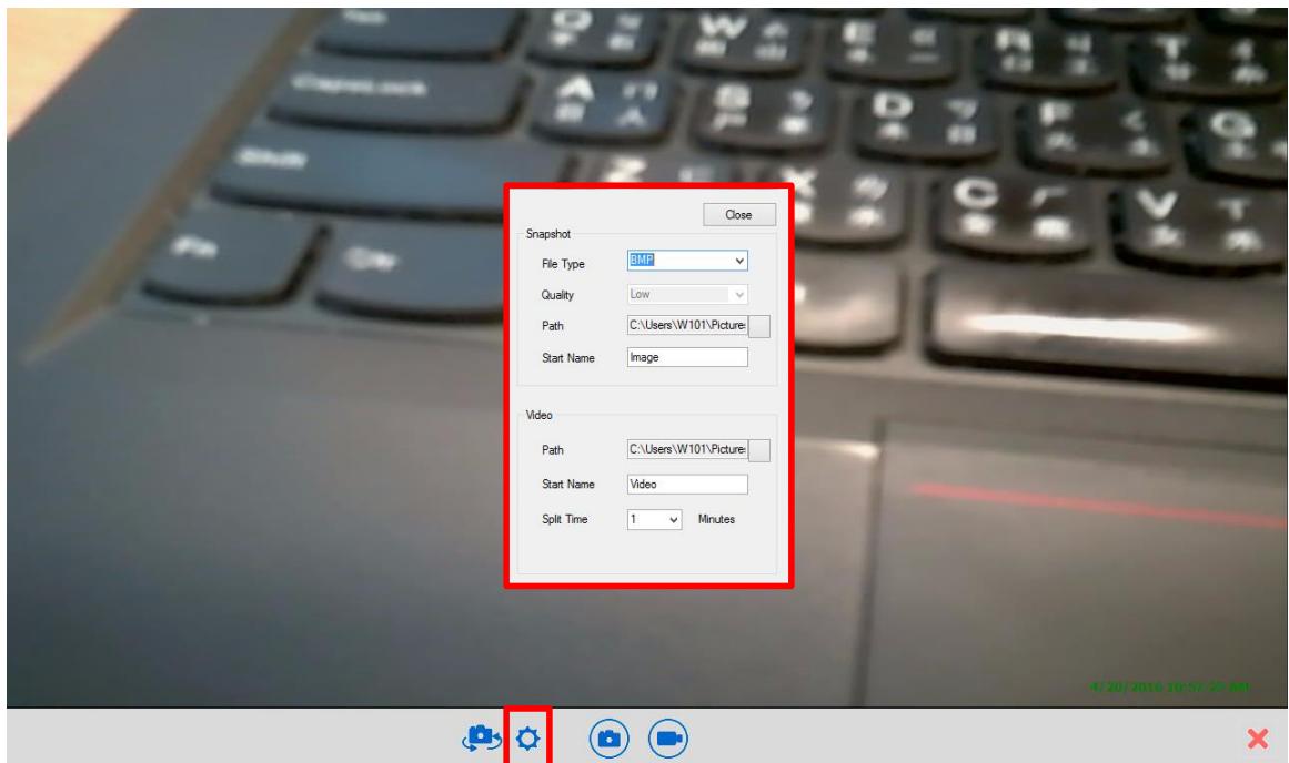
6.3 camera
(1) Click Camera icon
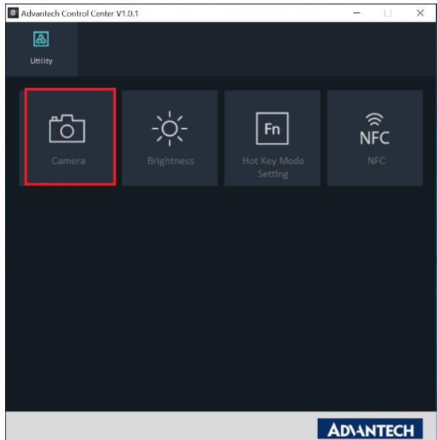
(2) Default Rear Camera mode on the UI
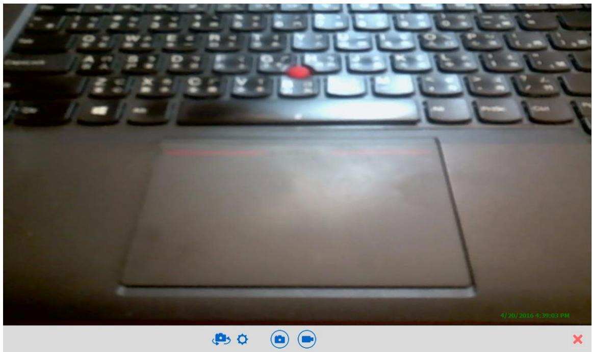
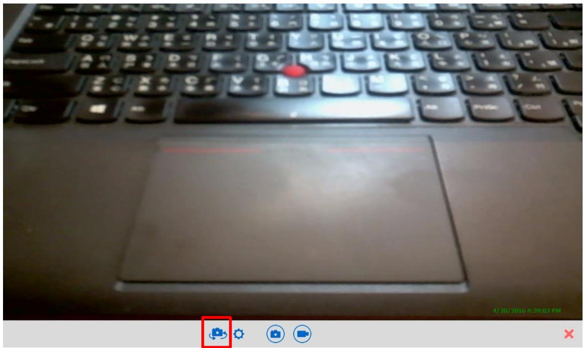
(3) Switch Front / Rear Camera (Click camera icon to switch camera)
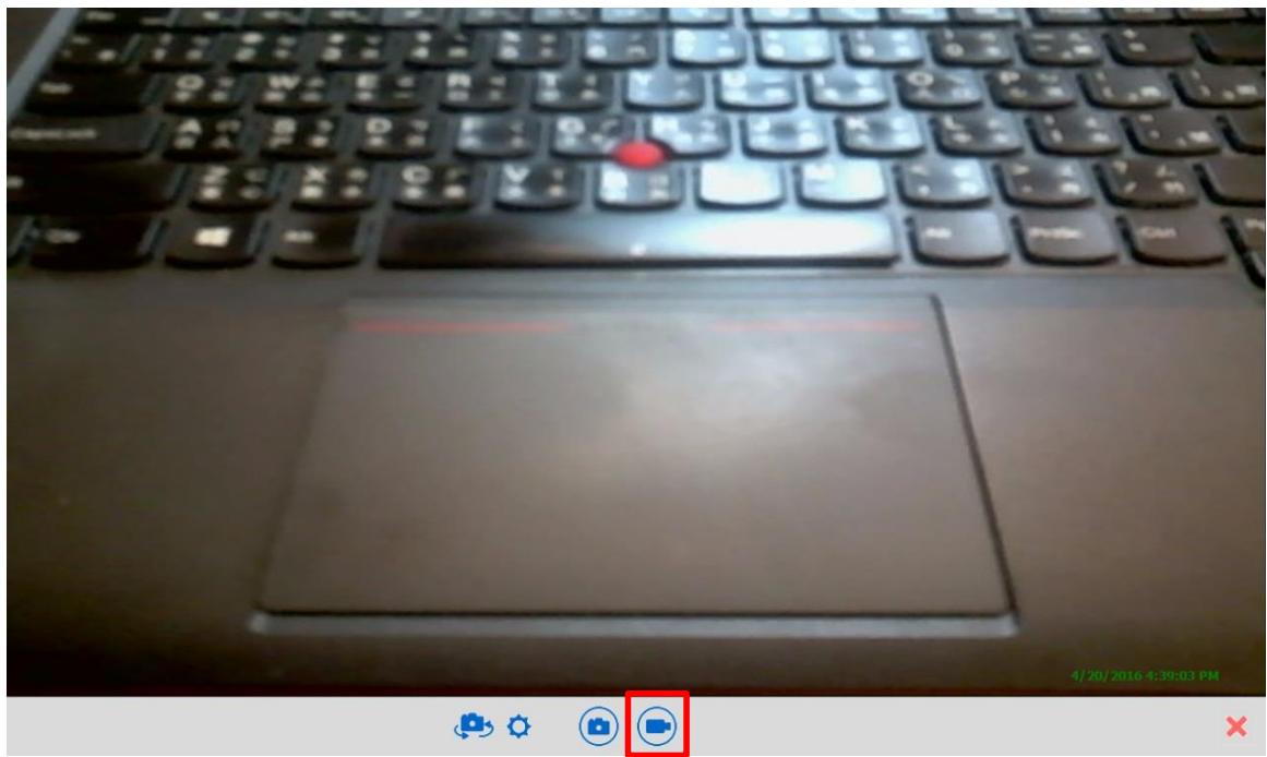
(4) Video Recording . Click video icon
(5) Click setting icon to change file name and path.
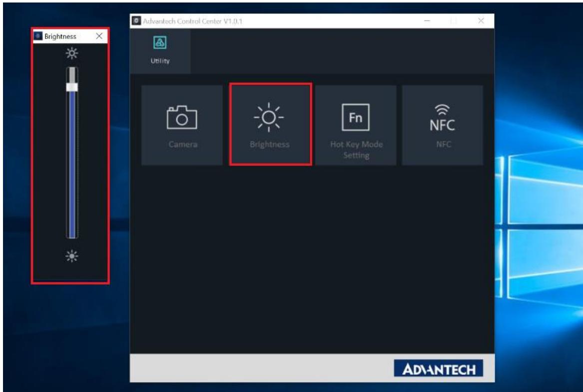
6.4 Brightness
Click Brightness icon to adjust brightness
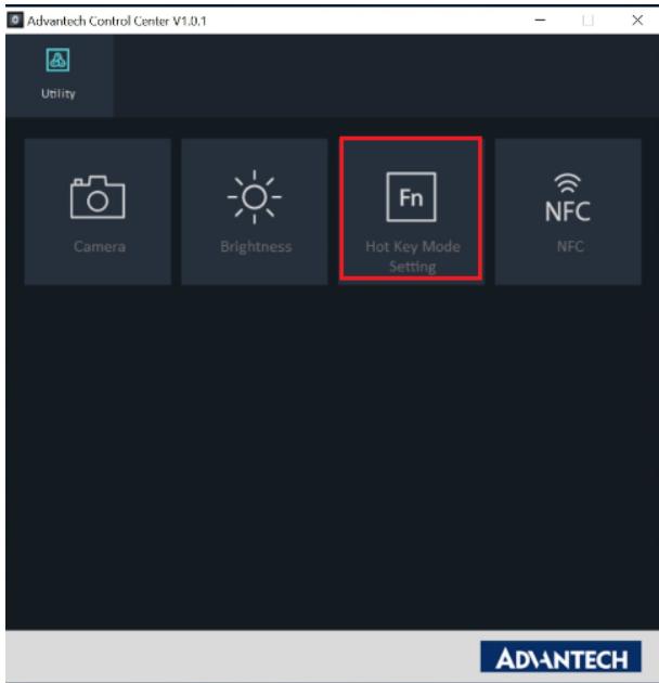
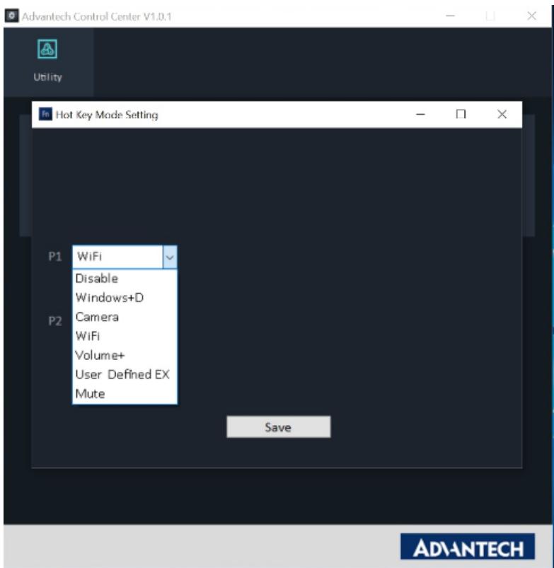
6.5 Hotkey Setting
Click Hot Key Mode Setting and select function.
E.g.: Set P1 key as WiFi ON / OFF key.
Appendix Specifications
A.1 Specifications
| Feature | Description |
| Operating System | Microsoft Windows 10 IoT Enterprise LTSC |
| Processor | Intel® Pentium® Processor N4200 |
| Max. speed | Quad Core 1.1GHz (Burst Frequency : 2.5GHz) |
| Memory | LPDDR4 1600MHz 4GB on board memory |
| Storage | 1 x m.2 SSD (Default 64GB / supports up to 128GB) |
| Display | 10.1” WUXGA TFT LCD |
| Touch Panel | P-CAP Multiple Touch |
| Application Button | One Power button Two Function programmable buttons for quick selection of applications |
| Communication | 802.11a/b/g/n/ac WLAN built-in with integrated antenna Bluetooth V5.0,V4.2, V4.1, V4.0 LE, V3.0+HS, Bluetooth V2.1+EDR system built-in with integrated antenna |
| Camera | 2.0M Fixed Focus Camera at front 5.0M Auto Focus Camera with Flash LED at rear |
| Main Battery | Rechargeable Li-ion battery (Advantech MIT101-BATC) Standard battery, 11.1V, 2860 mAh, 3S2P |
| Medical Power Adapter | AC Adapter: AC 100V-250V 50/60Hz,1.5A(max) Output : 19Vdc/3.15A(max)/60W, Auto Sensing/Switching worldwide power supply |
| Security | 1. Password security 2. TPM 2.0 |
| I/O Ports | One USB 3.0/ 2.0 One USB 2.0 One HP/MIC combined jack One Micro HDMI type D One DC-in jack One Expansion port 8-pin One Docking port 32-pin |
| Audio Output | One 1 watt speaker |
| Physical | 295 x 196 x 20mm Approx. 1.1Kg (base configuration); approx. 2.43lbs |
| Environment | Operational altitude: 3000 meters (700-1060hPa) Storage/Transportation altitude: 5000 meters (500-1060hPa) Operating Temperature:0°C to 35°C Storage/Transportation Temperature -20°C to 60°C Operating Humidity 10% ~ 95% @35C non-condensing Storage and Transportation Humidity 10%~95% @60C non-condensing 4ft drop onto concrete |
| Feature | Description |
| Certification | FCC Class B, CE, CB, UL |
| Optional Device / Accessories | Office Docking Station (Optional) VESA Docking Station (Optional) Adjustable Stand (Optional) Rubber Bumper (Optional) |
LED Status
| DUT on/off | AC adapter in | Internal Battery | Green LED | Amber LED | Remark |
| Off | X | X | Off | Off | System Off |
| Off | V | V | Off | On | Battery is charging |
| Off | V | V | On | Off | Battery is fully charged (100%) |
| On | V | V | Off | On | Battery is charging |
| On | V | V | On | Off | Battery is fully charged (100%) |
| On | V | V | Off | On | Battery Low (< 10%) |
A.2 Optional Accessories
A.2.1 External Battery
You can use an external battery to extend the power of your MIT-W102.
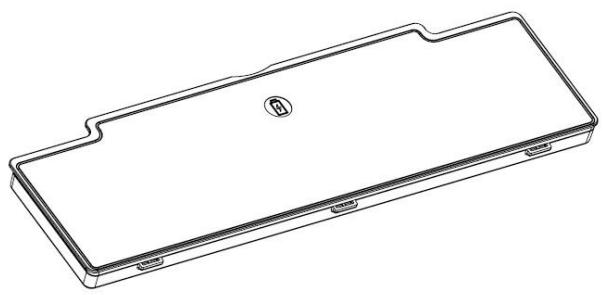
Battery specification: 2860 mAh, 11.1V
A.2.1.2 Installing the External Battery
- Align and insert the battery on the MIT-W102.
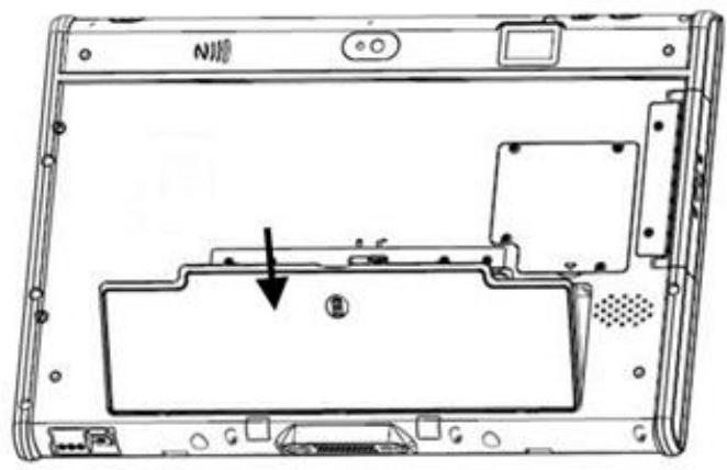
- Lock to secure the battery once it is properly to be inserted.
A.2.1.2 Removing the External Battery
Repeat the above steps in reverse order to remove the battery.
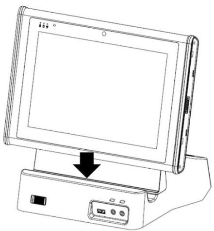
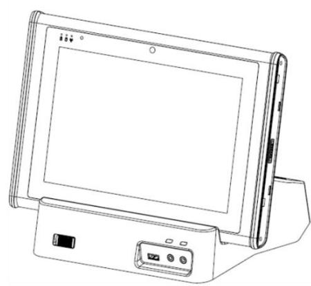
A.2.2 Office Docking Station
You can use the office docking stand to dock the MIT-M101 when you are at your home or on your office desk. When docked, you can charge both the internal and external batteries or transfer data from your MIT-M101 to another PC.
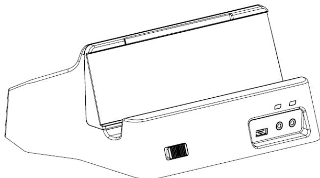
Attach the MIT-M101 to the docking stand as shown.
To charge the external battery, attach the battery to the docking stand as shown below.
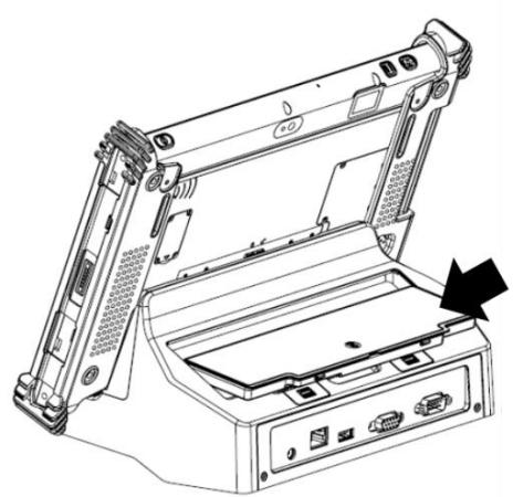
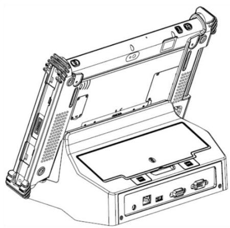
The external battery can also be charged when installed on the MIT-M101.
A.2.2.1 Docking Connectors
See below for the rear view of the docking and a description of all ports and connectors.
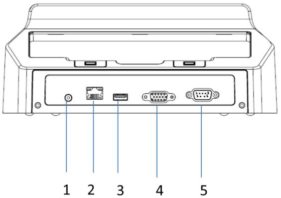
| No. | Component | Function |
| 1 | Power jack | Connect an RJ-45 cable to access LAN connection. |
| 2 | LAN port | Connect a serial cable to connect to another PC. |
| 3 | USB port | Connect USB connectors to transfer data. |
| 4 | VGA port | Connect the AC adapter to charge the battery. |
| 5 | COM port | Connect two devices (Input / Output). |
See below for the front view of the docking and a description of all ports and connectors.
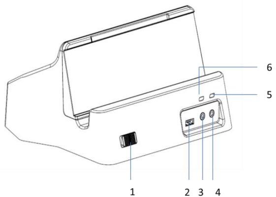
| No. | Function |
| 1 | Lock mechanism (quick load/unload) |
| 2 | USB port |
| 3 | Microphone jack |
| 4 | Headphone jack (Earphone Jack) |
| 5 | Dock detection LED |
| 6 | Battery bay status LED |
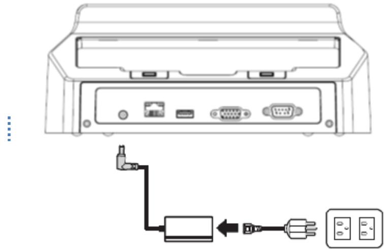
A.2.2.2 Connecting Power to the Docking
Connect the AC power adapter to the docking and the mains as shown below.
A.2.2.3 Docking Specifications
Feature Description
| Feature | Description |
| Product Name | MIT-W102 Docking Station |
| Model Number | MIT-W102-ACCDS |
| External I/O Interfaces | One LAN port One COM port One VGA port Two USB 2.0 host connectors One DC-in |
| Power | AC Adapter: AC 100V-250V 50/60Hz,1.5A(max) Output : 19Vdc/3.15A(max)/60W |
| Physical Size | 224.7 (H) x 200 (W) x 56.4 (D) mm |
A.2.3 VESA Docking Station
You can use the VESA docking station to dock the MIT-W102 to the place where you need via standard 75 × 75 mm VESA hole on rear side. When docked, you can transfer data from your MIT-W102 to another PC by COM port or USB port.
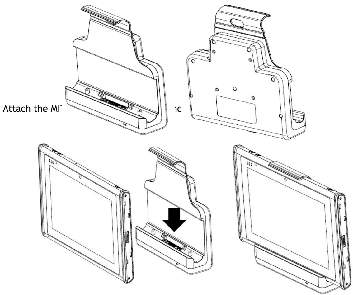
A.2.3.1 Docking Connectors
See below for the rear view of the docking and a description of all ports and connectors.
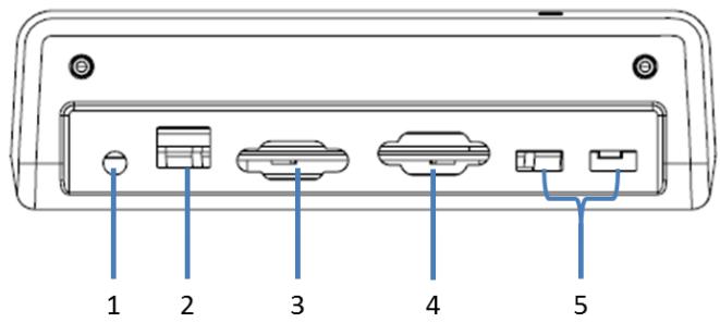
| No. | Component | Function |
| 1 | Power jack | Connect the AC adapter to provide power. |
| 2 | LAN port | Connect an RJ-45 cable to access LAN connection. |
| 3 | VGA port | Connect to display for 2nddisplay output |
| 4 | COM port | Connect a serial cable to connect to another PC. |
| 5 | USB port | USB 2.0 port x 2 , Connect USB connectors to transfer data. |
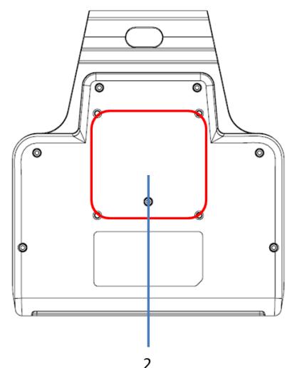
See below for the front view of the docking and a description of all ports and connectors.
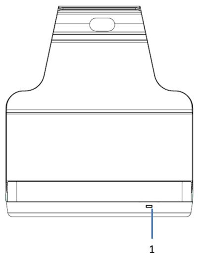
| No. | Function |
| 1 | LED indication / Device connected |
| 2 | Standard 75x75 VESA hole |
A.2.3.2 Connecting Power to the Docking
Connect the AC power adapter to the docking and the mains as shown below.
A.2.3.3 Docking Specifications
Feature Description
| Feature | Description |
| Product Name | MIT-W102 VESA Docking |
| Model Number | MIT-W102-ACCVD |
| External I/O Interfaces | One LAN port One COM port One VGA port Two USB 2.0 host connectors One DC-in |
| Power | AC Adapter: AC 100V-250V 50/60Hz,1.5A(max) Output : 19Vdc/3.15A(max)/60W |
| Physical Size | 224.7 (H) x 200 (W) x 56.4 (D) mm |
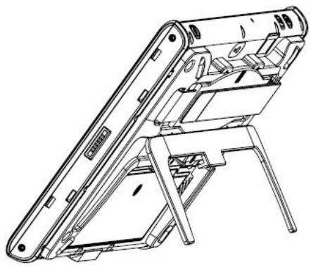
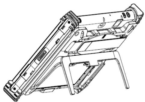
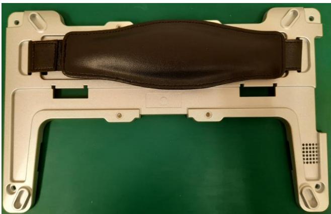
A.2.4 Adjustable Stand (with the hand strap)
You can use the adjustable stand to provide desk support when you are at home or in your office.
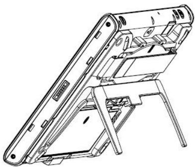
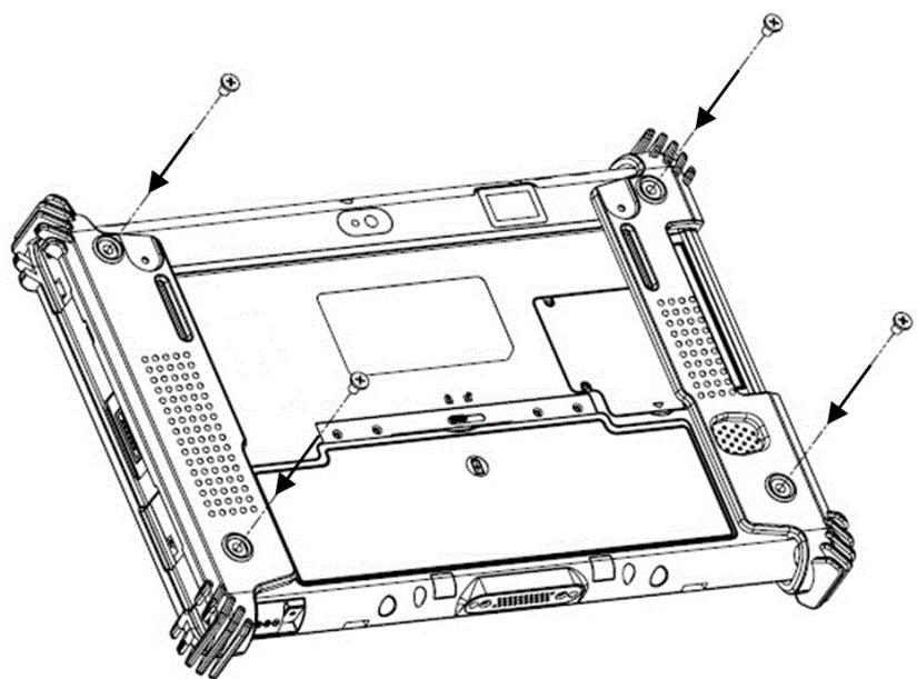
A.2.4.1 Attaching the Adjustable Stand
- Fasten four screws to attach the 3-in-1 multi-functional back cover to your MIT-M101 with or without rubber bumpers attached to the tablet.
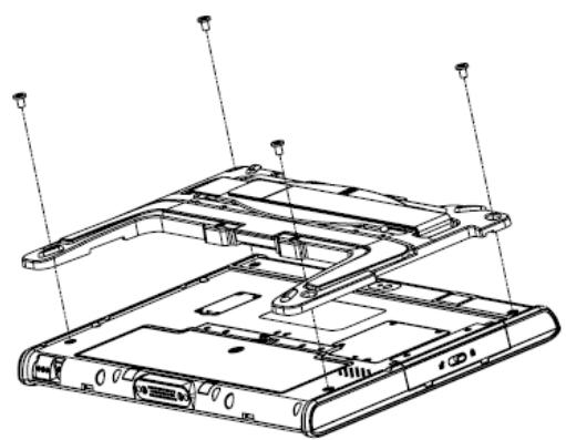
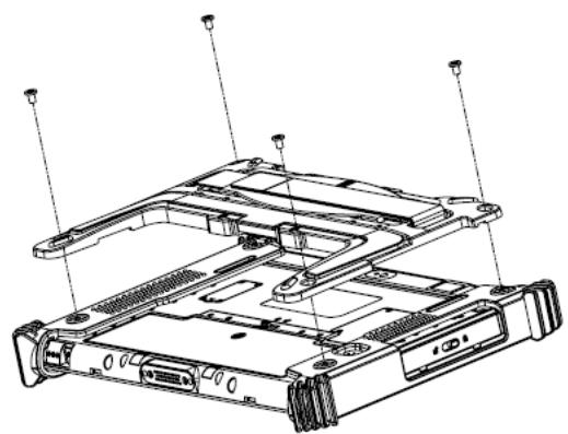
- Pull to adjust the stand to desirable angle.
A.2.4.2 How to install the hand strap on the stand
- Pass the end of the hand strap through the outer hole on each side of the stand
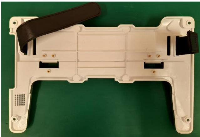
- Pass the end of the hand strap through the inner hole on each side of the stand and stick the hand strap together
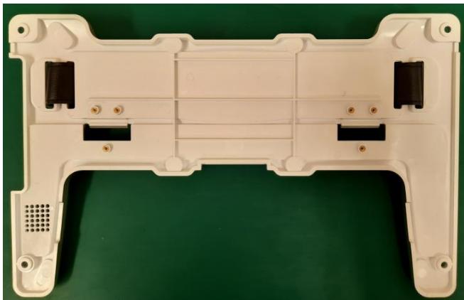
- Check if the length of the hard strap is OK.
A.2.5 Rubber Bumper
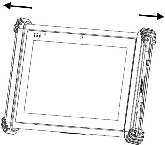
A.2.5.1 Installing the Rubber Bumpers
To protect the housing case of MIT-W102, install the rubber bumpers.
- Install the rubber bumpers on the left and right side of the MIT-W102.
- Make sure the rubber bumpers are aligned and locked on the indents.
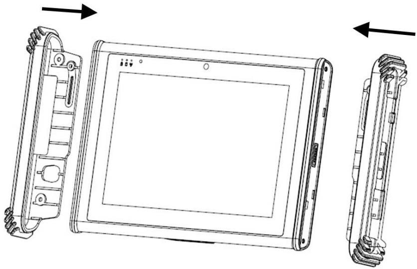
- Screw the rubber bumpers on left and right properly into the MIT-W102.
The Rubber bumper could provide well drop protection when device fall from high place. Please assure the rubber was put on the right position and the screws was fastened when install the bumper on device.
A.2.5.2 Removing the Rubber Bumpers
- Unscrew the rubber bumpers from the rear of the tablet PC.
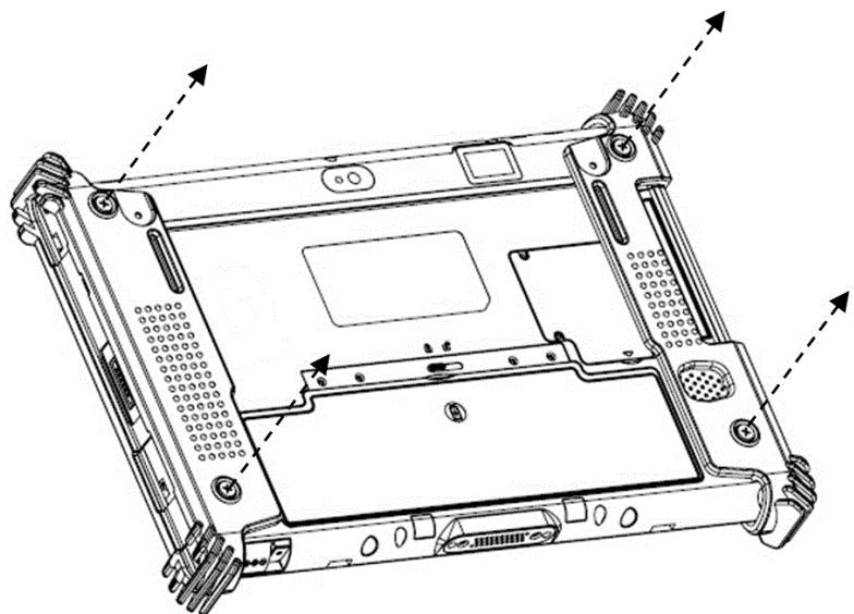
- Remove the rubber bumpers on the left and right.
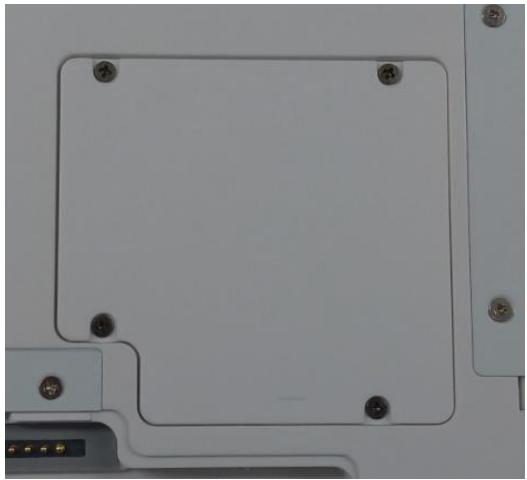
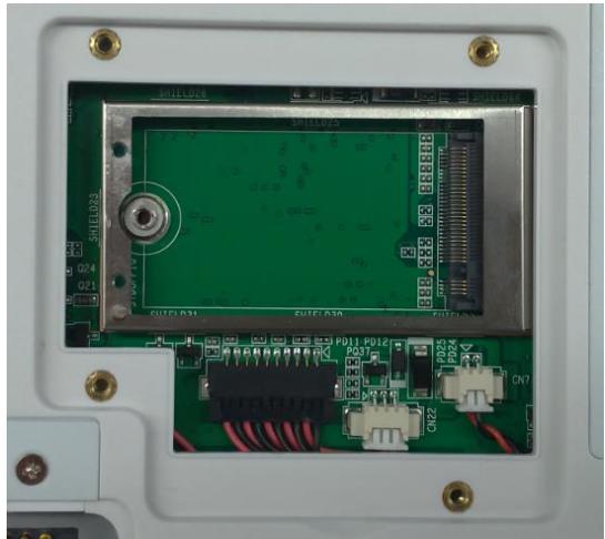
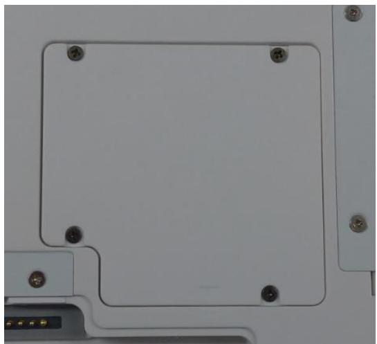
A.3 Installing SSD
Inserting SSD
You can insert an SDD to store data, which needs to be later transferred to another machine, or to simply expand the storage capacity of the MIT-W102.
- Open the SSD card compartment cover.
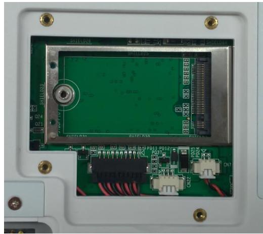
- Insert the SDD, facing upwards, until it clicks into place. Screw and fix SSD
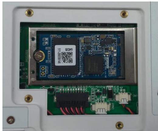
- Screw and fix the shielding case.
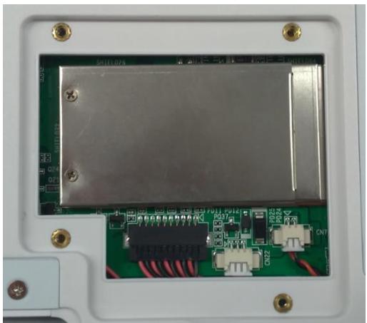
- Close the SDD compartment cover.
Removing SSD
- Open the SSD compartment cover.
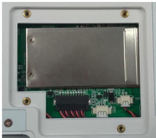
- Unscrew and remove the shielding case
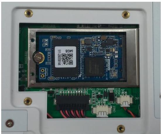
- Unscrew and remove SSD from the slot.
- Close and screw the SSD card compartment cover.
- MIT-W102XXXXXXXXXXXXXX
- User Manual
- Copyright
- Acknowledgements
- Intended use
- Intended user group
- Declaration of Conformity
- CE Conformity Statement
- FCC Compliance Statement
- RF Exposure Information (SAR)
- IC Compliance Statement
- Technical Support and Assistance
- Details of preparatory treatment or disposal
- Safety Instructions
- Battery Pack Caution
- Battery Charge Notice
- Storage and Safety Notice
- Disposing of Batteries or Battery Pack.
- Chapter 1 Ready to Go. 16
- Chapter 2 Making Connections 24
- Chapter 3 Turning On 28
- Chapter 4 Wireless Connections 35
- Chapter 5 Advance Setting 43
- Chapter 6 Dashboard and Hotkey setting 49
- Appendix Specifications 58
- Chapter 1 Ready to Go
- Symbols Used in this Manual
- Product Features
- Package Contents
- System Configuration
- Exploring the MIT-W102
- Front View
- Rear View
- Right View
- Left View
- Top View
- Bottom View
- Chapter 2 Making Connections
- Connecting the Power
- Connecting to a Monitor
- Connecting USB Devices
- Connecting Headphones
- Connecting a Microphone
- Chapter 3 Turning On
- Controlling the MIT-W102
- Using the Touch Screen
- Using the Tap Function
- Using the Control Panel Buttons
- Using the On-Screen Keyboard
- Tap the icon on the taskbar to open the keyboard
- Use your finger or stylus pen to tap and enter letters, numbers and symbols as you would with a regular keyboard. To type capital letters tap the lock icon on the on-screen keyboard.
- a. To use handwriting, tap upper left button of On-Screen Keyboard.
- Adjusting Screen Brightness
- Adjusting the Volume
- Tap the Volume icon on taskbar
- Move the slide to adjust volume to tap the icon to mute
- Chapter 4 Wireless Connections
- Wi-Fi Connection
- Bluetooth Connections
- Setting Up Bluetooth
- When enabled, Bluetooth icon will be shown on the taskbar
- Add more Bluetooth device by clicking on the icon “+”
- Select "Bluetooth"
- Select the Bluetooth device to connect from the available device menu
- Chapter 5 Advance Setting
- Checking Battery Status
- Maintenance
- Maintaining the Battery
- Maintaining the LCD Display
- Cleaning the MIT-W102
- Trouble Shooting
- Chapter 6 Dashboard and Hotkey setting
- Dashboard
- NFC
- NFC application
- NFC Setting
- Select COM port number 2
- Open Port
- Select Card Type
- Polling Start
- NFC Usage
- camera
- Brightness
- Hotkey Setting
- Appendix Specifications
- A.1 Specifications
- A.2 Optional Accessories
- A.2.1 External Battery
- A.2.1.2 Installing the External Battery
- A.2.1.2 Removing the External Battery
- A.2.2 Office Docking Station
- A.2.2.1 Docking Connectors
- A.2.2.2 Connecting Power to the Docking
- A.2.2.3 Docking Specifications
- A.2.3 VESA Docking Station
- A.2.3.1 Docking Connectors
- A.2.3.2 Connecting Power to the Docking
- A.2.3.3 Docking Specifications
- A.2.4 Adjustable Stand (with the hand strap)
- A.2.4.1 Attaching the Adjustable Stand
- A.2.4.2 How to install the hand strap on the stand
- A.2.5 Rubber Bumper
- A.2.5.1 Installing the Rubber Bumpers
- A.2.5.2 Removing the Rubber Bumpers
- A.3 Installing SSD
- Inserting SSD
- Removing SSD
Brand : Advantech
Model : MIT-W102
Category : Laptop