
TM-S2000II - Multifunction Printer EPSON - Free user manual and instructions
Find the device manual for free TM-S2000II EPSON in PDF.
| Product Type | Compact multifunction printer with bank teller functions |
| Brand | EPSON |
| Model | TM-S2000II |
| Dimensions (single bin model) | Height: 206 mm, Width: 142 mm, Depth: 263.8 mm (stored) / 374.8 mm (bin extended) |
| Dimensions (two bin model) | Height: 206 mm, Width: 167 mm, Depth: 298.8 mm (stored) / 409.8 mm (bins extended) |
| Weight (single bin model) | Approximately 3.7 kg |
| Weight (two bin model) | Approximately 4.1 kg |
| Power supply | Dedicated AC adapter PS-180: input 100-240 V AC, 50/60 Hz, 1.3 A; output 24 V DC, 2.1 A |
| Power consumption | During operation: approximately 51.3 W; during standby: approximately 5.9 W |
| Printing method | Line inkjet, black, 360 nozzles (2 lines) |
| Print resolution | 180 x 180 dpi |
| Main functions | Printing (check endorsement, receipts), magnetic ink character recognition (MICR), duplex scanning of sheets and ID cards, magnetic stripe card reader (MSR) depending on model |
| Processing speed | 130 DPM or 225 DPM depending on the model |
| Automatic sheet feeder (ASF) capacity | Up to 100 sheets (check paper up to 0.13 mm thickness) |
| Output bin capacity | Main bin: up to 100 sheets; secondary bin: up to 50 sheets (two bin model) |
| Supported paper sizes | Width: 60 to 120 mm, length: 100 to 235 mm, thickness: 0.075 to 0.2 mm |
| Interface | USB 2.0 (Type B and Type A depending on model) |
| MICR recognition | E13B and CMC7 fonts, recognition rate ≥ 99% (ANSI standard at 25 °C) |
| Scanning | CIS sensor, resolutions up to 300 dpi (sheets) or 600 dpi (ID cards), binary, grayscale, color and infrared modes |
| Maintenance and cleaning | Cleaning of the ink head, paper path (cleaning kit recommended) and scanner glass |
| Safety | Automatic stop in case of error, ink head cap, installation and power supply precautions |
| Spare parts and repairability | SJIC18(K) black ink cartridge, PS-180 AC adapter |
| General information | NV memory for logos and settings, high-speed and confirmation processing modes, remote maintenance functions |
Frequently Asked Questions - TM-S2000II EPSON
User questions about TM-S2000II EPSON
0 question about this device. Answer the ones you know or ask your own.
Ask a new question about this device
Download the instructions for your Multifunction Printer in PDF format for free! Find your manual TM-S2000II - EPSON and take your electronic device back in hand. On this page are published all the documents necessary for the use of your device. TM-S2000II by EPSON.
USER MANUAL TM-S2000II EPSON
natural_image
Technical line drawing of a mechanical component housing (no text or symbols)Safety Precautions
Describes precautions that ensure safe use of the product. Read this first.
Product Overview
Describes product features.
Setup
Describes product and peripheral device installation and setup procedures.
Advanced Product Use
Describes advanced product use.
Application Development Information
Provides information required for controlling this product and application development.
Handling the Product
Describes the basic operating procedures of the product.
Troubleshooting
Describes what to do when problems occur.
Product Specifications
Provides product specifications, interface specifications, and character code tables.
Notes
- All rights reserved. No part of this publication may be reproduced, stored in a retrieval system, or transmitted in any form or by any means, electronic, mechanical, photocopying, recording, or otherwise, without the prior written permission of Seiko Epson Corporation.
- The content of this manual is subject to change without notice. Contact ESPON for the latest information.
- While every precaution has been taken in the preparation of this manual, Seiko Epson Corporation assumes no responsibility for errors or omissions.
- Neither is any liability assumed for damages resulting from the use of the information contained herein.
- Neither Seiko Epson Corporation nor its affiliates shall be liable to the purchaser of this product or third parties for damages, losses, costs, or expenses incurred by purchaser or third parties as a result of: accident, misuse, or abuse of this product or unauthorized modifications, repairs, or alterations to this product, or (excluding the U.S.) failure to strictly comply with Seiko Epson Corporation's operating and maintenance instructions.
- Seiko Epson Corporation shall not be liable for any damages or problems arising from the use of any options or any consumable products other than those designated as Genuine Epson Products or Epson Approved Products by Seiko Epson Corporation.
Copyrights
EPSON is a registered trademark of Seiko Epson Corporation.
Exceed Your Vision is a registered trademark or trademark of Seiko Epson Corporation.
Microsoft ^® and Windows ^® are registered trademarks of Microsoft Corporation in the United States, Japan, and/or other countries.
All other trademarks are the property of their respective owners and used for identification purpose only.
©Seiko Epson Corporation 2018. All rights reserved.
Table of Contents
■ Safety Precautions....7
Meanings of Symbols 7
Cautions on Installation....7
Cautions on Power Supply....7
Cautions on Handling....8
Cautions on Ink Cartridges 9
■ Restriction of Use 10
■ About This Manual.... 11
Purpose of This Manual....11
Manual Organization....11
Manual Illustrations....11
Product Overview 13
■ Features .... 13
■ Product Configuration .... 14
Model....14
Accessories 14
■ Part Names and Functions .... 15
Front....15
Operation Panel....17
Rear ....18
■ Checking the Product Status 19
Replacement Timing of Consumables....19
Statuses and Errors 20
■ Cut Sheet Processing Modes.... 24
High-speed Mode 24
Confirmation Mode....27
Speed of Each Processing Mode....31
■ NV Memory 33
NV Graphics Memory....33
NV User Memory ....33
Memory Switch....33
User-defined Page 33
Maintenance Counters....34
Setup 35
■ Setup Flow.... 35
■ Product Installation 36
Removing the Packing Materials....36
Installation 36
■ Connecting to a Host Computer.... 37
■ Connecting a Power Supply 38
■ Installing the Ink Cartridges.... 39
■ Adjusting LCD Backlight Brightness....41
■ Test Printing 42
Advanced Product Use.... 45
■ Software Settings....45
Function 45
■ Setting/Confirmation Mode 48
Self-test Mode......49
NV Graphics Information Print Mode 50
Application Development Information 51
■ Operating Environment 51
130 DPM Model....51
225 DPM Model....51
■ Driver 52
For Windows Environment....52
For Linux Environment 53
■ Utilities .... 54
TM-S2000II Utility 54
Epson Deployment Tool 54
■ Downloading Software 55
Handling the Product 57
■ Turning On/Off....57
Turning the Power On....57
Turning the Power Off....57
■ Opening a Cover....58
Opening the Ink Cartridge Cover....58
Opening the MICR Cover or Scanner Cover 58
■ Replacing the Ink Cartridges....59
■ Cut Sheet Processing 60
Process Flow 60
Loading Cut Sheets....61
Removing Cut Sheets 62
■ ID Card Processing 63
■ Magnetic Stripe Card Processing 64
■ Cleaning the Product....65
Cleaning the Exterior 65
Ink Head Cleaning....65
Cleaning the Paper Feeding Path....66
Cleaning the Scanner 68
■ Preparing for Transport....69
Troubleshooting....71
■ The Product Does Not Turn On.... 72
■ Lit or Flashing ! (ERROR) LED....72
■ Error Message Displayed on the LCD 73
Recoverable Error....73
Unrecoverable Error ....75
■ Cut Sheet Jam 76
■ ID Card Does Not Come Out....77
■ Problems with Print Quality....78
■ Problems with Reading Quality....78
Cannot Read Magnetic Ink Characters Correctly....78
Poor Cut Sheet or ID Card Reading Quality ....78
Product Specifications....79
■ General Specifications .... 79
Electrical Specifications ....80
Ink Cartridge 80
■ USB Interface Specifications .... 81
USB (Type-B) 81
USB (Type-A) 81
■ Printing Specifications 82
■ Character Specifications....83
■ Scanner Specifications....84
■ MSR (Magnetic Stripe Reader) Specifications 85
■ Paper Specifications 86
■ Printable Area 87
■ Scanner Scan Area 88
Cut Sheet....88
ID Card 89
■ MICR Reading Area 90
Electronic Endorsement Area 90
■ Environmental Specifications....91
■ Reliability 91
■ Overall Dimensions....92
One-pocket Model 92
Two-pocket Model 93
■ Character Code Tables....94
Safety Precautions
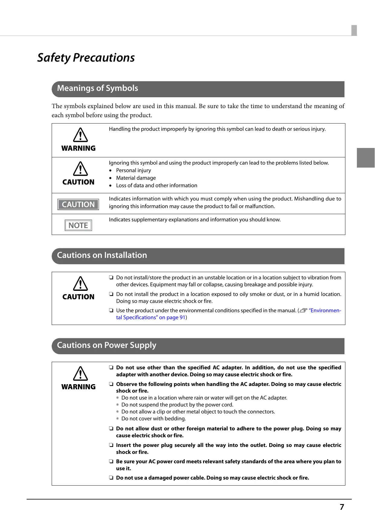
Meanings of Symbols
The symbols explained below are used in this manual. Be sure to take the time to understand the meaning of each symbol before using the product.

WARNING
Handling the product improperly by ignoring this symbol can lead to death or serious injury.

CAUTION
Ignoring this symbol and using the product improperly can lead to the problems listed below.
- Personal injury
- Material damage
- Loss of data and other information
CAUTION
Indicates information with which you must comply when using the product. Mishandling due to ignoring this information may cause the product to fail or malfunction.
NOTE
Indicates supplementary explanations and information you should know.
Cautions on Installation

CAUTION
☐ Do not install/store the product in an unstable location or in a location subject to vibration from other devices. Equipment may fall or collapse, causing breakage and possible injury.
☐ Do not install the product in a location exposed to oily smoke or dust, or in a humid location. Doing so may cause electric shock or fire.
☐ Use the product under the environmental conditions specified in the manual. (☐ "Environmental Specifications" on page 91)
Cautions on Power Supply

WARNING
☐ Do not use other than the specified AC adapter. In addition, do not use the specified adapter with another device. Doing so may cause electric shock or fire.
☐ Observe the following points when handling the AC adapter. Doing so may cause electric shock or fire.
* Do not use in a location where rain or water will get on the AC adapter.
* Do not suspend the product by the power cord.
* Do not allow a clip or other metal object to touch the connectors.
* Do not cover with bedding.
☐ Do not allow dust or other foreign material to adhere to the power plug. Doing so may cause electric shock or fire.
☐ Insert the power plug securely all the way into the outlet. Doing so may cause electric shock or fire.
☐ Be sure your AC power cord meets relevant safety standards of the area where you plan to use it.
☐ Do not use a damaged power cable. Doing so may cause electric shock or fire.
 WARNING WARNING | □ Contact qualified service personnel for advice if the power cable is damaged. Furthermore, observe the following points so as not to damage the power cable.* Do not modify the power cable.* Do not place heavy objects on the power cable.* Do not forcibly bend, twist, or pull the power cable.* Do not lay the power cable near a heating appliance.□ Do not insert or remove the power plug with a wet hand. Doing so may cause electric shock.□ Do not connect many power cables to one outlet. Doing so may cause fire.□ Regularly disconnect the power plug from the outlet and clean the base of the prongs and between the prongs. Leaving the power plug connected to the outlet for a long period of time may cause dust to accumulate on the base of the power plug prongs, resulting in a short and fire.□ Hold the plug and do not pull the cable when disconnecting the power plug from the outlet. Pulling the cable may damage the cable or deform the plug, causing electric shock or fire. |
| CAUTION | □ To ensure safety, unplug the product before leaving it unused for an extended period. |
Cautions on Handling
  | Do not use the product in a location with volatile substances such as alcohol or paint thinner present, or near fire. Doing so may cause electric shock or fire.Shut down the product immediately if it produces smoke, a strange odor, or unusual noise. Doing so may cause electric shock or fire. If an abnormality occurs, immediately turn off the power and remove the plug from the outlet, and then contact qualified service personnel for advice.Shut down the product immediately if a foreign object or water or other liquid gets inside the product. Continued use may cause electric shock or fire. Immediately turn off the power and remove the plug from the outlet, and then contact qualified service personnel for advice.Never disassemble or repair the product by yourself as doing so is dangerous.Do not use the product in a location where inflammable gas, explosive gas, etc. is present in the atmosphere. Furthermore, do not use aerosol sprayers containing flammable gas inside or around the product. Doing so may cause fire.Do not connect cables in ways other than those mentioned in this manual. Doing so may cause fire. It may also damage the other connected devices.(“Connecting a Power Supply” on page 38, “Connecting to a Host Computer”)Do not touch the areas inside the product other than those mentioned in this manual. Doing so may cause electric shock or burns.Do not insert metal or flammable materials, or allow them to fall into the product. Doing so may cause electric shock or fire. |
  | Do not allow anyone to stand or place heavy objects on top of the product. Equipment may fall or collapse, causing breakage and possible injury.Install the cables and optional products in the proper direction according to the proper procedures. Failure to do so creates the risk of fire or electric shock. Follow the instructions in this manual to install them properly.(“Connecting a Power Supply” on page 38, “Connecting to a Host Computer”)Before moving the product, shut down and unplug the product, and make sure that all the cables are disconnected. Failure to do so may damage a cable, causing electric shock or fire.Do not store or transport the product while it is tilted, standing, or upside down. Doing so may cause the ink to leak. |
Cautions on Ink Cartridges

☐ Do not touch the IC chip on an ink cartridge. Doing so may result in normal operation and printing becoming no longer possible.
☐ The product uses ink cartridges equipped with IC chips to manage the amount of ink used and other information so ink cartridges are usable even if they are removed and reinstalled. However, if an ink cartridge with not much ink remaining is removed and reinstalled, it may not be usable. Some ink is consumed each time cartridges are installed because the product automatically checks their reliability.
☐ Since ink cartridges are designed to stop the operation before ink runs out completely to maintain the quality of the ink head, some ink remains in the used ink cartridges.
☐ In order to keep the ink head in good condition, ink is also consumed during such non-printing maintenance operations such as ink cartridge replacement.
☐ Do not turn off the power or open the cover during ink charging (while the ① (Power) LED is flashing). Opening the cover may cause the ink to be recharged, resulting in more ink being consumed. Also, it may result in normal printing becoming no longer possible.
☐ Do not disassemble an ink cartridge. Doing so may cause ink to get into eyes or onto skin.
☐ Do not disassemble or modify an ink cartridge. Doing so may cause printing malfunction.
☐ Use of old ink cartridges may result in reduced print quality. Use ink cartridges up within six months after opening the packages. The usage period for ink cartridges is printed on the packaging of the individual ink cartridges.

☐ If ink contacts your skin, eyes, or mouth, take the following actions.
* When ink gets onto your skin, immediately wash the area with soap and water.
* When ink gets into your eyes, immediately flush them with water. Leaving the ink as is may result in bloodshot eyes or mild inflammation. If something is wrong, immediately consult with a doctor.
* When ink gets into your mouth, immediately spit it out and consult with a doctor.
☐ There may be some ink around the ink supply port on a removed ink cartridge. Take care so that it does not stain the desk or other surface.
☐ Do not remove the ink cartridge except to replace it.
☐ Do not open an ink cartridge package until you are ready to install the ink cartridge in the product.
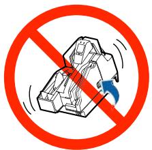
☐ Do not shake an ink cartridge too hard. The ink cartridge may leak if you shake it around too much or push the sides strongly.
☐ Do not allow foreign objects to fall into the cartridge installation section. Doing so may result in normal printing becoming no longer possible. Remove any object that falls into the installation section, taking care not to damage the section.
☐ When ink is charged the first time (right after purchase), ink is consumed for filling the ink head nozzles (ink discharge holes) to get ready for printing. Because of this, the number of sheets that can be printed by the first ink cartridge used in a new product may be lower than that of the second and subsequent ink cartridges.
☐ Turning off the product by performing a ⏻ (POWER) button operation or by sending a command causes the ink head to be capped automatically to prevent the ink from drying. If you do not plan to use the product after installing an ink cartridge, be sure to use either of the methods above to turn off power. Do not pull out the power plug or turn off the breaker while the power is on.
☐ Printing on water-repellent paper such as art paper, which is slow-drying, may cause print stains. Also, if you print on glossy paper, fingerprints may get on the paper or ink may adhere to your fingers when you touch the print surface. Select and use paper that will not cause print stains.
☐ Store the ink cartridges in a place out of reach of children.
☐ Epson recommends storing ink cartridges in a cool and dark place.
☐ If you wish to use ink cartridges that have been stored in a cold place for a long period of time, leave them for at least 3 hours in a place that is at room temperature before use.
☐ Do not remove the ink cartridges from the product when storing the product.
Restriction of Use
When this product is used for applications requiring high reliability/safety such as transportation devices related to aviation, rail, marine, automotive etc.; disaster prevention devices; various safety devices etc.; or functional/precision devices etc., you should use this product only after giving consideration to including fail-safes and redundancies into your design to maintain safety and total system reliability.
This product in not intended for use in aerospace equipment, main communication equipment, nuclear power control equipment, medical equipment, or other applications that require a very high level of reliability and/or safety. Be sure to check with the customer concerning these applications and judge applicability accordingly.
About This Manual
Purpose of This Manual
This manual is intended to provide development engineers with information about product functions, operations, maintenance, and troubleshooting, and the information needed for application development and design.
Manual Organization
This manual is organized as shown below.
Chapter 1 Product Overview
Chapter 2 Setup
Chapter 3 Advanced Product Use
Chapter 4 Application Development Information
Chapter 5 Handling the Product
Chapter 6 Troubleshooting
Chapter 7 Product Specifications
Manual Illustrations
Unless specifically indicated otherwise, all illustrations in this manual show a model equipped with two pockets and MSR.
Product Overview
This chapter describes the features and functions of the product.
Features
This product is a compact multifunction device that incorporates various functions required by banking counter services.
☐ Cut sheet (check endorsement, single receipt, cashier's check) printing
- 360-nozzle inkjet printing enables 180 dpi multi-line, high-resolution output [dpi: dot per inch]
☐ Check magnetic ink character recognition
☐ Cut sheets, personal ID (driver's license) two-side data acquisition
• Binary (cut sheets only), gray scale, color, IR (infrared) image acquisition
☐ Auto sheet feeder that automatically feeds cut sheets one sheet at a time
• Cut sheet overlap feed detector
- Check mis-insertion detector
• Image quality assessment (IQA) (supported by driver)
• Optical character recognition (OCR) (supported by driver) ^*1
☐ Two-pocket cut sheet separator ^*2
☐ Magnetic stripe card reader (MSR) ^*2
☐ LCD for quick and easy determination of product status
□ Equipped with USB-HUB ^*2
☐ Counter that comes in handy for remote maintenance
Built-in buzzer
*1: Supported fonts are OCR-A and OCR-B only
*2: Depends on model
Product Configuration
Functions and accessories for this product depend on the model.
Model
| Cut sheet print processing speed | Number of cut sheet pockets | MSR | USB-HUB |
| 130 DPM | One-pocket | Unequipped | Unequipped |
| Equipped | Equipped | ||
| Two-pocket | Unequipped | Unequipped | |
| Equipped | Equipped | ||
| 225 DPM | One-pocket | Unequipped | Unequipped |
| Equipped | Equipped | ||
| Two-pocket | Unequipped | Unequipped | |
| Equipped | Equipped |
[DPM: Number of cut sheets processed per minute (Documents Per Minute)]
Accessories
☐ Special ink cartridge SJIC18(K) x 2
☐ Dedicated AC adapter PS-180
☐ USB cable (length: 170 cm, color: black)
□ AC cable*
☐ Instruction manuals
*: Not included with some models
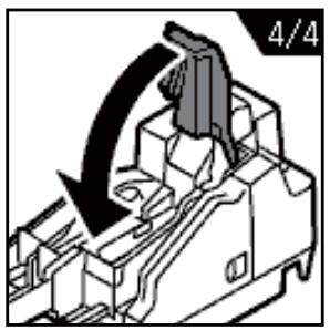
Part Names and Functions
Front
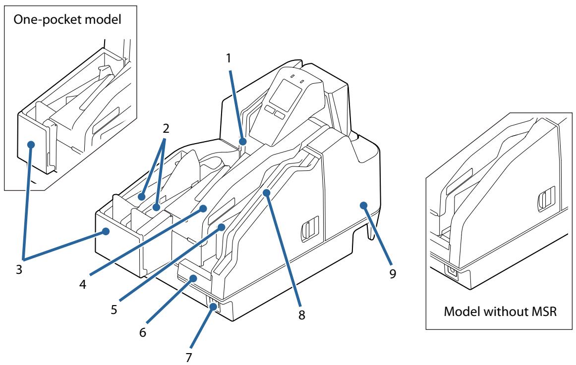
| 1 | ID card slot |
| To read an ID card, insert it. (☐ "ID Card Processing" on page 63) | |
| 2 | Main pocket/Sub-pocket |
| Pockets hold cut sheets ejected after processing. | |
| 3 | Pocket guides |
| Pull out the pocket guide to match the length of the cut sheets being used. | |
| 4 | Ink cartridge cover |
| Open this cover to install/replace the ink cartridge. (☐ "Installing the Ink Cartridges" on page 39, "Replacing the Ink Cartridges") | |
| 5 | ASF (Auto-Sheet-Feeder) |
| Install the Auto-Sheet-Feeder to feed checks and other cut sheets. Up to 100 sheets can be fed. (☐ "Cut Sheet Processing" on page 60) | |
| 6 | ASF guide |
| Pull out the pocket guide to match the length of the cut sheets being used. | |
| 7 |  |
| Turn the product on/off. (“Turning On/Off” on page 57) | |
| 8 | MSR (Magnetic Stripe Reader) |
| To read a magnetic strip card, insert the card and slide it. (“Magnetic Stripe Card Processing” on page 64) | |
| 9 | MICR cover |
Open this cover if cut sheets become jammed. (☐ "Opening the MICR Cover or Scanner Cover" on page 58, "Cut Sheet Jam")
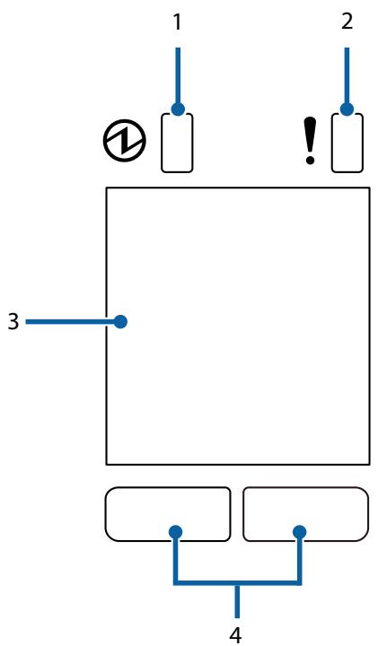
Operation Panel
flowchart
graph TD
    A["1"] --> B["2"]
    B --> C["3"]
    C --> D["4"]
    style A fill:#f9f,stroke:#333
    style B fill:#bbf,stroke:#333
    style C fill:#fff,stroke:#333
    style D fill:#dfd,stroke:#333
| 1 | 1 (POWER)LED |
Lights when the product is turned on.
Flashes during printing and while ink is charging.
| 2 | ! (ERROR) LED |
Lights when an error occurs. (☐ "Checking the Product Status" on page 19)
| 3 | LCD |
Shows the status of consumables and the product. (☐ "Checking the Product Status" on page 19)
LCD backlight brightness is adjustable. (☐ "Adjusting LCD Backlight Brightness" on page 41)
| 4 | Button 1 (Left) / Button 2 (Right) |
Each button is assigned the corresponding function that appears at the bottom of the LCD. The function on the lower left of the LCD is executed when Button 1 (left button) is pressed, while the function on the lower right is executed when Button 2 (right button) is pressed.

Button 1
Button 2
Rear
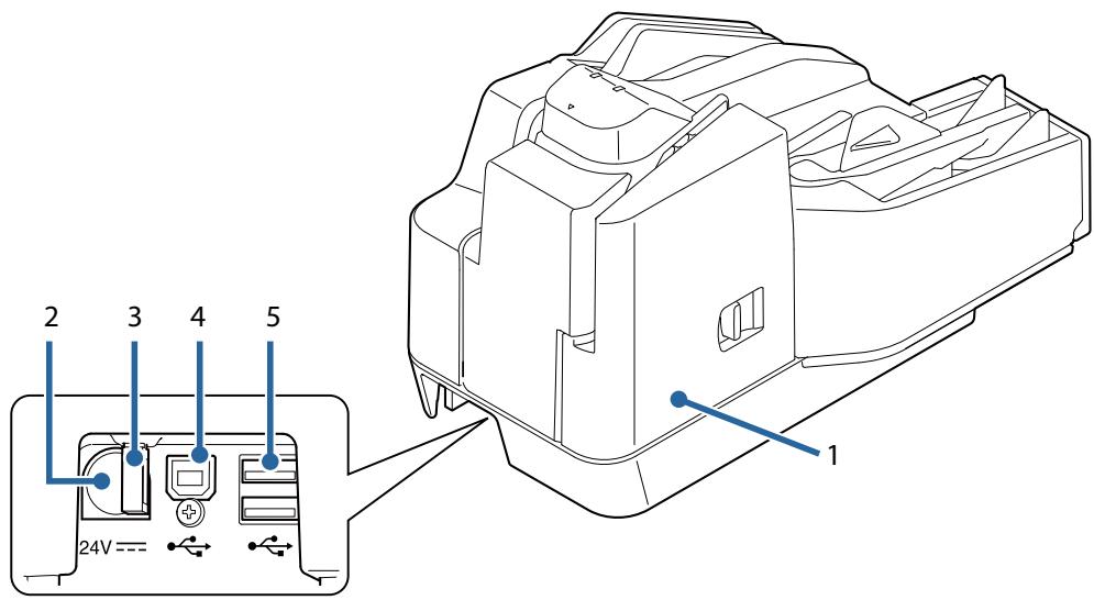
| 1 | Scanner cover |
| Open this cover if cut sheets or an ID card becomes jammed. (“Opening the MICR Cover or Scanner Cover” on page 58, “Cut Sheet Jam”, “ID Card Does Not Come Out”) | |
| 2 | DC-IN connector |
| Connect a DC cable. | |
| 3 | Wire saddle |
| Pass the USB cable through this saddle to prevent disconnection of the cable. | |
| 4 | USB connector (Type B) |
| Connect a USB cable (Type B). | |
| 5 | USB connector (Type A) |
Connect a USB cable (Type A).
Checking the Product Status
The status of the product can be checked from a combination of the LEDs lighting/flashing and the LCD display.

The error type cannot be distinguished by the LED pattern. Develop an application that reads the status from the application and identifies the error, and lets the user know the required recovery procedure.
Replacement Timing of Consumables
The ink cartridge status can be checked on the LCD home screen.
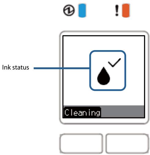
| LCD display | Status |
 | There is sufficient ink remaining. |
 | There is not much ink remaining so nearly time to replace the ink cartridge. Prepare a new ink cartridge. |
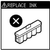
 | Ink cartridge is expended. Loading or replacement of the ink cartridge is required. Printing on cut sheet is not possible until a new ink cartridge is installed. (Ink cartridge replacement guidance appears on the LCD. “Replacing the Ink Cartridges” on page 59) |
 | An ink cartridge is not installed. An ink cartridge must be loaded to print on cut sheets. |
 | There is not enough ink for periodic ink head cleaning. The ink cartridge needs to be replaced to perform cleaning. |
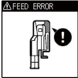
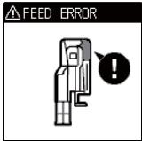
Statuses and Errors
The status of the product can be checked from a combination of the LEDs lighting/flashing and the LCD display.
Product operation stops when an error occurs. For details on resolving errors, refer to “Error Message Displayed on the LCD” on page 73.
□:Off
□ / □ :On
/ :Flashing
| LED | LCD display | Product status | |
| [weow]POWER | [weu]ERROR | ||
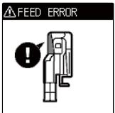
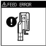
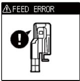
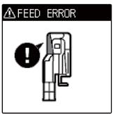
 | FEED ERROR | Cut sheets are jammed in the MICR reader. (“Cut Sheet Jam” on page 76) | |
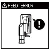
 |  | Cut sheets are jammed in the scanner(“Cut Sheet Jam” on page 76) | |
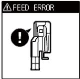
 | 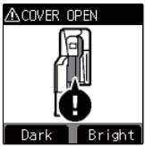 | Ink cover is open | |
| [20X48]POWER | ERROR | ||
| [T230] | ☐ | 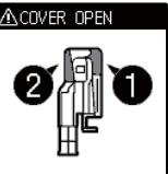 | Open MICR cover and/or scanner cover |
| [26V7T] | ☐ | 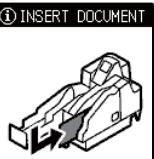 | Standing by for insertion of cut sheets |
| [29+1] | ☐ | 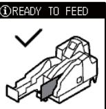 | Cut sheet detection |
| [17TCC] | ☐ | 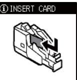 | Card insertion standby |
| [T5XT] | ☐ | 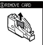 | Card removal standby |
| [46+Y] | ☐ | 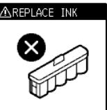 | Cartridge loading or replacement required(“Installing the Ink Cartridges” on page 39) |
| [244] | ☐ |  | Ink head cleaning standby(“Ink Head Cleaning” on page 65) |
| ☐ |  | Ink head cleaning | |
| [WBAS]POWER | ERROR | ||
| Dwina41 | [100] |  | Ink head high temperatureMotor driver high temperature |
| Dwada5 | [179] |  | In power-on sequenceIn power-off sequence |
| Dwada5 | [181] | 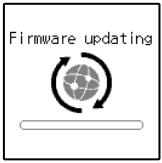 | Firmware rewriting (data receive in progress) |
| Dwada5 | [182] | 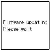 | Firmware rewriting (data writing, restoration in progress) |
| Dwada6 | [183] |  | The pump unit is near the end of it's service life |
| Dwada5 | [184] |  | Unrecoverable error(“Unrecoverable Error” on page 75) |
| POWER | !ERROR | ||
| [5548] | □ | ⚠ INFORMATIONNot enough ink for maintenance. There is a risk of affecting inkjet print quality. TheNow Later⚠ INFORMATIONcleaning process requires a new ink cartridge to be completed. Change ink cartridge now?Now Later⚠ INFORMATIONWithout cleaning inkjet print quality may decrease. Change ink cartridge now?Now Later | Insufficient ink for periodic ink head cleaning |
Cut Sheet Processing Modes
There are two modes for processing cut sheets. Select the method most suitable for your environment.
- High-speed mode (☐ “High-speed Mode” on page 24)
- Confirmation mode (☐ “Confirmation Mode” on page 27)
For details on processing modes, refer to the TM-S2000MJ API Reference Guide.
High-speed Mode
Use this mode to specify processing conditions from the firmware or driver.
Table of Judgment Subjects and Criteria
| Judgment made by: | Criteria |
| Firmware | Overlapping feeding detection resultIncorrect insertion detection result (Check paper)Magnetic waveform detection resultExternal noise detection resultPrinting result of exceeded media length |
| Driver | MICR “?” detection resultIQA judgment resultBarcode recognition result |
Document Processing Sequence
The processing sequence depends on the number of pockets and whether or not back feeding is being performed.
When back feeding is not necessary with 1-pocket models/2-pocket models
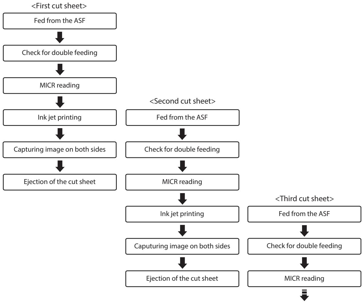
flowchart
graph TD
    A["<First cut sheet>"] --> B["Fed from the ASF"]
    B --> C["Check for double feeding"]
    C --> D["MICR reading"]
    D --> E["Ink jet printing"]
    E --> F["Capturing image on both sides"]
    F --> G["Ejection of the cut sheet"]

    H["<Second cut sheet>"] --> I["Fed from the ASF"]
    I --> J["Check for double feeding"]
    J --> K["MICR reading"]
    K --> L["Ink jet printing"]
    L --> M["Capturing image on both sides"]
    M --> N["Ejection of the cut sheet"]

    O["<Third cut sheet>"] --> P["Fed from the ASF"]
    P --> Q["Check for double feeding"]
    Q --> R["MICR reading"]
    R --> S["End"]
When back feeding is required with 2-pocket models
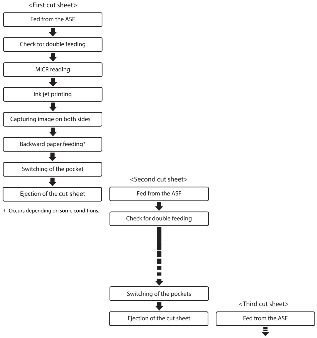
flowchart
graph TD
    A["First cut sheet>"] --> B["Fed from the ASF"]
    B --> C["Check for double feeding"]
    C --> D["MICR reading"]
    D --> E["Ink jet printing"]
    E --> F["Capturing image on both sides"]
    F --> G["Backward paper feeding*"]
    G --> H["Switching of the pocket"]
    H --> I["Ejection of the cut sheet"]
    I --> J["<Second cut sheet> Fed from the ASF"]
    J --> K["Check for double feeding"]
    K --> L["Switching of the pockets"]
    L --> M["Ejection of the cut sheet"]
    M --> N["<Third cut sheet> Fed from the ASF"]
    N --> O["End"]
    style A fill:#f9f,stroke:#333
    style O fill:#f9f,stroke:#333
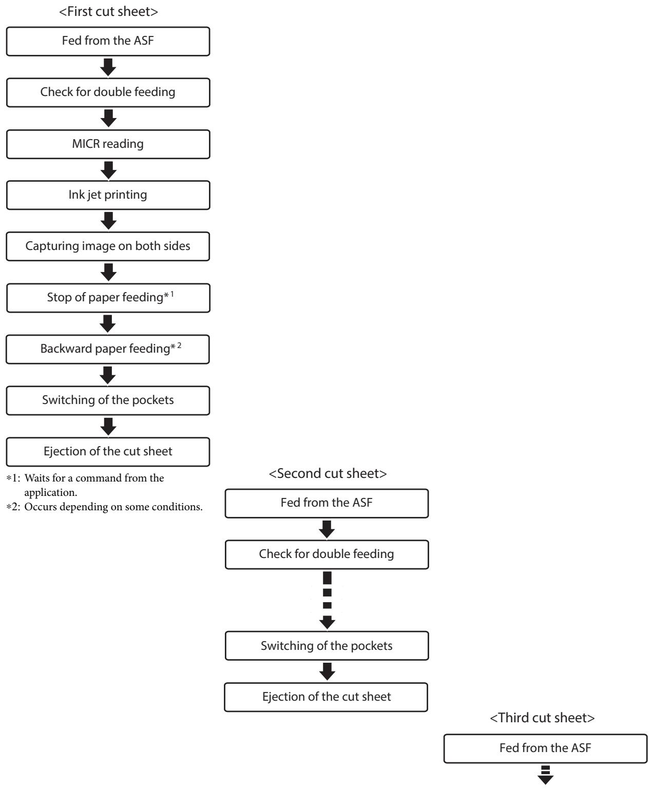
Confirmation Mode
Use this mode to specify processing conditions from the application.
This mode stops the process that starts with cut sheet feeding is from the ASF and ends with cut sheet output to a pocket, in order to receive an instruction from the application. It then restarts the process. It also can be used to configure the no-overlap/overlap setting from the application.

No-overlap: Starts send of the next cut sheet after the current cut sheet is fully in the pocket Overlap: Starts feeding of the next cut sheet while the current cut sheet is being output to the pocket
Document Processing Sequence
The processing sequence depends on the number of pockets and whether or not back feeding or overlap is being performed.
With overlap
When back feeding is not necessary with 1-pocket models/2-pocket models
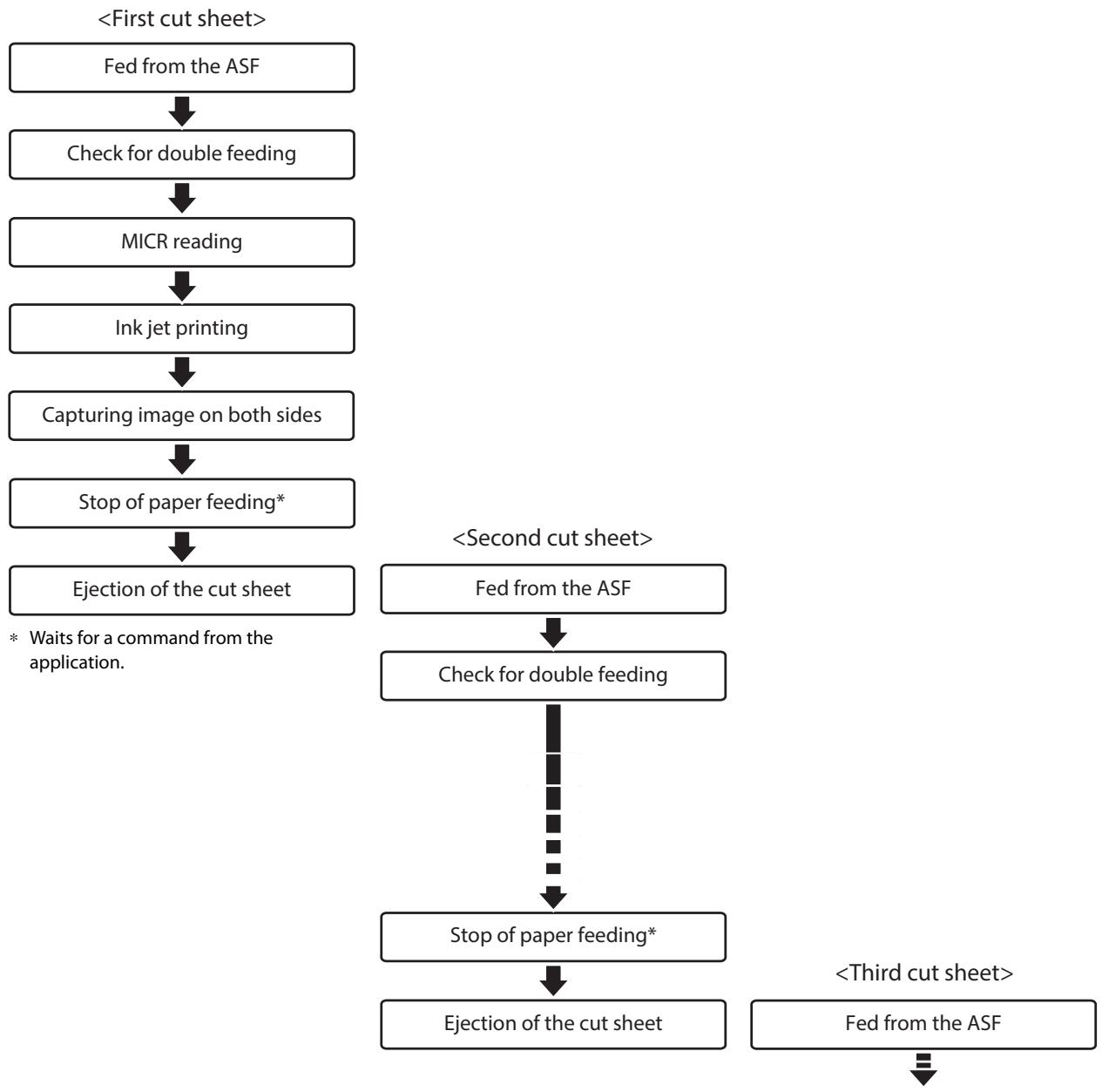
flowchart
graph TD
    A["First cut sheet"] --> B["Fed from the ASF"]
    B --> C["Check for double feeding"]
    C --> D["MICR reading"]
    D --> E["Ink jet printing"]
    E --> F["Capturing image on both sides"]
    F --> G["Stop of paper feeding*"]
    G --> H["Ejection of the cut sheet"]
    H --> I["* Waits for a command from the application."]

    J["Second cut sheet"] --> K["Fed from the ASF"]
    K --> L["Check for double feeding"]
    L --> M["Stop of paper feeding*"]
    M --> N["Ejection of the cut sheet"]
    N --> O["<Third cut sheet> Fed from the ASF"]
    O --> P["="]
With overlap
When back feeding is required with 2-pocket models
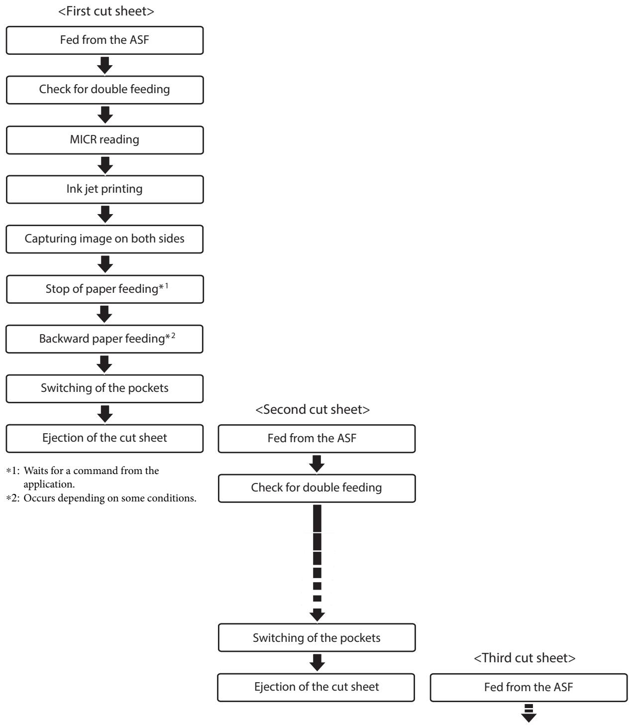
flowchart
graph TD
    A["<First cut sheet>"] --> B["Fed from the ASF"]
    B --> C["Check for double feeding"]
    C --> D["MICR reading"]
    D --> E["Ink jet printing"]
    E --> F["Capturing image on both sides"]
    F --> G["Stop of paper feeding*1"]
    G --> H["Backward paper feeding*2"]
    H --> I["Switching of the pockets"]
    I --> J["Ejection of the cut sheet"]

    K["<Second cut sheet>"] --> L["Fed from the ASF"]
    L --> M["Check for double feeding"]
    M --> N["Switching of the pockets"]
    N --> O["Ejection of the cut sheet"]

    P["<Third cut sheet>"] --> Q["Fed from the ASF"]
    Q --> R["End"]

    style A fill:#f9f,stroke:#333
    style B fill:#f9f,stroke:#333
    style C fill:#f9f,stroke:#333
    style D fill:#f9f,stroke:#333
    style E fill:#f9f,stroke:#333
    style F fill:#f9f,stroke:#333
    style G fill:#f9f,stroke:#333
    style H fill:#f9f,stroke:#333
    style I fill:#f9f,stroke:#333
    style J fill:#f9f,stroke:#333
    style K fill:#f9f,stroke:#333
    style L fill:#f9f,stroke:#333
    style M fill:#f9f,stroke:#333
    style N fill:#f9f,stroke:#333
    style O fill:#f9f,stroke:#333
    style P fill:#f9f,stroke:#333
    style Q fill:#f9f,stroke:#333
Without overlap
When back feeding is not necessary with 1-pocket models/2-pocket models
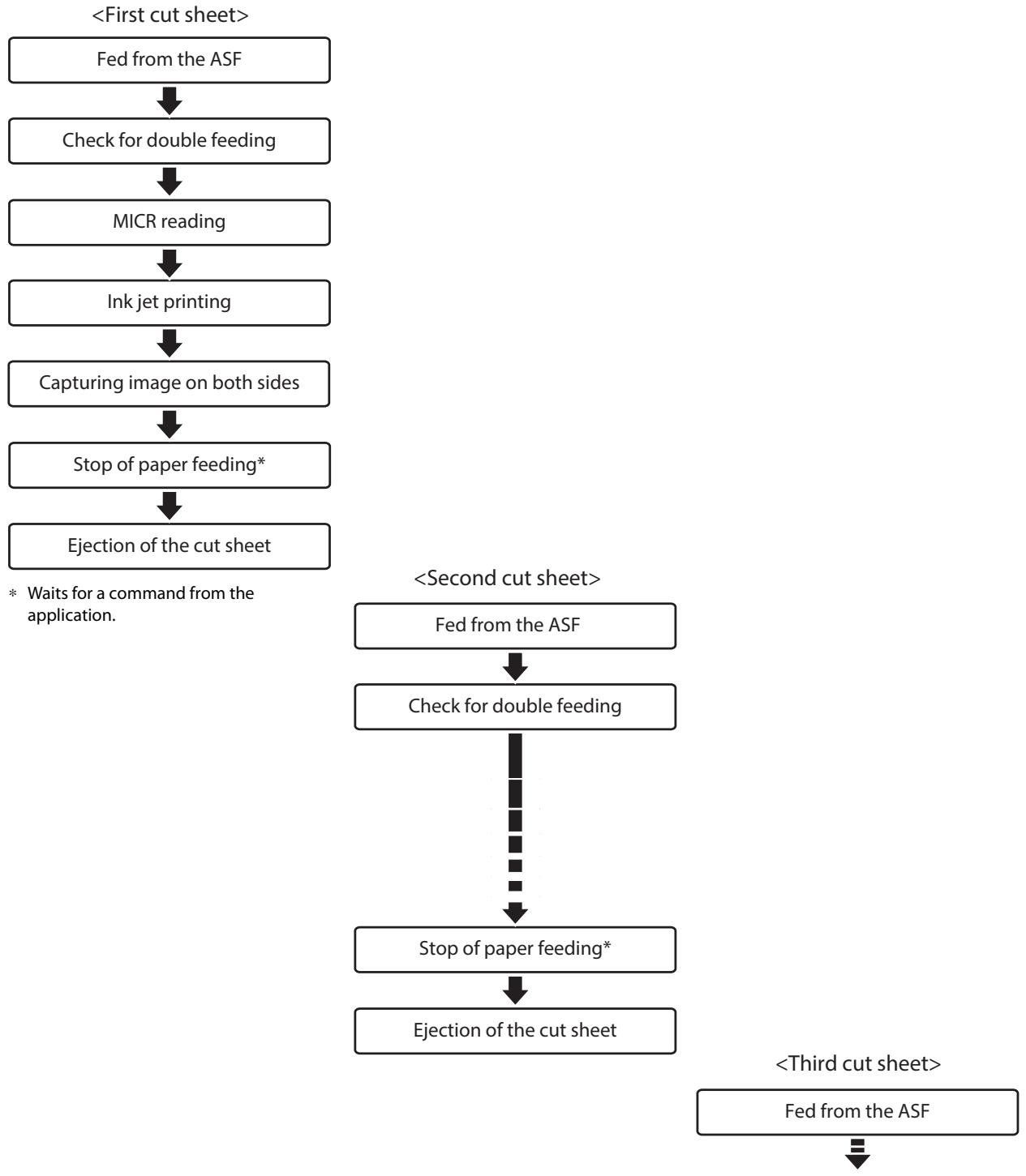
flowchart
graph TD
    A["<First cut sheet>"] --> B["Fed from the ASF"]
    B --> C["Check for double feeding"]
    C --> D["MICR reading"]
    D --> E["Ink jet printing"]
    E --> F["Capturing image on both sides"]
    F --> G["Stop of paper feeding*"]
    G --> H["Ejection of the cut sheet"]
    H --> I["<Second cut sheet>"]
    I --> J["Fed from the ASF"]
    J --> K["Check for double feeding"]
    K --> L["Stop of paper feeding*"]
    L --> M["Ejection of the cut sheet"]
    M --> N["<Third cut sheet> Fed from the ASF"]
    N --> O["End"]
    style A fill:#f9f,stroke:#333
    style O fill:#f9f,stroke:#333
With overlap
When back feeding is required with 2-pocket models
flowchart
graph TD
    A["<First cut sheet>"] --> B["Fed from the ASF"]
    B --> C["Check for double feeding"]
    C --> D["MICR reading"]
    D --> E["Ink jet printing"]
    E --> F["Capturing image on both sides"]
    F --> G["Stop of paper feeding*¹"]
    G --> H["Backward paper feeding*²"]
    H --> I["Switching of the pockets"]
    I --> J["Ejection of the cut sheet"]

    K["<Second cut sheet>"] --> L["Fed from the ASF"]
    L --> M["Check for double feeding"]
    M --> N["Switching of the pockets"]
    N --> O["Ejection of the cut sheet"]

    P["<Third cut sheet>"] --> Q["Fed from the ASF"]
    Q --> R["End"]

    style A fill:#f9f,stroke:#333
    style B fill:#f9f,stroke:#333
    style C fill:#f9f,stroke:#333
    style D fill:#f9f,stroke:#333
    style E fill:#f9f,stroke:#333
    style F fill:#f9f,stroke:#333
    style G fill:#f9f,stroke:#333
    style H fill:#f9f,stroke:#333
    style I fill:#f9f,stroke:#333
    style J fill:#f9f,stroke:#333
    style K fill:#f9f,stroke:#333
    style L fill:#f9f,stroke:#333
    style M fill:#f9f,stroke:#333
    style N fill:#f9f,stroke:#333
    style O fill:#f9f,stroke:#333
    style P fill:#f9f,stroke:#333
    style Q fill:#f9f,stroke:#333
Speed of Each Processing Mode
This is the processing speed from the point that the first cut sheet is sent from the ASF until receipt of the image data of the 100th cut sheet (highest value).
Processing Speed Conditions
The processing speed may be reduced by the conditions described below.
- Host computer operating environment (☐ “Operating Environment” on page 51)
- Software that coexists on the computer
• Image resolution, light source settings
When the resolution of the captured image is 240 dpi or 300 dpi, or when the acquired image is 24-bit color or infrared (IR)
- Driver IQA, OCR, bar code recognition settings
• Data transfer, save, and other application processing - Cut sheet status
- Processing mode and judgment subject
| Processing modes | Judgment made by | Condition details |
| High-speed mode | Firmware | Operation based on firmware judgments, without instruction from the host computer, for high-speed processing. However, when cut sheets are output to the sub-pocket in the case of 2-pocket models, processing is slower due to generation of back feeding. |
| Driver | When driver judgment is required, processing speed is slower compared to operation according to judgment conditions by firmware only. | |
| Confirmation mode | Application | Since the product stands by for instructions from the application for each cut sheet scan, processing speed depends on control from the application. Also, processing speed depends on whether or not overlap is performed. |
Processing Modes
Resolution of captured image: 200 dpi, grayscale/black and white
| Processing mode and judgment subject | Media size | Processing speed | |||
| 225 DPM | 130 DPM | ||||
| Main-pocket ejection | Sub-pocket ejection 50%*1 | Main-pocket ejection | Sub-pocket ejection 50%*1 | ||
| High-speed mode Firmware judgment | Personal check | 225 DPM | 106 DPM | 130 DPM | 92 DPM |
| Business check | 175 DPM | 84 DPM | 130 DPM | 78 DPM | |
| High-speed mode Driver judgment | Personal check | 94 DPM | 71 DPM | 94 DPM | 71 DPM |
| Business check | 82 DPM | 60 DPM | 82 DPM | 60 DPM | |
| Confirmation mode*2 Application judgment | Personal check | 73 DPM | 59 DPM | 73 DPM | 59 DPM |
| Business check | 59 DPM | 48 DPM | 59 DPM | 48 DPM | |
*1: When 50 of the 100 sheets are in the sub-pocket
*2: Does not take application processing time into consideration
NV Memory
This product is equipped with nonvolatile memory (NV), which maintains stored data even if the product is turned off. The memory areas below are available in NV memory for use by the user.
- NV graphics memory
- NV user memory
- Memory switch
- User-defined page
- Maintenance counters
CAUTION
As a general rule for the number of writes to NV memory, create an application that writes no more than 10 times a day.
NV Graphics Memory
Multiple store logos and other graphics can be registered for printing on logos.
Registered graphics can be viewed using the TM-S2000II Utility or the NV graphics information print mode.
NOTE
For details on the NV graphics information printing mode, refer to the TM-S2000II Utility User's Manual and "NV Graphics Information Print Mode" on page 50.
NV User Memory
Custom product settings and maintenance information can be saved as text data and read as required.
Memory Switch
This switch can be used to configure various product settings.
For details on memory switches, refer to “Software Settings” on page 45.
User-defined Page
Character that is not registered on the product can be printed by registering it on a user-defined page (Character Code Table: page 255).
Maintenance Counters
This function automatically registers the number of print lines, the number of auto cutter operations, product running time, and other maintenance counter information in product memory. Counter information can be referenced to support periodic inspections, consumable replacement and others.
NOTE
The head travel distance and the number of auto cutter operations (☐ "Self-test Mode" on page 49).
Setup
This chapter describes the product and peripheral device installation and setup procedures that need to be performed before using the product.
Setup Flow
The information in this chapter follows the flow of product and its peripheral device setup as shown below.
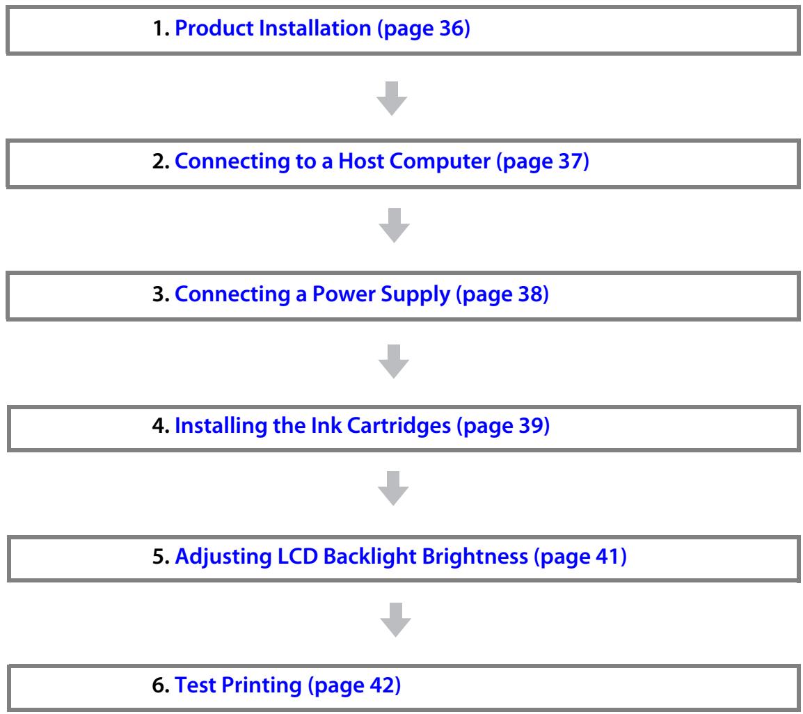
flowchart
graph TD
    A["1. Product Installation (page 36)"] --> B["2. Connecting to a Host Computer (page 37)"]
    B --> C["3. Connecting a Power Supply (page 38)"]
    C --> D["4. Installing the Ink Cartridges (page 39)"]
    D --> E["5. Adjusting LCD Backlight Brightness (page 41)"]
    E --> F["6. Test Printing (page 42)"]
Product Installation
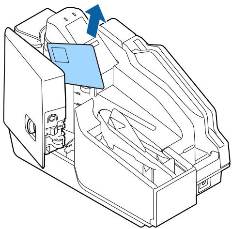
Removing the Packing Materials
Packing materials are affixed for protection against shock during transportation. Remove the packing materials shown below before installing the product.
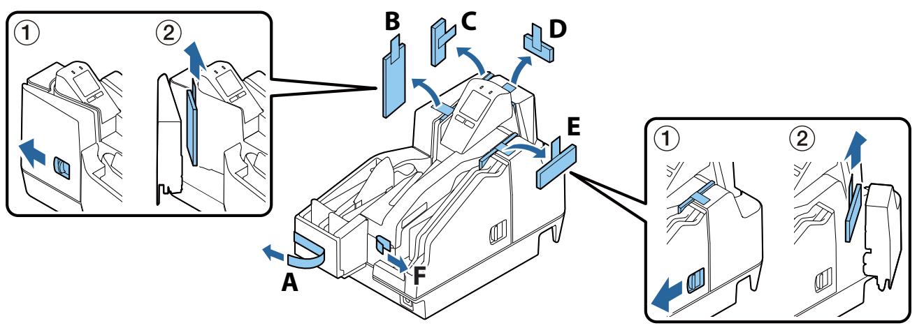
NOTE
The packing materials and packaging box are required for future transportation. Keep them in a safe place.
Installation
Provide sufficient space in a location appropriate for installation.
Location Appropriate for Installation
- On an area larger than the bottom surface of the product (☐ “Overall Dimensions” on page 92)
• In a level and stable location - In a location free of vibration and impacts
- In a location where a dedicated power outlet is available
- In a location with sufficient space around the printer to allow for replacement of consumable products, and daily cleaning
- In a location meeting the guaranteed environmental conditions (“Environmental Specifications” on page 91)
CAUTION
- When moving the product, lift it up by grasping at the depressions on either side.
- Make sure that cords or other objects are not being pinched by the product.
- To avoid deterioration of the MICR recognition rate, do not install the product near a magnetic field. In particular, check the MICR reader recognition rate when the product is installed near a display device.
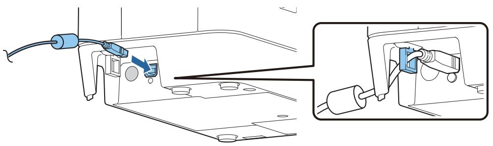
Connecting to a Host Computer
Connect the USB for connecting with the host computer to the port on the back of the product. (☐ “Rear” on page 18)

• Pass the USB cable through the wire saddle to prevent accidental disconnection.
- Use of the included USB cable is recommended. Use of another USB cable can result in improper operation during large-volume data processing when scanning a series of documents.
natural_image
Technical diagram showing cable installation and connection to a mechanical component (no text or symbols)Connecting a Power Supply

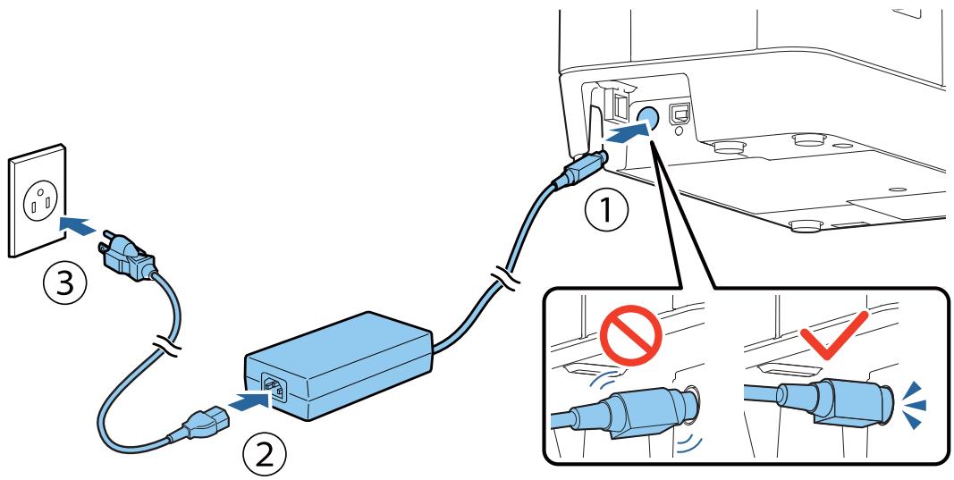
- Use only the specified AC adapter. Not doing so may cause a fire or electric shock. (☐ "Electrical Specifications" on page 80)
- Do not plug the AC cable into a power outlet whose voltage does not match the input voltage of the AC adapter. Doing so can damage the product.
- If you discover an abnormality immediately turn off the product and unplug AC cable from the power outlet.
- Use only the AC cable that comes with the product.
1 Insert the DC connector of the AC adapter firmly all the way into the DC-IN connector of the product.
2 Insert the connector of the AC cable firmly all the way into the AC inlet of the AC adapter.
3 Insert the power plug firmly all the way into an outlet with a ground.
4 Place the AC adapter with its label facing downward.
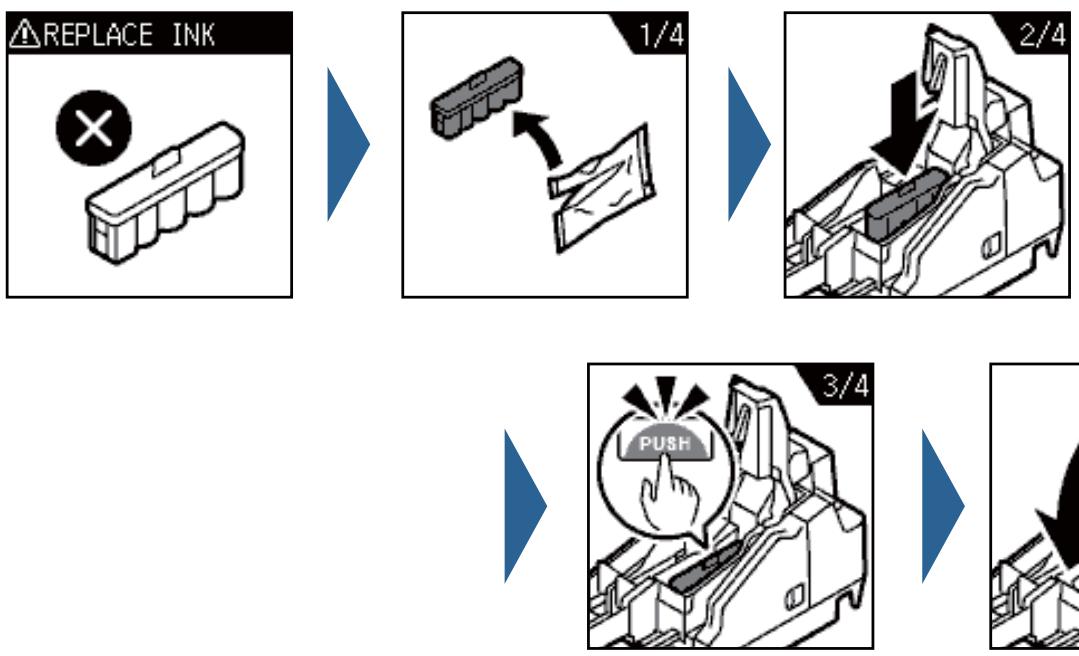
Installing the Ink Cartridges
This section describes the procedure for installing the ink cartridges and performing ink charging for the first time.
When replacing an ink cartridge, refer to “Replacing the Ink Cartridges” on page 59, and then follow the procedure in this section.

CAUTION
Read the precautions on handling carefully before installing the ink cartridges.
("Cautions on Ink Cartridges" on page 9)
1 Check that the product is powered on. ( "Turning the Power On" on page 57)
2 Open the ink cartridge cover. ( "Opening the Ink Cartridge Cover" on page 58)
3 Remove a new ink cartridge from its bag.
4 Peel the yellow film from the ink cartridge.


CAUTION
- Do not remove the other label.
- Do not touch the IC chip.
5 Gently press the ink cartridge into the product.
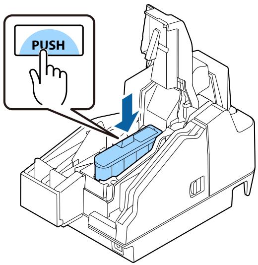
6 Close the ink cartridge cover.
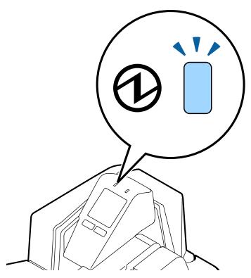
Ink charging starts. The ① (POWER) LED flashes during ink charging. It takes up to 4 minutes to charge the ink the first time ink cartridges are installed in the product.
When ink charging completes, the ① (POWER) LED changes from flashing to on.

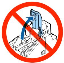
Never open any cover of the printer or turn off the printer during ink charging (while the ① (POWER) LED is flashing). Doing so will consume a large amount of ink, which may result in the need to replace the ink cartridges before the completion of charging.
natural_image
Illustration of a device with a battery symbol and a lightbulb, no text or symbols present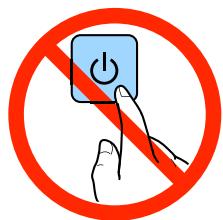
NOTE
The ink cartridges included in the product package are used for initial charging. The product uses ink to prepare for printing (ink charging) when the ink cartridges are installed for the first time.
The installing of ink cartridges is now complete.
Adjusting LCD Backlight Brightness
Adjust the brightness of the LCD to suit the environment where the product is being used. The changed setting is retained even if the power is turned off. Available brightness settings are bright, normal, and dark.
1 Open the ink cartridge cover. ( "Opening the Ink Cartridge Cover" on page 58)
2 Press Button 1 (dark) to make the display dark, or Button 2 (bright) to make the display bright.
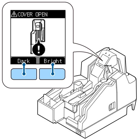
3 Close the ink cartridge cover.
Test Printing
Self-test printing can be used to check product settings. Self-test printing on cut sheets can be used to check for missing dots and other printing irregularities.
For printing procedure, refer to “Self-test Mode” on page 49.
Firmware version 1.02 ESC/POS
Buffer Capacity 4K bytes (fixed)
Handshaking operation (busy condition) Receive buffer full (fixed)
Automatic line feed (CR command function) Disabled
Resident character Alphanumeric
Power on status Disabled
Receipt cover open Auto recoverable error
Remote wakeup Enabled
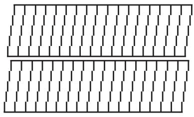
Nozzle check pattern
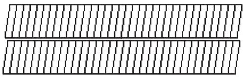
natural_image
Pure geometric pattern with diagonal lines and a horizontal bar (no text or symbols)Maintenance information
Thermal head : 0.000 km
Autocutter : 1 cut
Inkjet head(nozzle1): 234 shots
Inkjet head(nozzle1): 130 shots
MICR head : 92 sheets
Memory switches
If the test print shows that the nozzle check pattern is blurred, it means that ink head cleaning is required.
( "Ink Head Cleaning" on page 65)
natural_image
Pure geometric pattern of vertical lines within rectangular blocks (no text or symbols)
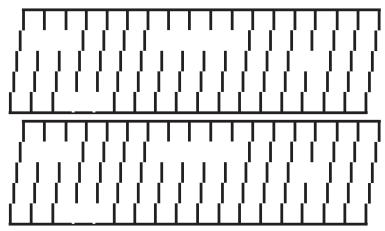
natural_image
Two parallel rectangular patterns with vertical dashed lines, no text or symbols presentAdvanced Product Use
Software Settings
The product has memory switches and customize values as software setting functions, which can be used for configuring various product settings.
Refer to the following section for an overview of each function. Settings are configured using the TM-S2000II Utility.
NOTE
For details on the TM-S2000II Utility, refer to the TM-S2000II Utility User's Manual.
Function
Transmits the power ON information
- No send (default setting)
- Send
Auto line feed
• Always disabled (default setting)
- Always enabled
Remote wake-up
- Enabled (default setting)
- Disabled
Sets time to check ink head cleaning
Time (hh:mm) can be specified
Default setting: 20:00
Validation settings
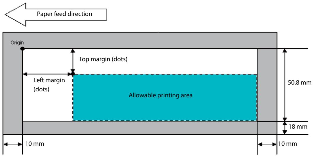
Top margin (default setting: 0) and left margin (default setting: 0) settings are configurable
Cut sheet settings
Top margin (default setting: 0) and left margin (default setting: 0) settings are configurable
Time to enter power saving mode
This time can be set within the range of 100 ms [0.1 second] to 3600 s [60 minutes]
Default setting: 300 s [5 minutes]
Function to prevent printing on the back side of documents (endorse) without magnetic ink characters
- Disabled (default setting)
- Enabled
Magnetic ink characters appearance judgment position
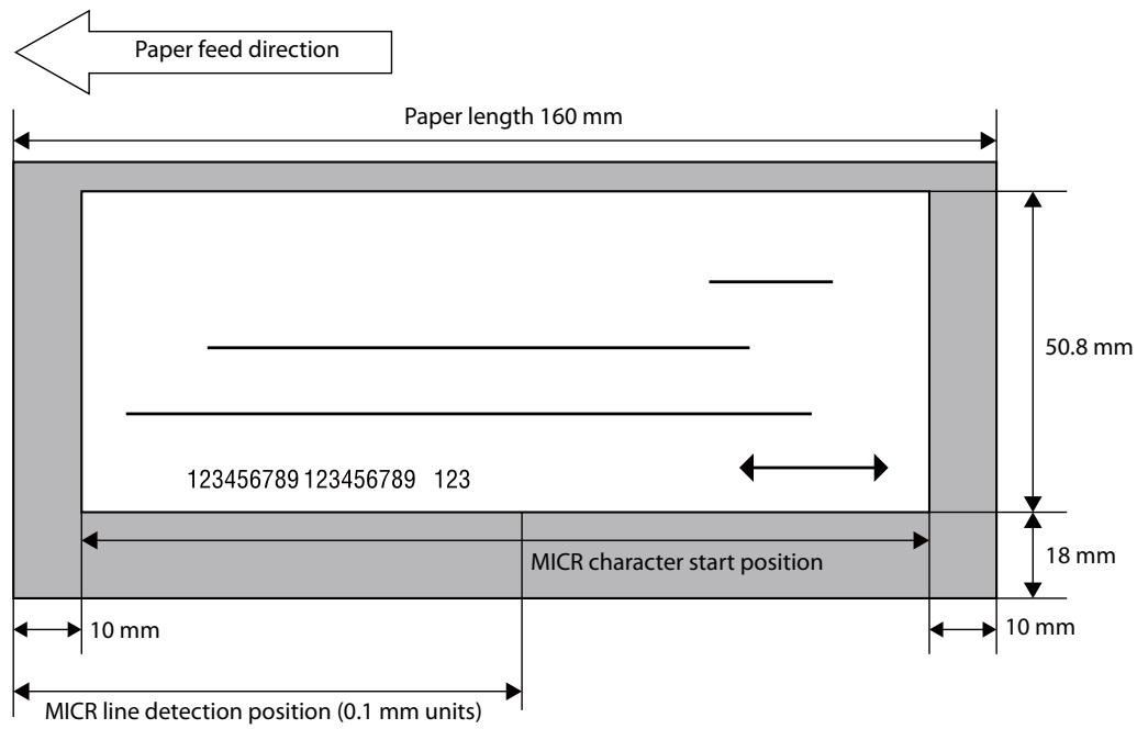
The MICR line judgment location (default: 0) can be specified in 0.1 mm units
Setting/Confirmation Mode
In addition to the normal printing modes, the product also includes the modes below for configuring settings and checking the status of functions.
- Self-test mode
• NV graphics information print mode
Each mode is selected in accordance with the button that is pressed when the product is turned on and whether a cover is opened or closed.
flowchart
graph TD
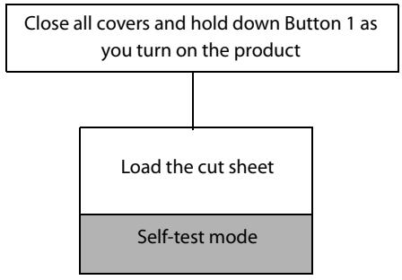
A["Close all covers and hold down Button 1 as you turn on the product"] --> B["Load the cut sheet"]
B --> C["Self-test mode"]
flowchart
graph TD
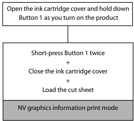
A["Open the ink cartridge cover and hold down Button 1 as you turn on the product"] --> B["Short-press Button 1 twice + Close the ink cartridge cover + Load the cut sheet"]
B --> C["NV graphics information print mode"]
Self-test Mode
You can use the self-test to check the items below.
• Control circuit function
• Printer mechanism function
- Print quality
• Control ROM version
• Memory switch setting function
For self-test printing, use the included cut sheet paper or cut sheets with dimensions of at least 70 mm wide by 152 mm long.
1 Turn off the product and confirm that all covers are closed.
2 While holding down Button 1, press the ⏻ (POWER) button to turn on the product.
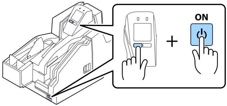
3 Load three cut sheets into the ASF. ( "Loading Cut Sheets" on page 61) Test printing begins. Printing is complete when "*** completed ***" is printed.
NOTE
- Self-test printing uses three cut sheets. The product stands by for insertion of cut sheets until printing is complete.
- If the check doesn't feed correctly, perform the self-test using 3 of the provided new cut sheets. If the printer has not been used for three months or more, please perform this self-test print procedure, and repeat until the unit feeds correctly.
NV Graphics Information Print Mode
This mode prints the NV graphics information below, which is registered on the product.
• NV graphics capacity
• NV graphics capacity usage
• NV graphics remaining free space
• NV number of graphics registrations
• Key code of each data, X-direction dots and Y-direction dots
- NV graphics data
NOTE
For details on NV graphics, refer to "NV Memory" on page 33.
For self-test printing, use the included cut sheet paper or cut sheets with dimensions of at least 70 mm wide by 152 mm long.
1 Turn off the product and open the ink cartridge cover.
2 While holding down Button 1, press the ⏻ (POWER) button to turn on the product.
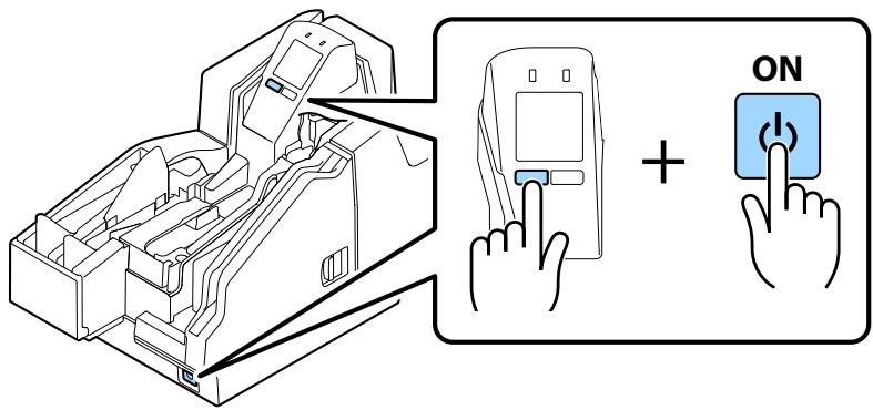
3 Press Button 1 twice.
4 Close the ink cartridge cover. This starts printing of NV graphics information.
NOTE
Initialization starts after printing is complete. Next, the product transitions to its normal state (printing/scanning enabled).
Application Development Information
This chapter describes product control methods and the information required to develop applications used by the product.
Operating Environment
The operating environment required to get the most out of the product's basic specifications depends on the model.
130 DPM Model
• CPU: At least a Intel Pentium 4 2.0 GHz or the equivalent
- Memory: At least 512 MB or above the minimum operating system requirement
- HDD: Free space of more than 30 MB (Before installing the driver)
• I/F: USB2.0 Hi-speed
225 DPM Model
• CPU: At least Intel Core 2 Duo 1.8 GHz or the equivalent
- Memory: At least 1 GB or above the minimum operating system requirement
- HDD: Free space of more than 30 MB (Before installing the driver)
• I/F: USB2.0 Hi-speed
Driver
The drivers described below are available for application development.
For detailed information on functions and support environments, refer to the documentation that comes with each driver.
For Windows Environment
• EPSON TM-S2000 Driver
Use the API (application interface) to implement product functions. Development can be performed using Visual C++, Basic, and other programming languages.
• EPSON TM-S2000 TWAIN Driver
This driver is for control of products that use TWAIN, which is a standard interface for scanners.
• EPSON Windows Printer Driver for TM-S2000
This is a standard printer driver for Windows.
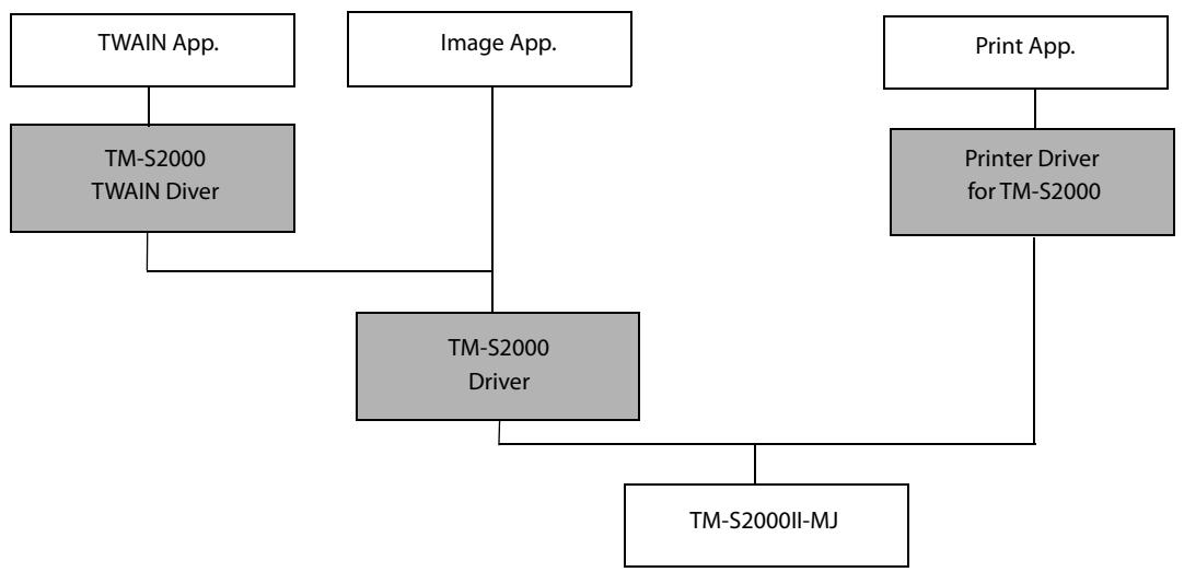
flowchart
graph TD
    A["TWAIN App."] --> B["TM-S2000 TWAIN Diver"]
    C["Image App."] --> D["TM-S2000 Driver"]
    E["Print App."] --> F["Printer Driver for TM-S2000"]
    B --> D
    D --> G["TM-S2000II-MJ"]
List of Supported Functions
√: Supported -: Unsupported
| Function/driver | EPSON TM-S2000 Driver | EPSON TM-S2000 TWAIN Driver | EPSON Windows Printer Driver for TM-S2000 |
| Scanning cut sheet | √ | √ | - |
| Reading MICR characters on a check | √ | √ | - |
| Endorsement printing of a check | √ | √ | - |
| Electronic endorsement printing | √ | √ | - |
| Scanning ID Cards | √ | √ | - |
| Printing on cut sheet | √ | - | √ |
| MSR* | - | - | - |
* : The equipped MSR is a USB HID-Keyboard interface
For Linux Environment
• EPSON SANE for TM-S2000
This is software for controlling products that use the main scanner interface for Linux.
• EPSON CUPS for TM-S2000
Printer driver for Linux.
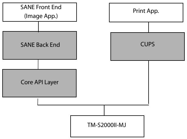
flowchart
graph TD
    A["SANE Front End (Image App.)"] --> B["SANE Back End"]
    B --> C["Core API Layer"]
    D["Print App."] --> E["CUPS"]
    E --> F["TM-S2000II-MJ"]
List of Supported Functions
√: Supported -: Unsupported
| Function/driver | EPSON SANE for TM-S2000 | EPSON CUPS for TM-S2000 |
| Scanning cut sheet | √ | - |
| Reading MICR characters on a check | √ | - |
| Endorsement printing of a check | √ | - |
| Electronic endorsement printing | √ | - |
| Scanning ID Cards | √ | - |
| Printing on cut sheet | - | √ |
| MSR* | - | - |
* : The equipped MSR is a USB HID-Keyboard interface
Utilities
The utilities described below are available for application development.
For details about functions and support environments, refer to the documentation that comes with each driver.
TM-S2000II Utility
This utility is for checking and modifying each of the product's internal values.
It has the following functions:
- Current settings
- Storing logos
- Printing control
- Backup/restore
- Operation test
- MSR setting (Specifies the processing method for read data.)
Epson Deployment Tool
This tool can be used to change product settings and printer driver settings. The settings of multiple products can be configured simultaneously, which reduces work time.
Downloading Software
Download the latest version of each software from the URLs below.
For customers in North America, go to the following web site: http://www.epson.com/support/
For customers in other countries, go to the following web site: https://download.epson-biz.com/?service=pos
Handling the Product
This chapter describes the basic handling procedures for the product.
Turning On/Off
This section describes how to turn the product on/off.
Turning the Power On
Hold down the ⏻ (POWER) button for at least 1 second until the ⏱ (POWER) LED turns on.
natural_image
Technical line drawing of a mechanical component with internal compartments and mounting holes (no text or symbols)
(POWER) button
Turning the Power Off
Hold down the ⏻ (POWER) button for at least 3 second until the ⏱ (POWER) LED turns off.
To turn off power without using the ⏻ (POWER) button, send the command that executes the power off sequence.

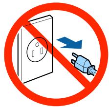
- Do not remove and insert the power plug from/to the outlet while the power of the product is in the on state. Doing so may cause electric shock or fire.
- Turning off the product by performing a ⏻ (POWER) button operation or by sending a command causes the ink head to be capped automatically to prevent the ink from drying. If you do not plan to use the product after installing an ink cartridge, be sure to use either of the methods above to turn off power. Do not pull out the power plug or turn off the breaker while the power is on.
Opening a Cover
This section describes how to open each of the product's covers.
Opening the Ink Cartridge Cover
Use your finger to lift up the tab on the ink cartridge cover, and pull up to open the cover.
natural_image
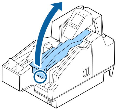
Diagram of a mechanical device interior with blue arrows indicating flow or movement, no text or symbols presentOpening the MICR Cover or Scanner Cover
Pull the cover lever and then swing the cover outwards to open it.
natural_image
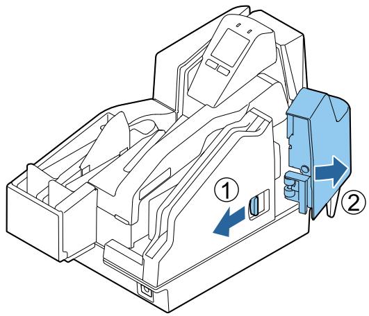
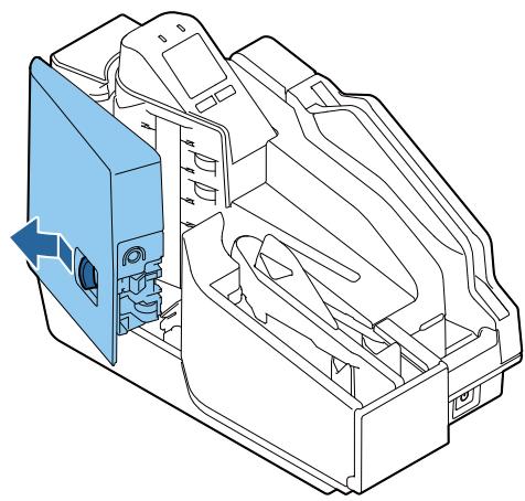
Technical line drawing of a mechanical housing or enclosure with internal compartments and a blue component (no text or symbols)Replacing the Ink Cartridges
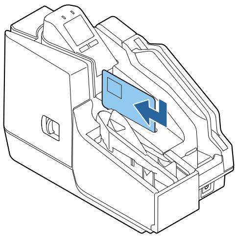
If the LCD displays the animation shown below, it is time to replace the ink cartridge.
natural_image
Mechanical component diagram showing a lever mechanism with no visible text or symbolsFor the replacement procedure, refer to “Installing the Ink Cartridges” on page 39. Replacement can be performed with the same procedure. Grasping the tab on the top side of the used ink cartridge, pull it out to remove it.
For the model numbers of the ink cartridges, refer to “Ink Cartridge” on page 80.
Cut Sheet Processing
This section describes cut sheet processing.
Process Flow
The processing flow below is performed by the product, from the point cut sheets are loaded in the ASF until they are ejected to a pocket.
| 1 | Cut sheet feed |
| Inserted cut sheets are separated one-by-one and fed. | |
| 2 | MICR reading |
| Reads the magnetic ink characters printed on checks. | |
| 3 | |
| Prints on cut sheets. | |
| 4 | Scanning |
| Reads both sides of cut sheets. | |
| 5 | Eject/store |
Processed cut sheets are ejected and stored.
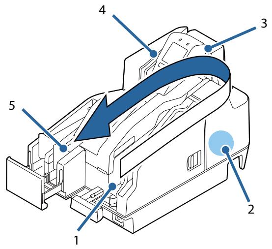
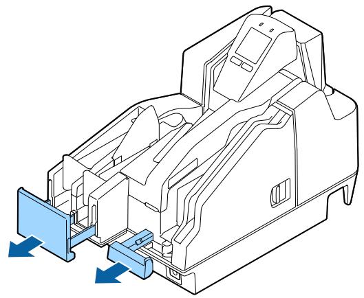
Loading Cut Sheets
Use the procedure below to load cut sheets.
Up to 100 cut sheets can be loaded in the ASF.
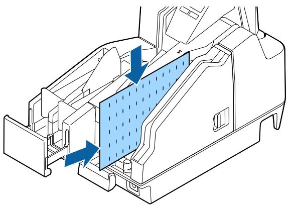
1 Pull out the ASF guide and pocket guide to match the length of the paper.
natural_image
Technical line drawing of a mechanical assembly with blue directional arrows indicating movement or force (no text or symbols present)2 Load the cut sheets so they are aligned with the ▲ mark on the top of the ink cartridge cover.
When reading MICR characters, load the sheets so the magnetic ink characters are facing away from and toward the bottom of the product. When loading multiple sheets, first align them on their lower right corners.
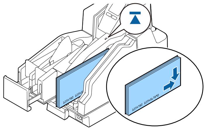

Note the precautions below. Failure to satisfy these conditions can result in cut sheet reading not starting or cause jamming.
- Use cut sheets that conform to product specifications
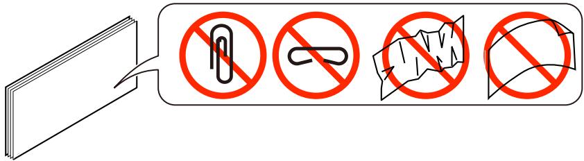
- Make sure there are no clips on or stables in the cut sheets, and make sure that the cut sheets are not curled, bent or wrinkled
3 Load the paper and remove your hand.

After paper ejection is complete, remove it by hand. Touching the paper or opening the cover while processing is in progress creates the risk of paper jams or unexpected injury.
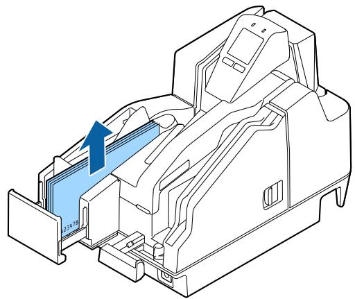
Removing Cut Sheets
After cut sheets are ejected into the pocket, remove them.
natural_image
Technical line drawing of a mechanical device interior with internal components and a blue arrow indicating direction (no text or symbols)CAUTION
- Each of the pockets can store the number of sheets shown below. To prevent paper jams, do not allow the number of sheets in a pocket to exceed the specified value.
- Main pocket: 100
- Sub-pocket: 50
- Paper feed speed is lower in the case of 300 dpi color image acquisition or simultaneous acquisition of a color image and IR image. Depending on the paper type and conditions, cut sheets may curl in the pocket at this time. Because of this, it is recommended that cut sheets be removed after about 25 sheets are accumulated in the pocket.
ID Card Processing
This section describes ID card processing.
CAUTION
Note the precautions below. Failure to do so can cause ID card reading problems.
- Use ID cards in accordance with specifications.
- Check to make sure that ID cards are not bent, broken, or excessively embossed.
- Do not touch the IC chip of the ID card.
- Do not open a cover, touch the ID card, or block the slot while the product is processing an ID card.
1 Insert the ID card into the slot and slide it.
natural_image
Technical line drawing of a mechanical device interior with no visible text or symbols2 Release the ID card after it starts to be fed automatically.
3 After the ID card is ejected, remove it.
natural_image
Technical line drawing of a mechanical device interior with a blue arrow indicating direction (no text or symbols)Magnetic Stripe Card Processing
This section describes magnetic stripe card processing.
NOTE
Some models are not equipped with a magnetic stripe card reader (MSR).
CAUTION
Use magnetic stripe cards that conform to product specifications.
Insert the card into the slot so its magnetic stripe is facing toward the product and downward, and then slide downward or upward in the slot. At this time, press down on the card to make sure it is sliding along the bottom of the card slot.
The buzzer sounds once if reading is successful, and three times if it fails.
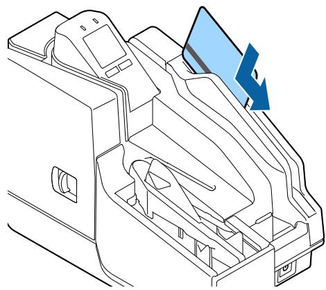
natural_image
Technical line drawing of a mechanical component with a blue arrow indicating direction (no text or symbols)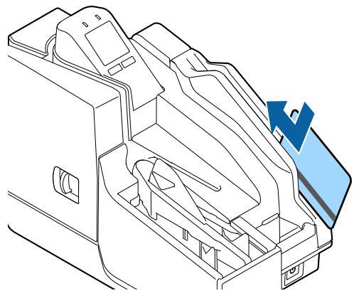
natural_image
Technical line drawing of a mechanical component with internal cavities and a blue arrow indicating direction (no text or symbols)Cleaning the Product
Cleaning the Exterior
After turning of the product, use a slightly damp cloth to wipe it off. Before doing so, be sure to unplug the AC cable from the power outlet.

Do not use alcohol, benzine, thinner, trichloroethylene, or ketone based solvent to clean the exterior of the printer.
Doing so may deform or damage the plastic and rubber parts.
Ink Head Cleaning
If printing becomes blurred or uneven, even though there is sufficient ink remaining, it means that the ink head needs cleaning.
On the LCD home screen, press the Cleaning button (Button 1). This will display a confirmation message. Press the Yes button (Button 2) to perform the cleaning operation.
This starts cleaning and causes the ⑪ (POWER) LED to flash. The ⑫ (POWER) LED stops flashing when cleaning is complete.

Do not turn off the product or open a cover while cleaning is in progress (① (POWER) LED flashing).

- Do not run the head cleaning more than necessary. Ink is consumed because ink is discharged from the head to clean it.
- If there is not enough ink remaining, head cleaning may not be possible. Replace the ink cartridges and then try again.
Cleaning the Paper Feeding Path
If there are problems correctly reading the magnetic ink characters of a check, cleaning of the paper feeding path using a commercially available cleaning kit is required. Periodic cleaning is recommended. The cleaning period is once a week or every 2,000 checks.
Use either of the methods below to perform cleaning.
• Cleaning using the application
- Cleaning using the printer (☐ “Cleaning Using the Printer” on page 67)
Cleaning kit model numbers
KIC Team, Inc.
- Waffletechnology® MICR cleaning card (model:CS1B15WS)
- Epson Check Scanner Cleaning Kit (model:KWEPS-KCS2)
Cleaning Using the Application
Turn on the product and insert a cleaning sheet into the ASF. Use the application to execute a paper feed, which passes the cleaning sheet along the paper path and cleans it.
natural_image
Technical diagram of a mechanical assembly with blue arrows indicating flow or movement, no visible text or symbolsCleaning Using the Printer
Use the procedure below to perform cleaning.
1 Turn off the product and open the ink cartridge cover.
2 While holding down Button 1, press the ⏻ (POWER) button to turn on the product.
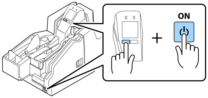
3 Press Button 1 three times.
4 Close the ink cartridge cover.
5 Insert a cleaning sheet into the ASF.

natural_image
Technical line drawing of a vehicle interior showing structural components and airflow direction (no text or symbols)Feed the cleaning card to clean the paper path.
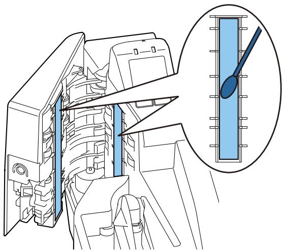
Cleaning the Scanner
If the quality of data read from cut sheets or ID cards is poor, scanner cleaning is required. Periodic cleaning is recommended. The cleaning period is once a week or every 2,000 checks.
Turn off the product and open the scanner cover. Gently wipe the glass using a soft, dry cloth.
CAUTION
- Do not use detergent, water, or other liquid for cleaning. Doing so creates the risk of dirt adhering to the glass.
- If oil, grease, or other similar matter gets on the scanner glass, wipe it with a cloth moistened with alcohol. However, make sure that liquid does not come into direct contact with the scanner glass.
natural_image
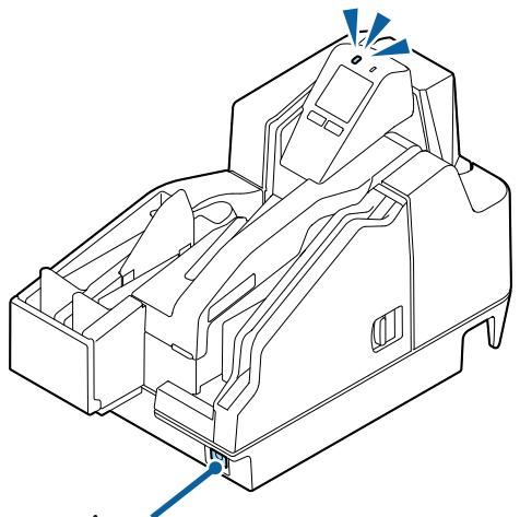
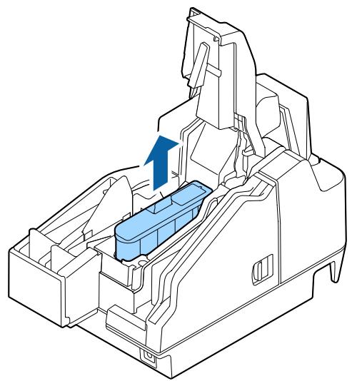
Technical line drawing of a mechanical assembly with an inset showing a blue tool interacting with a component (no text or symbols present)Preparing for Transport
Perform the steps below to prepare the product for transport.
CAUTION
Do not transport a used ink cartridge. Doing so may cause the ink to leak.
1 Turn off the power. ( "Turning the Power Off" on page 57)
2 Confirm that the ① (POWER) LED is unlit.
3 Disconnect the DC connector from the product.
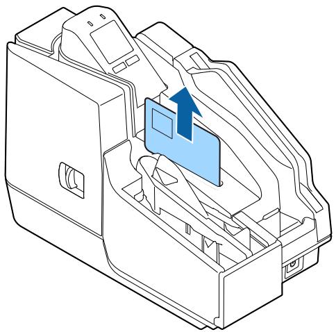
4 Remove the ink cartridge.
natural_image
Technical line drawing of a mechanical assembly with a blue component and directional arrow (no text or symbols)5 Store the ASF guide and pocket guide.
6 Pack the product so it is supported both from above and below.
Troubleshooting
This chapter describes how to resolve problems.
| Trouble | Reference |
| The Product Does Not Turn On | page 72 |
| Lit or Flashing ! (ERROR) LED | page 72 |
| Error Message Displayed on the LCD | page 73 |
| Cut Sheet Jam | page 76 |
| ID Card Does Not Come Out | page 77 |
| Problems with Print Quality | page 78 |
| Problems with Reading Quality | page 78 |
The Product Does Not Turn On
Making sure each connector is oriented correctly, insert the power cable into the product and the power outlet as far as it will go. (☐ “Connecting a Power Supply” on page 38)
Lit or Flashing ! (ERROR) LED
If the ! (ERROR) LED is lit or flashing, check the message on the LCD for information on resolving the problem. (☐ “Error Message Displayed on the LCD” on page 73)
Error Message Displayed on the LCD
If a message appears on the LCD of the operation panel, try the solution described below.
There are two error types: recoverable error and unrecoverable error.
Recoverable Error
Product operation stops when a recoverable error occurs. After removing the cause of the error, you can return back to normal by turning power off and then back on again, or by using the error recovery command.
| LCD display | Error name | Error details | Solution |
 | Mechanism position error | The home position of the hopper or the pocket switching board cannot be detected. | Execute the error recovery command (DLE ENQ (n=2)) or turn power back on. |
 | |||
 | Cut sheet jam error | Even if cut sheets are sent a fixed amount, they are not ejected.This could be due to the reasons below.Paper feed from the ASF failedCut sheet jamming was detectedToo short or too long cut sheet was detected | If paper feed from the ASF failed:Load the cut sheets so they are aligned with the ▲ mark on the top of the ink cartridge cover.(∠ “Loading Cut Sheets” on page 61)If a cut sheet jam was detected:Remove the jammed paper and then re-load it into the ASF. (∠ “Cut Sheet Jam” on page 76)If a too short or too long cut sheet was detected:Use cut sheets in accordance with the specifications.(∠ “Paper Specifications” on page 86) |
 | |||
 | Cut sheet feed error | Double-feed of cut sheets.This could be due to the reasons below.Cut sheets were inserted upside down or backwardsConfirmation mode is configured so this condition causes an errorGeneration of noise by MICR was detectedSpecified print data is longer than the cut sheet length | If cut sheets were inserted upside down or backwards: Orient cut sheets correctly when loading them.(Loading Cut Sheets" on page 61)When the confirmation mode is configured so this condition causes an error: Follow the instructions provided by the application.When generation of noise by the MICR was detected: Scan again.When the specified print data is longer than the cut sheet length: Specify print data that is shorter than the length of the cut sheets. |
 | |||
 | Cartridge recognition error | Ink information writing is not be performed correctly. | Check if the ink cartridge is installed correctly.(Installing the Ink Cartridges" on page 39)Or you should replace the ink cartridge with a new one.(Replacing the Ink Cartridges" on page 59) |
Unrecoverable Error
When an unrecoverable error occurs, an error code appears on the LCD and product operation stops.
If turning the product off and then back on again does not clear the error, servicing is required.
| Error code | Error name | Error details |
| APA11 | CPU execution error | CPU is executing an illegal address. |
| AHB12AHB11 | Read/Write error | Normal operation is not performed following read/write check. |
| AKA41 | High-voltage error | Power supply voltage is high. |
| AKA42 | Low-voltage error | Power supply voltage is low. |
| AKA11AAA21AAF21AAF31AKA82AKA31AKA71 | Drive circuit error | Drive circuit error occurred. |
| AGB11AGA14AGC22AGD21AGD22 | IJ mechanism error | Ink jet mechanism error occurred. |
| AKA51 | Communication device error | USB error occurred. |
| AKA81 | Double-feed detector noise level error | Noise was detected by the double-feed detector. |
| AKA83 | Double-feed detector detection error | Double-feed detector error occurred. |
| BGA1FBGA31 | Maintenance error | The specified number of pump drives, or the specified absorber absorption volume has been exceeded. |
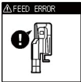
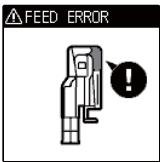
Cut Sheet Jam
Open the applicable cover and remove the jammed cut sheets. The location of the cut sheet jam can be determined by checking the LCD.
CAUTION
Do not pull out cut sheets with excessive force. Doing so can damage the cut sheets and creates the risk of product malfunction.
| LCD display | Error details | Solution |
 | Cut sheets are jammed in the MICR reader. | Open the MICR cover and remove the jammed cut sheets. (“Opening the MICR Cover or Scanner Cover” on page 58) |
 | Cut sheets are jammed in the scanner. | Open the scanner cover and remove the jammed cut sheets. (“Opening the MICR Cover or Scanner Cover” on page 58) |
ID Card Does Not Come Out
Open the scanner cover and remove the ID card.

Do not pull out ID cards with excessive force. Doing so can damage the ID card and creates the risk of product malfunction.
| LCD display | Error details | Solution |
 | An ID card is jammed in the scanner. | Open the scanner cover and remove the jammed ID card. ( "Opening the MICR Cover or Scanner Cover" on page 58) |
natural_image
Technical line drawing of a mechanical device interior with no visible text or symbolsProblems with Print Quality
The ink head may be clogged. Execute ink head cleaning.
( "Ink Head Cleaning" on page 65)
Problems with Reading Quality
Cannot Read Magnetic Ink Characters Correctly
The MICR head may be dirty. Execute MICR head cleaning.
(“Cleaning the Paper Feeding Path” on page 66)
Poor Cut Sheet or ID Card Reading Quality
The scanner glass may be dirty. Perform scanner cleaning.
( "Cleaning the Scanner" on page 68)
Product Specifications
General Specifications
| Number of ASF sheets | No more than 100 sheets of check paper no thicker than 0.13 mm (ANSI standard). However, total thickness should be no greater than 13 mm, including paper floating | |
| Pocket capacity | One-pocket model | No more than 100 sheets of check paper no thicker than 0.13 mm (ANSI standard). However, total thickness should be no greater than 13 mm, including paper floating |
| Two-pocket model | Main pocketNo more than 100 sheets of check paper no thicker than 0.13 mm (ANSI standard). However, total thickness should be no greater than 13 mm, including paper floatingSub-pocketNo more than 50 sheets of check paper no thicker than 0.13 mm (ANSI standard). However, total thickness should be no greater than 6.5 mm, including paper floating | |
| MICR reader | Magnetization method | Permanent magnet |
| Supported fonts | E13B, CMC7 (Alphabetic characters not supported.) | |
| Recognition rate | Recognition rate no less than 99% (ANSI standard check at 25°C)False recognition rate no more than 0.1% (ANSI standard check at 25°C) | |
| Supported OCR characters | Supported fonts | OCR-A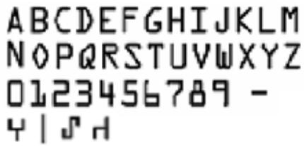 OCR-B (Support for %, /, and & characters can be implemented by the driver) OCR-B (Support for %, /, and & characters can be implemented by the driver)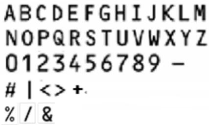 |
| Supported bar code font | UPC-A, UPC-E, JAN13/EAN13, JAN8/EAN8, CODE39, ITF, CODE128 | |
| Interface | USB ("USB Interface Specifications" on page 81) | |
Electrical Specifications
| Power supply | Model number | Epson specified adapter PS-180 |
| Input | 100 to 240 VAC 50 to 60 Hz 1.3 A | |
| Output | 24 VDC 2.1 A | |
| AC power consumption (100 to 230 V/50 to 60 Hz)* | Operating | Approximately 51.3 W |
| Standby | Approximately 5.9 W |
*: Average power under Epson operation conditions. Values will vary according to usage conditions and model.
Ink Cartridge
| Model number | SJIC18(K) |
| Color | Black |

Read the precautions on handling carefully before installing the ink cartridges.
( Cautions on Ink Cartridges (page 9))
Genuine Ink Cartridges Recommended
- For the best performance of the printer, it is recommended to use genuine Epson ink cartridges. Use of non-genuine Epson ink cartridges can adversely affect the printer and print quality and prevent the printer from realizing its maximum performance. Epson cannot guarantee the quality and reliability of non-genuine Epson products. Repairs for any damage or breakdown of this product due to the use of non-genuine Epson products will not be free of charge even if the warranty period is still valid.
- Color adjustment of the product is based on the use of genuine Epson ink cartridges. Use of non-genuine ink cartridges may result in reduced print quality. Epson recommends the use of genuine Epson ink cartridges.
Disposal of Ink Cartridges
When discarding ink cartridges, do so in accordance with the local laws, regulations, and rules of your country or geographic location.
USB Interface Specifications
USB (Type-B)

CAUTION
Be sure to use a power source that meets the following specifications for USB type B connector.
Rated 5 V DC / Class2 or Limited Power Source.
| General specification | USB 2.0 | |
| Communication speed | Hi-Speed (480 Mbps)Full-Speed (12 Mbps) | |
| Communication method | USB bulk transmissionUSB interrupt transmission | |
| Power supply specification | USB self power supply function | |
| Current consumed by USB bus | Not equipped with USB-HUB and MSR: | 0 mA |
| Equipped with USB-HUB and MSR: | 100 mA max(Not including the consumption current of devices connected to the USB-HUB) | |
USB (Type-A)
NOTE
USB (Type-A) is not equipped with some models.
| General specification | USB 2.0 |
| Communication speed | Hi-Speed (480 Mbps)Full-Speed (12 Mbps)Low-Speed (1.5 Mbps) |
| Communication method | USB bulk transmissionUSB interrupt transmission |
| Power supply specification | Bus Powered |
| Supply current*1 | 100 mA or less per port |
*1: This is a bus-powered hub and therefore cannot be directly connected to a bus-powered device with high power consumption or a bus-powered hub.
Printing Specifications
| Printing method | Line ink jet | |
| Nozzle arrangement | 360 nozzles in 2 lines | |
| Printing color | Black | |
| Dot density | 180×180 dpi | |
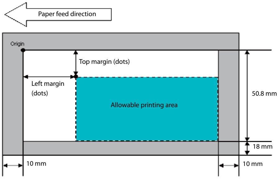
| Print height | 50.8 mm | |
| Print width | 80 to 215 mm (Depends on the paper length) | |
| Printable lines^*1 | Font A | 12 lines maximum |
| Font B | 16 lines maximum | |
| Characters per line^*1 | Font A | 59 to 126 |
| Font B | 78 to 169 | |
| Character spacing^*1 | Font A | 0.28 mm (2 dots) |
| Font B | 0.28 mm (2 dots) | |
| Line spacing^*1 | 4.23 mm | |
| Print speed^*2 | Approx. 1000 mm/s, approx. 600 mm/s, approx. 400 mm/s, approx. 240 mm/s | |
dpi: dots per 25.4 mm (dots per inch)
*1: Command configurable
*2: Depends on the type of image being acquired
Character Specifications
| Fonts | Alphanumeric charac- ters | 95 characters |
| Extended graphics | 128 characters × 11 pages (including user-defined page) | |
| International charac- ters set | 16 sets | |
| Character structure | Font A | 12 × 24 (including 2-dot horizontal spacing) |
| Font B | 9 × 17 (including 2-dot horizontal spacing) | |
| Character size*1(W × H) | Font A | Standard: 1.41 × 3.39 mmDouble-height: 1.41 × 6.77 mmDouble-width: 2.82 × 3.39 mmDouble-width/double-height: 2.82 × 6.77 mm |
| Font B | Standard: 0.99 × 2.40 mmDouble-height: 0.99 × 4.80 mmDouble-width: 1.98 × 2.40 mmDouble-width/double-height: 1.98 × 4.80 mm | |
| Characters per line | Font A | Standard: 42Double-height: 42Double-width: 21Double-width/double-height: 21 |
| Font B | Standard: 56Double-height: 56Double-width: 28Double-width/double-height: 28 |
*1: Space between characters is not included.
Characters can be scaled up to 64 times as large as the standard sizes.
When using Font B with a font style such as emphasized, some words may be hard to read. Check the font style in advance when using Font B.
Scanner Specifications
| Reading system | Contact image sensor (CIS) | |
| Resolution (H × W) | Cut sheet | 300 × 300 dpi, 240 × 240 dpi, 200 × 200 dpi,120 × 120 dpi, 100 × 100 dpi |
| ID cards | 600 × 600 dpi, 300 × 300 dpi, 200 × 200 dpi | |
| Gradation | Binary (Black and White)*1256-level (Grayscale)24-bit colorBinary and 256-level grayscale using IR (infrared ray) | |
| Data compression format | Binary (Black and White) | CCITT/group4 |
| 256-level (Grayscale) | JPEG | |
| Data format | Binary (Black and White)*2 | TIFF*3, BMP |
| 256-level (Grayscale) | TIFF, JPEG, BMP, Raster | |
| 24-bit color | TIFF, JPEG, BMP | |
| IR (infrared ray) | Binary (Black and White): TIFF BMP256-level Grayscale TIFF, JPEG, BMP, Raster | |
| Image size (H × W)*4 | Max. 109.728 mm × Max. 255 mm | |
| Image quality | In accordance with the Image Quality Assurance (IQA) standards formulated by the Financial Services Technology Consortium (FSTC) | |
| Deskewing images | Image skew is corrected in accordance with driver settings | |
| Auto size adjustment | The image is cropped in accordance with driver settings. | |
| Scanning speed | Cut sheet | Approx. 1000 mm/s, approx. 600 mm/s, approx. 400 mm/s,approx. 240 mm/s (depends on the image to read) |
| ID card | Approx. 118 mm/s, approx. 88 mm/s (depends on the image to read) | |
| Media specifications | Cut sheet | “Cut Sheet” on page 88 |
| ID card | “ID Card” on page 89 | |
dpi: dots per 25.4 mm (dots per inch)
*1: Cut sheets only
*2: When the driver binarizes a 256-level image, the check background pattern is automatically removed
*3: The 200 dpi resolution, binary, CCITT (Group 4) compressed TIFF format is based on the ANSI X9.100-181-2007 standard
*4: When the driver Auto Size function is used, the cut sheet size is virtually the same size.
The acquirable image cut sheet size is 107.358 mm × 235 mm maximum. ( 5 “Scanner Scan Area” on page 88)
MSR (Magnetic Stripe Reader) Specifications
NOTE
Some models are not equipped with a magnetic stripe card reader (MSR).
| Recognition method | Two-frequency coherent phase (F2F) | |
| Supported magnetic format | ISO 7811-6, AAMVANote: Including AAMVA standard California driver's licenses | |
| Supported card specifications | Reading medium | ISO/IEC7810 standard |
| Size (H × W) | 53.92 to 54.18 mm × 85.47 to 85.90 mm | |
| Thickness | 0.76± 0.08 mm | |
| Curvature | 1.5 mm | |
| Recognition rate | 99.5% or more | |
Paper Specifications
| Paper type | Check paper (compliant with ANSI standard), plain paper (only one sheet can be used) |
| Size (H × W) | 60 to 120 mm × 100 to 235 mm |
| Paper thickness | 0.075 to 0.2 mm |
| Paper weight | 60 to 120 g/m2 |
CAUTION
- Use of check paper, OCR paper, or other fine paper is recommended. Use of some paper types may result in double-feeding by the ASF or other paper feeding problems. It can also lower the capacity of the pocket.
- Use flat paper that is not curled or bent (especially the leading edge), curved, wrinkled, or other problems. Paper that is not flat can jam.
- Do not insert paper that has clips, staples, or any foreign objects affixed. Doing so can cause paper jams, MICR reading problems, damage to the MICR head or scanner head, and other problems.
- Since the paper sensor is a reflective sensor, do not use paper that has holes, that is transparency, or that has any areas with reflectance less than 40% in the position shown in the illustration below.
However, fanfold paper guide holes with a diameter of 6 mm or less are not detected by the sensor.
Area where holes are not allowed and paper reflectance is no less than 40%
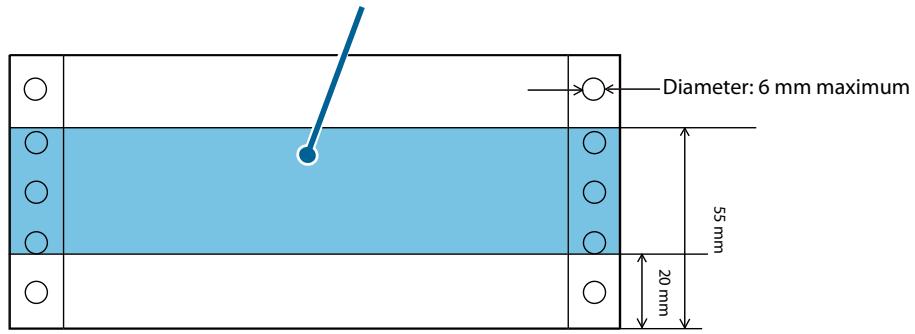
Printable Area
- When the print start position is based on the leading edge of the paper
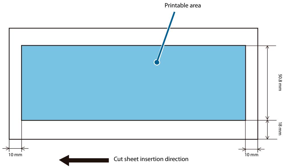
- When the print start position is based on the trailing edge of the paper
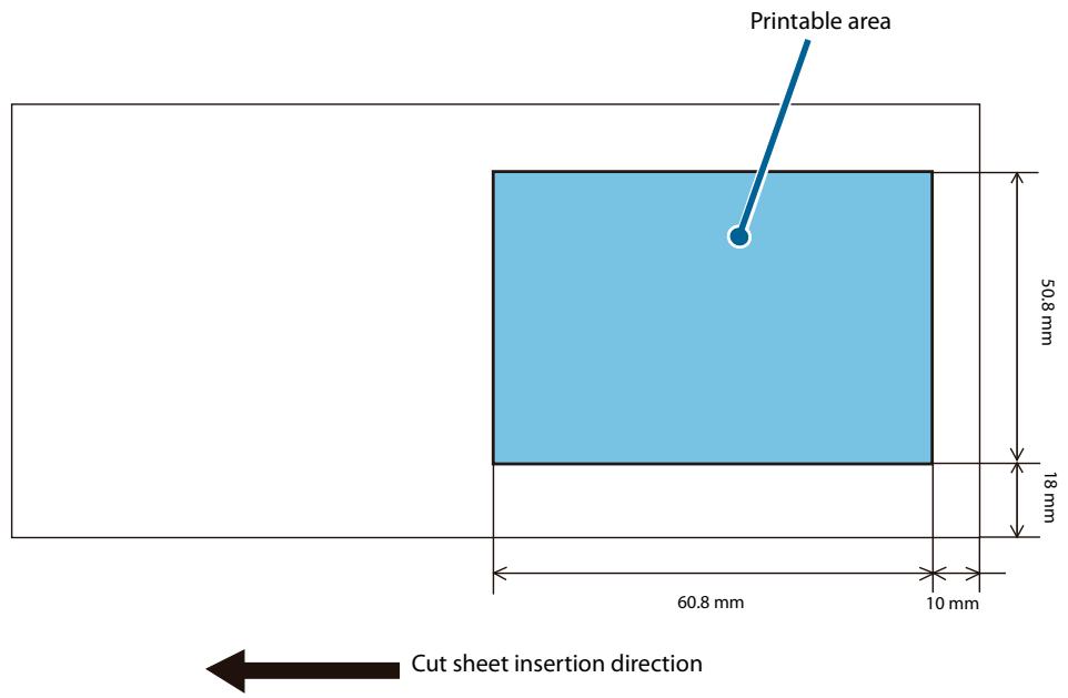
CAUTION
The area that starts 30 mm from the end of the paper is printable, but the printing may be disordered.
Scanner Scan Area
Cut Sheet
The a and b areas in the illustration below may not be readable. The quality of the scanned image may be lower in the c area.
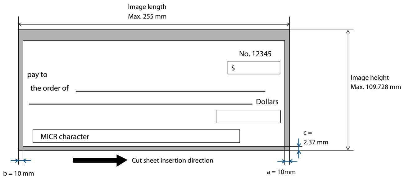
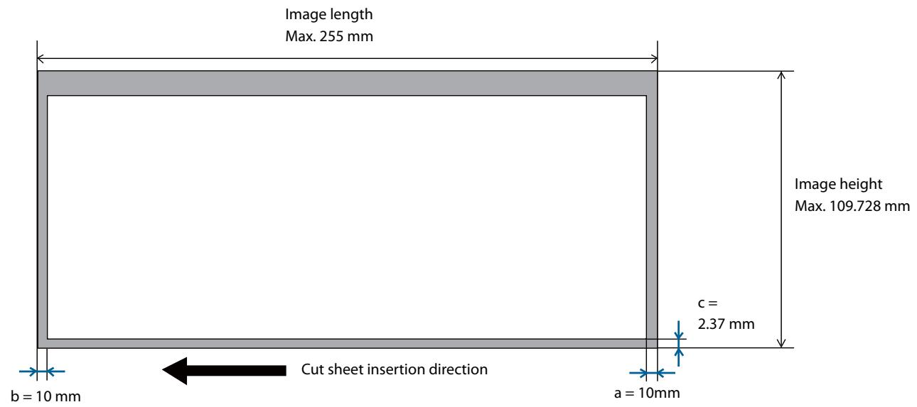
ID Card
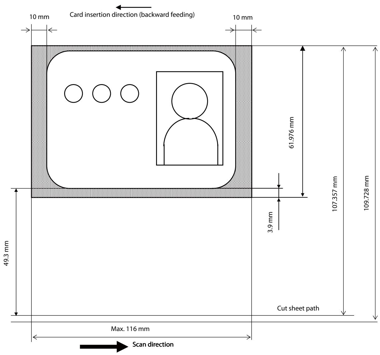
MICR Reading Area
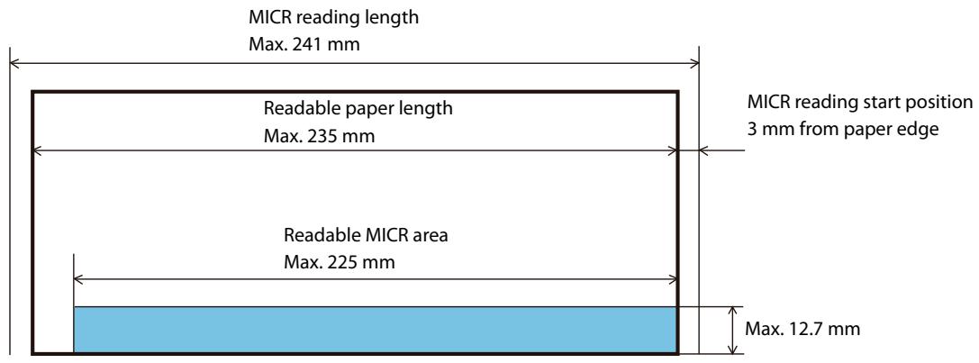
other
| Metric | Value | | --- | --- | | MICR reading length | Max. 241 mm | | Readable paper length | Max. 235 mm | | Readable MICR area | Max. 225 mm | | MICR reading start position | 3 mm from paper edge | | Readable MICR area | Max. 12.7 mm |
Card insertion direction (backward feeding)
Electronic Endorsement Area
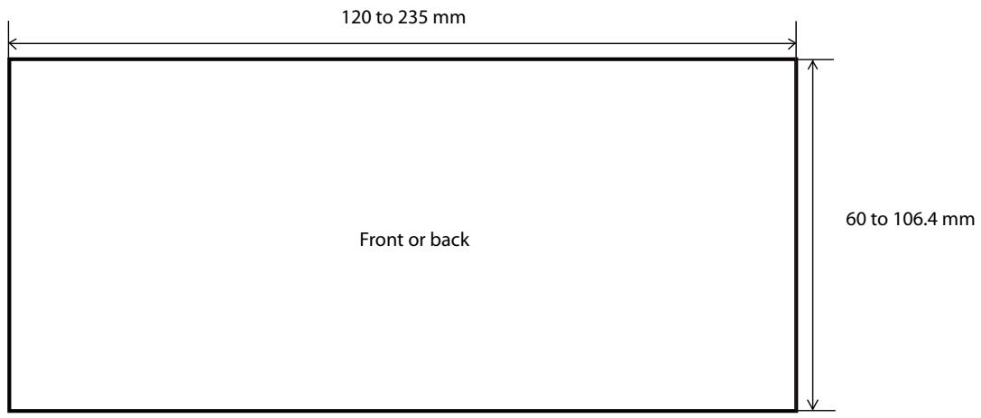
Environmental Specifications
| Temperature/humidity | Operating | 10 to 35°C, 20 to 80%RH, no condensation (Refer to the operating environment range in the illustration below) |
| Storage | Ink not charged: -20 to 60°C, 5 to 85%RH (no condensation)Within 120 H at -20°C or 60°CInk charged: -20 to 40°C, 20 to 85%RHWithin 120 H at -20°CWithin 6 months at 0 to 30°CWithin 1 month at 40°C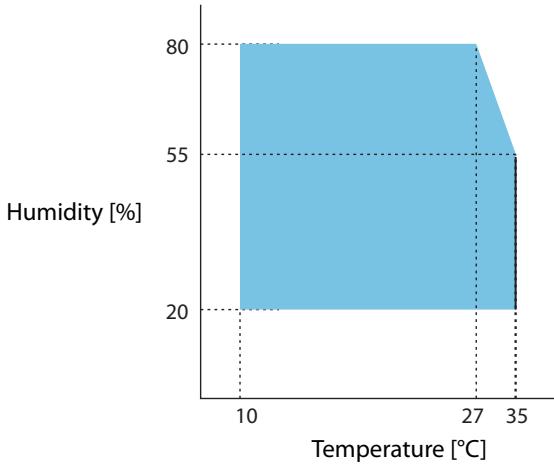 | |
| Pressure(elevation) | 700 to 1050 hPa (approx. 0 to 2000 m above sea level) | |
| Noise | Approx. 63 dB (ANSI Bystander position)Note: The above noise level values are based on Epson evaluation conditions.Sound values are affected by the paper being used, print contents, and setting values (print speed, print density). | |
Reliability
| Life | Printer mechanism | 2 million sheets (Including check and card reading, with cleaning every 100 thousand sheets.) |
| ASF | 2 million sheets | |
| Ink jet head | 6 billion shots/nozzle | |
| MTBF | 180,000 hours | |
| MCBF | 4.94 million processes | |
Overall Dimensions
One-pocket Model
Height: 206 mm
Width: 142 mm
Depth: Pocket pulled out: 374.8 mm
Pocket stowed: 263.8 mm
Weight: Approx. 3.7 kg
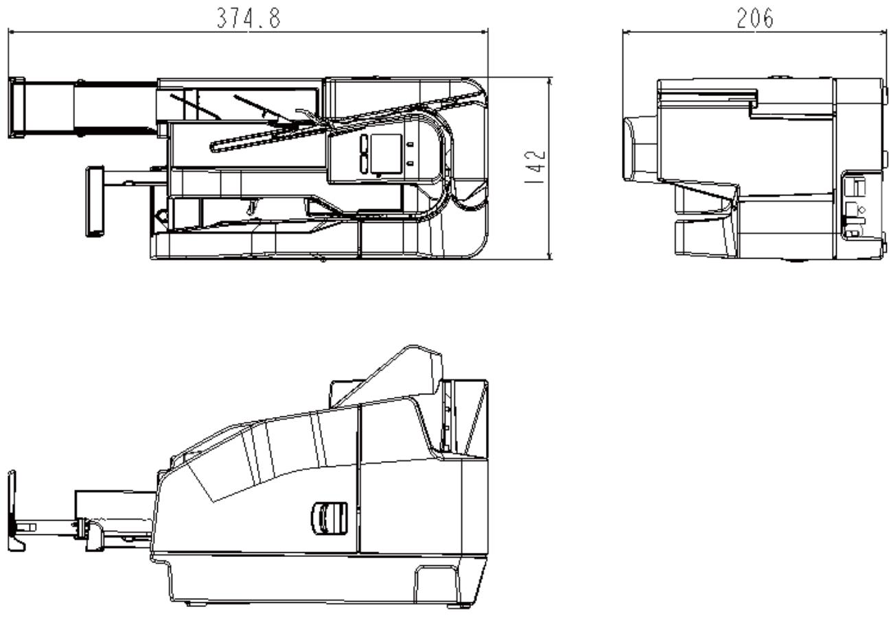
[Unit: mm]
Two-pocket Model
Height: 206 mm
Width: 167 mm
Depth: Pocket pulled out: 409.8 mm
Pocket stowed: 298.8 mm
Weight: Approx. 4.1 kg
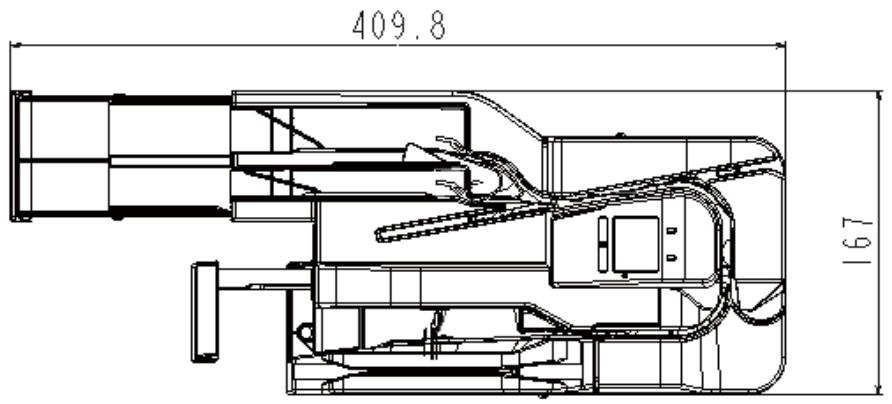
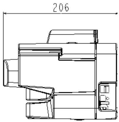
natural_image
Technical line drawing of a mechanical device with no visible text or symbols[Unit: mm]
Character Code Tables
For information on character codes, access the URL below and refer to the “Character Code Tables for TM printers”.
http://www.epson-biz.com/pos/reference/charcode/
- Safety Precautions
- Product Overview
- Setup
- Advanced Product Use
- Application Development Information
- Handling the Product
- Troubleshooting
- Product Specifications
- Notes
- Copyrights
- Table of Contents
- ■ Safety Precautions....7
- ■ Restriction of Use 10
- ■ About This Manual.... 11
- Product Overview 13
- ■ Features .... 13
- ■ Product Configuration .... 14
- ■ Part Names and Functions .... 15
- ■ Checking the Product Status 19
- ■ Cut Sheet Processing Modes.... 24
- ■ NV Memory 33
- Setup 35
- ■ Setup Flow.... 35
- ■ Product Installation 36
- Advanced Product Use.... 45
- Application Development Information 51
- Handling the Product 57
- Troubleshooting....71
- Product Specifications....79
- Meanings of Symbols
- WARNING
- CAUTION
- NOTE
- Cautions on Installation
- Cautions on Power Supply
- Cautions on Ink Cartridges
- Restriction of Use
- About This Manual
- Purpose of This Manual
- Manual Organization
- Manual Illustrations
- Features
- Product Configuration
- Accessories
- Part Names and Functions
- Front
- Operation Panel
- Rear
- Checking the Product Status
- Replacement Timing of Consumables
- Statuses and Errors
- Cut Sheet Processing Modes
- High-speed Mode
- Document Processing Sequence
- Confirmation Mode
- With overlap
- When back feeding is required with 2-pocket models
- Without overlap
- When back feeding is not necessary with 1-pocket models/2-pocket models
- Speed of Each Processing Mode
- Processing Speed Conditions
- Processing Modes
- NV Memory
- NV Graphics Memory
- NV User Memory
- Memory Switch
- User-defined Page
- Maintenance Counters
- Setup Flow
- Product Installation
- Removing the Packing Materials
- Installation
- Location Appropriate for Installation
- Connecting to a Host Computer
- Connecting a Power Supply
- Installing the Ink Cartridges
- Gently press the ink cartridge into the product.
- Close the ink cartridge cover.
- Adjusting LCD Backlight Brightness
- Test Printing
- Software Settings
- Function
- Transmits the power ON information
- Auto line feed
- Remote wake-up
- Sets time to check ink head cleaning
- Validation settings
- Cut sheet settings
- Time to enter power saving mode
- Function to prevent printing on the back side of documents (endorse) without magnetic ink characters
- Setting/Confirmation Mode
- Self-test Mode
- NV Graphics Information Print Mode
- Operating Environment
- DPM Model
- DPM Model
- Driver
- For Windows Environment
- List of Supported Functions
- For Linux Environment
- Utilities
- TM-S2000II Utility
- Epson Deployment Tool
- Downloading Software
- Turning On/Off
- Turning the Power On
- Turning the Power Off
- Opening a Cover
- Opening the Ink Cartridge Cover
- Opening the MICR Cover or Scanner Cover
- Replacing the Ink Cartridges
- Cut Sheet Processing
- Process Flow
- Loading Cut Sheets
- Pull out the ASF guide and pocket guide to match the length of the paper.
- Load the cut sheets so they are aligned with the ▲ mark on the top of the ink cartridge cover.
- Load the paper and remove your hand.
- Removing Cut Sheets
- ID Card Processing
- Insert the ID card into the slot and slide it.
- Magnetic Stripe Card Processing
- Cleaning the Product
- Cleaning the Exterior
- Ink Head Cleaning
- Cleaning the Paper Feeding Path
- Cleaning kit model numbers
- Cleaning Using the Application
- Cleaning Using the Printer
- Cleaning the Scanner
- Preparing for Transport
- The Product Does Not Turn On
- Lit or Flashing ! (ERROR) LED
- Error Message Displayed on the LCD
- Recoverable Error
- Unrecoverable Error
- Cut Sheet Jam
- ID Card Does Not Come Out
- Problems with Print Quality
- Problems with Reading Quality
- Cannot Read Magnetic Ink Characters Correctly
- Poor Cut Sheet or ID Card Reading Quality
- Electrical Specifications
- Ink Cartridge
- Genuine Ink Cartridges Recommended
- Disposal of Ink Cartridges
- USB Interface Specifications
- USB (Type-B)
- USB (Type-A)
- MSR (Magnetic Stripe Reader) Specifications
- Paper Specifications
- Printable Area
- Scanner Scan Area
- Cut Sheet
- ID Card
- Overall Dimensions
- One-pocket Model
- Two-pocket Model
- Character Code Tables
Brand : EPSON
Model : TM-S2000II
Category : Multifunction Printer