
SPREADING WINGS S1000+ ARF - SPREADING WINGS S900 RTF - Professional drone DJI - Free user manual and instructions
Find the device manual for free SPREADING WINGS S1000+ ARF - SPREADING WINGS S900 RTF DJI in PDF.
| Brand | DJI |
| Model | Spreading Wings S1000+ ARF / S900 RTF |
| Product type | Professional drone for aerial photography and cinematography |
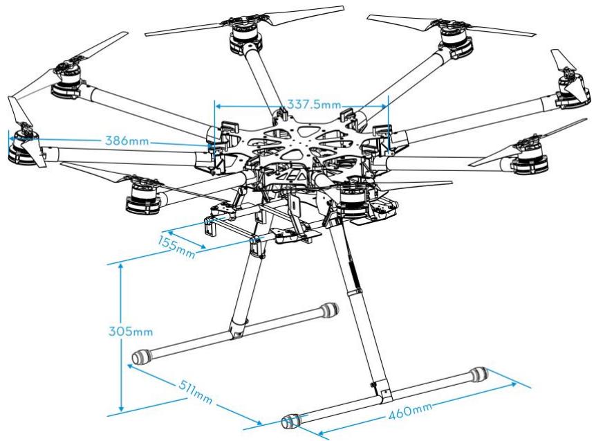
| Diagonal wheelbase | 1045 mm |
| Arm length | 386 mm |
| Center diameter | 337.5 mm |
| Landing gear dimensions | 460 x 511 x 305 mm (upper width 155 mm) |
| Total weight (without battery) | 4.2 kg |
| Max takeoff weight | 11.0 kg |
| Min takeoff weight | 6.0 kg |
| Power supply | LiPo 6S battery, 10000-20000 mAh, 15C min |
| Max power consumption | 4000 W |
| Hovering power consumption | 1500 W (for 9.5 kg) |
| Hovering flight time | 15 min (with 15000 mAh battery and 9.5 kg) |
| Motors | 4114, kV400, max power 500 W |
| ESC | 40 A, 6S, signal frequency 30-450 Hz |
| Propellers | 15 x 5.2 inches, foldable, weight 13 g |
| Main features | Retractable landing gear, vibration dampeners, 360° panoramic view, integrated power hub, patented coaxial connectors, compatible with DJI A2 and WK-M flight systems |
| Maintenance and cleaning | Check the condition of dampeners and propellers before each flight, clean with a dry cloth, do not use liquids |
| Safety | Do not fly in rain or snow, keep a safe distance, use 6S LiPo batteries, check connections |
| Operating temperature | -10 °C to +40 °C |
| Spare parts and repairability | Complete list of parts available in the manual, many spare parts (arms, motors, ESC, etc.) |
Frequently Asked Questions - SPREADING WINGS S1000+ ARF - SPREADING WINGS S900 RTF DJI
User questions about SPREADING WINGS S1000+ ARF - SPREADING WINGS S900 RTF DJI
0 question about this device. Answer the ones you know or ask your own.
Ask a new question about this device
Download the instructions for your Professional drone in PDF format for free! Find your manual SPREADING WINGS S1000+ ARF - SPREADING WINGS S900 RTF - DJI and take your electronic device back in hand. On this page are published all the documents necessary for the use of your device. SPREADING WINGS S1000+ ARF - SPREADING WINGS S900 RTF by DJI.
USER MANUAL SPREADING WINGS S1000+ ARF - SPREADING WINGS S900 RTF DJI
Spreading Wings S1000 User Manual
V 1.10
2014.11
www.dji.com
Disclaimer
Thank you for purchasing this DJI product. Please visit the S1000 page on www.dji.com regularly to keep up with product information, technical updates and manual corrections. Information in this manual is subject to change without notice in line with product upgrades and updates.
In using this product, you hereby agree to this disclaimer and signify that you have understood all points completely. When assembling this product, follow all instructions carefully. The manufacturer and seller assume no liability for any damage or injury arising from the use of this product.
DJI is a registered trademark of DJI Innovations. Names of product, brand, etc., appearing in this manual are trademarks or registered trademarks of their respective owner companies. This product and manual are copyrighted by DJI Innovations with all rights reserved. No part of this product or manual shall be reproduced in any form without the prior written consent or authorization of DJI Innovations. No patent liability is assumed with respect to the use of the product or information contained herein.
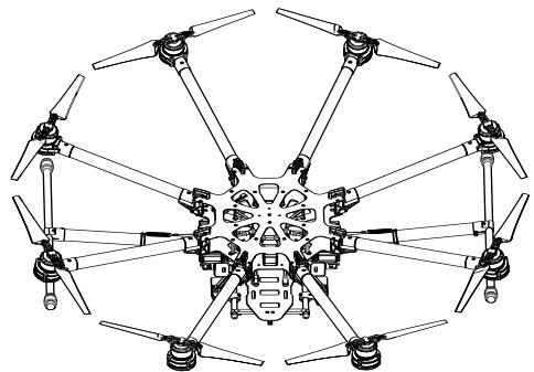
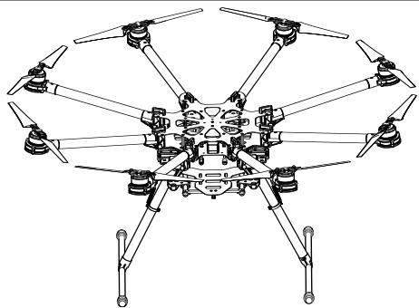
About
The S1000 is designed for professional aerial photography and cinematography. It is user friendly, safe, stabilized and easy to fly while its integrated design makes assembly and configuration simple and fast. Retractable landing gear, vibration dampers, small frame arm incline and minimized gimbal mount allows for a clear 360 degree view from the camera. An integrated power hub with patented coaxial connectors, built-in high-speed ESCs and motors with high efficiency propellers ensure dynamic stability and maximized power efficiency. Used with a professional DJI multi-rotor autopilot system, the S1000 can hover and fly reliably making it ideal for photography and cinematography.
Contents
Disclaimer. 2
About 3
Contents 4
Caution 5
In The Box. 6
Tools Required 6
Mounting Landing Gear 7
Mounting Frame Arms 8
Mounting Electronics and Wiring 11
Connecting XT60 Ports on Center Frame. 17
17
Setting Landing Gear 19
Mounting the Gimbal 21
Appendix 23
ESCSound 23
ESCLED 23
Specifications 23
Gain Value Settings (with the A2 flight control) 24
FAQ. 25
Soldering the ESC. 25
Remounting the Propeller 25
Propeller Precautions 25
Using Propeller Holder. 26
Assembling Motor Vibration Absorbers 26
Remounting Landing Gear Servo 27
Recalibrating Servo Travel 27
Part List. 29
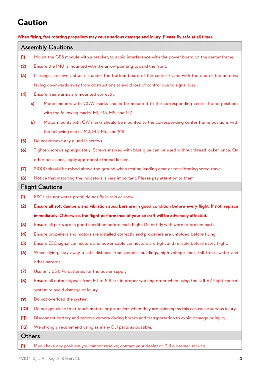
Caution
When flying, fast rotating propellers may cause serious damage and injury. Please fly safe at all times.
Assembly Cautions
Mount the GPS module with a bracket, to avoid interference with the power board on the center frame.
(2) Ensure the IMU is mounted with the arrow pointing toward the front.
(3) If using a receiver, attach it under the bottom board of the center frame with the end of the antenna facing downwards away from obstructions to avoid loss of control due to signal loss.
(4) Ensure frame arms are mounted correctly.
a) Motor mounts with CCW marks should be mounted to the corresponding center frame positions with the following marks: M1, M3, M5, and M7.
b) Motor mounts with CW marks should be mounted to the corresponding center frame positions with the following marks: M2, M4, M6, and M8.
(5) Do not remove any glued-in screws.
(6) Tighten screws appropriately. Screws marked with blue glue can be used without thread locker once. On other occasions, apply appropriate thread locker.
(7) S1000 should be raised above the ground when testing landing gear or recalibrating servo travel.
(8) Notice that matching the indicators is very important. Please pay attention to them.
Flight Cautions
(1) ESCs are not water-proof, do not fly in rain or snow.
(2) Ensure all soft dampers and vibration absorbers are in good condition before every flight. If not, replace immediately. Otherwise, the flight performance of your aircraft will be adversely affected.
(3) Ensure all parts are in good condition before each flight. Do not fly with worn or broken parts.
(4) Ensure propellers and motors are installed correctly and propellers are unfolded before flying.
(5) Ensure ESC signal connectors and power cable connectors are tight and reliable before every flight.
(6) When flying, stay away a safe distance from people, buildings, high-voltage lines, tall trees, water and other hazards.
(7) Use only 6S LiPo batteries for the power supply.
(8) Ensure all output signals from M1 to M8 are in proper working order when using the DJI A2 flight control system to avoid damage or injury.
(9) Do not overload the system.
(10) Do not get close to or touch motors or propellers when they are spinning as this can cause serious injury.
(11) Disconnect battery and remove camera during breaks and transportation to avoid damage or injury.
(12) We strongly recommend using as many DJI parts as possible.
Others
If you have any problem you cannot resolve, contact your dealer or DJI customer service.
In The Box
| Center Frame×1 | Frame Arm×8 |
| Landing Skid Tube×2(with Silicone Rubber Damper) | Landing Gear Leg×2 |
| GPS Collapsible Mount×1 | Spring×2 |
| Connector Set×1 | 3-PIN Servo Cable×1 |
| Screw Package×1 | Accessories package×1 |
| For frame arms mount: M4x35For landing gear mount: M3x8, M2.5x6.7 | Heat-shrinkable tube (diameter of 10mm) |
Tools Required
| Tools | Usage |
| 2.0mm Hex Wrench, 2.5mm Hex Wrench | Mounting screws. |
| Thread Locker | Fastening screws. |
| Nylon Cable Tie | Binding devices and wires. |
| Scissors | |
| Cutting Pliers/Dykes | |
| Foam Double Sided Adhesive Tape | Mounting receiver, controller and other modules. |
| Hot Air Gun | Fixing power cable connectors. |
Mounting Landing Gear
Instructions
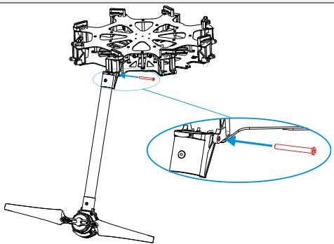
- Slide landing gear leg into landing skid tube then affix the joints with M2.5x6.7 screws. Ensure silicone rubber dampers are attached.
- Insert the landing gear leg into connection point on the center frame. Affix in place with M3x8 screws.
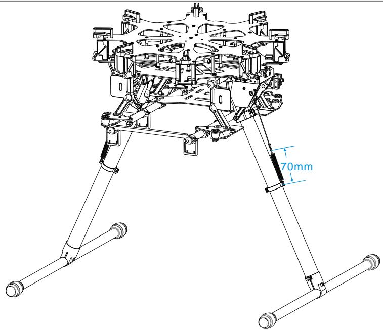
- Connect springs to both parts to ensure safety.
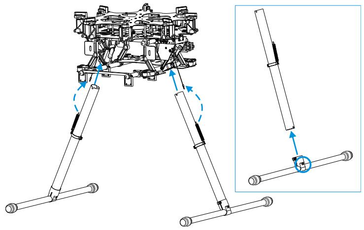
- Complete. Spring length is 58.5mm unstretched and 70mm stretched.
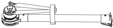
Mounting Frame Arms
Instructions
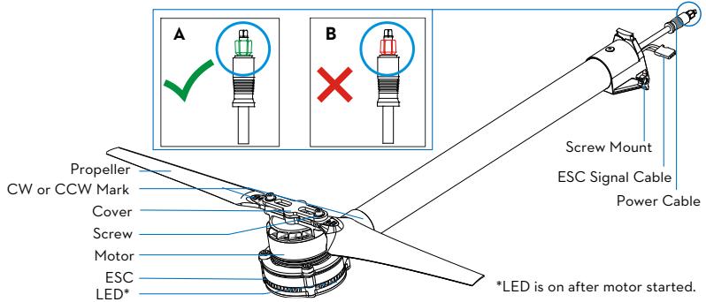
- Check arms.
(1) Check propellers for cracks, then install and screw propeller cover on tightly.
(2) Ensure motors are mounted firmly and rotate freely.
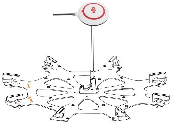
(3) Mount arms with red propeller covers to M1 and M2 to indicate the nose of the S1000.
(4) Distinguish marks CW and CCW on the arms. Mount the arms with mark CCW to the M1, M3, M5, and M7 positions of the center frame. The arms marked CW should be mounted to the M2, M4, M6, and M8 positions of the center frame.
(5) Check power cable connector. Diagram A shows normal and B shows abnormal. The correct connection method is detailed below.
i. Remove shrapnel from the damaged connector as demonstrated by diagram A using tweezers or a knife. ii. Replace the power cable connector if the shrapnel damage is too great (e.g. connector is broken or bent and cannot be pulled out or plugged in.
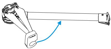
- Insert frame arm vertically into the mounting area on the center frame.
- Adjust screw mounts of frame arm and center frame.
- Insert the M4x35 screw from the right of the frame arm as the thread is located on the left of the screw mount. Tighten screw appropriately. Over tightening may lead to connector abrasion.
- Gently lift frame arm.
- Twist knob to lock in place. Be sure there is an audible click sound to ensure a proper lock. Check the arm for movement. To store, untwist the knob and lower frame arm.
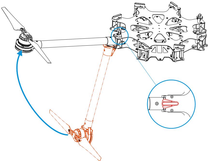
- Plug ESC signal cable into center frame.
- Plug power cable into center frame. Heat-shrinkable tubes can be used to stop the connector from coming off.

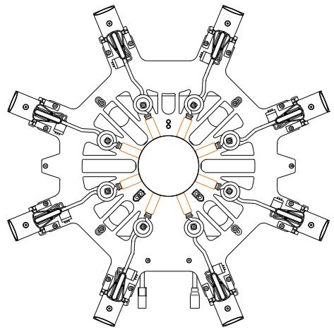
- Ensure all ESC signal cables (red) and power cables (blue) are connected to the center frame correctly. Power cables can be fixed to center frame pillars to tidy them away. Make sure to use heat-shrinkable tubes correctly (orange).
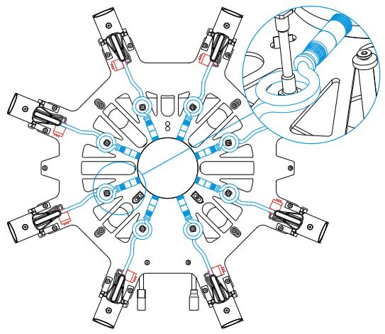
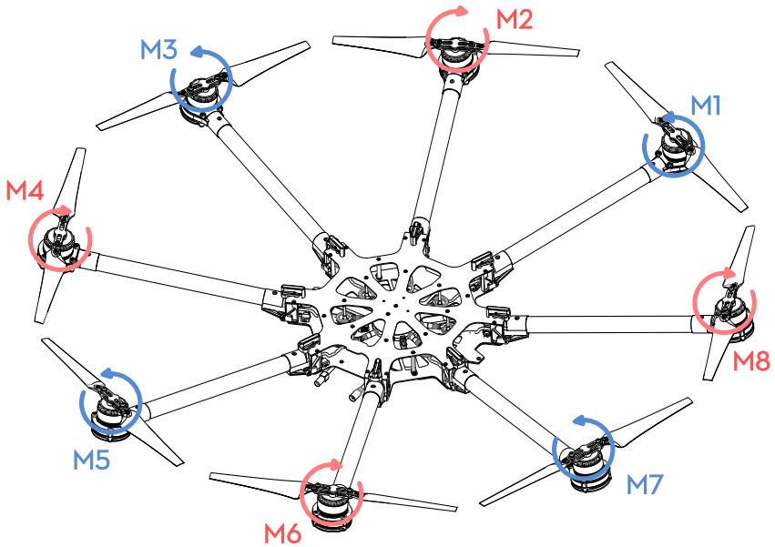
- Double check all frame arms. Arms M1 and M2 are the forward facing (nose), arms M5 and M6 are the tail. Seen from the top, motors on arms M1, M3, M5 and M7 rotate counter clockwise while those on arms M2, M4, M6 and M8 rotate clockwise.
Mounting Electronics and Wiring
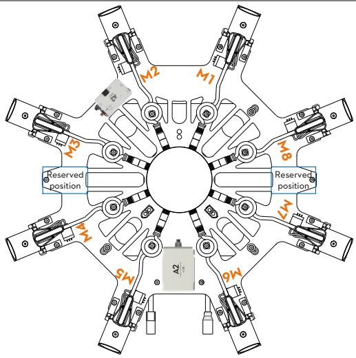
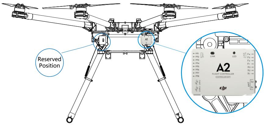
Eight positions are reserved for mounting a flight control system, wireless video transmission module, receiver, and other items. The DJI A2 flight control system has been used here as an example. If using an A2, follow mounting and wiring instructions found in the A2 flight control system user manual. If using the DJI WK-M flight control system, please refer to the WK-M user manual for connections. Also be sure your firmware on your DJI flight controller has been updated to the latest version.
Instructions
- Attach IMU module to the IMU area of the center frame. Ensure that it points toward the nose and does not touch any other components as vibration can cause it to malfunction.
- Attach the PMU module to the center frame.
- Mount the main controller in the reserved position near the PMU module.
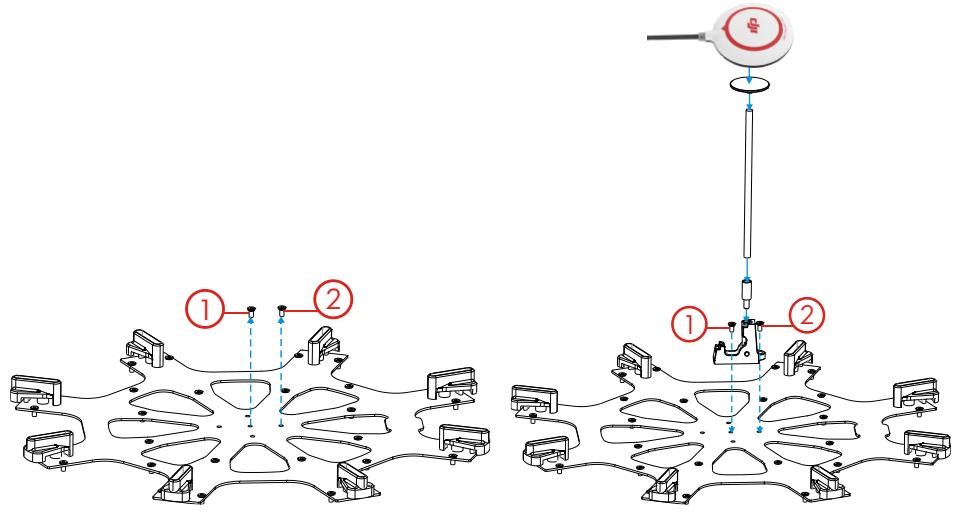
- Attach the GPS collapsible mount to the center frame using M2.5x6.7 screws. Washer for GPS collapsible mount is pre-installed on the center frame. To install GPS collapsible mount, remove the screw from the washer then follow the below instructions:
(1) Remove screw ① from the center frame.
(2) Position GPS collapsible mount then return the screw to its original position and tighten.
(3) Remove remaining screw ② from center frame.
(4) Position GPS collapsible mount then return screw to its original position and tighten.
- Mount a GPS module to the GPS mount with a bracket. Ensure the arrow points toward the nose and avoid catching fingers in the bracket when folding for transportation.
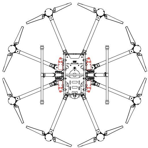
- The other reserved positions are indicated in the diagram below and can be used for mounting a receiver, LED flight indicator, iOSD module and wireless video transmission module.
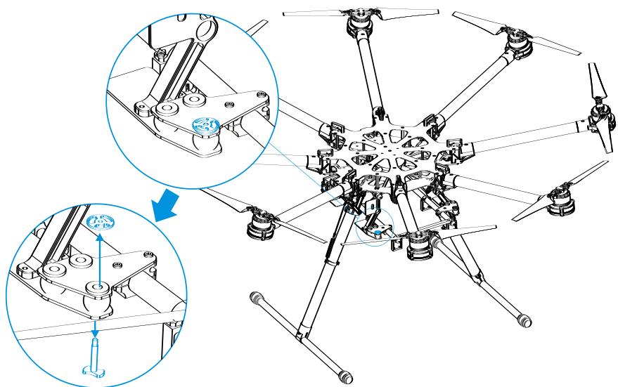
- Check that every anti-drop system has been firmly installed in the reserved positions. Thread locker is recommended.
(1) Remove anti-drop to add appropriate thread locker.
(2) Replace and tighten.
Notes
(1) Only mount the IMU in the IMU position of the center frame.
(2) Mount the GPS with a bracket to avoid interference from the center frame power board.
(3) Use glue to install the GPS bracket. Ensure it is firm and reliable before every flight.
(4) Always test motors using the Assistant Software after installation. Refer to the "Flight control system user manual" for details.
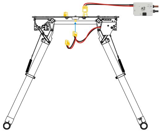
Connecting main controller to center frame
- Finish flight control system connection according to the A2 flight control system user manual.
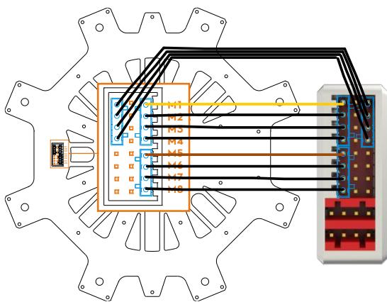
- Link connector set (blue) to ESC signal outlet on the center frame then link connector set (blue) to main controller as shown below.
(1) Yellow 4-pin cables are for M1~ M4 connections. Yellow cable should be connected to M1.
(2) Brown 4-pin cables are for M5~ M8 connections. Brown cable should be connected to M5.
(3) Black 4-pin cables are for four continuous ground pins connections. M1-M4 are connected as the following diagram shows.
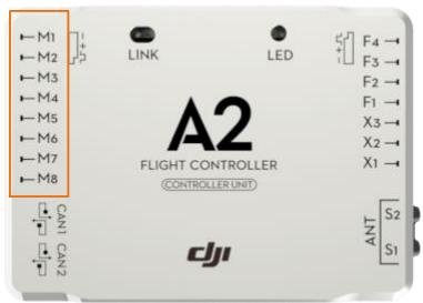
Notes
If using a DJI WK-M flight controller, you must use the wires that came with the WK-M. M1 through M6 correspond to each motor number. M7 corresponds to F1 and M8 corresponds to F2 on the WK-M.
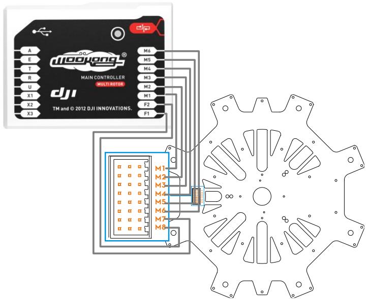
Connecting main controller and landing gear
- Connect left servo cable near M4 to the "RLG" port near M4 on the center frame, then ensure the "RLG" port near M3 is connected to the "L" port of the landing gear control board.
- Connect right servo cable near M7 to the "R" port of the landing gear control board using a servo cable.
- For the A2 flight control system, connect the F1 port of the main controller to "IN" port of the landing gear control board. Other flight control systems connect a 2-position channel receiver to the "IN" port.
Notes
(1) If right and left servo cables are reversed, landing gear will not be function.
(2) Wire neatly to avoid cables being damaged by frame edges.
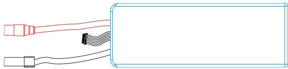
Connecting XT60 Ports on Center Frame
The bottom board is a power distribution board with three XT60 connectors for battery power.
Instructions
- Connect PMU power cable to XT60 connector on top of the bottom board.
- Connect landing gear control board cable to XT60 connector on the bottom of the bottom board.
- Other connectors can supply power for other DJI devices if required.
Installing Battery
Soldering battery connectors
AS150 anti spark connectors are used. They must be soldered to battery power cables.
- Remove original battery connector. Avoid cutting power and ground cables at the same time as this can cause a short circuit. We recommend wrapping unsoldered cable with insulating tape to prevent accidental connection.
- Pass the black ground wire through the black housing. After passing the wire through, solder the female bullet connector to the ground wire. Wait for the soldered connection to cool, then pull the housing back over the bullet connector.
- Screw and pass the red power wire through the red housing. After passing the wire through, solder the male bullet connector to the power wire. Wait for the soldered connection to cool, and then screw and pull the housing back over the bullet connector.
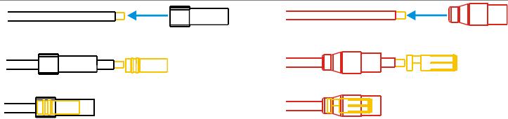
Connectors soldering diagram
Connectors are soldered
Installing and connecting battery
- Attach battery to battery tray. Do not use an oversized battery. Maximum installation dimension is 80mm X 120mm X 200mm.
- Insert black connector① then red connector② to power on. Pull out red connector② then black connector① to power off.

Setting Landing Gear
Using a 2-position R/C transmitter switch, landing gear retraction can be carried out remotely.
Setting up the transmitter
Select a 2-position switch (default setting is OK) as the control input for the landing gear. Ensure the corresponding receiver port is connected to the "IN" port on control board. For the A2 flight control system, connect the main controller's F1 port to "IN" port on control board.
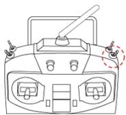

Raise: Toggle the switch to this position to raise the landing gear.

Lower: Toggle the switch to this position to lower the landing gear.
Notes:
(1) If the transmitter switch has a FailSafe function, set the FailSafe value to the [Lower] position. This ensures that landing gear will lower automatically when the receiver enters FailSafe mode.
(2) To avoid accidental switch triggering, slide levers or other controls can be used for landing gear control.
Usage procedures
- Ensure transmitter and receiver batteries are fully charged.
- Toggle switch to [Lower] position, and then turn on transmitter.
- Ensure [R], [L] and [IN] connections are correct.
- Ensure landing gear is in the [Lower] position then power on the system. If the green LED on the landing gear control board is solid, everything is normal. If it flashes green slowly, re-calibrate the system according to instructions in "Recalibrating Servo Travel".
- Toggle switch to [Raise] position ONLY AFTER takeoff.
- Toggle switch to [Lower] position for landing.
Tips
(1) Servo power will shut off within 3 seconds after the landing gear has reached its target position.
(2) When powering on the system, if the transmitter switch is in the [Raise] position, the LED will flash red quickly as a warning. Toggle the switch to the [Lower] position to continue.
(3) If there is an abnormal signal or no signal input into the [IN] port, the LED will slowly flash red. Check receiver and connections for problems.
(4) If servo power consumption is too high, the LED will light up red. If this lasts more than 4 seconds, landing gear will lower and the LED will flash green slowly. Re-calibration is needed before flying.
(5) A2 flight control system users can use the A2 Assistant Software to set intelligent gear on the "Advanced" page. Refer to the "A2 flight control system user manual" for details.
LED Control Board Indicator
| System normal | |
| Calibration required | |
| Recalibration required | |
| Calibration failed | |
| Enter calibration mode | |
| System calibrating | |
| Motor stalled | |
| Unsafe startup alert | |
| Input signal abnormal |
Specifications
| Parameter | Range | Parameter | Range |
| Working Voltage | 3S-6S (LiPo) | Input Signal | PWM (High-Pulse Width 800us-2200us) |
| Working Current | Max 1A@6S | Output Signal | PWM(Mid Position is 1520us) in 90Hz |
| Working Temperature | -20~70°C | Output Voltage | 6V |
| Total Weight | 875g | Servo Travel | 150° (Minimum120°) |
Mounting the Gimbal
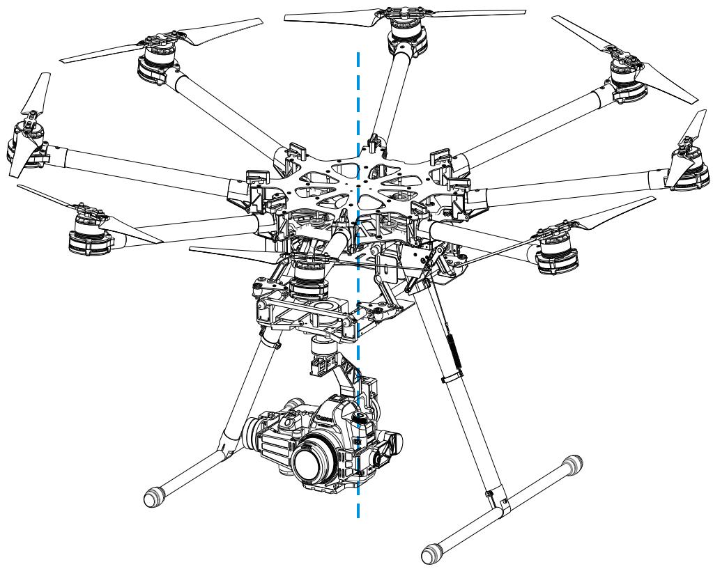
Before assembling the gimbal, install GCU as shown below. Be sure to install on the side as shown below. A DJI Z15-5D gimbal has been used as an example in the following diagrams.
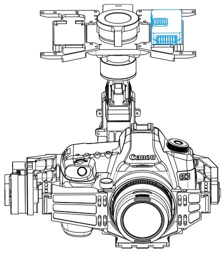
The connectors on gimbal should be removed for better performance, then the gimbal can be mounted to the lower connection points. A DJI Z15-5D gimbal has been used as an example in the following diagrams.
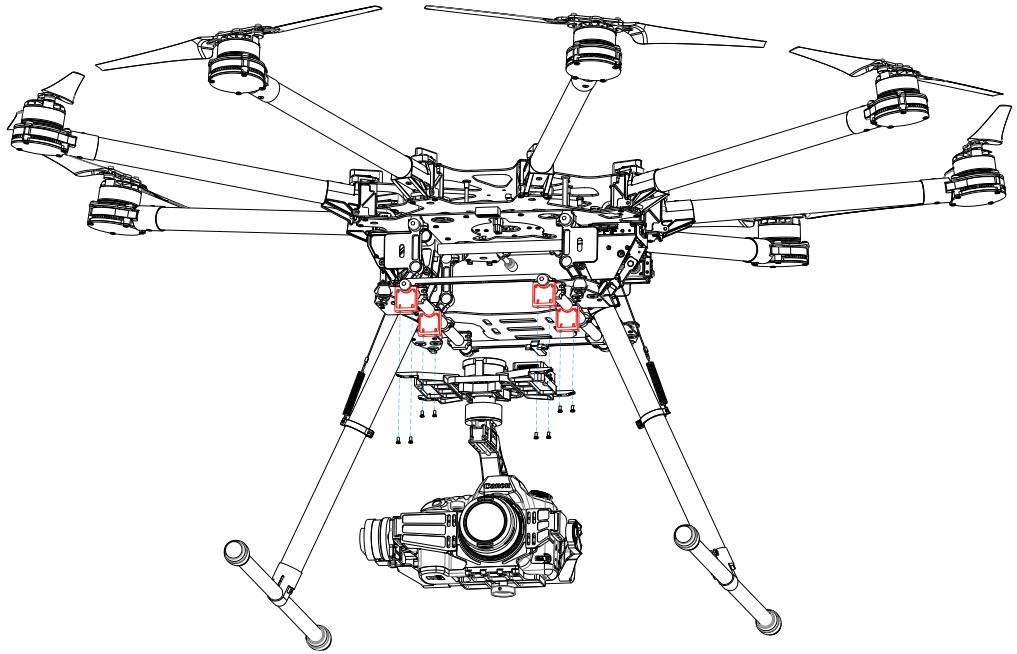
Check that the system's center of gravity is at the blue line as shown in the below diagram.
Appendix
ESC Sound
| ESC State | Sound |
| Ready | J1234567--B--B |
| Throttle stick is not at bottom | BAAAAAAAA... |
| Input signal abnormal | B--------B--------B... |
| Input voltage abnormal | BB--BB--BB--BB... |
ESC LED
| ESC State | LED |
| Standby | Off |
| Motor rotating | Solid Red or Green On |
| Motor rotating at full throttle position | Solid Yellow On |
Tips:
DJI ESCs are specially designed for multi-rotors. When used with DJI autopilot systems parameters and travel ranges do not have to be calibrated.
Specifications
| Frame | |
| Diagonal Wheelbase | 1045mm |
| Frame Arm Length | 386mm |
| Frame Arm Weight (with Motor, ESC, Propeller) | 325g |
| Center Frame Diameter | 337.5mm |
| Center Frame Weight (with Landing Gear Mounting Base, Servos) | 1330g |
| Landing Gear Size | 460mm(Length)×511mm(Width)×305mm(Height) (Top width: 155 mm) |
| Motor | |
| Stator Size | 41×14mm |
| kV | 400rpm/V |
| Max Power | 500W |
| Weight (with Cooling Fan) | 158g |
| ESC | |
| Working Current | 40A |
| Working Voltage | 6S LiPo |
| Signal Frequency | 30Hz ~ 450Hz |
| Drive PWM Frequency | 8KHz |
| Weight (with Radiators) | 35g |
| Foldable Propeller (1552/1552R) | |
| Material | High strength performance engineered plastics |
| Size | 15×5.2inch |
| Weight | 13g |
| Flight Parameters | |
| Takeoff Weight | 6.0Kg - 11.0Kg |
| Total Weight | 4.2Kg |
| Power Battery | LiPo (6S, 10000mAh-20000mAh, 15C(Min)) |
| Max Power Consumption | 4000W |
| Hovering Power Consumption | 1500W (@9.5Kg Takeoff Weight) |
| Hovering Time | 15min (@15000mAh& 9.5Kg Takeoff Weight) |
| Working Environment Temperature | -10 °C - +40 °C |
Gain Value Settings (with the A2 flight control)
| Basic | Attitude | ||||
| Pitch | Roll | Yaw | Pitch | Roll | Yaw |
| 120% | 120% | 120% | 170% | 170% | 120% |
FAQ
Soldering the ESC
Be sure to solder the thick wires and fine wires correctly when soldering an ESC to the frame arm.
Clockwise (CW) and counter clockwise (CCW) motors should be soldered to the ESC in order of color.
| CCW arms | CW arms |
| Red Black Blue Thick wire Fine wire Fine wire Thick wire | Solder pad Blue Black Red |
Remounting the Propeller
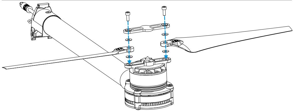
Instructions
- Use two M3x8 screws and four washers to remount propeller.
- Apply thread locker to the thread of the propeller mount first.
- Affix screws with 4Kg.cm (0.4N.m) torque..
Tips: Refer to original screw tensions if unfamiliar with torque measurements. Applying thread locker to the propeller mount first avoids getting thread locker into the holes of the plastic propeller.
Notes: Loose screws cannot be securely locked with thread locker.
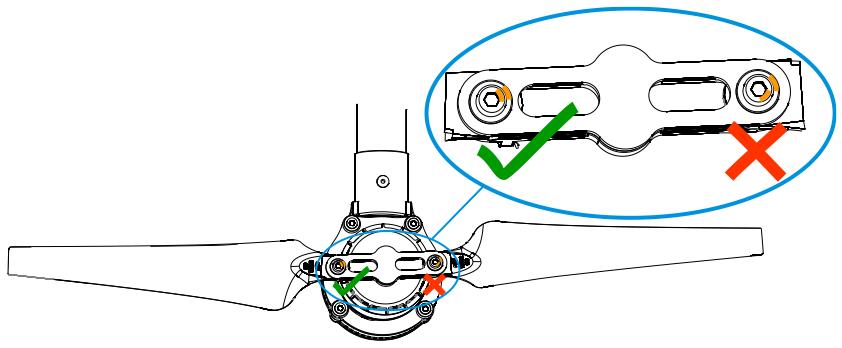
Propeller Precautions
Torque markers on the screws and propeller covers will give you a visual cue to check whether the propellers are loose. Check the torque markers before every flight.
Using Propeller Holder
Instructions
- Insert blades to propeller holder.
- Attach propeller holder to frame arm.
Assembling Motor Vibration Absorbers
A soft gasket is part of the vibration absorber. Assembly of the soft gasket must be carried out as per the diagram below. Assembly is the same for CCW and CW propellers.
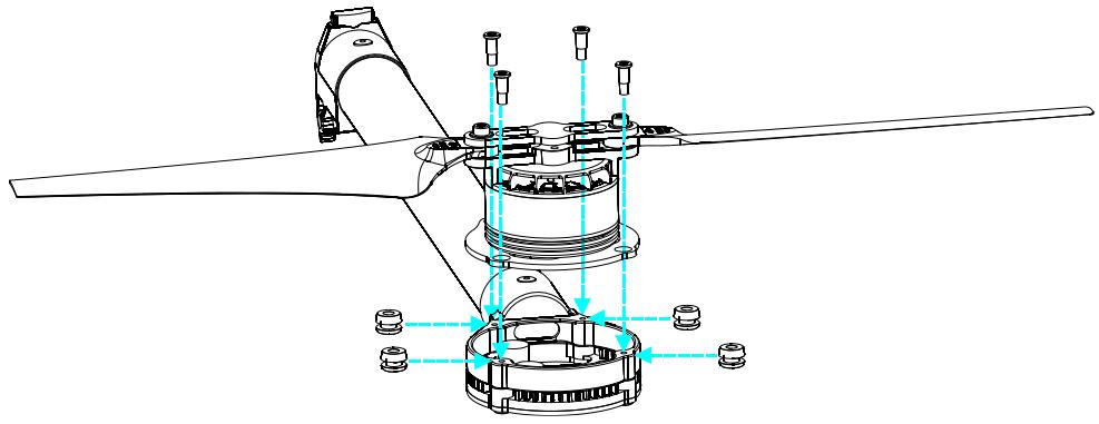
Notes
Ensure all soft dampers and vibration absorbers are in good condition before every flight. If not, replace immediately. Otherwise, the flight performance of your aircraft will be adversely affected.
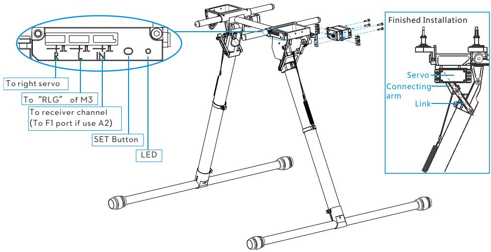
Remounting Landing Gear Servo
Remounting servos is not recommended as they come pre-installed.
Instructions
- Connect left servo cable near M4 to the "RLG" port near M4 on the center frame, then connect the "RLG" port near M3 to the "L" port of the landing gear control board using a servo cable.
- Connect the right servo cable near M7 to the "R" port of the landing gear control board using a servo cable.
- Pressing the SET button using a pin then power on. You will see a yellow LED beside the SET button flashes quickly. Wait as servos complete position initialization.
- Make sure the arm connecting to the servo is parallel to the link. (Shown in the following Fig).
- Assemble the left and right servos to the left and the right parts of the landing gear. Power off.
Recalibrating Servo Travel
Landing gear travel has been pre-calibrated. Mechanical adjustment of gear travel is not recommended.
Instructions
- Keep hands away from all mechanisms.
- Ensure [R], [L] and [IN] connections are correct.
- Keep the whole aircraft off the ground during calibration as landing gear will move.
- Press and hold the SET button using a pin while powering on, then release. An LED will flash yellow quickly. Press the SET button again. Auto calibration will begin and the LED will flash yellow slowly. DO NOT obstruct any moving parts during auto calibration.
- During calibration, the left landing gear will raise and lower, follow by the right landing gear.
- After calibration, both left and right landing gears will be lowered and the LED will be a solid green. This
indicates that the landing gear is working properly.
Notes
(1) If the LED is solid yellow after calibration, a problem has occurred. Carry out Remounting Landing Gear Servo then try again.
(2) Avoid obstructions during calibration. If the landing gear was obstructed, recalibration is required using the above steps.
(3) If [R] and [L] servo cables are reversed, travel will not be measured correctly. Connect correctly and recalibrate the landing gear using the above steps.
Part List
Locate the part that you wish to replace in the following figures, and then order the package that comes with the specified part. The numbering of the part is defined as follow:
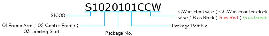
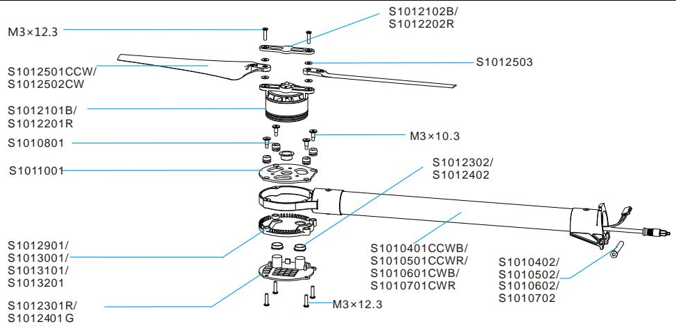
Frame Arm
| Package No. | Name | Part No. |
| 4 | S1000-Premium Frame Arm CCW - Black | S1010401CCWB, S1010402, M3x12.3 |
| 5 | S1000-Premium Frame Arm CCW - Red | S1010501CCWR, S1010502, M3x12.3 |
| 6 | S1000-Premium Frame Arm CW - Black | S1010601CWB, S1010602, M3x12.3 |
| 7 | S1000-Premium Frame Arm CW - Red | S1010701CWR, S1010702, M3x12.3 |
| 8 | S1000-Premium Motor Damping Unit | S1010801, M3x10.3 |
| 10 | S1000-Premium Motor Mount Carbon Board | S1011001, M3x10.3 |
| 21 | S1000-Premium 4114 Motor with black Prop cover | S1012101B, S1012102B, M3x4.5 |
| 22 | S1000-Premium 4114 Motor with red Prop cover | S1012201R, S1012202R, M3x4.5 |
| 23 | S1000-Premium ESC with Red LED | S1012301R, S1012302, M3x12.3 |
| 24 | S1000-Premium ESC with Green LED | S1012401G , S1012402 , M3x12.3 |
| 25 | S1000-Premium Propeller Pack (8) | S1012501CCW , S1012502CW , S1012503 , M3x12.3 |
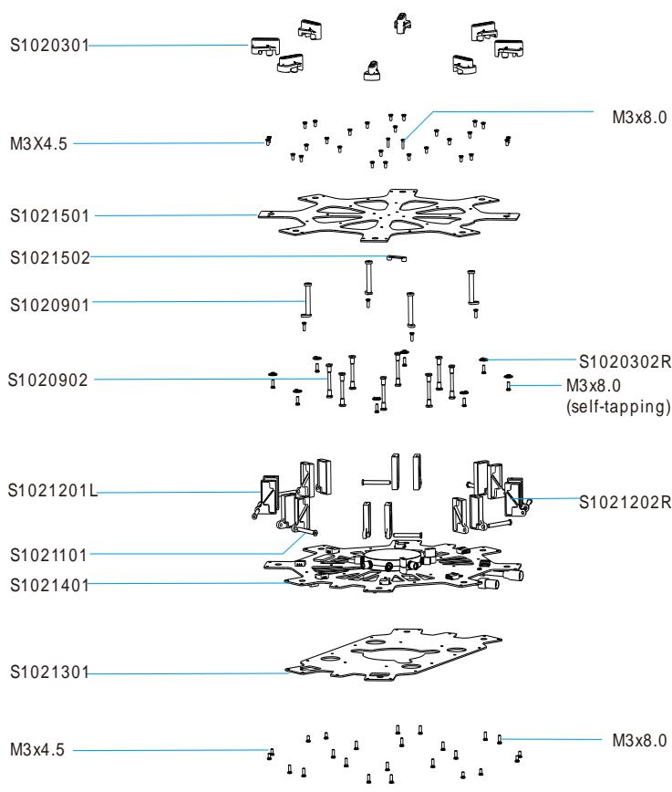
Central Board
| Package No. | Name | Part No. |
| 3 | S1000-Premium Lock Knob | S1020301, S1020302, M3x8.0 (self-tapping) |
| 9 | S1000-Premium Center Frame Support Pillar | S1020901, S1020902, M3x4.5, M3x8.0 |
| 12 | S1000-Premium Arm Mounting Bracket | S1021201L, S1021202R, M3x4.5, M3x8.0, Package 11 |
| 14 | S1000-Premium Center Frame Bottom Board | S1021401, M3x4.5, M3x8.0 |
| 15 | S1000-Premium Center Frame Top Board | S1021501, S1021502, M3x4.5, M3x8.0 |
Landing Gear

Caution : (1) Parts within the dot area are mirrored against each other. Apart from S1031813 and S1031814, they are unique to package 18.
| Package No. | Name | Part No. |
| 16 | S1000-Premium Gimbal Damping Bracket | S1031601, S1031602, S1031603, S1031604, S1031605, M2.5 |
| 17 | S1000-Premium Retractable Module (Right) | S1031701, S1031702, S1031703, S1031704, S1031705, S1031706, S1031707, S1031708, S1031709, S1031710, S1031711, S1031712, M3x4.5 |
| 18 | S1000-Premium Retractable Module (Left) | S1031801, S1031802, S1031803, S1031804, S1031805, S1031806, S1031807, S1031808, S1031809, S1031810, S1031811, S1031812, S1031813, S1031814, M3x4.5 |
| 19 | S1000-Premium Gimbal Damping Connecting Brackets | S1031901, S1031902, S1031903, S1031904, M2.5, M3x8.0 |
| 20 | S1000-Premium Landing Skid | S1032001, S1032002 |
| 26 | S1000-Premium Landing Skid Leg | S1032601, S1032602, S1032603, S1032604, M2.5x8, M2.5x1.3, M3x22 |
| 2 | S1000-Premium Battery Tray | S1030201 |
| 33 | S1000-Premium Gimbal Mounting Accessories | S1033301, S1033302, S1033303, S1033304, S1033305, S1033306, S1033307, S1033308 |
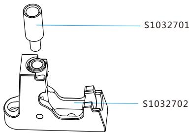
Miscellaneous
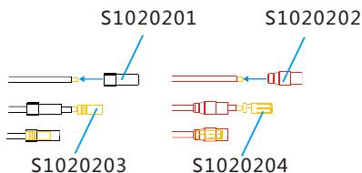
| Package No. | Name | Packages No. |
| 13 | S1000-Premium Center Frame | Package 3, 9, 11, 12, 14, 15, S1021301 |
| 29 | S1000-Premium Complete Arm [CW-RED] | Package 7, 8, 10, 11, 22, 23, 25, S1012901 |
| 30 | S1000-Premium Complete Arm [CW-Green] | Package 6, 8, 10, 11, 21, 24, 25, S1013001 |
| 31 | S1000-Premium Complete Arm [CCW-RED] | Package 5, 8, 10, 11, 22, 23, 25, S1013101 |
| 32 | S1000-Premium Complete Arm [CCW-Green] | Package 4, 8, 10, 11, 21, 24, 25, S1013201 |
| 27 | S1000-Premium GPS Holder | S1032701, S1032702 |
| 28 | S1000-Premium Screw Pack | Assorted screws |
| 1 | S1000-Premium Power Cord Plug | S1020201, S1020202, S1020203, S1020204 |
- Spreading Wings S1000 User Manual
- Disclaimer
- About
- Contents
- Caution
- Assembly Cautions
- Flight Cautions
- Others
- Mounting Landing Gear
- Instructions
- Mounting Frame Arms
- Mounting Electronics and Wiring
- Notes
- Connecting main controller to center frame
- Connecting main controller and landing gear
- Connecting XT60 Ports on Center Frame
- Installing Battery
- Soldering battery connectors
- Installing and connecting battery
- Setting Landing Gear
- Setting up the transmitter
- Notes:
- Usage procedures
- Tips
- Mounting the Gimbal
- Appendix
- Tips:
- FAQ
- Soldering the ESC
- Remounting the Propeller
- Propeller Precautions
- Using Propeller Holder
- Assembling Motor Vibration Absorbers
- Remounting Landing Gear Servo
- Recalibrating Servo Travel
- Part List
Brand : DJI
Model : SPREADING WINGS S1000+ ARF - SPREADING WINGS S900 RTF
Category : Professional drone