
IC-F29SR - Talkie Walkie ICOM - Free user manual and instructions
Find the device manual for free IC-F29SR ICOM in PDF.


| Product type | PMR446 walkie-talkie |
| Brand | ICOM |
| Model | IC-F29SR |
| Power supply | Rechargeable battery (typical 7.4 V Li-ion) |
| Battery life | Not specified |
| Frequency | PMR446 band (446 MHz) |
| Channels | 16 channels |
| CTCSS tones | 50 tones (67.0 - 254.1 Hz) |
| DTCS codes | 84 codes (023 - 754) |
| Main functions | Scan, Priority A/B, Monitor, Siren, Scrambler, Compander, Smart-Ring, Call-Ring, Voice announcement |
| LED indicator | Red, Green, Orange for various states (transmit, receive, low battery, etc.) |
| Protection | IP67 (dust and waterproof with connector cover) |
| Included accessories | Battery, belt clip, connector cover |
| Settings | Beep, beep level, ring level, microphone gain, squelch |
| Programming | CS-F29SR software (optional) to assign functions to keys |
| Programmable keys | 3 keys (Upper, Lower, Top) for assignable functions |
| Weight (approx.) | Approx. 260 g with battery |
| Dimensions (approx.) | Approx. 58 x 110 x 38 mm |
Frequently Asked Questions - IC-F29SR ICOM
User questions about IC-F29SR ICOM
0 question about this device. Answer the ones you know or ask your own.
Ask a new question about this device
Download the instructions for your Talkie Walkie in PDF format for free! Find your manual IC-F29SR - ICOM and take your electronic device back in hand. On this page are published all the documents necessary for the use of your device. IC-F29SR by ICOM.
USER MANUAL IC-F29SR ICOM
OPERATING INSTRUCTIONS
PMR446 TRANSCEIVER
IC-F29SR

INTRODUCTION
FOREWORD
Thank you for purchasing this Icom transceiver.
IMPORTANT
FIRST, CAREFULLY READ INSTRUCTIONS
that are provided with the transceiver.
SAVE THIS OPERATING INSTRUCTIONS—
These operating instructions contain additional important operating instructions for the IC-F29SR PMR446 TRANSCIVER.
TABLE OF CONTENTS
FOREWORD
IMPORTANT
TABLE OF CONTENTS
1 ACCESSORIES 1-2
Accessory attachments 1
Battery pack 1
Belt clip. 1
JACK COVER 2
2 PROGRAMMABLE KEY FUNCTIONS. 3
Programmable key functions 3
3 LED INDICATOR 4
About the LED indicator 4
4 SETTINGS 5-11
Setting the Beep function 5
Setting the beep level. 6
Setting the ringer level. 7
Setting the group code number 8
CTCSS tone setting. 8
DTCS code setting. 9
Setting the microphone gain 10
Setting the squelch level 11
Icom, Icom Inc. and the Icom logo are registered trademarks of Icom Incorporated (Japan) in Japan, the United States, the United Kingdom, Germany, France, Spain, Russia and/or other countries.
All other products or brands are registered trademarks or trademarks of their respective holders.
Accessory attachments
Battery pack
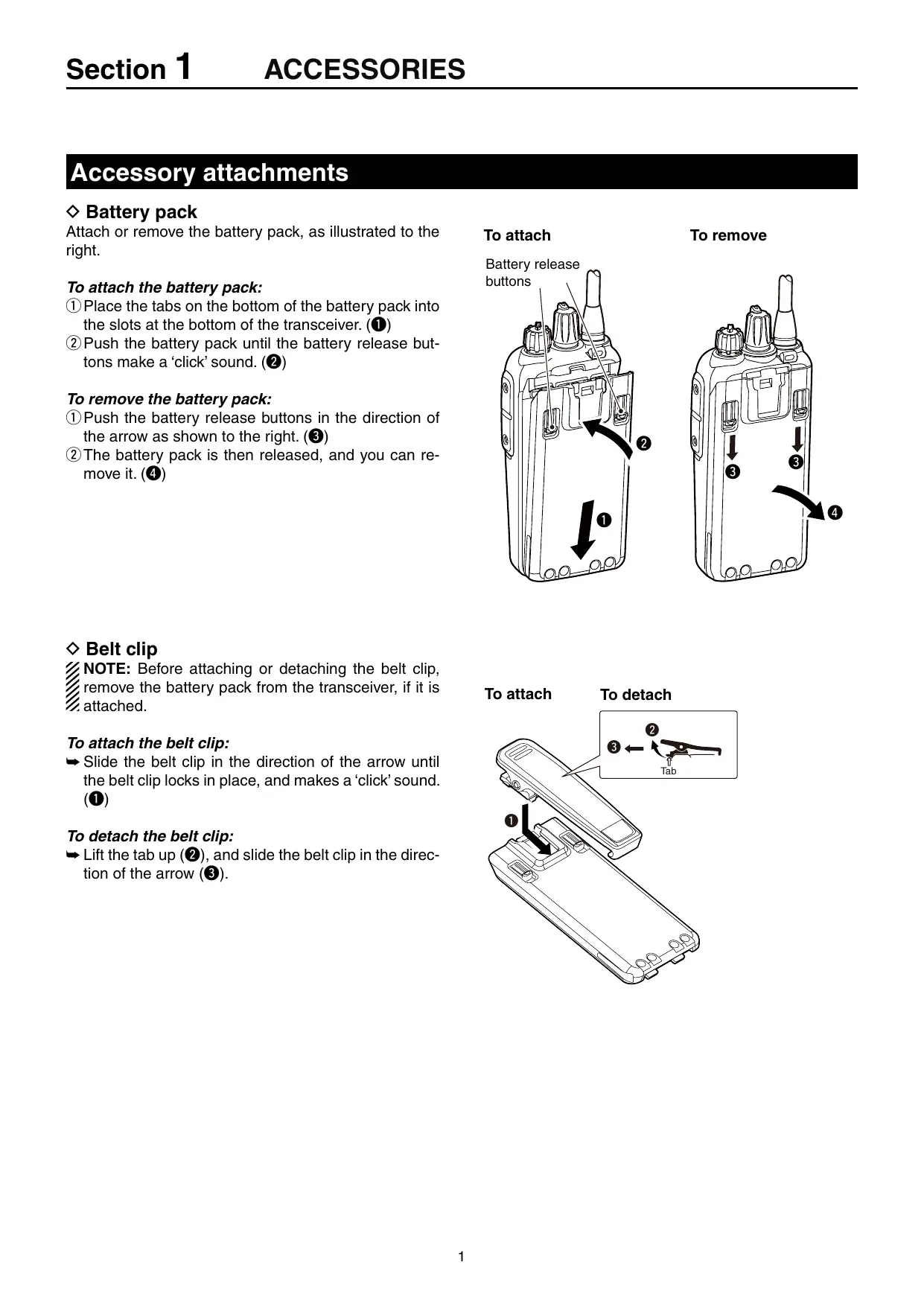
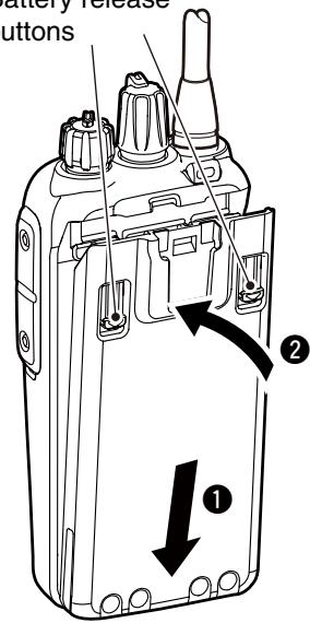
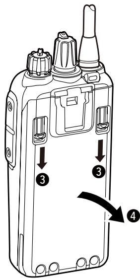
Attach or remove the battery pack, as illustrated to the right.
To attach the battery pack:
① Place the tabs on the bottom of the battery pack into the slots at the bottom of the transceiver. (1)
②Push the battery pack until the battery release buttons make a 'click' sound. (2)
To remove the battery pack:
①Push the battery release buttons in the direction of the arrow as shown to the right. (3)
(2) The battery pack is then released, and you can remove it. (4)
To attach
Battery release buttons
To remove
Belt clip
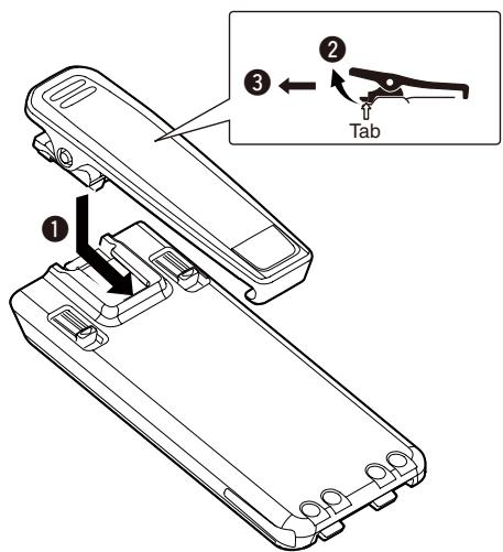
NOTE: Before attaching or detaching the belt clip, remove the battery pack from the transceiver, if it is attached.
To attach the belt clip:
Slide the belt clip in the direction of the arrow until the belt clip locks in place, and makes a 'click' sound. (1)
To detach the belt clip:
Lift the tab up (2), and slide the belt clip in the direction of the arrow (3).
To attach
To detach
Accessory attachments (Continued)
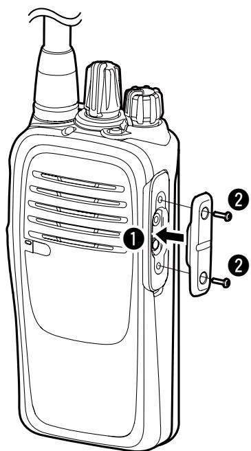
Jack cover
CAUTION: The transceiver meets IP67 requirements for dust-tight and waterproof protection, only when the jack cover or the optional HM-168LWP SPEAKER MICROPHONE is attached.
To attach the jack cover:
① Place the jack cover over the speaker-microphone jack. (1)
② Insert and tighten the screws. (2)
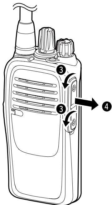
To detach the jack cover:
(1)Unscrew the screws using a Phillips screwdriver. (3)
② Detach the jack cover. (4)
Programmable key functions
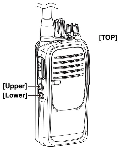
If you use the CS-F29SR CLONING SOFTWARE (purchase separately), you can assign the functions described below to [TOP], [Upper], and [Lower].
NOTE: Refer to the instruction sheet that comes with the transceiver for the default settings of these keys.
SCAN START/STOP
Push to start and cancel a scan.
- When a scan is started with the Power ON Scan or Automatic scan function, push this key to pause it. The paused scan resumes after a set time period.
PRIORITY A CHANNEL, PRIORITY B CHANNEL
Push to select the Priority A or Priority B channel.
PRIORITY A CHANNEL (REWRITE), PRIORITY B CHANNEL (REWRITE)
Push to select the Priority A or Priority B channel.
Hold down to set the operating channel as the Priority A or Priority B channel.
MEMORY CHANNELS 1, 2, 3, 4
Push to select memory channel 1, 2, 3, or 4.
MONI
Push to turn the CTCSS (DTCS) mute ON or OFF.
While holding down this key, the transceiver opens any squelch, or releases any mute.
LOCK
Hold down to turn the Key Lock function ON or OFF.
- Even when the Lock function is ON, [MONI] and [SURVEILLANCE] are not locked.
SURVEILLANCE
Hold down to turn ON the Surveillance function.
Push to turn OFF the function.
- When this function is ON and a signal is received, a beep does not sound and the status indicator does not light, even if you push any key.
SIREN
Hold down to emit a siren sound.
- The transceiver keeps emitting the siren sound until the transceiver's power is turned OFF.
- This function is for situations other than an emergency alert, such as a security alarm.
SCRAMBLER
Hold down to turn ON the Voice Scrambler function.
Push to turn OFF the function.
COMPANDER
Hold down to turn ON the Compander function.
Push to turn OFF the function.
- The Compander function reduces noise components from the transmitted audio to provide clear communication.
S-RING/C-RING
Push to make a Smart-Ring call.
Hold down to make a Call-Ring call.
ANNOUNCE
Push to turn the Channel Announce function ON or OFF.
- The transceiver announces the position of [Rotary Selector].
NOTE: When the Beep function is OFF, the operating channel is not announced, regardless of this setting. (p. 5)
About the LED indicator
The LED indicator indicates the status of various parameters of the transceiver as follows:
(Reference: R is Red, G is Green, O is Orange)
- Cloning (reading or writing data)
- Cloning error (if cloning fails)
- Inh, Blank CH, Unlocked (when you cannot use the channel)
TX Low Battery 1 (while transmitting)
TX Low Battery 2 (while transmitting)
Transmitting
Receiving - Scanning
- Low Battery 1 (You should charge the battery.)
- Low Battery 2 (You must charge the battery.)
- When turning ON the power
- Making a Smart-Ring call
- Lockout, TX Inh, TOT (when transmit is inhibited)
- Smart-Ring call successful
- Smart-Ring call failed
Siren
| R | G | G | G | G | G | G | G | G | G |
| R | G | R | G | R | G | R | G | R | G |
| R | G | R | G | R | G | R | G | R | G |
| R | G | R | G | R | G | R | G | R | G |
| R | G | R | G | R | G | R | G | R | G |
| R | G | R | G | R | G | R | G | R | G |
| G | G | G | G | G | G | G | G | G | G |
| G | G | G | G | G | G | G | G | G | G |
| G | G | G | G | G | G | G | G | G | G |
| G | G | G | G | G | G | G | G | G | G |
| G | G | G | G | G | G | G | G | G | G |
| G | G | G | F | F | F | F | F | F | F |
| G | G | G | F | F | F | F | F | F | F |
| G | G | G | F | F | F | F | F | F | F |
| G | G | G | F | F | F | F | F | F | F |
| G | G | G | F | F | F | F | F | F | F |
| G | G | G | F | G | F | F | F | F | F |
Setting the Beep function
The Beep function can be turned ON or OFF. When it is OFF, the channel announcement is also turned OFF.

NOTE: You should turn ON the Beep function when you set the microphone gain, the squelch level or the group code number to check the current level setting with the beep sounding. (pp. 8-11)
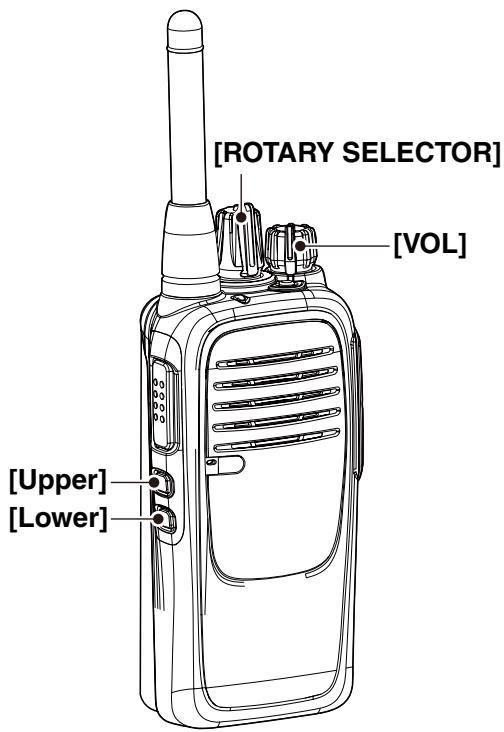
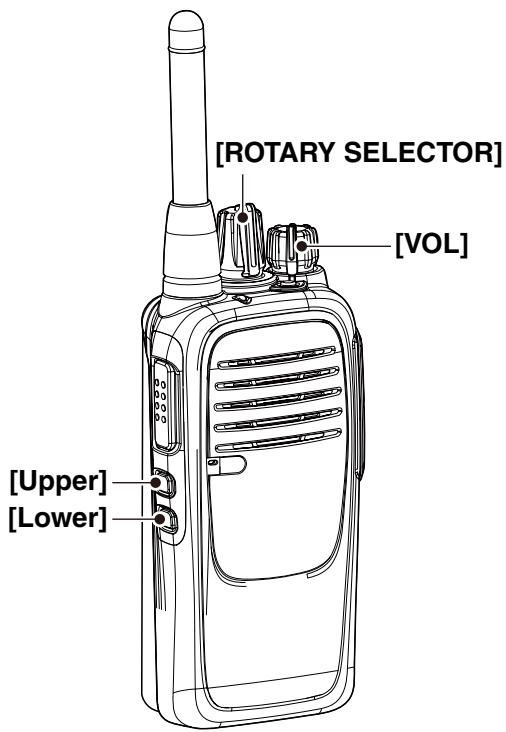
① Rotate [VOL] to turn OFF the transceiver power.
② Set [ROTARY SELECTOR] to any channel other than Channel 16.
(3) While holding down [Lower], rotate [VOL] to turn ON the power to enter the Beep level adjustment mode.
④Push [Lower] to turn the Beep function ON or OFF.
- When a beep sounds after pushing [Lower], the Beep function is ON. When no beep sounds after pushing [Lower], the Beep function is OFF.
- If desired, push [Upper] to adjust the Beep level. See page 6 for details.
⑤ Rotate [VOL] to turn OFF the power to exit the Beep level adjustment mode.
Setting the beep level
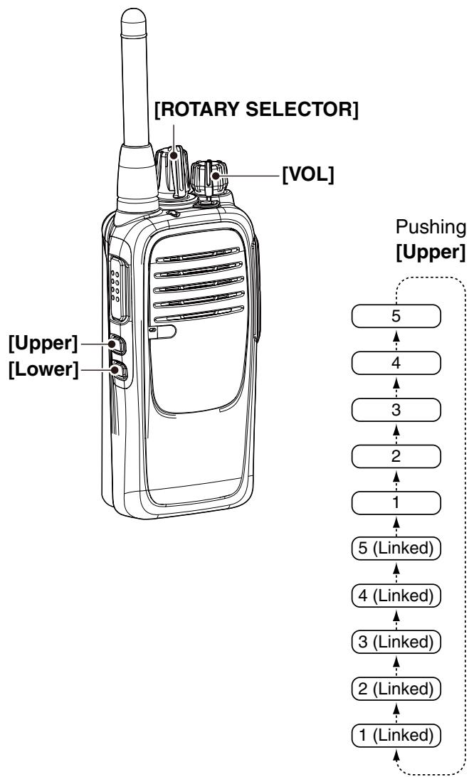
You can adjust the beep level between 1 and 5, or 1 (linked) and 5 (linked).
When a linked option is selected, you can adjust the beep level by rotating [VOL].
① Rotate [VOL] to turn OFF the transceiver power.
② Set [ROTARY SELECTOR] to any channel other than Channel 16.
(3) While holding down [Lower], rotate [VOL] to turn ON the power and enter the beep level adjustment mode.
(4) Push [Upper] to change the beep level as shown to the right.
- A beep sounds every time you push [Upper]. Therefore, you can determine the current level setting by the increasing loudness of the beep that sounds.
- To determine if you have selected a linked level, set [VOL] to minimum, then push [Upper] repeatedly, listening for the loudest beep (level 5). Pushing [Upper] once after the loudest beep will select 1 (Linked). Repeatedly push [Upper] to select the desired linked level.
⑤ Rotate [VOL] to turn OFF the power to exit the beep level adjustment mode.
Setting the ringer level
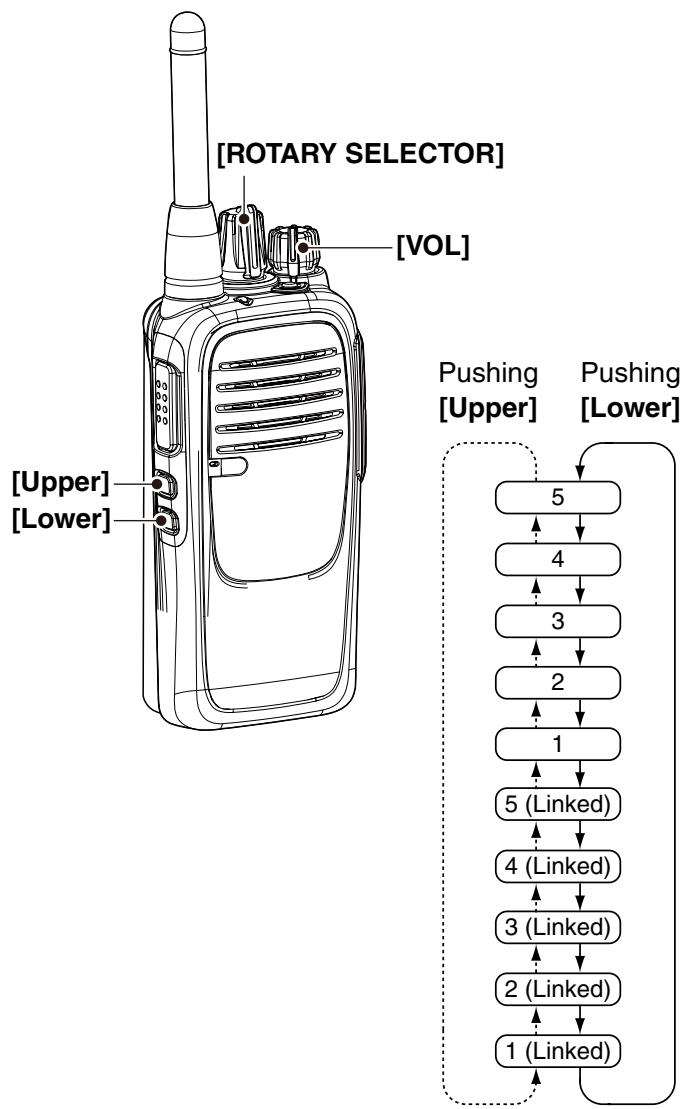
You can adjust the ringer level between 1 and 5, or 1 (linked) and 5 (linked).
When a linked option is selected, you can adjust the ringer level by rotating [VOL].
① Rotate [VOL] to turn OFF the power.
② Set [ROTARY SELECTOR] to Channel 16.
(3) While holding down [Lower], rotate [VOL] to turn ON the power and enter the ringer level adjustment mode.
Push [Upper] to increase, or push [Lower] to decrease the ringer level as shown to the right.
- A beep sounds after pushing [Upper]. Therefore, you can determine the current level setting by the increasing loudness of the beep that sounds.
- To determine if you have selected a linked level, set [VOL] to minimum, then push [Upper] up to 10 times, listening for the loudest beep (level 5). Pushing [Upper] once after the loudest beep will select 1 (Linked). Repeatedly push [Upper] or [Lower] to select the desired linked level.
⑤ Rotate [VOL] to turn OFF the power to exit the ringer level adjustment mode.
Setting the group code number
CTCSS tone setting
The transceiver is equipped with 50 CTCSS tones.
CTCSS operation enables silent standby, since you will only receive calls from group members using the same CTCSS tone.
① Rotate [VOL] to turn OFF the power.
② Set [ROTARY SELECTOR] to any channel other than Channel 16.
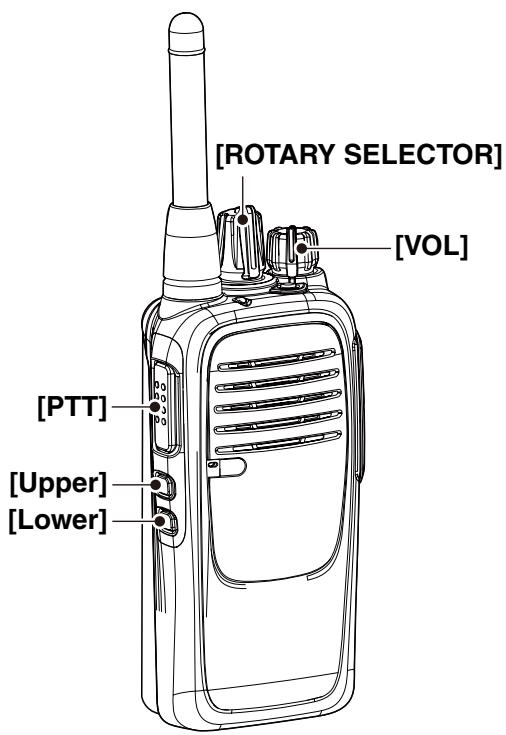
(3) While holding down [PTT], [Upper], and [Lower], rotate [VOL] to turn ON the power.
④ Rotate [ROTARY SELECTOR] to select the desired channel (1 to 16) that you want to assign the CTCSS tone to.
⑤ Hold down [Upper] until two beeps sound.
- The transceiver enters the CTCSS tone setting mode.
Push [PTT] the necessary number of times to enter the ten's digit of the desired CTCSS tone number (grey column) as shown in the list below.
⑦Push [Upper].
- The selected number will be announced.
Push [PTT] the necessary number of times to enter the one's digit of the desired CTCSS tone number (grey column) as shown in the list below.
Push [Upper] to complete the setting.
- The selected number will be announced.
⑩Turn OFF the power to exit the CTCSS tone setting mode.
NOTE:
- If you make a mistake, go back to step ① and follow all the steps again.
- If you want to enter "0," do not push [PTT] in step ⑤ and ⑦, just push [Upper]. Then "zero" will be announced. To turn OFF the CTCSS tone, enter "00."
[Example]: CTCSS tone No. 28 (162.2 Hz) assigned to channel 4
① Rotate [VOL] to turn OFF the power.
(2) While holding down [PTT], [Upper], and [Lower], rotate [VOL] to turn ON the power.
- The transceiver enters CTCSS tone Setting mode.
③ Rotate [ROTARY SELECTOR] to select channel 4, then hold down [Upper] until two beeps sound.
Push [PTT] two times to enter “2” (the ten's digit) of the number 28.
⑤Push [Upper].
"Two" will be announced.
(6)Push [PTT] eight times to enter “8” (the one’s digit) of the number 28.
⑦Push [Upper] to complete the setting.
"Eight" will be announced.
(8) Turn OFF the power to set the CTCSS tone.
![ICOM IC-F29SR - [Example]: CTCSS tone No. 28 (162.2 Hz) assigned to channel 4 - 1](/content/2024/11/218513/images/77003f47c213b8ac9cbdbf79557a947a581ca1eeda8845fbff4df2b04a19e363.jpg)
Available CTCSS tone list
(Hz)
| No. | Freq. | No. | Freq. | No. | Freq. | No. | Freq. | No. | Freq. |
| 01 | 67.0 | 11 | 94.8 | 21 | 131.8 | 31 | 171.3 | 41 | 203.5 |
| 02 | 69.3 | 12 | 97.4 | 22 | 136.5 | 32 | 173.8 | 42 | 206.5 |
| 03 | 71.9 | 13 | 100.0 | 23 | 141.3 | 33 | 177.3 | 43 | 210.7 |
| 04 | 74.4 | 14 | 103.5 | 24 | 146.2 | 34 | 179.9 | 44 | 218.1 |
| 05 | 77.0 | 15 | 107.2 | 25 | 151.4 | 35 | 183.5 | 45 | 225.7 |
| 06 | 79.7 | 16 | 110.9 | 26 | 156.7 | 36 | 186.2 | 46 | 229.1 |
| 07 | 82.5 | 17 | 114.8 | 27 | 159.8 | 37 | 189.9 | 47 | 233.6 |
| 08 | 85.4 | 18 | 118.8 | 28 | 162.2 | 38 | 192.8 | 48 | 241.8 |
| 09 | 88.5 | 19 | 123.0 | 29 | 165.5 | 39 | 196.6 | 49 | 250.3 |
| 10 | 91.5 | 20 | 127.3 | 30 | 167.9 | 40 | 199.5 | 50 | 254.1 |
| 00 | OFF |
Setting the group code number (Continued)
DTCS code setting
This transceiver is equipped with 84 DTCS codes. DTCS operation enables silent standby, since you will only receive calls from group members using the same DTCS code.
① Rotate [VOL] to turn OFF the power.
② Set [ROTARY SELECTOR] to any channel other than Channel 16.
(3) While holding down [PTT], [Upper], and [Lower], rotate [VOL] to turn ON the power.
④ Rotate [ROTARY SELECTOR] to select the desired channel (1 to 16) that you want to assign the DTCS code to.
⑤ Hold down [Lower] until two beeps sound.
- The transceiver enters the DTCS code setting mode.
⑥Push [PTT] the necessary number of times to enter the ten's digit of the desired DTCS code number (grey column) as shown in the list below.
⑦Push [Upper].
- The selected number will be announced.
Push [PTT] the necessary number of times to enter the one's digit of the desired DTCS code number (grey column) as shown in the list below.
⑨Push [Upper].
- The selected number will be announced.
If you want to use Inverse mode, push [PTT] again.
- If you want to use Normal mode, skip this step.
⑪Push [Upper] to complete the setting.
⑫Turn OFF the power to exit the DTCS Code Setting mode.
NOTE:
If you make a mistake, go back to step ① and follow all the steps again.
If you want to enter "0", do not push [PTT] in step ⑤ and ⑦, just push [Upper]. Then "zero" will be announced. To turn OFF the DTCS code, enter "0."
[Example]: DTCS code No. 16 (114) Inverse mode assignment to channel 5
① Rotate [VOL] to turn OFF the power.
(2) While holding down [PTT], [Upper], and [Lower], rotate [VOL] to turn ON the power.
The transceiver enters DTCS Code Setting mode.
③ Rotate [ROTARY SELECTOR] to select channel 5, then hold down [Lower] until two beeps sounds.
④Push [PTT] one time to enter “1” (the ten's digit) of the number 16.
⑤Push [Upper].
- "One" will be announced.
⑥Push [PTT] six times to enter “6” (the one’s digit) of the number 16.
⑦Push [Upper].
"Six" will be announced.
Push [PTT] again, to use Inverse mode.
Push [Upper] to complete the setting.
⑩Turn OFF the power to set the DTCS code.
Available DTCS code list
| No. | Code | No. | Code | No. | Code | No. | Code | No. | Code |
| 01 | 023 | 21 | 132 | 41 | 271 | 61 | 466 | 81 | 732 |
| 02 | 025 | 22 | 134 | 42 | 306 | 62 | 503 | 82 | 734 |
| 03 | 026 | 23 | 143 | 43 | 311 | 63 | 506 | 83 | 743 |
| 04 | 031 | 24 | 152 | 44 | 315 | 64 | 516 | 84 | 754 |
| 05 | 032 | 25 | 155 | 45 | 331 | 65 | 532 | 00 | OFF |
| 06 | 036 | 26 | 156 | 46 | 343 | 66 | 546 | ||
| 07 | 043 | 27 | 162 | 47 | 346 | 67 | 565 | ||
| 08 | 047 | 28 | 165 | 48 | 351 | 68 | 606 | ||
| 09 | 051 | 29 | 172 | 49 | 364 | 69 | 612 | ||
| 10 | 054 | 30 | 174 | 50 | 365 | 70 | 624 | ||
| 11 | 065 | 31 | 205 | 51 | 371 | 71 | 627 | ||
| 12 | 071 | 32 | 223 | 52 | 411 | 72 | 631 | ||
| 13 | 072 | 33 | 226 | 53 | 412 | 73 | 632 | ||
| 14 | 073 | 34 | 243 | 54 | 413 | 74 | 654 | ||
| 15 | 074 | 35 | 244 | 55 | 423 | 75 | 662 | ||
| 16 | 114 | 36 | 245 | 56 | 431 | 76 | 664 | ||
| 17 | 115 | 37 | 251 | 57 | 432 | 77 | 703 | ||
| 18 | 116 | 38 | 261 | 58 | 445 | 78 | 712 | ||
| 19 | 125 | 39 | 263 | 59 | 464 | 79 | 723 | ||
| 20 | 131 | 40 | 265 | 60 | 465 | 80 | 731 |
Setting the microphone gain
Higher levels make the microphone more sensitive to the user's voice.
① Rotate [VOL] to turn OFF the power.
② Set [ROTARY SELECTOR] to Channel 16.
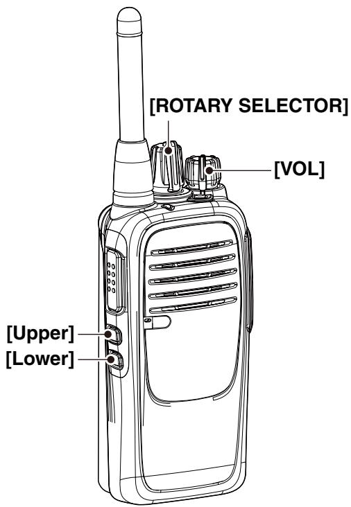
(3) While holding down [Upper], rotate [VOL] to turn ON the power and enter the microphone gain adjustment mode.
④Push [Upper] or to increase, or push [Lower] to decrease the microphone gain.
- The adjustable range is 1 (minimum) to 4 (maximum).
- A beep sounds after pushing [Upper] or [Lower].
An error beep sounds if you try to exceed the adjustable range.
NOTE: The Beep function should be turned ON. (p. 5)
⑤Rotate [VOL] to turn OFF the power to exit the microphone gain adjustment mode.
Setting the squelch level
The squelch circuit mutes the received audio signal, depending on the signal strength.
① Rotate [VOL] to turn the transceiver power OFF.
② Set [ROTARY SELECTOR] to any channel other than Channel 16.
(3) While holding down [Upper], rotate [VOL] to turn ON the power and enter the squelch level adjustment mode.
④Push [Upper] to increase the squelch level (tight squelch), or push [Lower] to decrease the squelch level (loose squelch).
- The adjustable range is 0 (open squelch) and 1 (loose squelch) to 9 (tight squelch).
- A beep sounds after pushing [Upper] or [Lower]. An error beep sounds if you try to exceed the adjustable range.
NOTE: The Beep function should be turned ON. (p. 5)
⑤Rotate [VOL] to turn OFF the power to exit the squelch level adjustment mode.
- INTRODUCTION
- FOREWORD
- IMPORTANT
- FIRST, CAREFULLY READ INSTRUCTIONS
- SAVE THIS OPERATING INSTRUCTIONS—
- TABLE OF CONTENTS
- Accessory attachments
- Battery pack
- To attach the battery pack:
- To remove the battery pack:
- Belt clip
- To attach the belt clip:
- To detach the belt clip:
- Accessory attachments (Continued)
- Jack cover
- To attach the jack cover:
- To detach the jack cover:
- Programmable key functions
- SCAN START/STOP
- PRIORITY A CHANNEL, PRIORITY B CHANNEL
- PRIORITY A CHANNEL (REWRITE), PRIORITY B CHANNEL (REWRITE)
- MEMORY CHANNELS 1, 2, 3, 4
- MONI
- LOCK
- SURVEILLANCE
- SIREN
- SCRAMBLER
- COMPANDER
- S-RING/C-RING
- ANNOUNCE
- About the LED indicator
- Setting the Beep function
- Setting the beep level
- Setting the ringer level
- Setting the group code number
- CTCSS tone setting
- NOTE:
- [Example]: CTCSS tone No. 28 (162.2 Hz) assigned to channel 4
- Setting the group code number (Continued)
- DTCS code setting
- Setting the microphone gain
- Setting the squelch level
Brand : ICOM
Model : IC-F29SR
Category : Talkie Walkie