M4029Q - Surveillance Camera IT WORKS - Free user manual and instructions
Find the device manual for free M4029Q IT WORKS in PDF.
| Product Type | Surveillance Camera |
| Brand | IT WORKS |
| Model | M4029Q |
| Resolution | 1080p Full HD |
| Viewing Angle | 110° |
| Night Vision | Infrared up to 10 meters |
| Power Supply | 12V DC power adapter |
| Power Consumption | 5 W |
| Dimensions (L x W x H) | 100 x 60 x 60 mm |
| Weight | 250 g |
| Connectivity | Wi-Fi 2.4 GHz, Ethernet RJ45 |
| Storage | microSD card up to 128 GB |
| Motion Detection | Yes, with push notification |
| Two-way Audio | Built-in microphone and speaker |
| Protection Rating | IP65 (weather-resistant) |
| Operating Temperature | -10°C to 50°C |
| Cleaning | Clean with a soft, dry cloth |
| Security | WPA2 encryption, user authentication |
| Spare Parts | Power adapter, Ethernet cable, mounting kit |
| Repairability | Repairability index 7.5/10 |
| Warranty | 2 years |
Frequently Asked Questions - M4029Q IT WORKS
User questions about M4029Q IT WORKS
0 question about this device. Answer the ones you know or ask your own.
Ask a new question about this device
Download the instructions for your Surveillance Camera in PDF format for free! Find your manual M4029Q - IT WORKS and take your electronic device back in hand. On this page are published all the documents necessary for the use of your device. M4029Q by IT WORKS.
USER MANUAL M4029Q IT WORKS
For Camera models with the firmware version 4.40 or above
June. 7 ^th , 2016
Seyeon Technology Co., Ltd
www.seyeon.co.kr
www.flexwatch.com

Copyright Information
Copyright 2016 Seyeon Tech Co., Ltd. All rights reserved. Use of this product and manual is subject to license. Information in this document is subject to change without notice. FlexWATCH® is registered trademark of products of Seyeon Tech Co., Ltd. All other brand and product names mentioned in this document are registered trademarks or trademarks of their respective holders. The Software supplied with these Products is provided under license from Seyeon Tech Co., Ltd.

GNU General Public License Information
This product includes certain open source or other software originated from third parties that is subject to the GNU General Public License (GPL), GNU Library/Lesser General Public License (LGPL), and different and/or additional copyright licenses, disclaimers, and notices.
The exact terms of GPL, LGPL, and some other licenses are provided to you with this product. Please refer to the exact terms of the GPL and LGPL at http://www.fsf.org (Free Software Foundation) or http://www.opensource.org (Open Source Initiative) regarding your rights under said license. In accordance with the terms of the GPL and LGPL, you may obtain a copy of the relevant source code by sending your request to sales@flexwatch.com. Subject to GPL, you may re-use, re-distribute and modify the GPL source code.
Note that with respect solely to the GPL Software, no warranty is provided. We do not offer direct support for the distribution. This offer is valid for up to three years from the date of original purchase of the Product.

Precaution on microSD card
√ Do not use force, a thin stick or tweezers to remove the microSD card. If you cannot remove the microSD card, contact customer support.
√ To prevent any data damage, follows the below caution. We do not provide any guarantee for damaged data
- Do not remove a memory card or Do not turn off the IP Camera while reading or writing data,
- Do not operate the IP Camera in the location where static charge or electrical noise is present.
√ Do not remove the microSD card while IP Camera is recording. Disable the Recording configuration first and then turn off the IP Camera before removing microSD card. Do not insert a deformed microSD card into the Reader.
√ Do not try to access microSD card extracted from IP Camera on Windows PC or other devices. If Linux file system like ext3, ext4 is not installed, It may destroy all data of microSD card.
√ Regular maintenance by formatting microSD card in every 6 months is highly recommended as microSD card could be damaged by physical, or electrical characteristics. or its file system may be fragmented, resulted in degradation in performance by repeated access.
√ Formatting microSD card will delete all files stored on it. You may use FlexWATCH SmartPlayer to back up the recorded video stream as AVI file before formatting
1. Contents
- Contents....3
- Introduction 6
- Web Admin Page....7
3.1 Entering the Web Admin Page....7
3.2 Web Admin Menu Navigation....8
- Basic Setup....10
4.1 Network 10
4.1.1 IP Address....10
4.1.2 Web Port 10
4.1.3 RTP/RTSP....10
4.2 Video & Audio 10
4.2.1 Video Streams 10
4.2.2 Primary Stream 10
4.2.3 Secondary Stream 10
4.2.4 Tertiary Stream 10
- Video & Device....11
5.1 Video Streams....11
5.1.1 Camera Settings 13
5.1.2 Primary Stream / Secondary Stream / Tertiary Stream 19
5.2 Motion Detection....20
5.3 ROI (Region of Interest) 21
5.4 Privacy Zone 22
5.5 Serial Ports 24
5.5.1 Serial Input Mode....24
5.5.2 Serial Output Mode....25
5.5.3 Transparent Mode 26
5.5.4 PTZ Mode [for FW3170 / FW1173 / FW1175 / FW1176 Models only]....26
5.6 DI (Sensor Input) / DO (Alarm Output) 29
5.7 DI Status / DO Control....29
- Recording 31
6.1 Disk Setting....31
6.1.1 Disk Status & Format....31
6.1.2 Disk Information....33
6.1.3 Disk Circulation 34
6.1.4 Disk Status Report....34
6.2 Recording Setting....35
6.3 Recording Profile....39
6.4 Clear Setting....39
6.5 Delete Recorded Data 40
7. Network 41
7.1 IP Address....41
7.1.1 Static IP....41
7.1.2 DHCP Client 42
7.1.3 PPPoE 43
7.2 Web Port 43
7.3 RTP / RTSP 43
7.3.1 RTSP URL 44
7.4 Bandwidth 45
7.5 View Network Status....45
7.6 Network Status Notify....46
7.7 DDNS 47
7.8 UPnP....51
7.8.1 UPnP Port Forwarding....51
7.8.2 Display Shortcut Icon in My Network Place....52
7.9 SNMP....52
7.10 HTTPS 53
7.11 Zeroconf....54
7.12 IP Filtering 54
8. System....56
8.1 Name....56
8.2 Hostname....57
8.3 Date & Time 57
8.4 Admin.Password....58
8.5 Access Level 59
8.6 User 60
8.6.1 Add 60
8.6.2 Edit 62
8.6.3 Delete....62
9. Advanced....63
9.1 Advanced Services....63
9.1.1 E-mail 63
9.1.2 FTP (Buffered) 68
9.1.3 FTP (Periodic) 72
9.1.4 Sensor Notification....75
9.1.5 Alarm Output 78
10. Utilities 81
10.1 Log....81
10.2 Reboot....81
10.3 Restore Default 82
10.4 System Update....82
2. Introduction
This manual covers the FlexWATCH ^® camera models with firmware version 4.30-B3 or above.
Note: All instructions and information in this manual are valid for FlexWATCH ^® devices mentioned above unless otherwise stated.
3. Web Admin Page
Most of the features in the FlexWATCH ^® device can be set up by an authorized user or an administrator via the Web Admin Page.
3.1 Entering the Web Admin Page
To login to the Web Admin Page, follow the steps below:
1) Enter the IP Address or Domain Name of the FlexWATCH® device at the address bar on your web browser.
Note: We recommend Internet Explorer as a web browser for using FlexWATCH devices. The initial IP setting for the FlexWATCH ^® device can be done through IP Installer software which can be found in the enclosed CD or software download page at FlexWATCH ^® Web Site (http://www.FlexWATCH ^® .com/support/download/software.asp).
2) When connected to the FlexWATCH ^® device via the web browser successfully, the device home page will be displayed as shown below.
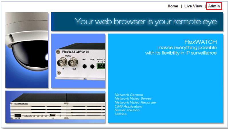
3) Click Admin at the upper right corner of the device home page.
4) Enter User name and Password when an authentication window is appeared as shown below, and then click OK.
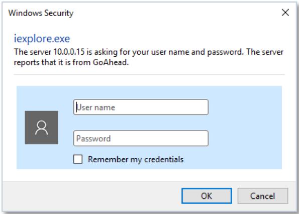
Note: The default user name and password is "root".
5) The Web Admin Page will appear as shown below when the login is successfully finished.
| Basic Setup This category shows the detailed method for Quick Configuration. | |
| IP Address | Configuration of Network(IP,Netmask,DNS). |
| Web Port | Modification of HTTP and other application network port numbers. |
| RTP/RTSP | Configuration of RTP/RTSP. |
| Video Streams | Configuration of video mode and the details. |
| Primary Stream | Configuration of primary stream. |
| Secondary Stream | Configuration of secondary stream. |
3.2 Web Admin Menu Navigation
The following table shows the hierarchy of the Web Admin Page menu structure:
| Category | Main Menu | Level 1 Sub-Menu | Level 2 Sub-Menu |
| Basic Setup | Network | IP AddressWeb PortRTP/RTSP | N/A |
| Video & Audio | Video StreamPrimary StreamSecondary Stream | N/A | |
| Video & Device | Video Stream | Camera SettingsPrimary StreamSecondary StreamTertiary Stream | N/A |
| Motion Detection | N/A | N/A | |
| ROI | N/A | N/A | |
| Privacy Zone | N/A | N/A | |
| PTZ | PTZ OSD MenuPTZ Preset | N/A | |
| Serial Ports | Serial Input ModeSerial Output ModeTransparent ModePTZ Mode | ||
| DI/DO | N/A | N/A | |
| DI Status/DO Control | N/A | N/A | |
| Recording | Disk Setting | Disk Status & FormatDisk InformationDisk CirculationDisk Status Report | N/A |
| Recording Setting | Built-in Module 0 | Camera 1Camera 2Camera 3 | |
| Camera 4 | |||
| Recording Profile | N/A | N/A | |
| Clear Setting | N/A | N/A | |
| Delete Recorded Data | N/A | N/A | |
| Network | IP Address | N/A | N/A |
| Web Port | N/A | N/A | |
| RTP/RTSP | N/A | N/A | |
| Bandwidth | N/A | N/A | |
| Network Status | N/A | N/A | |
| Network Status Notify | N/A | N/A | |
| DDNS | N/A | N/A | |
| UPnP | N/A | N/A | |
| SNMP | N/A | N/A | |
| HTTPS | N/A | N/A | |
| Zeroconf | N/A | N/A | |
| IP Filtering | N/A | N/A | |
| System | Name | N/A | N/A |
| Hostname | N/A | N/A | |
| Date & Time | N/A | N/A | |
| Admin. Password | N/A | N/A | |
| Access Level | N/A | N/A | |
| User | N/A | N/A | |
| Advanced | Advanced Services | EmailFTP (Buffered)FTP (Periodic)Sensor NotificationAlarm Output | Camera 1Camera 2Camera 3Camera 4 |
| Utilities | Log | N/A | N/A |
| Reboot | N/A | N/A | |
| Restore Default | N/A | N/A | |
| Update | N/A | N/A |
4. Basic Setup
Basic Setup provides shortcuts to the settings that should be made before using the FlexWATCH ^® device.
4.1 Network
4.1.1 IP Address
Please see page 39.
4.1.2 Web Port
Please see page 41.
4.1.3 RTP/RTSP
Please see page 41.
4.2 Video & Audio
4.2.1 Video Streams
Please see page 10.
4.2.2 Primary Stream
Please see page 17.
4.2.3 Secondary Stream
Please see page 17.
4.2.4 Tertiary Stream
Please see page 17.
5. Video & Device
Video, Audio, Motion Detection, Streaming and External device related settings are available in this menu.
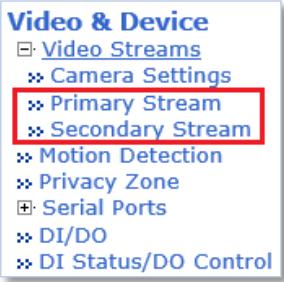
5.1 Video Streams
Note: Video stream settings page may vary depending on the model number or firmware version. Please check the device model number first before you read the information below.
For Dual Stream Camera Models
Video Streams
| Max Frame Rate | 30 fps 25 fps | |
| Video with Flexible Extra System data | Enable | |
| Video with user defined message | Enable | |
| Video with PPP status | Enable | |
| Video with camera name | Enable | |
| Video with server name | Enable | |
| Video with IP address | Enable | |
| Time Stamp | On Off | |
| Primary Stream | Frame Rate | 30 fps |
| Image Size | 1920 x 1080 | |
| Encoding Standard | M-JPEG H.264 | |
| Audio | Enable Disable | |
| Secondary Stream | Frame Rate | 10 fps |
| Image Size | 320 x 176 | |
| Encoding Standard | M-JPEG H.264 | |
| Audio | Enable Disable | |
Back
Apply
| » Camera Settings |
| » Primary Stream |
| » Secondary Stream |
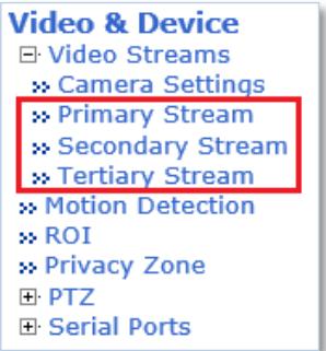
For Triple Stream Camera Models
Video Streams
| Max Frame Rate | 30 fps 25 fps | |
| Video with Flexible Extra System data | Enable | |
| Video with user defined message | Enable | |
| Video with PPP status | Enable | |
| Video with camera name | Enable | |
| Video with server name | Enable | |
| Video with IP address | Enable | |
| Time Stamp | On Off | |
| TV Out | Enable Disable | |
| Primary Stream | Frame Rate | 30 fps |
| Image Size | 2048 x 1536 | |
| Encoding Standard | M-JPEG H.264 | |
| Audio | Enable Disable | |
| Secondary Stream | Frame Rate | 30 fps |
| Image Size | 704 x 480 | |
| Encoding Standard | M-JPEG H.264 | |
| Audio | Enable Disable | |
| Tertiary Stream | Frame Rate | 30 fps |
| Image Size | 320 x 240 | |
| Encoding Standard | M-JPEG H.264 | |
| Audio | Enable Disable | |
Back
Apply
» Camera Settings
» Primary Stream
» Secondary Stream
» Tertiary Stream
| Max. Video Encoding | 3M x 30 fps |
Apply
- Max Frame Rate: Depending on the power frequency can operate the device with NTSC (30FPS) or PAL (25FPS).
■ Video with UART Flexible Extra System Data: If Enabled, video data will contain UART sensor data from COM port.
■ Video with User defined message: If Enabled, video data will contain the user-defined message data.
■ Video with PPP status: If enabled, video data will contain PPP connection status.
■ Video with Camera name: If enabled, video data will contain the camera name defined by user.
■ Video with IP address: If enabled, video data will contain the IP address of the FlexWATCH® device.
■ Time Stamp: If enabled, video data will contain the time stamp.
■ Frame Rate: FPS (Frame Rate per Second) can be set to the video streams independently. Available FPS are follows: 30 / 15 / 10 / 7.5 / 5 / 3.75 / 3 / 2 / 1
■ Encoding Standard: Select the compression type for each stream, either M-JPEG or H.264.
■ Image Size: Select the image size for each video stream.
To check the supported resolution, please refer to the resolution tables below
■ Audio: Select if Audio function is to be used. Bi-directional (Two-way) Audio is supported.
Primary Stream
| Camera Model | QXGA | Full HD | SXGA (HD) | D1 | CIF | QCIF |
| VGA series | - | - | - | 640 x 480 | 320 x 240 | 160 x 112 |
| 1.3 Megapixel Series | - | - | 1280 x 1024 | 704 x 480 | 320 x 240 | 160 x 112 |
| 2.0 Megapixel Series | - | 1920 x 1080 | 1280 x 720 | 704 x 480640 x 352 | 320 x 176 | 160 x 96 |
| 3.0 Megapixel Series | 2048 x 1536 | - | 1280 x 1024 | 640 x 480 | 320 x 240 | 160 x 112 |
Secondary Stream
| Camera Model | D1 | CIF | QCIF |
| VGA series | 640 x 480 | 320 x 240 | 160 x 112 |
| 1.3 Megapixel Series | 704 x 480 | 320 x 240 | 160 x 112 |
| 2.0 Megapixel Series | 704 x 480640 x 352 | 320 x 176 | 160 x 96 |
| 3.0 Megapixel Series | 640 x 480 | 320 x 240 | 160 x 112 |
Tertiary Stream
| Camera Model | CIF | QCIF |
| 3.0 Megapixel Series | 320x240 | 160x112 |
- Max. Video Encoding: Select maximum resolution and frame rate of primary stream for the FlexWATCH® device.
Available options are follows: 2M x 30fps, 2M x 60fps, 3M x 30fps
Note: Depending on the camera model, Max. Video Encoding option may not be supported.
5.1.1 Camera Settings
This setting page provides image related settings for the FlexWATCH ^® device.
For following camera models: FW1173-FX, FW1174-FC, FW1175-FM, FW1175-FX, FW1176-FM, FW1176-FX, FW7501-FC3, FW7504-FTM, FW7504-FTV, FW7601-FTM, FW7601-FTV, FW7601-FC3, FW7901-FTM, FW7901-FTV, FW7901-FC3
| Lens Type | DC Iris ○ Manual Iris | |
| Noise Filter | Off ○ On | |
| Brightness | 144 | (Default:144, 0 ~ 256) |
| Contrast | 16 | (Default:16, 0 ~ 30) |
| Sharpness | 3 | (Default:3, 0 ~ 5) |
| AGC Gain | 50 | (Default:50, 1 ~ 126) |
| Sens Up Level | 0 | (Default:0, 0 ~ 5) |
| WDR | Off ○ On | |
| Day & Night Control | Auto √ | |
| Day & Night Dwelling Time | 4 | sec (Default:4, 0 ~ 255) |
| Day & Night Detect | Internal ○ External | |
| The threshold of day to night | 15 | (Default:15, 1 ~ 32) |
| The threshold of night to day | 3 | (Default:3, 1 ~ 32) |
| Vertical Flip | Disable ○ Enable | |
| Horizontal Flip | Disable ○ Enable | |
| Manual Shutter Enable | Disable ○ Enable | |
| Video Output | Disable ○ Enable | |
| Video Output Channel | Primary ○ Secondary | |
Lens Type:
• DC Iris: Select if a DC powered auto IRIS Lens is mounted.
- Manual Iris: Select if Manual IRIS lens or no iris built-in lens is mounted.
■ Noise Filter: Used to reduce static on image.
■ Brightness: Select the brightness of image between 0 and 256.
■ Contrast: Select the contrast of image between 0 and 30.
■ Sharpness: Select the sharpness of image between 0 and 5.
■ AGC Gain (Auto Gain Control): Based on Selected AGC sensitivity level, amplifies the video signal to make the screen brighter in low light conditions automatically. In the higher sensitivity level, video noise may be increased.
- Sens Up Level: Based on selected Sens Up Level, lowering the shutter speed of the camera in low light conditions automatically.
■ WDR (Wide Dynamic Rage): Wide dynamic range can improve the exposure when there is a considerable contrast between light and dark areas in the image. Enable WDR in intense backlight conditions.
Day & Night Control:
- Disable: Color Mode.
- Black & White: Black & White Mode.
- Auto: Color mode for normal condition (daytime), Black & White for Low Light condition (Night Time).
■ Day & Night Dwelling Time: Set the metering cycle of Light Sensor in seconds.
Day & Night Detect:
• Internal: Use built-in light sensor.
• External: Use external light sensor.
- The threshold of day to night: This is the point of transition from Day to Night mode. Select between 1 and 32, and lower the value the earlier the transition point.
- The threshold of night to day: This is the point of transition from night to day mode. Select between 1 and 32, and lower the value the earlier the transition point.
■ Vertical Flip: Rotate the image 180° vertically.
■ Horizontal Flip: Rotate the image 180° horizontally.
■ Manual Shutter Enable: If enabled, the shutter speed will be selected manually. If disabled, it is
controlled automatically.
■ Video Output: Enable the analog Video output (NTSC/PAL).
■ Video Output Channel: Select a video stream for video out.
For following camera models: FW7300-TXN, FW7500-TXM, FW7500-TXV, FW7502-TVP, FW7502-TVF, FW7504-TVM, FW7504-TVV, FW7901-TVM, FW7901-TVV, FW7902-TVF, FW7930-TXM, FW9302-TXM
| Iris Control | DC Iris Manual Iris | |
| Shutter Control | Auto Manual | |
| Brightness | 128 | (Default:128, 0 ~ 255) |
| Brightness | 128 | (0 ~ 255) |
| Contrast | 128 | (0 ~ 255) |
| Hue | 128 | (0 ~ 255) |
| Saturation | 128 | (0 ~ 255) |
| Sharpness | 128 | (0 ~ 255) |
| White Balance | Auto Mode | |
| 2DNR | Disable Enable | |
| 3DNR | Disable Enable | |
| Max AGC Gain | 250 | (Default:250, 1 ~ 500) |
| Sens Up Level | 0 | (Default:0, 0 ~ 5) |
| WDR | Disable Enable | |
| Day & Night Control | Auto | |
| Day & Night Dwelling Time | 4 | sec (Default:4, 0 ~ 255) |
| Day to night threshold | 15 | (Default:15, 1 ~ 32) |
| Night to day threshold | 3 | (Default:3, 1 ~ 32) |
| Vertical Flip | Disable Enable | |
| Horizontal Flip | Disable Enable | |
- Iris Control:
• DC Iris: Select if a DC powered auto IRIS Lens is mounted.
- Manual Iris: Select if Manual IRIS lens or no iris built-in lens is mounted.
- Shutter Control: If Manual is selected, the shutter speed will be selected manually. If not, the shutter speed will be controlled by the FlexWATCH® device automatically.
■ Brightness: Select the brightness of image between 0 and 255.
■ Contrast: Select the contrast of image between 0 and 255.
■ Hue: Select the hue of image between 0 and 255.
■ Saturation: Select the saturation of image between 0 and 255
■ Sharpness: Select the sharpness of image between 0 and 255.
■ White Balance:
- AutoMode: Adjust white and gray-scale parameters in video, based on the color temperatures of the viewed scene automatically.
- Manual Temp. Mode: Adjust white balance based on the selected color temperature as following: INCANDESCENT LIGHT, COOL LIGHT, SUN LIGHT, CLOLUDY, SUN SHADE.
- Manual RGB Mode: Adjust white balance based on the selected RGB values.
■ 2DNR: 2 Dimensional Noise Reduction analyzes individual frames of video, identifying algorithmically and correcting those pixels that likely represent noise. Select whether to use this feature or not.
■ 3DNR: 3 Dimensional Noise Reduction analyzes the differences between successive frames in order to adjust pixels and improve fidelity. Select whether to use this feature or not.
- Max AGC(Auto Gain Control) Gain: Based on Selected maximum AGC gain, amplifies the video signal to make the screen brighter in low light conditions automatically. In the higher gain value, video noise may be increased.
- Sens Up Level: Based on selected Sens Up Level, lowering the shutter speed of the camera in low light conditions automatically.
■ WDR (Wide Dynamic Rage): Wide dynamic range can improve the exposure when there is a considerable contrast between light and dark areas in the image. Enable WDR in intense backlight conditions.
Day & Night Control:
- Disable: Color Mode.
- Black & White: Black & White Mode.
- Auto: Color mode for normal condition (daytime), Black & White for Low Light condition (Night Time).
■ Day & Night Dwelling Time: Set the metering cycle of Light Sensor in seconds.
Day & Night Detect:
• Internal: Use built-in light sensor.
• External: Use external light sensor.
- The threshold of day to night: This is the point of transition from Day to Night mode. Select between 1 and 32, and lower the value the earlier the transition point.
- The threshold of night to day: This is the point of transition from night to day mode. Select between 1 and 32, and lower the value the earlier the transition point.
■ Vertical Flip: Rotate the image 180° vertically.
■ Horizontal Flip: Rotate the image 180° horizontally.
For following camera models:
FW1173-WS, FW1175-WM, FW1175-WS, FW1179-WM, FW1179-WS, FW7930-WSM, FW9302-WSM
Lens
| Lens | Exposure | Back Light | Day & Night | White Balance | Image | ||
| Lens Type | ○ ELC ● ALC | |
| AF Mode | ● Auto ○ Manual | |
| Scanning | ● Half ○ Full | |
| Day & Night Auto Focus | ● Off ○ On | |
Lens Type:
- ELC: When using a fixed or manual iris lens, the camera's ELC can adjust for moderate changes in illumination levels. While it is fine for indoor applications in fixed illumination conditions, a fixed iris and ELC circuitry cannot approach the range of illumination usable with an auto-iris lens and ALC circuitry. - ALC: When using an auto-iris lens, the ALC circuitry samples the illumination level and automatically adjusts the iris to create the proper sized aperture for proper exposure.
■ AF (Auto Focus) Mode: Select whether to use auto focus feature or not.
■ Scanning: Select scanning area for auto focus.
• Half: Scanning half area for fast auto focus.
• Full: Scanning full area for accurate focus.
■ Day & Night Auto Focus: Automatically adjust focus when Day & Night mode is converted.
Exposure
| Lens | Exposure | Back Light | Day & Night | White Balance | Image | |||
| Brightness | 10 | (Default:10, 0 ~ 20) | |
| Shutter | Auto √ | ||
| Lens ELC Mode | Normal Deblur | ||
| Lens ALC Mode | Indoor √ | ||
| Manual Shutter Speed | 1/30 √ | ||
| Sens Up | Off √ | ||
| Agc | 10 | (Default:10, 0 ~ 10) | |
■ Brightness: Select the brightness of image between 0 and 20.
■ Shutter: Select the shutter mode.
Lens ELC Mode:
• Normal: Use the default mode of ELC.
• Deblur: Increase the image sharpness
Lens ALC Mode:
- Indoor: Select if the camera is installed indoors.
• Outdoor: Select if the camera is installed outdoor. - Deblur: Increase the image sharpness
■ Manual Shutter Speed: Select shutter speed.
- Sens Up: Select Maximum Sens Up level, based on selected maximum Sens Up level, lowering the shutter speed of the camera in low light conditions automatically.
- Agc (Auto Gain Control): Select Maximum AGC (Auto Gain Control) level. Based on Selected AGC Max Gain, amplifies the video signal to make the screen brighter in low light conditions automatically. In the higher gain level, video noise may be increased.
Back Light
| Lens | Exposure | Back Light | Day & Night | White Balance | Image | |||
| BackLight Mode | Off | ||
| Hlc Level | 10 | (Default:10, 0 ~ 20) | |
| Hlc Mask Color | Black | ||
| Blc H-Pos | 8 | (Default:8, 0 ~ 20) | |
| Blc V-Pos | 7 | (Default:7, 0 ~ 20) | |
| Blc H-Size | 3 | (Default:3, 0 ~ 20) | |
| Blc V-Size | 3 | (Default:3, 0 ~ 20) | |
| WDR Weight | Middle | ||
■ BackLight Mode:
• OFF: Disable Backlight features.
- HLC (Highlight Compensation): Make masking to the high lighting area, like car head lighting.
- BLC (Backloght Compensation): BLC allows the camera to adjust the exposure of the entire image to properly expose the subject in the foreground.
- WDR (Wide Dynamic Range): WDR (Dynamic Contrast) can improve the exposure when there is a considerable contrast between light and dark areas in the image. Enable WDR in intense backlight conditions.
■ Hlc Level: Select the HSBLC sensitivity level between 0 and 20.
■ Hlc Mask Color: Select color of the HLC masking area.
■ Blc H-Pos: Set the horizontal starting point for BLC area.
■ Blc V-Pos: Set the vertical starting point for BLC area.
■ Blc H-size: Set the width of BLC area.
■ Blc V-Size: Set the height of BLC area.
■ WDR Weight: Select the WDR sensitivity in WDR mode
Day & Night
| Lens | Exposure | Back Light | Day & Night | White Balance | Image | |||
| Day & Night Mode | Extern √ | ||
| Anti Saturation | 10 | (Default:10, 0 ~ 20) | |
| AGC Threshold | 10 | (Default:10, 0 ~ 20) | |
| AGC Margin | 10 | (Default:10, 0 ~ 20) | |
| Delay | Low √ | ||
| Extern S/W | ● High ○ Low | ||
| Day to Night Threshold | 13 | (Default:13, 0 ~ 20) | |
| Night to Day Threshold | 7 | (Default:7, 0 ~ 20) | |
Day & Night Mode:
• Auto: Automatically converts the Day & Night mode depending on the amount of light.
• Color: Color Mode
• B/W: Black and White Mode
- EXT: Automatically converts the Day & Night mode depending on the built-in IR operation.
■ Anti-Saturation: set the sensitivity level of anti-saturation which prevent the image saturation by IR reflection.
■ AGC Threshold: Set AGC Threshold level.
■ AGC Margin: Set AGC margin Level.
- Delay: Select the delay time. The day and night mode changes after the delay time when day and night mode switching conditions are met.
■ Extern S/W: Select the switching mode of CDS.
• Low: The Voltage changes low to high when CDS sensor covered.
• High: The Voltage changes high to low when CDS sensor covered.
- Day to Night Threshold: Set the Day to Night mode transition sensitivity. Select between 1 and 32, and lower the value the earlier the transition point.
- Night to Day Threshold: Set the Night to Day mode transition sensitivity. Select between 1 and 32, and lower the value the earlier the transition point.
White Balance
| Lens | Exposure | Back Light | Day & Night | White Balance | Image | |||
| White Balance Mode | Auto √ | ||
| Preset | Start | ||
| Kelvin | 3000K √ | ||
| Manual RGain | 10 | (Default:10, 0 ~ 20) | |
| Manual BGain | 10 | (Default:10, 0 ~ 20) | |
| Color Gain | 10 | (Default:10, 0 ~ 20) | |
| DNR Level | Middle √ | ||
■ White Balance Mode:
- Auto: Adjust white and gray-scale parameters in video, based on the color temperatures of the viewed scene automatically.
- Preset:
- Manual: Adjust white balance by changing red, blue, color gain and Kelvin values manually.
■ Preset: Adjust white balance by changing color gain value.
- Kelvin: Select color temperature for adjusting white balance manually.
■ Manual RGain: Select red gain for manual white balance.
■ Manual BGain: Select blue gain for manual white balance.
■ Color Gain: Select color gain for preset or manual white balance.
■ DNR Level: Select digital noise reduction level.
Image
| Lens | Exposure | Back Light | Day & Night | White Balance | Image |
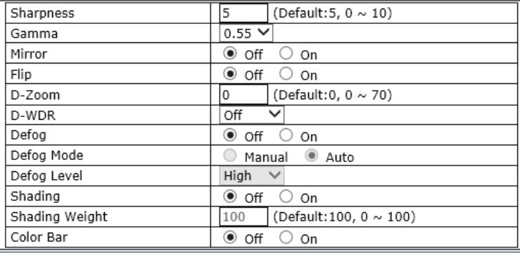 | |||||
■ Sharpness: Select the sharpness of image between 0 and 10.
Gamma:
■ Mirror: Flips the video images to the left or right.
■ Flip: Flip the video images up or down.
■ D-Zoom: Select whether to use digital zoom feature or not.
■ D-WDR: Select Digital Wide Dynamic Rage level to use D-WDR feature, or disable it.
■ Defog: Through the defogging function, camera can automatically recognize fog concentration of the image, defog, self-correct in hazy, rainy, flue gas and other inclement weather to get a clear image.
■ Defog Mode: The camera will automatically correct image according to the defogging level set by the user.
- Defog Level: The camera will adjust the definition of the image according to user's preferences through the defogging level.
■ Shading: Corrects dark areas of the image.
■ Shading Weight: Select the shading weight between 0 and 100.
■ Color Bar: Display color bar on the screen.
5.1.2 Primary Stream / Secondary Stream / Tertiary Stream
For the following camera models:
[Dual Stream Camera Models and FW3170 encoder]
Dual stream allows you to take advantage of two different streams from an IP camera. Primary stream can be high definition video for recording, while the Secondary stream can be a lower resolution for live display or supporting mobile. This allows for the NVR server or Clients to display more cameras while utilizing lower bandwidth and less CPU usage.
For the following camera models:
[Triple Stream Camera Models]
Triple stream has the advantage of dual-stream, and It is applicable to various networks, regardless of network bandwidth as high or low.
The Video Stream Configuration Menu will be displayed depending on the Compression Type and Rate Control Mode the user set as shown below.
H.264
| Camera Name | Primary Stream | ||
| H.264 Profile | ○ Base ○ Main ● High | ||
| Rate Control Mode | CBR Mode √ | ||
| Target Bitrate | 4.0 Mbps √ | ||
| GOP Structure | 16 | [1~64] | |
MJPEG
| Camera Name | Primary Stream | ||
| Image Quality | High | ▼ | |
- Camera Name: Enter the name of the Stream or channel up to 21 alphanumeric or up to 10 Unicode characters.
■ Rate Control Mode:
- VBR (Variable Bit Rate): VBR allows higher quality images regardless of the amount of bandwidth used.
○ Image Quality: Select the image quality
- Available Image Quality: Lowest, Low, Normal, High, Highest, Low Compression (Best Quality).
- CBR (Constant Bit Rate): CBR allows the user to fix the bit rate stream, regardless of scene activity, complexity and resolution.
- Bit Rate Control: Select the constant bit rate.
Available Bitrate: 32Kbps, 64Kbps, 128Kbps, 256Kbps, 512Kbps, 1.0Mbps, 1.5Mbps, 2.0Mbps, 3.0Mbps, 4.0Mbps, 5.0Mbps, 6.0Mbps, 8.0Mbps, 10Mbps, 12Mbps
- GOP Structure: The GOP value determines the sum total of P-frames and I-frames in a GOV. Setting the GOV-length to a high value saves considerably on bandwidth, but there may be noticeable image decay.
5.2 Motion Detection
Motion detection feature is enabled by default for all areas.
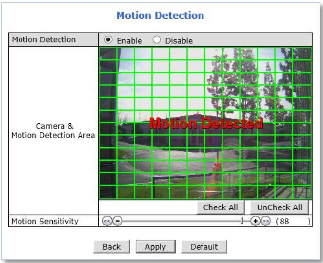
To disable the motion detection feature, Select Disable for the motion detection and click Apply.
To modify the motion detection area, please follow the steps below:
1) Click on any box in side scene to take out that area from motion detection.
- Green Box: Motion Detection Area
- Red Box: Excluded Area
2) Adjust Motion Sensitivity between -100 and 100. 100 is the most sensitive.
3) Click Apply.
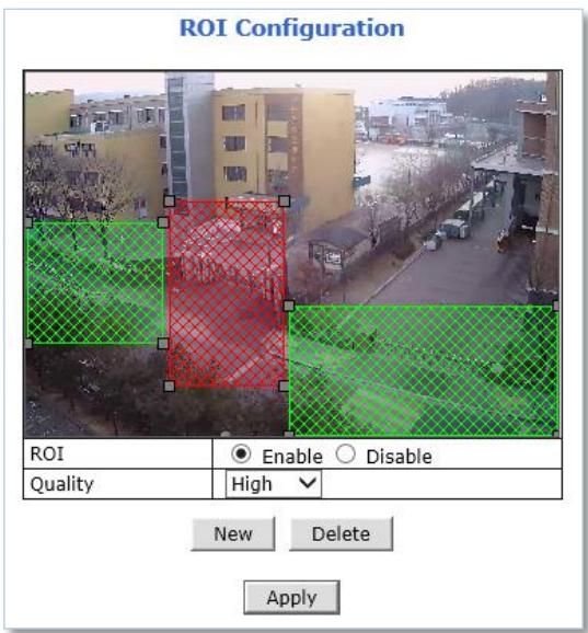
5.3 ROI (Region of Interest)
ROI feature allows the cameras to decrease non-ROI's image quality to save on maximum bandwidth and storage. These regions of interest will be smartly transmitted with better detail and image quality under identical bit rate streaming conditions.
To add a Region of Interest, please follow the steps below:
1) Enable ROI feature
2) Click New
3) Click Green box as shown below
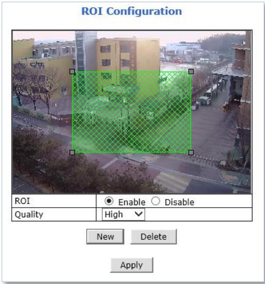
4) When selected green box turns red, set Region of Interest as follows:
- Resize- Click and hold any corner and drag to desired size
- Relocate- Click and hold anywhere inside the box and drag to desired location
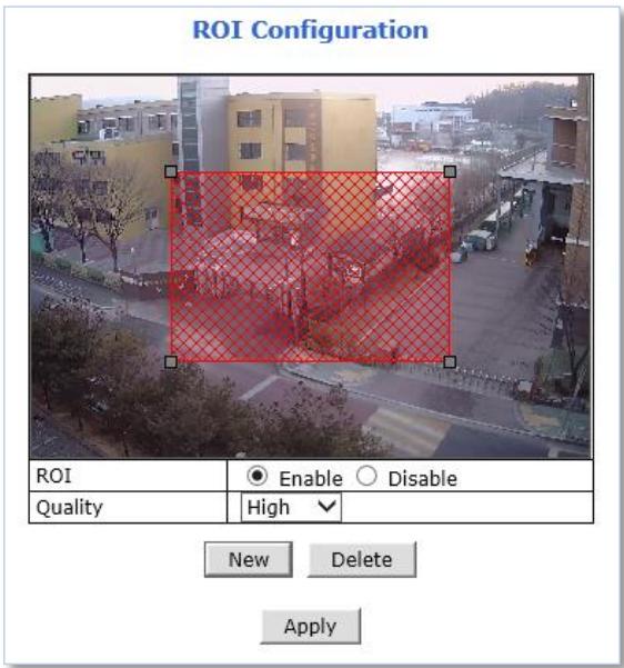
5) Select the Quality for region of interest
6) Click Apply
To delete a region of interest, select the region and click Delete followed by Apply.
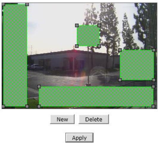
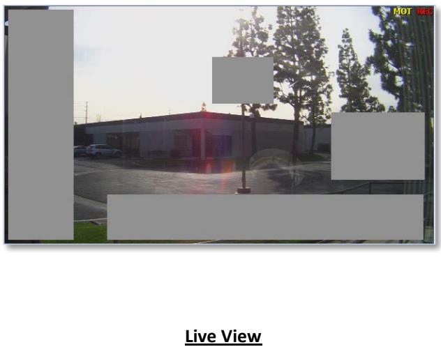
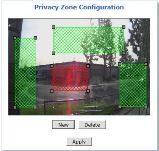
5.4 Privacy Zone
Up to 8 privacy zones can be setup by users if certain parts of the screen need to be unmonitored.
Privacy Zone Configuration
Privacy Zone Configuration Page
natural_image
Exterior view of a modern office building with trees and streetlights in the background (no signage)To add a privacy zone, please follow the steps below:
7) Click New
8) Click Green box as shown below
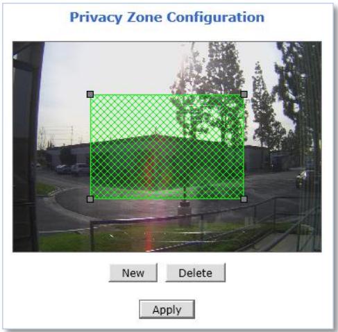
9) When selected green box turns red, set Privacy Zone as follows:
- Resize- Click and hold any corner and drag to desired size
- Relocate- Click and hold anywhere inside the box and drag to desired location
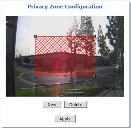
10) Click Apply
To delete a privacy zone, select the zone and click Delete followed by Apply.
5.5 Serial Ports
Any FlexWATCH ^® device that support serial ports has built-in COM and AUX port. These ports are used to communicate with external devices.
Generally, the COM port is used to console connection and AUX ports is used to PTZ connection.
5.5.1 Serial Input Mode
The FlexWATCH ^® device can be received data from the external device as an event in the Serial Input Mode. When event is occurred from the external device, the FlexWATCH ^® device can transmit received data with video images via email or FTP.
To configure Serial Input Mode, please follow the steps below:
Select Serial Port under Device Configuration menu on Web Admin Page as shown below.
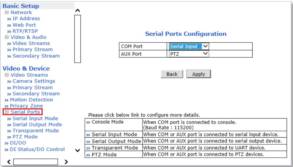
1) Select Serial Input for COM or AUX port and click Apply.
Note:
COM Port: Console / Serial Input / Serial Output / Transparent (by pass) AUX Port: PTZ / Serial Input / Serial Output / Transparent (by pass)
2) Click Reboot when reboot message appears as shown below.
3) When reboot is completed, login to the Web Admin Page again.
4) Go to Device Configuration -> Serial Ports -> Serial Input Mode.
Serial Input Mode Configuration
Select the serial input device supported by the system.
| Current Port | COM | |
| Current Protocol | RS232 | |
| Serial Input Model | Not Installed | √ |
Back
Apply
5) Select a Sensor Model from the Serial Input Model drop down menu.
6) Enter the sensor information if necessary.
7) Click Apply to finish.
Note: For other than listed sensor or input unit, please contact our technical support team. Integration process may require.
5.5.2 Serial Output Mode
Specific commands can be sent from the FlexWATCH ^® device to UART (Universal Asynchronous Receipt and Transmission) device via RS-232 or RS-485/422 in the Serial Output Mode.
The FlexWATCH ^® device can be control UART devices such as Multiplexer, Access control system, any devices using X10 or Z256 Protocol.
Serial Output Mode Configuration
| Current Port | None | |
| Line Mode | RS-232 √ | |
| Baud Rate | 38400 √ | |
| Data Bit | 8 √ bit | |
| Stop Bit | 1 √ bit | |
| Parity Bit | None √ | |
| Mode | ◎ By-Pass ○ X10 ○ Z256 | |
Back
Apply
To configure Serial Output Mode, select proper setting values and click Apply.
5.5.3 Transparent Mode
RS-485/422/232 data from the external device can be by passed to IP client or server through Ethernet in the transparent mode. IP Client/Server also allows controlling the external RS-485/422/232 device via FlexWATCH® device.
Transparent Mode Configuration
| Current Port | None | ||
| Line Mode | RS-485 | √ | |
| Baud Rate | 9600 | √ | |
| Data Bit | 8 | √ bit | |
| Stop Bit | 1 | √ bit | |
| Parity Bit | None | √ | |
| Network Protocol | UDP | √ | |
| Peer IP | 127.0.0.1 | ||
| Network Port | 32000 | (Default:32000, 10000 ~ 65535) | |
| Data Start Pattern | ☐ | ||
| Data Size | 0 | ||
Back
Apply
To configure Transparent Mode, please follow the steps below:
1) Select connection type from the drop down menu of Line Mode.
2) Select connection speed from the drop down menu of Baud Rate.
3) Select Data and Stop Bit size.
4) Select Parity Bit type.
5) Select Network Protocol.
6) Enter Server/Client IP in the Peer IP field.
7) Enter Data Start Pattern if necessary.
8) Enter Data Size per packet if necessary.
9) Click Apply to finish.
5.5.4 PTZ Mode [for FW3170 / FW1173 / FW1175 / FW1176 Models only]
PTZ cameras or receivers can be controlled via AUX port in PTZ mode.
PTZ Mode Configuration
| Current Port | AUX | |
| Dummy Data | ○ On ● Off | |
| Current Protocol | RS485 √ | |
| Current Baudrate | 9600 √ | |
| PTZ Model | Built-in PTZ √ | |
| Base Address | PTZ Install Flag | |
| Ch 1 | Ch 2 | |
| 0 (0~255) | ☑ | ☐ |
Back Apply
To configure Serial Input Mode, please follow the steps below:
1) Select connection type from the Current Protocol drop down menu.
2) Select connection speed from the Current Baud rate drop down menu.
3) Select PTZ protocol from the PTZ Model drop down menu.
4) Enter Base Address to assign PTZ ID to the camera channels
ID number for each channel will be assigned by sum of base address and channel number.
5) Check the desired channel number(s) to connect with PTZ
6) Click Apply
Note: Protocol (PTZ Model), Baud rate, ID number should be matched on both PTZ and FlexWATCH ^® device.
FlexWATCH® Supports 58 PTZ Protocols which are follows (firmware version 4.28):
| Pelco-D-AUX : Spectra Dome | FINE : CPR-1600I |
| Pelco-P-AUX : Spectra Dome | Dongyang : DY-xxxx |
| Seyeon Tech : SRX-500/SPT-102 | Bosch : Auto Dome |
| Seyeon Tech : FSD-230/270 | Sungjin : SJ2000/SJ3000RX |
| Seyeon Tech : FSD-301 | Honeywell : HRX-2000 |
| ELMO : ELDOME | Inter-M : VRX2201 |
| SANTEC : Santec Dome | LG : Speed Dome |
| Honeywell : HSDN-230/251(H) | LILLIN : PIH7000 |
| Honeywell : HSDN-230/251(P) | Yujin : YRX-5000S |
| SAMSUNG : SCC641/643A | INTPLUS : Pelco-P PTZ1 |
| SAMSUNG : SCC641/643A(RS422) | VICON : V-1311RB-600 |
| SAMSUNG : MRX-1000 | Pelco-D : SK-D106 |
| VICON : V-1311RB | Pelco-D : Yujin |
| VICON : Surveyor-1000/2000 | Pelco-D :-AUX : HUVIRON |
| SAMSUNG Techwin : SPD1600 | Pelco-P-AUX : ONE KING |
| SAMSUNG Techwin : SRX-100B | Pelco-D-AUX : Probe |
| SAMSUNG Techwin : SRX-100-R | Honeywell : HSDN-P 251(H) |
| American Dynamics : DELTA DOME | Dong Yang : DMax Series |
| KALATEL : CYBER DOME(KTA-xxxx) | Pelco-D-AUX : Neo IR Dome |
| Panasonic : WV-CS854 | RVT : EX Series |
| SONY : EVI-D30 | Panasonic : WV-CW864A |
| CANON : VC-C4 | E-ronix : Pelco-D |
| RNK : RNK-DOME | SONY : VISCA |
| ERNITEC : BDR-510 | Pelco-D-WW-MD : Spectra Dome |
| Inter-M : VSD-640/625L | Sungjin : SJ2819RX3 |
| Seyeon Tesh : SMP001 | Convex : CXD Series |
| GPI360 : VISCA | Pelco-D-AUX : Convex |
| Pelco-D-AUX : YOUGUAN CCTV | Pelco-D-AUX : HANKOOK CTEC |
| Pelco-D-Wonwoo IR : Spectra Dome | Pelco-D-AUX : Cynix |
5.6 DI (Sensor Input) / DO (Alarm Output)
Depending on the number of DI ports supported, the numbers of ports that can be set are different as shown below, but the setting method is same for all models.
Example:
DI/DO 1 Port Models
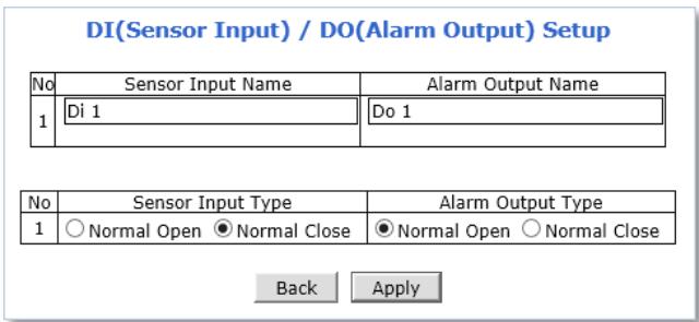
To setup DI/DO port, please follow the steps below:
1) Enter Sensor Input Name and/or Alarm Output Name to the desired DI port number.
(Up to 31 alphanumeric or 15 Unicode characters can be used for server name)
2) Select Sensor Input Type and/or Alarm Output Type.
■ Normal Open Type: Normal is OPEN, and goes CLOSED when triggered by an event.
■ Normal Close Type: Normal is CLOSED, and goes OPEN when triggered by an event.
3) Click Apply.
Note: Make sure the type of the sensor and use it correctly to the type. If a Sensor Input is not used, it must be set to Normal Open Type to avoid a false input.
5.7 DI Status / DO Control
Depending on the number of DI ports supported, the numbers of ports that can be controlled are different as shown below, but the controlling method is same for all models.
Example:
DI/DO 1 Port Models
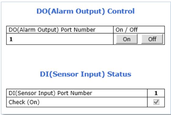
External device that connected with the DO (Alarm Output) port can be tested as picture above.
- Click On to operate the external device connected with DO port.
- Click Off to stop operating the external device.
DI (Sensor Input) Status shows Sensor Status as shown picture above.
The check mark in the box indicates that the DI (Sensor Input) is activated. If there is no check mark in the box, means the DI is not activated.
6. Recording
Depending on FlexWATCH devices, HDD or SD card can be installed for video recording and playback. Recording conditions and storage related setting are available in this menu section.
Note: The maximum number of installable hard disk and maximum capacity available may vary depending on the NVR models.
6.1 Disk Setting
Recording storage related settings and information can be found here.
Note: A newly installed HDD or SD card must be initialized or formatted in the Disk Setting menu. All the HDD or SD card data will be deleted after the disk initializing or formatting.
6.1.1 Disk Status & Format
Depending on current disk status, the Disk Status & Format page will be displayed as follows:
- No SD: Micro SD card is not installed or recognized. Make sure that the Micro SD card is installed properly.
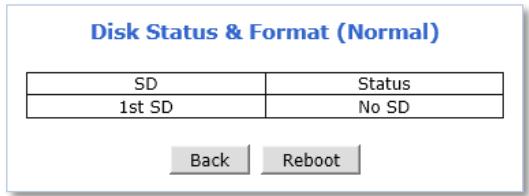
No SD
■ Unformatted: Micro SD card is not formatted. A newly installed Micro SD card must be formatted.
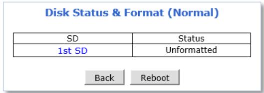
Unformatted
- Formatted: Micro SD card is ready for recording or under recording now.
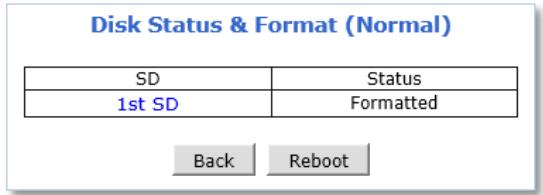
Formatted
To initialize or format the Micro SD card, please follow the steps below:
1) Click desired Micro SD card to format
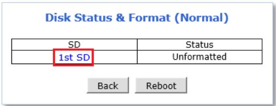
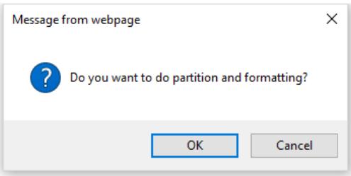
2) Click Partition and Format
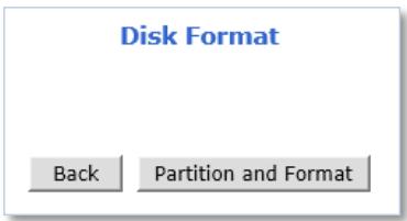
3) Click OK to continue when confirmation window appears
Warning: Do not leave HDD format Status page during the formatting. If an abnormal termination is happened during the formatting process, it is possible for the hard drive to be defected. Make sure to complete the process properly.
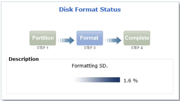
flowchart
graph LR
    A["Partition\nSTEP 1"] --> B["Format\nSTEP 3"]
    B --> C["Complete\nSTEP 4"]
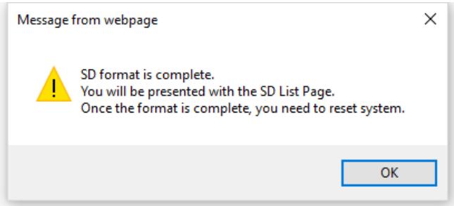
4) When done, click OK to finish formatting
5) Check the current status "Formatted" as shown below
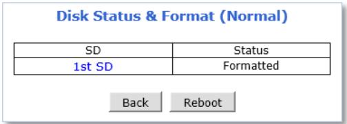
6) Click Reboot
Note: If the current status is not displaying “Formatted”, it is possible for the Micro SD card to be defected. Make sure to complete the process properly.
6.1.2 Disk Information
Detailed information of the installed Micro SD card can be found in Disk Information page as shown below.
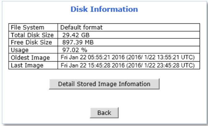
■ File System: Display current file system
■ Total Disk Size: Display the capacity of the storage
■ Free Disk Size: Displays the remaining capacity of the storage
■ Usage: Display the storage usage
- Oldest Image: Shows the creation time of the oldest image files stored in the storage
- Last Image: Shows the creation time of the latest image files stored in the storage
6.1.3 Disk Circulation
The installed Micro SD card can be set whether or not to overwrite.
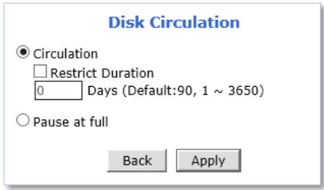
■ Circulation: Overwrites old recorded data when the installed Micro SD card is full.
- Restriction Duration: Record data only in the configured period and delete after the period.
- Pause at full: Stops recording when the storage is full, and display STOP in the status as shown below.
6.1.4 Disk Status Report
Current status of the installed Micro SD card can be reported by email periodically or in the set conditions.
To setup the storage statures Report, please follow the steps below:
1) Set Report conditions as explained below
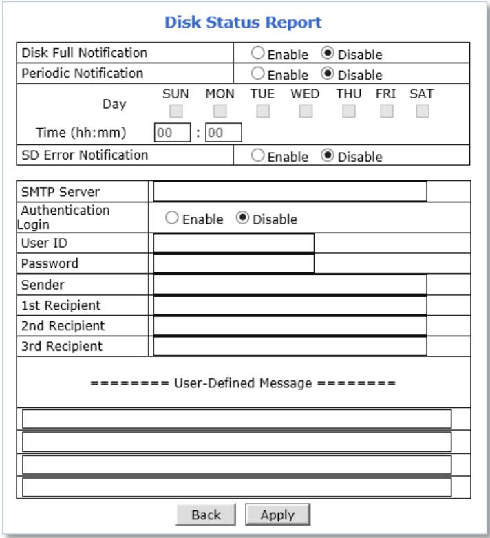
- Disk Full Notification: when the Micro SD card is full, notify by email.
■ Periodic Notification: at a specified time, notify the Micro SD card status by email. - Disk Error Notification: when the disk error occurred, notify by email.
2) Enter your SMTP server address
3) If your SMTP server requires user authentication, select Enable for Authentication Login and enter the user ID and Password for your SMTP server
4) Enter your email address in Sender field, which will show the message was sent from the FlexWATCH® device as a notification
5) Enter the email addresses of recipients up to 3 addresses
6) In the User-Defined Message box, you may enter any messages that will include with notification email
7) Click Apply
6.2 Recording Setting
Depending on number of video channels or streams supported, the Recording Setting page will be displayed as follows:
Note: The procedure of recording setting is same for all streams or channels.
Recording Setting
Please click camera name to configure Recording condition.
| Recording Setting | ||||||
| VS Module ID(IP Devices) | Name | IP Address | Port | Vendor | Camera Name | REC.Config. |
| 0 | Built-in Module 0 | Built-in Module 0 | 0 | Built-in Device | Primary Stream | Disable |
| 0 | Built-in Module 0 | Built-in Module 0 | 0 | Built-in Device | Secondary Stream | Disable |

| Status | Record Ready | Stop |
Example:
Dual Streams Camera Models.
Recording Setting
Click a camera name to configure the recording conditions.
| Recording Setting | ||||||
| VS Module ID (IP Devices) | Name | IP Address | Port | Vendor | Camera Name | REC. Config. |
| 0 | Built-in Module 0 | Built-in Module 0 | 0 | Built-in Device | Primary Stream | Disable |
| 0 | Built-in Module 0 | Built-in Module 0 | 0 | Built-in Device | Secondary Stream | Disable |
| 0 | Built-in Module 0 | Built-in Module 0 | 0 | Built-in Device | Tertiary Stream | Disable |

| Status | Recording | Stop |
Notice : To start recording with the new configurations, click the "Apply" button. Otherwise, recording with the new configurations will not start even if the recording configurations are correctly set up.
Example:
Triple Streams Camera Models.
To configure the recording, please follow the steps below:
1) Click on the Camera Name of the desired channel to record
Recording Setting
Click a camera name to configure the recording conditions.
| Recording Setting | ||||||
| VS Module ID(IP Devices) | Name | IP Address | Port | Vendor | Camera Name | REC.Config. |
| 0 | Built-in Module 0 | Built-in Module 0 | 0 | Built-in Device | Primary Stream | Disable |
| 0 | Built-in Module 0 | Built-in Module 0 | 0 | Built-in Device | Secondary Stream | Disable |
2) Click the first Not Used Condition
Recording Setting (VS Module ID 0, Camera 1)
» Display current recording settings Click a link below to configure the recording conditions.
| Condition 1 [Not Used] | ||||||||||||||||||||||||
| Condition 2 [Not Used] | ||||||||||||||||||||||||
| Condition 3 [Not Used] | ||||||||||||||||||||||||
| Condition 4 [Not Used] | ||||||||||||||||||||||||
| 01 | 02 | 03 | 04 | 05 | 06 | 07 | 08 | 09 | 10 | 11 | 12 | 13 | 14 | 15 | 16 | 17 | 18 | 19 | 20 | 21 | 22 | 23 | 24 | |
| Sun | ||||||||||||||||||||||||
| Mon | ||||||||||||||||||||||||
| Tue | ||||||||||||||||||||||||
| Wed | ||||||||||||||||||||||||
| Thu | ||||||||||||||||||||||||
| Fri | ||||||||||||||||||||||||
| Sat | ||||||||||||||||||||||||
| 1 | 2 | 3 | 4 | 1 | 2 | 3 | 4 | |||||||||||||||||
| Alarm Sensor | □ | □ | □ | □ | Camera Connected | □ | □ | □ | □ | |||||||||||||||
| Motion Detection | □ | □ | □ | □ | Camera Disconnected | □ | □ | □ | □ | |||||||||||||||
| Common Alarm Sensor | □ | □ | □ | □ | External Input Data | □ | ||||||||||||||||||
| Always | Schedule | Schedule and Event |
| Recording Service | ● Enable ○ Disable | ||
| Server Module ID | 0 | Camera Number | 1 |
| Camera Name | Primary Stream | ||
| Pre-Alarm Images | 0 √ | Post-Alarm Images | 0 √ |
| Pre-Alarm Speed | fastest √ | Post-Alarm Speed | fastest √ |

Note: Up to 4 conditions can be set.
If multiple conditions are set, recording starts when any one or more conditions meet. (Logical OR)
3) When the condition page appears, Enable the selected Condition
Enable
Disable
4) Select Mode
| Select Mode | ○ Always |
| ○ Schedule Only | |
| ● Event Only | |
| ○ Schedule and Event |
■ Always: [Please do not use this mode for Email notification.]
■ Schedule Only: [Please do not use this mode for Email notification.]
■ Event Only: Send email when selected event occurred
■ Schedule and Event: Send email when selected event occurs in specified time
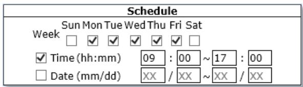
5) Specify the Recording Schedule if necessary
6) Select Event Type
| Event | ||||
| 1 | 2 | 3 | 4 | |
| Alarm Sensor | ||||
| Motion Detection | ✓ | |||
| External Input Data | ||||
| Camera Connected | ✓ | |||
| Camera Disconnected | ||||
| Boot Finished | Enable | |||
| Serial Input | Activated | |||
■ Event will be triggered by the followings:
• Alarm Sensor (Alarm Input)
- Motion Detection
• External Input Data such as POS.
- Camera Connection
- Connected
- Disconnected
- Boot Finished
- Serial Input
7) Click Save

8) When the following page appears, check the summary in the purple box as shown below.
![Recording Setting (VS Module ID 0, Camera 1) Display current recording settings Click a link below to configure the recording conditions. Condition 1 [MON,TUE,WED,THU,FRI,][09:00~17:00] [M1,M2,] Condition 2 [SUN,SAT,] Condition 3 [Not Used] Condition 4 [Not Used] 01 02 03 04 05 06 07 08 09 10 11 12 13 14 15 16 17 18 19 20 21 22 23 24 Sun Mon Tue Wed Thu Fri Sat 1 2 3 4 1 2 3 4 Alarm Sensor □ □ □ □ Camera Connected □ □ □ □ Motion Detection ✓ ✓ □ □ Camera Disconnected □ □ □ □ Common Alarm Sensor □ □ □ □ External Input Data Always Schedule Schedule and Event Recording Service Enable Disable Server Module ID 0 Camera Number 1 Camera Name Primary Stream Pre-Alarm Images 0 ✓ Post-Alarm Images 0 ✓ Pre-Alarm Speed fastest ✓ Post-Alarm Speed fastest ✓ Back Save](/content/2019/12/21144/images/c9b34d8f2db7b176b2293cff634746d54b7bead2948c524035a999f1436d5cf8.jpg)
9) Enable for the Recording Service
10) Set Pre/Post Alarm Images, if necessary
Note: MJPEG Compression Type is required for Pre/Post Alarm Image features.
11) Click Save
12) When the following page appears, make sure the recording configuration is enabled as red box below
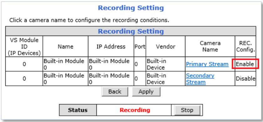
13) Go to step 1) if recording configuration is needed for other channels
14) Click Apply when the recording configuration is completed
15) Click Record if recording status is "Stop" as shown below
| Status | Stop | Record |
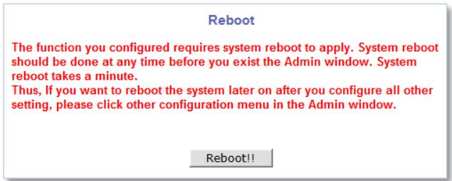
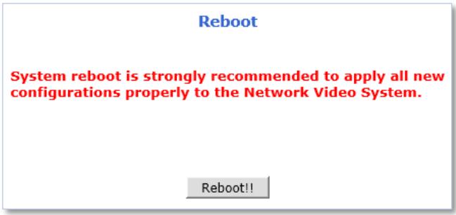
16) Reboot the NVR as shown below
Reboot
System reboot is strongly recommended to apply all new configurations properly to the Network Video System.
Reboot!!
6.3 Recording Profile
Recording Profile shows current recording settings for all channels as shown below.
| Recording Profile | ||||||||||||||
| Server | Camera | REC.Config. | Status | Start Date | End Date | Start Time | End Time | Week | ||||||
| Month | Day | Month | Day | Hour | Min | Hour | Min | Sun | Mon | Tue | ||||
| Built-in Module 0(Built-in Module 0) | Primary Stream | Enable | XX | XX | XX | XX | 9 | 0 | 17 | 0 | ||||
| XX | XX | XX | XX | XX | XX | XX | XX | |||||||
| XX | XX | XX | XX | XX | XX | XX | XX | |||||||
| XX | XX | XX | XX | XX | XX | XX | XX | |||||||
| XX | XX | XX | XX | XX | XX | XX | XX | |||||||
| Secondary Stream | Disable | XX | XX | XX | XX | XX | XX | XX | XX | |||||
| XX | XX | XX | XX | XX | XX | XX | XX | |||||||
| XX | XX | XX | XX | XX | XX | XX | XX | |||||||
| XX | XX | XX | XX | XX | XX | XX | XX | |||||||
6.4 Clear Setting
Recording configuration can be deleted or reset for the all channels in this menu.
To clear recording configuration:
1) Click Clear to clear or delete recording configuration
Clear Setting
- Click 'Clear' to completely delete all the recording setting you have made in the system and start new configuration.
- Please be more careful not to lose your current recording setting.
Back
Clear
2) Click OK when confirmation message appears as shown below.
6.5 Delete Recorded Data
Recorded data in the Micro SD card can be deleted in this menu.
To deleted recorded data in the Micro SD card:
1) Select the storage to delete recorded data
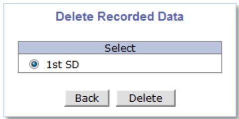
2) Click Delete to delete recording data
3) Click OK when confirmation message appears as shown below

7. Network
All network related settings can be found under the Network Menu.
| Video & DeviceRecordingNetwork IP Address Web Port RTP/RTSP Bandwidth Network Status Network Status Notify DDNS UPnP SNMP HTTPS Zeroconf IP FilteringSystemAdvancedUtilities | NetworkThis category shows the detailed method for network system. | |
| IP Address | Configuration of Network(IP,Netmask,DNS). | |
| Web Port | Modification of HTTP and other application network port numbers. | |
| RTP/RTSP | Configuration of RTP/RTSP. | |
| Bandwidth | Configuration of bandwidth control. | |
| Network Status | View of Network Status. | |
| Network Status Notify | It sends IP address by e-mail when IP address is allocated by DHCP(or PPPoE). | |
| DDNS | Configuration of dynamic IP registration of Network Video System. | |
| UPnP | Configuration of Port Forwarding & UPnP(Universal Plug and Play). | |
| SNMP | Configuration of SNMP. | |
| HTTPS | Configuration of HTTPS. | |
| Zeroconf | Configuration of Zeroconf. | |
| IP Filtering | Configuration of ip filtering. | |
7.1 IP Address
7.1.1 Static IP
For a Static IP, select Static IP and Enter IP information for the device such as IP Address, Subnet Mask (NetMask), Default Gateway (GateWay), DNS 1, DNS 2(Optional) and click Apply to save settings.
| IP Address | 10.0.0.15 | |
| NetMask | 255.0.0.0 | |
| GateWay | 10.0.0.1 | |
| DNS 1 | 10.0.0.1 | |
| DNS 2 | 168.126.63.2 |
After selecting Apply, program will ask to close web browser for updates, which will take more than 20 seconds to reboot the device. If Back button is clicked, all values will be discarded. If Refresh button is clicked, the program will load previous values.
7.1.1.1 IPv6
The FlexWATCH ^® devices support IP version 6 (IPv6).
To use IP version 6, enable the IPv6 service first, and then enter IPv6 IP address and Gateway.
| Service | ○ Enable ● Disable | |
| IP Address | Ex) fec0:1234::abcd:abcd/64 | |
| GateWay | Ex) fec0:1234::abcd:1 | |
| IPv6 Link-Local | fe80::230:6fff:fe84:4d01/64 | |
7.1.1.2 Wireless (Wi-Fi)
Wireless setting menu appears at the bottom of network configuration setting page as shown below when the Wi-Fi USB Adapter is attached to the Wi-Fi support camera
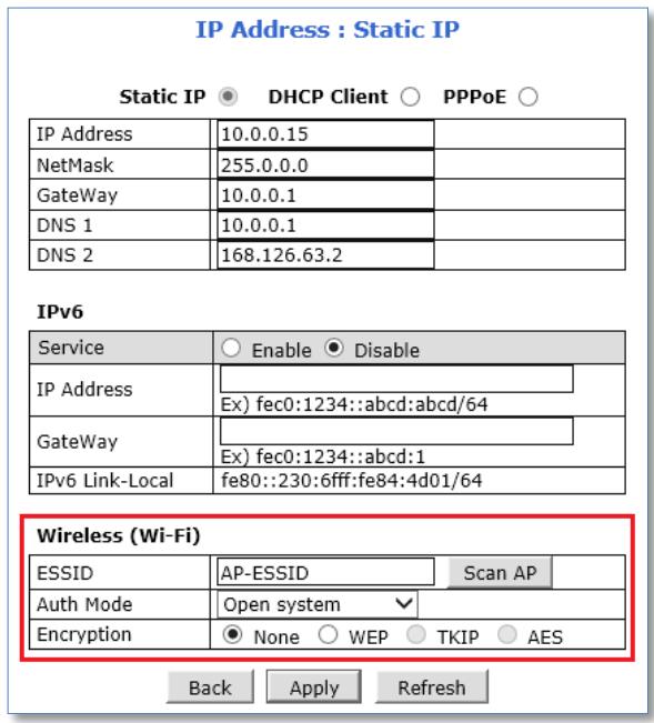
To use Wi-Fi connection, Enter ESSID(SSID) manually or scan and select your Wi-Fi network and then select authentication mode for the wireless network. Wi-Fi encryption method must be correctly applied to connect to the SSID.
Note: If both wired and wireless network are connected, wired network connection will take priority. After the wireless network settings through wired connection, unplug the network cable to connect Wi-Fi. It will take few minutes for initialization.
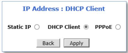
7.1.2 DHCP Client
A Router providing an automatic DHCP Lease is required in the network for this option.
To use DHCP Client, select DHCP Client and click Apply to save. After Apply, program will ask to close web browser for updates, which will take more than 20 seconds to reboot the device.
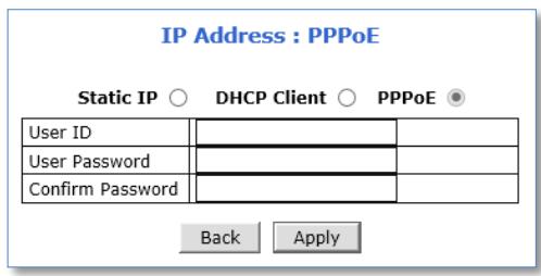
7.1.3 PPPoE
The FlexWATCH ^® devices can be connected directly to a PPPoE modem provided by the internet service provider usually with Internet Service Providers using DSL Login. To use PPPoE connection, enter User ID and Password for your PPPoE account and click Apply.
7.2 Web Port
Network or HTTP port is used to access FlexWATCH ^® devices and data exchange between the FlexWATCH ^® device (server) and clients if required. The port can be changed any number from 80 to 65535. The default value is 80.
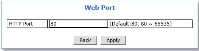
Note: If the HTTP port number is changed to a different value than default (80), make sure the new HTTP port number goes together with IP address of the FlexWATCH ^® devices. For example, when an IP address of FlexWATCH ^® devices is 192.168.1.100 and the HTTP port is changed 8080, you will have to enter http://192.168.1.100:8080 at the address bar on your web browser to connect to the device.
7.3 RTP / RTSP
RTSP (Real-Time Streaming Protocol) is a protocol to transfer video and audio streams over the network and it allows compatibility with other manufactures' VMS/NVR software or video streaming software such as VLC player, Quick Time player.
For using the FlexWATCH ^® device as an ONVIF device, RTSP service must be enabled.
To use RTP/RTSP protocol,
RTP/RTSP Setup
| Service | ● Enable ○ Disable | ||
| RTSP Port | 554 | (Default:554, 554 ~ 65534) | |
| RTP Start Port | 5000 | (Default:5000, 2048 ~ 65534) | |
| Packet Size | 1 | (Default:1, 1 ~ 12) | |
| Camera 1 | Multicast Address | 0.0.0.0 | Disable:0.0.0.0(225.0.0.0 ~ 239.255.255.255) |
| Multicast Port | 0 | (Disable:0, 2048 ~ 65534) | |
| Camera 2 | Multicast Address | 0.0.0.0 | Disable:0.0.0.0(225.0.0.0 ~ 239.255.255.255) |
| Multicast Port | 0 | (Disable:0, 2048 ~ 65534) | |
Back
Apply
1) Enable RTP/RTSP service
2) Enter desired RTSP and RTP Start Port
3) Enter Packet Size (Kilobyte)
4) Click Apply
7.3.1 RTSP URL
FlexWATCH ^® device support two types of RTSP URL which are Unicast and Multicast.
■ Unicast: rtsp://(Network Video Server IP Address)/cam0_0 [ cam(0: *VS Module number)_(0:**Channel/Stream number) ]
■ Multicast : rtsp://(Network Video Server IP Address)/mcam0_0 [mcam(0: *VS Module number)_(0:**Channel/Stream number)]
Usage
*VS Module number
Use "0" for:
- Dual Stream Camera Models.
- 1/4 Channel Server (Video Server, NVR Server) Models.
Use "1" for:
- Channel #5\~8 on 8Channel Server Models.
**Channel/Stream number
Use "0" for:
- Primary Stream on Dual Stream Camera Models.
- Channel #1 on 1/4/8 Channel Server Models.
- Channel #5 on 8 Channel Server Models. (VS module ID should be 1) Use "1" for:
- Secondary Stream on Dual Stream Camera Models.
- Channel #2 on 1/4/8 Channel Server Models.
- Channel #6 on 8 Channel Server Models. (VS module ID should be 1) Use "2" for:
- Channel #3 on 4/8 Channel Server Models
- Channel #7 on 8 Channel Server Models. (VS module ID should be 1) Use "3" for:
- Channel #4 on 4/8 Channel Server Models
- Channel #8 on 8 Channel Server Models. (VS module ID should be 1)
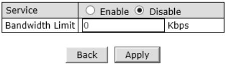
7.4 Bandwidth
Bandwidth control is for limiting the maximum network traffic.
If the Bandwidth Control Configuration is enabled, maximum data size transferred from the FlexWATCH® device won't exceed bandwidth limits set by users. If transferred data is exceeded, part of the data will be randomly lost. If multiple users try to access a FlexWATCH® Device when bandwidth control is enabled, users connected to the FlexWATCH® device will share network bandwidth limit.
Bandwidth Configuration
Note: This bandwidth control feature works well in M-JPEG video transmission. But, for H.264, dropping data packets may cause low quality of video, so it is recommended to utilize CBR and frame rate control instead of bandwidth control for H.264 video Network Bandwidth control is managed by FlexWATCH® device and it drops any data packets when data packets exceeds bandwidth limit, thus you may experience slow connection when this feature is enabled.
7.5 View Network Status
Selecting Network Status will provide details of the FlexWATCH ^® devices.
If wireless connection is set, wireless connection status will be displayed at the bottom.
Network Status
Common Status
| Gateway | 10.0.0.1 |
| Gateway Device | eth0 |
| DNS1 | 10.0.0.1 |
| DNS2 | 168.126.63.2 |
LAN Status
| IP Address | 10.0.0.15 |
| Netmask | 255.0.0.0 |
| MAC Address | 00:30:6F:84:4D:01 |
| IPv6 Link-Local Address | fe80::230:6fff:fe84:4d01/64 |
PPPoE Status
| Connection Status | Link is down |
| IP Address | |
| Netmask |
Zeroconf Status
| IP Address | 169.254.12.27 |
Back
Refresh
7.6 Network Status Notify
Network Status can be notified to the administrator by email when
- IP address of the FlexWATCH ^ device has been changed by DHCP server
- FlexWATCH® device has been connected to a PPPoE Server
Note: This feature is valid only for DHCP or PPPoE connection.
To configure the Network Status Notify feature, please follow the steps below:
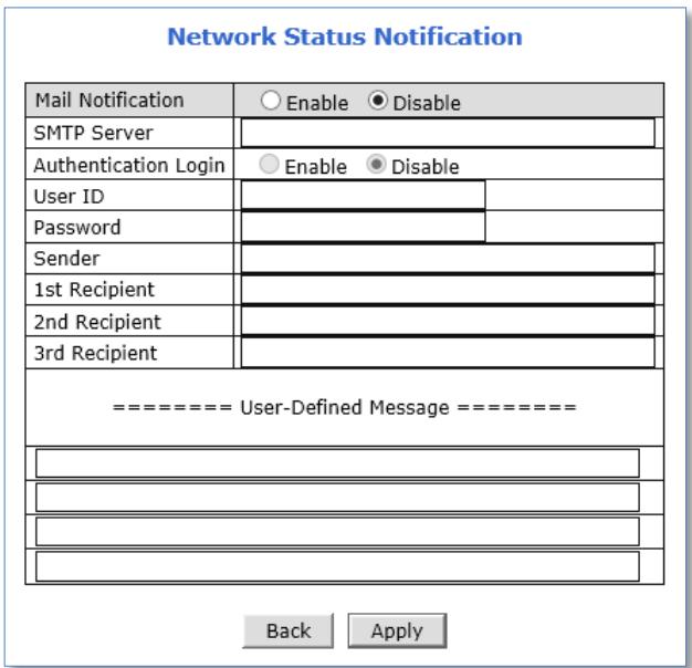
1) Select Enable to use Mail Notification feature
2) Enter the SMTP server address
3) If the user authentication is required by SMTP server, select Enable for Authentication Login and enter the user ID and Password for the SMTP server
4) Enter an email address of the Sender in Sender field, which will be appeared as the sender in notification email
5) Enter an email address of recipient (up to 3 email addresses are available)
6) In the User-Defined Message box, please enter any messages that will be included within the notification email
7) Click Apply
7.7 DDNS
IP-CCTV DNS™ (As known as DDNS service) provides a domain name to connect to a remote site. DDNS is used when the Internet Service Provider is using a Dynamic IP address that is always changing every two to three months.
To activate IP-CCTV DNS™ service, please follow the steps below:
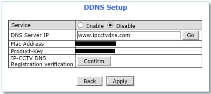
1) Select Enable to use IP-CCTV DNS™ service
2) Click Go to go to IP-CCTV DNS™ web site or go to www.ipcctvdns.com directly through the web browser
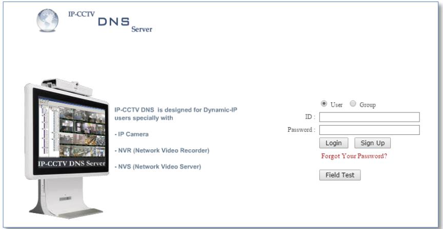
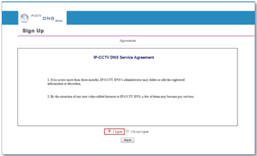
3) Click Sign Up to create an account if you do not have one
If you have one, proceed from the step 6
4) Select "I Agree" and click Next as shown below
5) Enter the information requested such as ID, Password and Name, and then click Apply to finish
![IP-CCTV DNS Server Sign Up Membership ID [E-Mail] * Password * Confirm Password * Name * Company Telephone * Mobile Phone Address Country * Select Country Description check Apply Reset](/content/2019/12/21144/images/e05e662a5b2b00de391d3834004aee28f05330ea773c45914edb634d04d97a28.jpg)
6) Login to the IP-CCTV DNS™ with the ID and password
7) Click on Product Registration on Top Menu as shown below
8) Enter the information requested (Camera Name, MAC Address, Product Key) and Click Apply as shown below
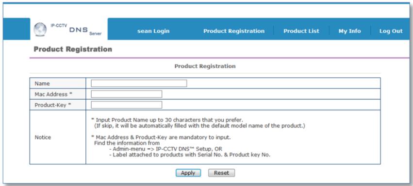
Note: Mac Address and Product Key will be available at the sticker on the FlexWATCH ^® device or on the IP-CCTV DNS ^™ setting page under Network Configuration Menu of the Web Admin Page.
9) Click OK to confirm that the device has been registered successfully as shown below
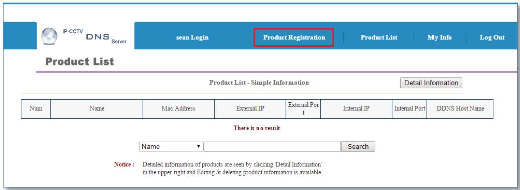
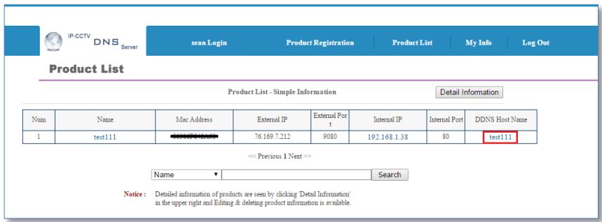
10) Click Product List as shown below
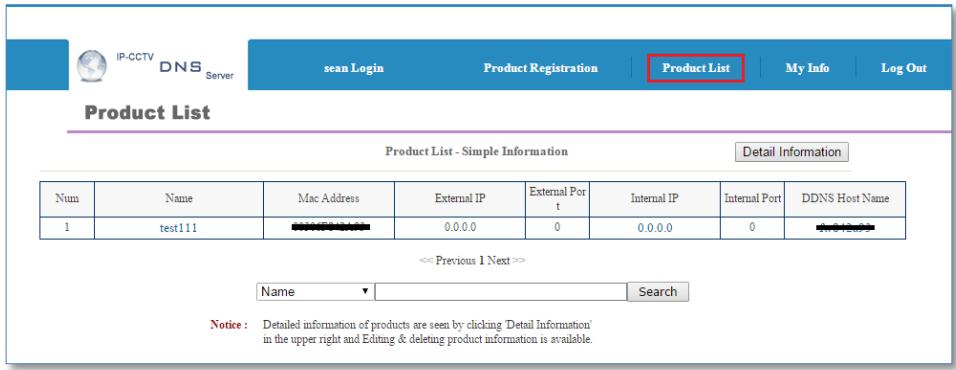
11) Reboot the FlexWATCH ^® device at Reboot page under Utilities menu of the Web Admin Page
12) When the device reboot is complete, return to the Product List page on your browser and refresh the Product List page until your current public IP address is displayed as shown below
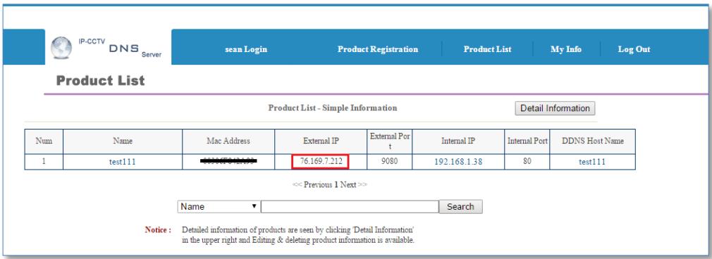
Note: “[DDNS Host Name].ipcctvdns.com” will be used as your domain name or URL for remote access. You may change your DDNS Hose Name.
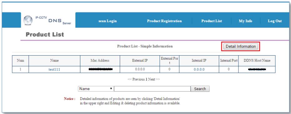
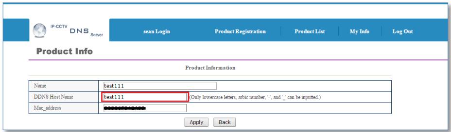
To change the DDNS Host Name, please follow the steps below:
1) Click Detail Information as shown below
2) Click Edit as shown below
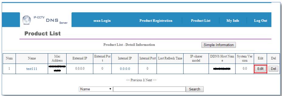
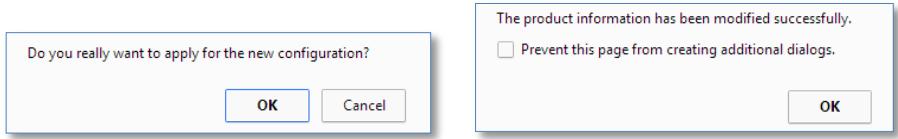
3) Enter Desired Host Name and click Apply
4) Click Ok when the following messages appear
5) Check your changed DDNS Host Name as shown below
7.8 UPnP
7.8.1 UPnP Port Forwarding
UPnP port forwarding will allow an IP device to communicate with an UPnP compatible network router for simplified local network device access as well as remote access via the Internet. In order to allow for UPnP port forwarding, UPnP supported router is required.
To do UPnP port forwarding, please follow the steps below:
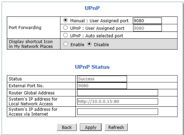
1) Select one and follow the directions for each options:
- Manual (User Assigned Port): Enter the port number that you set in the router and click Apply.
Note: Port forwarding is required for the Manual option.
- UPnP (User Assigned Port): Enter desired port number and click Apply
- UPnp (Auto Selected Port): Click Apply
2) When the UPNP port forwarding process is done successfully, "Success" message will be appeared as shown below
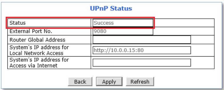
If error message appears, check whether the router's UPnP support and ensure that UPNP is enabled
7.8.2 Display Shortcut Icon in My Network Place
Display shortcut Icon in My Network Places option will allow you to access the FlexWATCH® device via Windows Explorer as shown below.
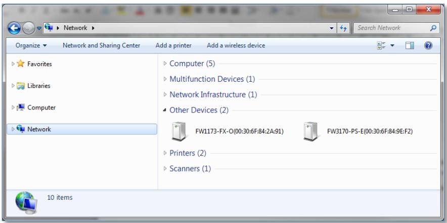
Note: For using this feature, Windows™ XP with Service Pack 2 (SP2) or higher version of Windows™ is required.
7.9 SNMP
SNMP (Simple Network Management Protocol) allows network management operators to use standard SNMP (SNMP) tools to monitor the status of FlexWATCH ^® devices.
Note: SMTP Version 1 and 2 are supported based on MIB-2.
When selecting SNMP under Network Configuration menu, SNMP setting page will be displayed as shown below.
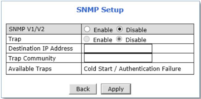
To use SNMP,
1) Enable SNMP V1/V2 protocol.
2) Enable for SNMP TRAP service if necessary.
3) Enter the IP address of the server to receive SNMP Trap messages in Destination IP Address field.
4) Enter the Trap Community.
5) Click Apply
7.10 HTTPS
HTTPS (Hyper Text Transfer Protocol Secure) is identical to HTTP but provides enhanced security. The data transferred is encrypted using Secure Socket Layer (SSL) or Transport Layer Security (TLS). This security method applies encryption to the data itself.
To use HTTPS connection, please follow the steps below:
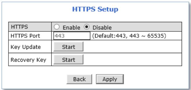
1) Enable HTTPS feature.
2) Change HTTPS port if necessary.
3) Click Apply.
Note:
HTTPS connection is made only when your login to the Web Admin Page.
You may enter a key issued by a certificate authority.
Entered Key can be reset with the Recovery Key Start button if necessary.
Certificate Error message may be displayed if the key is not certified or not valid as shown below.
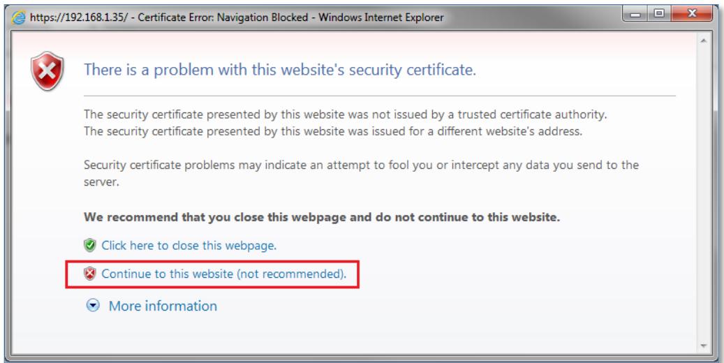
Click Continue to this website if the above message appears.
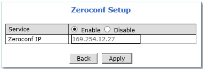
7.11 Zeroconf
Zero-configuration networking (zeroconf) is a set of technologies that automatically creates a usable computer network based on the Internet Protocol Suite (TCP/IP) when computers or network peripherals are interconnected. It does not require manual operator intervention or special configuration servers.
To use Zero Configuration Network, enable the service and click apply.
Example of Zero-configuration Network:
eth0:11 Link encap:Ethernet HWaddr
inet addr:169.254.152.186 Bcast:169.254.255.255 Mask:255.255.0.0
UP BROADCAST RUNNING MULTICAST MTU:1500 Metric:1
7.12 IP Filtering
Enable IP Filtering to allow or deny access to FlexWATCH ^® device. Once enabled, the IP addresses in the IP list will be allowed or denied access to the device based on the choice of policy.
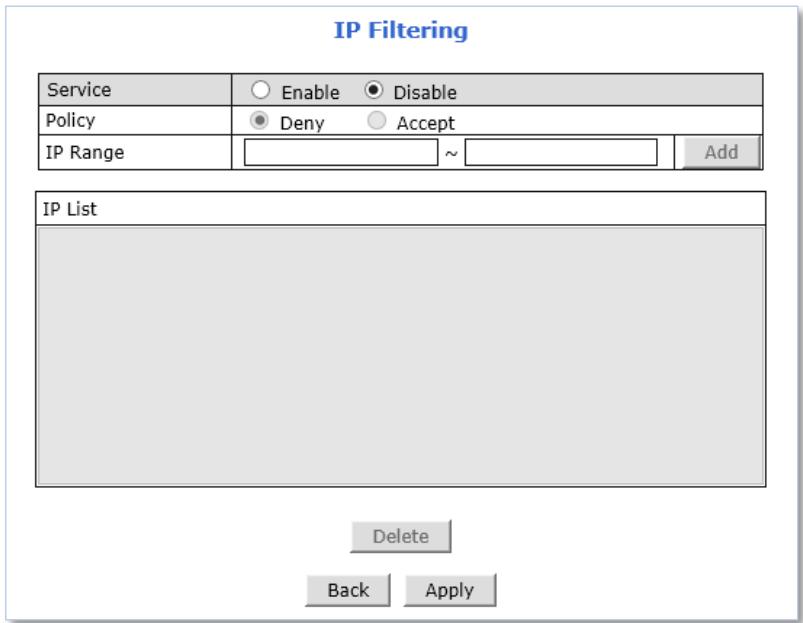
To use IP Filtering,
1) Enable the IP Filtering Service.
2) Select Policy.
3) Enter IP Range (for adding single IP, type the IP address in to the both 'From' and 'To' boxes).
4) Click Apply when you done entering IP.
To delete the IP or IP range, select the IP or IP range in the IP list and click Delete.
Note:
If "Deny" is selected for the policy option, The IP of the current PC which connected to the admin page should not be in the list to continue your settings.
If "Accept" is selected for the policy option, The IP of the current PC which connected to the admin page should be in the list to continue your settings.
8. System
System
This category shows the detailed method for System Configuration.
| » Name | Configuration of Network Video System name. |
| » Hostname | Configuration of OS Hostname. |
| » Date & Time | Configuration of Network Video System Date & Time. |
| » Admin. Password | Change administrator's password. |
| » Access Level | Configuration to allow other users. |
| » User | Add, Edit, Delete User ID & Password. |
8.1 Name
Server Name is used to identify all devices easily in the same network as example below.
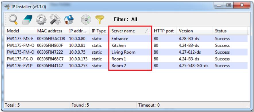
System information such as Product Model Name, Server Name, MAC address, Firmware Version and Web Image Version will be displayed in this page as shown below.
Name Setup
| Product model name | FW1176-FM-O-G |
| Server name | Network Video System |
| Mac Address (S/N) | |
| Firmware version | 4.31-011-rg_UI |
| Webimage version | FW |
Back
Apply
To change the Server Name, enter a new Server Name in the server name field and click Apply.
Note: Up to 21 alphanumeric or 10 Unicode characters can be used for server name. Server Name can be changed via IP Installer also. For more detailed information about IP Installer, please refer to IP Installer User Manual.
8.2 Hostname
Hostname is a label that is assigned to a device connected to a network and that is used to identify the device in network communication such as email, telnet.
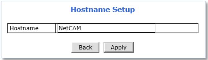
To change the Hostname, enter a new Hostname in the Hostname field and click Apply.
8.3 Date & Time
Applying the correct date and time is strongly recommended to avoid any confusion or errors caused by time difference between the FlexWATCH ^® device and client (remote access) PC.
When selecting Date & Time under System Configuration menu, Local Date & Time configuration setting page will be displayed as shown below.
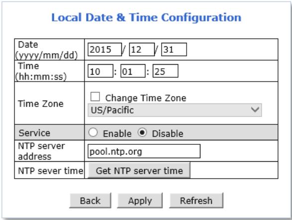
Date & Time can be set manually or automatically synced with a specified NTP (Network Time Protocol) server every 24 hours.
To change Date and Time manually, please follow the steps below:
1) Enter current Date and Time
2) Select Time Zone if necessary
a) Check on Change Time Zone
b) Select your region from the dropdown list
3) Click Apply
* Device reboot is required if Time Zone is changed.
To sync current time automatically with NTP server, please follow the steps below:
1) Select Time Zone if necessary
2) Enable Service
3) Enter NTP server address. (default = "pool.ntp.org")
* The NTP Server's IP address or host name must be specified.
4) Click Get NTP server time and then wait until the time changed
* If "Fail to get NTP server time" error message is appear, check the following status:
- Internet Connection
- NTP server
5) Click Apply
* Device reboot is required if Time Zone is changed.
Note: NTP (Network Time Protocol) is a protocol for synchronizing the clocks of the Network devices. With NTP service, you can synchronize your FlexWATCH® device to an internet time server.
8.4 Admin. Password
Administrator's password should be changed occasionally to secure the FlexWATCH® device.
When selecting Admin. Password under System menu, Administrator's Password configuration page will be displayed as shown below.
Administrator's Password Configuration
| Administrator's ID | root | |
| Old Password | ||
| New Password | ||
| Confirm Password | ||
To change the password for the administrator, please follow the steps below:
1) Enter current password in the Old Password field
2) Enter new password in the New Password and Confirm Password fields
3) Click Apply
4) Enter new password when login window appears
Note: Default ID for admin account is fixed with "root" and is not allowed to be changed. Password is encrypted when it stored in FlexWATCH® device. Therefore, there is no way to find out the password if lost. If the password has been lost, reset the device with FD (Factory Default) button on the device. In this case, all setting values will be factory defaulted.
8.5 Access Level
You can select whether to use password authentication when Smart (Live) Viewer login.
Note: Administrator's password should be changed occasionally to secure the FlexWATCH® device.
When selecting Access Level under System menu, Access control setting page will be displayed as shown below.
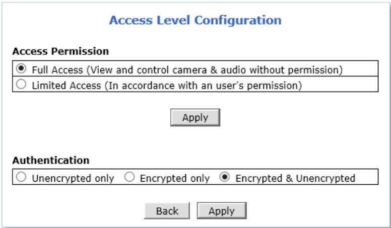
Access permission
• Full Access: Allow anonymous Smart (Live) Viewer login, authentication is not required.
- Limited Access: Allow registered user Smart (Live) Viewer login, authentication is required.
Authentication
- Unencrypted only: Authentication process is not encrypted.
- Encrypted only: Authentication process is encrypted using a Digest (MD5).
- Encrypted & Unencrypted: Both encrypted and unencrypted authentication can be used in the authentication process.
Note: Web browser must be restarted for applying any changes of access level.
8.6 User
Note: Limited Access must be set on the Access Level setting page for user's privilege or access permission.
Users can be added, modified, and/or deleted by the administrator. Once registered as Limited Access setting, the user can access the FlexWATCH ^® device with some limited privileges.
When selecting User Registration under System Configuration menu, User Registration setting page will be displayed as shown below.
User Registration (Add)
| Add | Edit | Delete |
| User ID | |||
| Password | |||
| Confirm password | |||
| Name | |||
Notice : User ID & Password must be alphanumeric within 23 characters.
| System Resource Access Permission | ||||||
| ◎ | All Channels Access | |||||
| ○ | General Access (only live viewing access) | |||||
| ○ | No Access | |||||
| ○ | Selective Access | |||||
| Enable | VS Module ID | Camera No. | Alarm Control | PTZ Control | Audio Control | Play back |
| Built-in Module 0 √ | All √ | |||||
| Built-in Module 0 √ | All √ | |||||
| Built-in Module 0 √ | All √ | |||||
| Built-in Module 0 √ | All √ | |||||
| Built-in Module 0 √ | All √ | |||||
| Built-in Module 0 √ | All √ | |||||
| built-in Module 0 √ | All √ | |||||
| Built-in Module 0 √ | All √ | |||||

Notice : To activate your setting at this 'User' menu,
- Click above "Apply" button.
- Go to 'System' -> 'Access Level'.
- Select "Limited Access".
- Click "Apply" button at the 'Access Level' page.
Otherwise, 'User' will not be activated.
8.6.1 Add
To add a new user, follow the steps below:
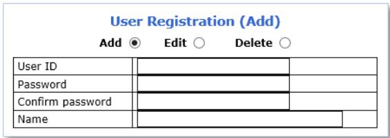
1) Select Add from the top 3 selection menu
2) Enter the new User ID you want to create
3) Enter new password in the New Password and Confirm Password fields for the new user
4) Enter user name
| System Resource Access Permission | ||||||
| ● | All Channels Access | |||||
| ○ | General Access (only live viewing access) | |||||
| ○ | No Access | |||||
| ○ | Selective Access | |||||
| Enable | VS Module ID | Camera No. | Alarm Control | PTZ Control | Audio Control | Play back |
| Built-in Module 0 √ | All √ | □ | □ | □ | □ | |
| Built-in Module 0 √ | All √ | □ | □ | □ | □ | |
| Built-in Module 0 √ | All √ | □ | □ | □ | □ | |
| Built-in Module 0 √ | All √ | □ | □ | □ | □ | |
| Built-in Module 0 √ | All √ | □ | □ | □ | □ | |
| Built-in Module0 √ | All √ | □ | □ | □ | □ | |
| Built-in Module 0 √ | All √ | □ | □ | □ | □ | |
| Built-in Module 0 √ | All √ | □ | □ | □ | □ | |
| Built-in Module 0 √ | All √ | □ | □ | □ | □ | |
5) Select one from the following access permission for the following features:
- Live Monitoring, Alarm control, PTZ control, Audio control, Playback
■ All Channels Access: The user has authority to access all channels and features
■ General Access (only live viewing access): Live monitoring is allowed only to the user
■ No Access: The user is not permitted to access the device at all
■ Selective Access: The user is allowed to access selected channels and features
6) If other than Selective Access permission is selected, skip to the step 11.
7) Check Enable to select access camera channel and features as shown below
| System Resource Access Permission | ||||||
| ○ | All Channels Access | |||||
| ○ | General Access (only live viewing access) | |||||
| ○ | No Access | |||||
| ● | Selective Access | |||||
| Enable | VS Module ID | Camera No. | Alarm Control | PTZ Control | Audio Control | Play back |
| √ | Built-in Module 0 √ | 1 √ | □ | √ | □ | √ |
| □ | Built-in Module 0 √ | All √ | □ | □ | □ | □ |
| □ | Built-in Module 0 √ | All √ | □ | □ | □ | □ |
| □ | Built-in Module 0 √ | All √ | □ | □ | □ | □ |
| □ | Built-in Module 0 √ | All √ | □ | □ | □ | □ |
| □ | Built-in Module 0 √ | All √ | □ | □ | □ | □ |
| □ | Built-in Module 0 √ | All √ | □ | □ | □ | □ |
| □ | Built-in Module 0 √ | All √ | □ | □ | □ | □ |
| □ | Built-in Module 0 √ | All √ | □ | □ | □ | □ |
| □ | Built-in Module 0 √ | All √ | □ | □ | □ | □ |
8) Select VS Module ID
- Bulit-in Module 0: Select for the FlexWATCH® camera models, 4 channel server models or 1\~4 camera channels of 8 channel server models
■ Built-in Module 1: Select for the camera channel 5\~8 of FlexWATCH® 8channel server models
9) Select Camera Number
10) Select the features for the selected channel
11) Click Apply
8.6.2 Edit
To edit a user account, follow the steps below:
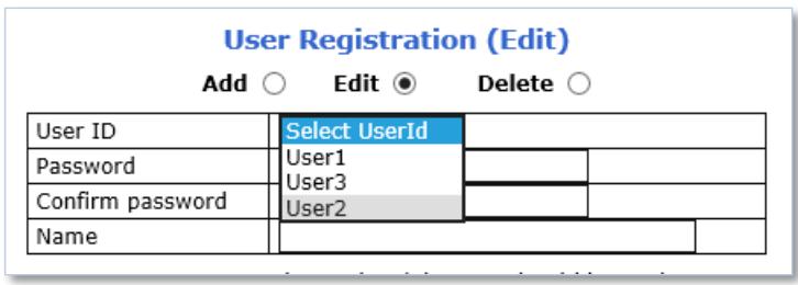
1) Select Edit from the top 3 selection menu
2) Select desired User ID to change the user account setting
3) After changing desired item, click Apply
8.6.3 Delete
To delete a user account, follow the steps below:
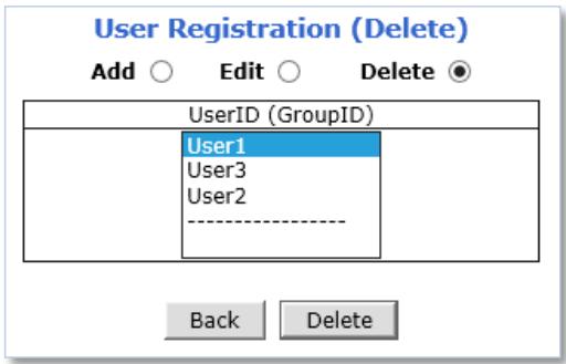
1) Select Delete from the top 3 selection menu
2) Select desired User ID to delete the user account
3) Click Delete
9. Advanced
Advanced features or services such as email notification, FTP, alarm out can be setup in this menu section.
9.1 Advanced Services
Pre-Alarm buffer size and buffering speed can be defined here.
Advanced Services
| Total pre-alarm buffer size : 5600 kbCurrent used buffer size : 0 frames |
| Ch 1 | Ch 2 | Sum | |||
| Pre-Alarm Buffer Size | 0 | (frames) | 0 | (frames) | 0 |
| Pre-Alarm Speed | Select Spei √ | Select Spei √ | |||
Save
- Pre-Alarm Buffer Size: You can set the buffer size which will store the images before event. The unit is in frame, and each channel can be set with different values. The total number of frames for Pre-Alarm buffer and Post-Alarm Buffer is limited to 10 frames.
- Pre-Alarm Speed: Buffering speed can be set. If it's set to Fastest, the server will store images as fast as it can. Each cannel can be set with different values.
9.1.1 E-mail
FlexWATCH ^® devices can notify via email if an event occurs.
E-mail Service Configuration
Please click the below link to configure E-mail service for each camera.
| Service | ○ Enable ● Disable | |
| SMTP server address | ||
| SMTP Port | 25 | (Default:25, 0 ~ 65535) |
| Authentication Login | No Authentication √ | |
| Char Set | US-ASCII (English) √ | |
| User ID | ||
| Password | ||
| Sender | ||
| 1st Recipient | ||
| 2nd Recipient | ||
| 3rd Recipient | ||
Back Save
To use E-mail notification service, follow the steps below.
1) Click a desired channel for the email notification service.
E-mail Service Configuration
Please click the below link to configure E-mail service for each camera.
| Service | ○ Enable ● Disable | |
| SMTP server address | ||
| SMTP Port | 25 | (Default:25, 0 ~ 65535) |
| Authentication Login | No Authentication √ | |
| Char Set | US-ASCII (English) √ | |
| User ID | ||
| Password | ||
| Sender | ||
| 1st Recipient | ||
| 2nd Recipient | ||
| 3rd Recipient | ||

2) Click the first Not Used Condition (Multiple condition can be combined and used)
E-mail Service Configuration at Camera 1
Please click below link to configure the service condition.
| Condition 1 | [Not Used] |
| Condition 2 | [Not Used] |
| Condition 3 | [Not Used] |
Maximum 10 pre-post alarm images can be transmitted.
| Pre-Alarm Buffer Size | 0 (frames) >> Check video buffer | ||
| Pre-Alarm Images | 0 √ | Post-Alarm Images | 0 √ |
| Pre-Alarm Speed | Select Speed √ | Post-Alarm Speed | Select Speed √ |
| Subject | Message From IP Device![0,0] | ||
?
3) When the condition page appears, Enable the selected Condition
Enable ● Disable ○
4) Select Mode
| Select Mode | ○ Always |
| ○ Schedule Only | |
| ● Event Only | |
| ○ Schedule and Event |
■ Always: [Please do not use this mode for Email notification.]
■ Schedule Only: [Please do not use this mode for Email notification.]
■ Event Only: Send email when selected event occurred
■ Schedule and Event: Send email when selected event occurs in specified time
5) Specify the Recording Schedule if necessary
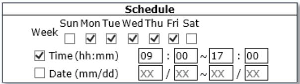
6) Select Event Type
| Event | ||||
| 1 | 2 | 3 | 4 | |
| Alarm Sensor | ||||
| Motion Detection | ✓ | |||
| External Input Data | ||||
| Camera Connected | ✓ | |||
| Camera Disconnected | ||||
| Boot Finished Serial Input | Enable Activated | |||
■ Event will be triggered by the followings:
• Alarm Sensor (Alarm Input)
- Motion Detection
• External Input Data such as POS.
- Camera Connection
- Connected
- Disconnected
- Boot Finished
- Serial Input
7) Click Save
8) When the following page appears, check the condition summary as marked in red below.
E-mail Service Configuration at Camera 1
| Please click below link to configure the service condition | |
| Condition 1 | [MON,TUE,WED,THU,FRI][09:00~17:00][M1][cC1][] |
| Condition 2 | [SUN,SAT][08:00~22:00][M1][] |
| Condition 3 | [Not Used] |
Maximum 10 pre-post alarm images can be transmitted.
| Pre-Alarm Buffer Size | 0 (frames) ×× Check video buffer | ||
| Pre-Alarm Images | 0 √ | Post-Alarm Images | 0 √ |
| Pre-Alarm Speed | Select Speed √ | Post-Alarm Speed | Select Speed √ |
| Subject | Message From IP Device![0,0] | ||
?
9) Select number of image frames for Pre and Post Alarm Images, and its speed.
10) Enter subject of the email.
11) Enter Messages (Contents of the email).
12) Click Save.
13) When the following page appears, enable the E-mail Service.
E-mail Service Configuration
Please click the below link to configure E-mail service for each camera.
| Service | ● Enable ○ Disable | ||
| SMTP server address | smtp.google.com | ||
| SMTP Port | 587 | (Default:25, 0 ~ 65535) | |
| Authentication Login | Authentication + TLS √ | ||
| Char Set | US-ASCII (English) √ | ||
| User ID | flexwatch@gmail.com | ||
| Password | ●●●●● | ||
| Sender | flexwatch@gmail.com | ||
| 1st Recipient | test1@gmail.com | ||
| 2nd Recipient | test2@yahoo.com | ||
| 3rd Recipient | test3@live.com | ||
Back
Save
14) Enter SMTP server address.
15) Enter SMTP port that the SMTP server using.
16) Select Authentication type of the SMTP server.
17) Select Character sets.
18) Enter User ID and Password.
19) Enter Sender's email address.
20) Enter Recipients' email addresses.
21) Click Save.
22) When the following page appears, enter Pre-Alarm Buffer Frames.
Advanced Services
Total pre-alarm buffer size : 5600 kb
Current used buffer size : 0 frames
| Ch 1 | Ch 2 | Sum | |
| Pre-Alarm Buffer Size | 3 (frames) | 0 (frames) | 0 |
| Pre-Alarm Speed | 1.0f/s √ | fastest √ |
Save
Notice : Pre-alarm buffer size for each camera will be applied for E-mail, and FTP(Buffered) service. Please click to "Save" button to apply new changes.
| Configuration of E-mail service to send pre-post alarm images. | |
| » FTP(Buffered) | Configuration of ftp service to send pre-post alarm images. |
| » FTP(Periodic) | Configuration of ftp service to send recent images periodically according to service conditions. |
| » Sensor Notification | Configuration to notify sensor status to predefined IP address. |
| » Alarm Output | Configuration of alarm output duration according to service conditions. |
Back
Apply
| Status | Start | Stop |
23) Select Pre-Alarm Speed.
24) Click Save.
25) Click Apply as shown below.
Advanced Services
Total pre-alarm buffer size : 5600
kb
Current used buffer size : 3
frames
| Ch 1 | Ch 2 | Sum | |||
| Pre-Alarm Buffer Size | 3 | (frames) | 0 | (frames) | 3 |
| Pre-Alarm Speed | 1.0f/s | √ | fastest | √ | |
| Ch 2 | Sum | |
| 0 | (frames) | 3 |
| fastest | √ | |
Save
Notice : Pre-alarm buffer size for each camera will be applied for E-mail, and FTP(Buffered) service.
Please click to "Save" button to apply new changes.
| Configuration of E-mail service to send pre-post alarm images. | |
| » FTP(Buffered) | Configuration of ftp service to send pre-post alarm images. |
| » FTP(Periodic) | Configuration of ftp service to send recent images periodically according to service conditions. |
| » Sensor Notification | Configuration to notify sensor status to predefined IP address. |
| » Alarm Output | Configuration of alarm output duration according to service conditions. |
Back
Apply
Status
Start
Stop
9.1.2 FTP (Buffered)
In Buffering Service, a series of images are continuously being stored in a buffer memory of the camera/server for a certain period of time. When the camera/server is triggered by an event or schedule, the images or alarm status just before and after the event/schedule are sent to FTP server.
To use FTP (Buffered) service, follow the steps below.
1) Click a desired channel for the FTP (Buffered) service.
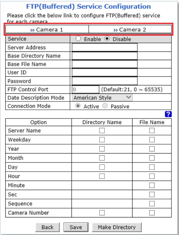
2) Click the first Not Used Condition (Multiple condition can be combined and used)
![FTP(Buffered) Service Configuration at Camera 1 Please click below link to configure the service condition. » Condition 1 [Not Used] » Condition 2 [Not Used] » Condition 3 [Not Used] Maximum 256 pre-post alarm images can be transmitted. Pre-Alarm Buffer Size 3 (frames) >> Check video buffer Pre-Alarm Images 0 frames Post-Alarm Images 0 frames Pre-Alarm Speed 1.0f/s ▼ Post-Alarm Speed Select Speed ▼ Back Save](/content/2019/12/21144/images/d8a4fa27e4031d23e02a73ece1d86f96424881d226980e6ab0f5633f5a8ca40f.jpg)
3) When the condition page appears, Enable the selected Condition

4) Select Mode
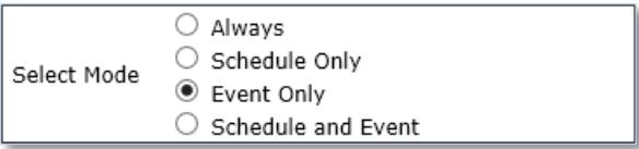
■ Always: [Please do not use this mode for Email notification.]
■ Schedule Only: [Please do not use this mode for Email notification.]
■ Event Only: Send email when selected event occurred
■ Schedule and Event: Send email when selected event occurs in specified time
5) Specify the Recording Schedule if necessary
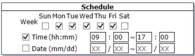
6) Select Event Type
| Event | ||||
| 1 | 2 | 3 | 4 | |
| Alarm Sensor | ||||
| Motion Detection | ✓ | |||
| External Input Data | ||||
| Camera Connected | ✓ | |||
| Camera Disconnected | ||||
| Boot Finished Serial Input | Enable Activated | |||
■ Event will be triggered by the followings:
• Alarm Sensor (Alarm Input)
- Motion Detection
• External Input Data such as POS.
- Camera Connection
- Connected
- Disconnected
- Boot Finished
- Serial Input
7) Click Save
8) When the following page appears, check the condition summary as marked in red below.
FTP(Buffered) Service Configuration at Camera 1
Please click below link to configure the service condition.
| Condition 1 | [M1][] |
| Condition 2 | [Not Used] |
| Condition 3 | [Not Used] |
Maximum 256 pre-post alarm images can be transmitted.
| Pre-Alarm Buffer Size | 3 (frames) ×× Check video buffer | ||||
| Pre-Alarm Images | 0 | frames | Post-Alarm Images | 0 | frames |
| Pre-Alarm Speed | 1.0f/s √ | Post-Alarm Speed | Select Speed √ | ||

9) Enter the number of Pre-Alarm Image frames.
(The number of Pre-alarm images must be equal or less than Pre-Alarm Buffer Size.)
10) Enter the number of Post-Alarm Image frames and select Post-Alarm Speed, if necessary.
11) Click Save.
12) When the following page appears, Enable the FTP(Buffered) service.
FTP(Buffered) Service Configuration
Please click the below link to configure FTP(Buffered) service for each camera.
| » Camera 1 | » Camera 2 | ||
| Service | ○ Enable ● Disable | ||
| Server Address | |||
| Base Directory Name | |||
| Base File Name | |||
| User ID | |||
| Password | |||
| FTP Control Port | 0 | (Default:21, 0 ~ 65535) | |
| Date Description Mode | American Style √ | ||
| Connection Mode | ● Active ○ Passive | ||
?
| Option | Directory Name | File Name |
| Server Name | ||
| Weekday | ||
| Year | ||
| Month | ||
| Day | ||
| Hour | ||
| Minute | ||
| Sec | ||
| Sequence | ||
| Camera Number |

13) Enter FTP server address.
14) Enter Base Directory Name. (The directory in FTP server where the data will be uploaded)
15) Enter Base File Name.
16) Enter FTP Control Port number.
17) Select Data Description Mode for FTP server.
18) Select Connection mode for FTP server.
19) Select name configurations of directory and files.
20) Click Make Directory.
21) When the following page appears, Click Apply.
Advanced Services
| Total pre-alarm buffer size : 5600 kbCurrent used buffer size : 0 frames |
| Ch 1 | Ch 2 | Sum | |
| Pre-Alarm Buffer Size | 3 (frames) | 0 (frames) | 0 |
| Pre-Alarm Speed | 1.0f/s √ | fastest √ |
Save
Notice : Pre-alarm buffer size for each camera will be applied for E-mail, and FTP(Buffered) service. Please click to "Save" button to apply new changes.
| Configuration of E-mail service to send pre-post alarm images. | |
| » FTP(Buffered) | Configuration of ftp service to send pre-post alarm images. |
| » FTP(Periodic) | Configuration of ftp service to send recent images periodically according to service conditions. |
| » Sensor Notification | Configuration to notify sensor status to predefined IP address. |
| » Alarm Output | Configuration of alarm output duration according to service conditions. |
Back
Apply
| Status | Start | Stop |
9.1.3 FTP (Periodic)
In Periodic Service, only the image, alarm/sensor status after an event/schedule is reported to you upon the server being triggered.
To use FTP (Periodic) service, follow the steps below.
1) Click a desired channel for the FTP (Periodic) service.
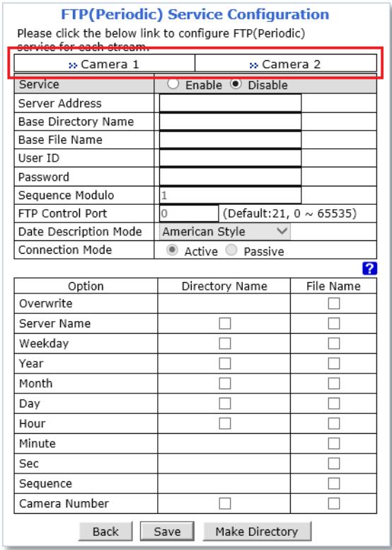
2) Click the first Not Used Condition (Multiple condition can be combined and used)
![FTP(Periodic) Service Configuration at Camera1 Please click below link to configure the service condition. Condition 1 [Not Used] Condition 2 [Not Used] Condition 3 [Not Used] FTP interval (msec) 0 msec Back Save](/content/2019/12/21144/images/eccbc6ca81bd941b80deba13545acdf3a51631971866a316d9f7b48c9304ad95.jpg)
3) When the condition page appears, Enable the selected Condition

4) Select Mode
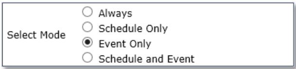
■ Always: [Please do not use this mode for Email notification.]
■ Schedule Only: [Please do not use this mode for Email notification.]
■ Event Only: Send email when selected event occurred
■ Schedule and Event: Send email when selected event occurs in specified time
5) Specify the Recording Schedule if necessary
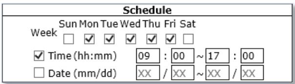
6) Select Event Type
| Event | ||||
| 1 | 2 | 3 | 4 | |
| Alarm Sensor | □ | □ | □ | □ |
| Motion Detection | ✓ | □ | □ | □ |
| External Input Data | □ | |||
| Camera Connected | ✓ | □ | □ | □ |
| Camera Disconnected | □ | □ | □ | □ |
| Boot Finished | □ Enable | |||
| Serial Input | □ Activated | |||
■ Event will be triggered by the followings:
• Alarm Sensor (Alarm Input)
- Motion Detection
• External Input Data such as POS.
- Camera Connection
- Connected
- Disconnected
- Boot Finished
- Serial Input
7) Click Save
8) When the following page appears, check the condition summary as marked in red below.
![FTP(Periodic) Service Configuration at Camera1 Please click below link to configure the service condition. Condition 1 [M1][] Condition 2 [Not Used] Condition 3 [Not Used] FTP interval (msec) | 0 msec Back Save](/content/2019/12/21144/images/cd38b34497f4fc6bcee570bbc835bde3435024894a048b380843d80e23a9daf6.jpg)
9) Enter FTP upload interval (millisecond).
10) Click Save.
11) When the following page appears, Enable the FTP (Periodic) service.
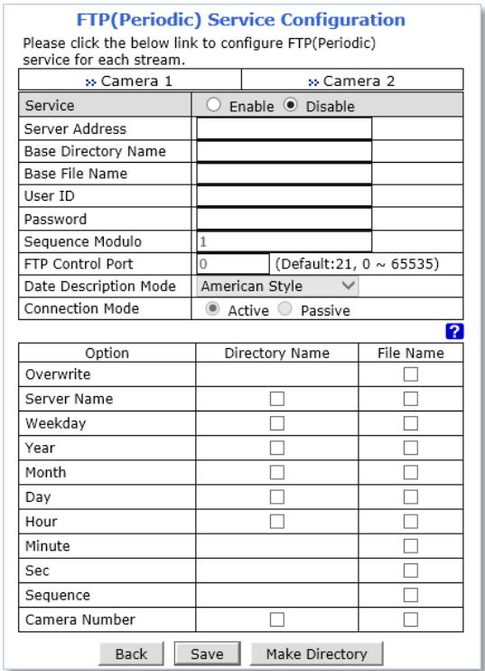
12) Enter FTP server address.
13) Enter Base Directory Name. (The directory in FTP server where the data will be uploaded)
14) Enter Base File Name.
15) Enter FTP Control Port number.
16) Select Data Description Mode for FTP server.
17) Select Connection mode for FTP server.
18) Select name configurations of directory and files.
19) Click Make Directory to create the directory in the FTP server.
20) Click Save.
21) When the following page appears, Click Apply.
Advanced Services
| Total pre-alarm buffer size : 5600 kb |
| Current used buffer size : 0 frames |
| Ch 1 | Ch 2 | Sum | |
| Pre-Alarm Buffer Size | 3 (frames) | 0 (frames) | 0 |
| Pre-Alarm Speed | 1.0f/s √ | fastest √ |
Save
Notice : Pre-alarm buffer size for each camera will be applied for E-mail, and FTP(Buffered) service. Please click to "Save" button to apply new changes.
| Configuration of E-mail service to send pre-post alarm images. | |
| » FTP(Buffered) | Configuration of ftp service to send pre-post alarm images. |
| » FTP(Periodic) | Configuration of ftp service to send recent images periodically according to service conditions. |
| » Sensor Notification | Configuration to notify sensor status to predefined IP address. |
| » Alarm Output | Configuration of alarm output duration according to service conditions. |
Back Apply
Status Start Stop
9.1.4 Sensor Notification
When event occurs, the CGI or Alarm messages can be sent to a specific IP.
To use Sensor Notification, follow the steps below.
1) Click a desired input number for the Sensor notification service.
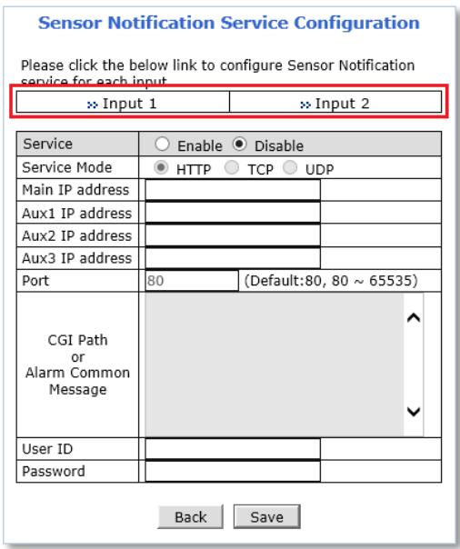
2) Click the first Not Used Condition (Multiple condition can be combined and used)
![Sensor Notification Service Configuration at Input 1 Please click below link to configure the service condition Condition 1 [Not Used] Condition 2 [Not Used] Condition 3 [Not Used] CGI Name or Alarm Port Message Back Save](/content/2019/12/21144/images/911f676cf397798af21d05a50d9c4b83452bea68ef3c512c67a6fd9502d9f44a.jpg)
0
3) When the condition page appears, Enable the selected Condition

4) Select Mode
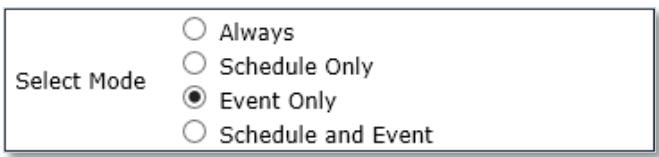
■ Always: [Please do not use this mode for Email notification.]
■ Schedule Only: [Please do not use this mode for Email notification.]
■ Event Only: Send email when selected event occurred
- Schedule and Event: Send email when selected event occurs in specified time
5) Specify the Recording Schedule if necessary
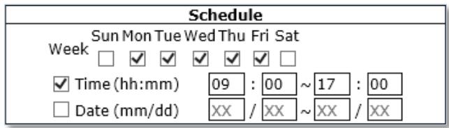
6) Select Event Type
| Event | ||||
| 1 | 2 | 3 | 4 | |
| Alarm Sensor | ||||
| Motion Detection | ✓ | |||
| External Input Data | ||||
| Camera Connected | ✓ | |||
| Camera Disconnected | ||||
| Boot Finished Serial Input | Enable Activated | |||
■ Event will be triggered by the followings:
• Alarm Sensor (Alarm Input)
- Motion Detection
• External Input Data such as POS.
- Camera Connection
- Connected
- Disconnected
- Boot Finished
- Serial Input
7) Click Save
8) When the following page appears, check the condition summary as marked in red below.
Sensor Notification Service Configuration at Input 1
Please click below link to configure the service condition
| Condition 1 | [Not Used] |
| Condition 2 | [Not Used] |
| Condition 3 | [Not Used] |
| CGI Name or Alarm Port Message | A ✓ |
Back Save
9) Enter CGI Name or Alarm Port Message.
10) Click Save.
11) When the following page appears, Enable the Sensor Notification service.
Sensor Notification Service Configuration
Please click the below link to configure Sensor Notification service for each input.
| × Input 1 | × Input 2 | ||
| Service | ○ Enable ● Disable | ||
| Service Mode | ● HTTP ○ TCP ○ UDP | ||
| Main IP address | |||
| Aux1 IP address | |||
| Aux2 IP address | |||
| Aux3 IP address | |||
| Port | 80 | (Default:80, 80 ~ 65535) | |
| CGI Path or Alarm Common Message | |||
| User ID | |||
| Password | |||
Back
Save
12) Select Service mode or Protocol type.
13) Enter IP addresses for the devices that will receive CGI or Alarm Message.
14) Enter Port number.
15) Enter CGI path or Alarm Common Message.
16) Enter User ID and Password if necessary.
17) Click Save.
18) When the following page appears, Click Apply.
Advanced Services
Total pre-alarm buffer size : 5600 kb Current used buffer size : 0 frames
| Ch 1 | Ch 2 | Sum | |||
| Pre-Alarm Buffer Size | 3 | (frames) | 0 | (frames) | 0 |
| Pre-Alarm Speed | 1.0f/s | √ | fastest | √ | |
Save
Notice : Pre-alarm buffer size for each camera will be applied for E-mail, and FTP(Buffered) service. Please click to "Save" button to apply new changes.
| Configuration of E-mail service to send pre-post alarm images. | |
| » FTP(Buffered) | Configuration of ftp service to send pre-post alarm images. |
| » FTP(Periodic) | Configuration of ftp service to send recent images periodically according to service conditions. |
| » Sensor Notification | Configuration to notify sensor status to predefined IP address. |
| » Alarm Output | Configuration of alarm output duration according to service conditions. |
Back
Apply
| Status | Start | Stop |
9.1.5 Alarm Output
When event occurs; the FlexWATCH™ device can be triggered external alarm.
To use Alarm Output, follow the steps below.
1) Click a desired Output number for the Alarm out service.
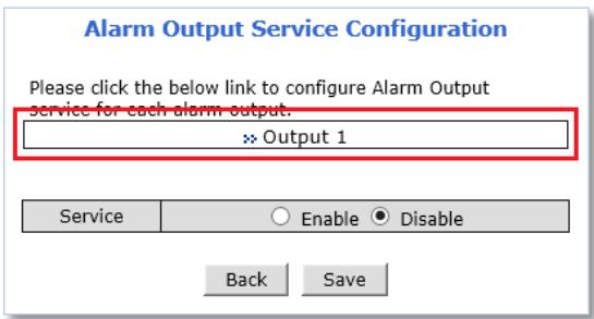
2) Click the first Not Used Condition (Multiple condition can be combined and used)
![Alarm Output Service Configuration at Input 1 Please click below link to configure the service condition. >> Condition 1 [Not Used] >> Condition 2 [Not Used] >> Condition 3 [Not Used] Alarm Output Duration Infinite √ sec Back Save](/content/2019/12/21144/images/a37022be489c955c02c8b67c5961c54e5bcb73c881ecabcdc7927288c277c7fa.jpg)
3) When the condition page appears, Enable the selected Condition

4) Select Mode
| Select Mode | ○ Always |
| ○ Schedule Only | |
| ● Event Only | |
| ○ Schedule and Event |
■ Always: [Please do not use this mode for Email notification.]
■ Schedule Only: [Please do not use this mode for Email notification.]
■ Event Only: Send email when selected event occurred
■ Schedule and Event: Send email when selected event occurs in specified time
5) Specify the Recording Schedule if necessary
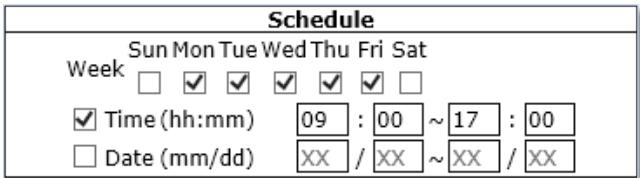
6) Select Event Type
| Event | ||||
| 1 | 2 | 3 | 4 | |
| Alarm Sensor | ||||
| Motion Detection | ✓ | |||
| External Input Data | ||||
| Camera Connected | ✓ | |||
| Camera Disconnected | ||||
| Boot Finished Serial Input | Enable Activated | |||
■ Event will be triggered by the followings:
• Alarm Sensor (Alarm Input)
- Motion Detection
• External Input Data such as POS.
- Camera Connection
- Connected
- Disconnected
- Boot Finished
- Serial Input
7) Click Save
8) When the following page appears, check the condition summary as marked in red below.
![Alarm Output Service Configuration at Input 1 Please click below link to configure the service condition Condition 1 [M1][] Condition 2 [Not Used] Condition 3 [Not Used] Alarm Output Duration Infinite √ sec Back Save](/content/2019/12/21144/images/44866aad192761b99b61ede7058f37d4b538a1db5dc45d11b7bd3d61c2644bd9.jpg)
9) Select Alarm Output Duration time.
10) Click Save.
11) When the following page appears, Enable the Alarm Output service.
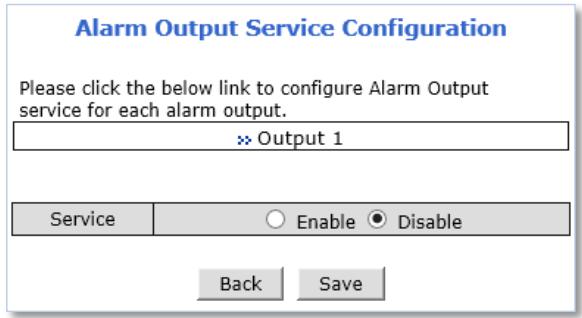
12) Click Save.
13) When the following page appears, Click Apply.
Advanced Services
Total pre-alarm buffer size : 5600 kb
Current used buffer size : 0 frames
| Ch 1 | Ch 2 | Sum | |||
| Pre-Alarm Buffer Size | 3 | (frames) | 0 | (frames) | 0 |
| Pre-Alarm Speed | 1.0f/s | √ | fastest | √ | |
Save
Notice : Pre-alarm buffer size for each camera will be applied for E-mail, and FTP(Buffered) service. Please click to "Save" button to apply new changes.
| Configuration of E-mail service to send pre-post alarm images. | |
| FTP(Buffered) | Configuration of ftp service to send pre-post alarm images. |
| FTP(Periodic) | Configuration of ftp service to send recent images periodically according to service conditions. |
| Sensor Notification | Configuration to notify sensor status to predefined IP address. |
| Alarm Output | Configuration of alarm output duration according to service conditions. |
Back
Apply
| Status | Start | Stop |
10. Utilities
System management tools are contained in this menu.
10.1 Log
System log file provides you the information about when and who access' the contents of FlexWATCH® device such as HTTP file or CGI programs. In each line, log data consists of date, time, category, IP address, user ID as shown below.
![System Log [Thu Sep 11 17:43:22 2014 0+900] Live : 10.10.228.1 (anonymous) [Thu Sep 11 17:43:22 2014 0+900] Live : 10.10.245.1 (anonymous) [Thu Sep 11 17:43:23 2014 0+900] Live : 10.10.228.1 (anonymous) [Thu Sep 11 17:43:24 2014 0+900] Live : 10.10.245.1 (anonymous) [Thu Sep 11 17:44:24 2014 0+900] Live : 10.10.245.1 (anonymous) [Thu Sep 11 17:45:37 2014 0+900] Live : 10.10.245.1 (anonymous) [Thu Sep 11 17:47:36 2014 0+900] Live : 10.10.245.1 (anonymous) [Thu Sep 11 17:48:28 2014 0+900] Live : 10.10.245.1 (anonymous) [Thu Sep 11 17:49:04 2014 0+900] Home : 10.10.228.1 (anonymous) [Thu Sep 11 17:49:08 2014 0+900] Live : 10.10.228.1 (anonymous) [Thu Sep 11 17:49:17 2014 0+900] Live : 10.10.245.1 (anonymous) [Thu Sep 11 17:49:27 2014 0+900] Admin : 10.10.228.1 root [Thu Sep 11 17:49:38 2014 0+900] Admin : 10.10.228.1 root [Thu Sep 11 17:49:46 2014 0+900] Live : 10.10.245.1 (anonymous) [Thu Sep 11 17:49:46 2014 0+900] Live : 10.10.228.1 (anonymous) [Thu Sep 11 17:49:46 2014 0+900] Live : 10.10.228.1 (anonymous) [Fri Sep 12 14:42:57 2014 0+900] Live : 192.168.228.1 (anonymous) [Fri Sep 12 14:43:00 2014 0+900] Live : 192.168.228.1 (anonymous) [Fri Sep 12 14:43:04 2014 0+900] Live : 192.168.228.1 (anonymous) [Fri Sep 12 14:43:07 2014 0+900] Live : 192.168.228.1 (anonymous) [Fri Sep 12 14:43:08 2014 0+900] Live : 192.168.228.1 (anonymous) [Fri Sep 12 14:54:21 2014 0+900] Live : 192.168.228.1 (anonymous) [Fri Sep 12 14:55:28 2014 0+900] Live : 192.168.228.1 (anonymous) [Fri Sep 12 14:55:30 2014 0+900] Live : 192.168.228.1 (anonymous) [Fri Sep 12 14:55:58 2014 0+900] Live : 192.168.228.1 (anonymous) [Fri Sep 12 15:00:33 2014 0+900] Live : 192.168.228.1 (anonymous) [Fri Sep 12 17:50:05 2014 0+900] Home : 192.168.228.1 (anonymous) [Fri Sep 12 18:04:25 2014 0+900] Home : 192.168.225.1 (anonymous)](/content/2019/12/21144/images/9fddd34ef6e1d825890bdbea7da1f3dd3e63f519a459aa4d482f3785f47e1e3d.jpg)
10.2 Reboot
It is recommended to reboot the system after making changes to the configuration.
To reboot, click Reboot as shown below.
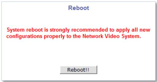
To Restore Default, click Restore Default as shown below and follow the instructions on the screen
Restore Default
All of setting will be revert back to restore default except IP address, if you press "Restore Default" button.
Back
Restore Default
10.4 System Update
FlexWATCH ^® device firmware and drivers for external devices can be updated in this menu.
Update
| Firmware Update | Start |
| PTZ Device Driver Update | Start |
| Sensor Device Driver Update | Start |
Back
| System Information | |
| Mac Address (S/N) | 00:30:6F:84:4D:01 |
| Firmware version | 4.31-011-rg_UI |
| Flexible Extra System Information | |
| System | No Extra System |
| Version | 0.00.0000 |
■ Firmware Update: Update FlexWATCH™ device firmware.
■ PTZ Device Driver Update: Update or add a PTZ driver.
■ Sensor Device Driver Update: Update or add a Sensor device driver.
■ Flexible Extra System (FES): Update FES driver files.
To system update, click the Start button of desired update item and follow the instructions on the screen.
Note: Firmware update can be done with FlexWATCH® IP Installer software.
Note: If Web browser's pop-up blocker is turned on, update window may not appear. In this case, disable the pop-up blocker and then proceed to upgrade the system.

Seyeon Tech Co., Ltd.
Seyeon Tech Co., Ltd.
HEAD OFFICE
| - Address | #404, Gayang Techno Town, 217, Heojun-ro, Gangseo-gu, Seoul, 157-193, South KOREA |
| - PHONE | +82-2-2192-6800 |
| - FAX | +82-2-2659-0831 |
| sales@flexwatch.com |
US Office
| - Address | 4050 N. Palm St. #501, Fullerton CA 92835, USA |
| - PHONE | +1-323-262-3682 |
| - FAX | +1-714-994-1593 |
| support@flexwatch.com |
www.FlexWATCH.co.kr
www.FlexWATCH.com