USER MANUAL FNA-A DAIKIN
3MXS40K2V1B 3MXS68G2V1B 4MXS80E2V3B
3MXS52E3V1B 4MXS68F2V1B 5MXS90E2V3B
Indoor Unit
FTXG25JV1BW FVXG25K2V1B FCQG35FVEB
FTXG25JV1BA FVXG35K2V1B FCQG50FVEB
FTXG35JV1BW FVXG50K2V1B FCQG60FVEB
FTXG35JV1BA FVXS25FV1B FFQ25B9V1B
FTXG50JV1BW FVXS35FV1B FFQ35B9V1B
FTXG50JV1BA FVXS50FV1B FFQ50B9V1B
CTXS15K2V1B FLXS25BAVMB FFQ60B9V1B
FTXS20K2V1B FLXS35BAVMB FHQ35BWV1B
FTXS25K2V1B FLXS50BAVMB FHQ50BWV1B
CTXS35K2V1B FLXS60BAVMB FHQ60BWV1B
FTXS25J2V1B FDXS25E7VMB FDBQ25B8V1
FTXS35J2V1B FDXS35E7VMB FBQ35C8VEB
FTXS42J2V1B FDXS50C7VMB FBQ50C8VEB
FTXS50J2V1B FDXS60C7VMB FBQ60C8VEB
FTXS60GV1B
FTXS71GV1B
- Introduction vii
1.1 Safety Cautions vii
1.2 Used Icons xi
Part 1 List of Functions 1
- Cooling Only 2
1.1 Outdoor Unit 2
1.2 Indoor Unit 3
- Heat Pump 6
2.1 Outdoor Unit 6
2.2 Indoor Unit 7
Part 2 Specifications 14
- Cooling Only 15
1.1 Outdoor Unit 15
1.2 Indoor Unit 17
- Heat Pump 22
2.1 Outdoor Unit 22
2.2 Indoor Unit 25
Part 3 Printed Circuit Board Connector Wiring Diagram 37
- Outdoor Unit 38
- Indoor Unit 41
2.1 FTXG25/35/50JV1BW(A) 41
2.2FTXS20/25K2V1B,CTXS15/35K2V1B 44
2.3FTXS25/35/42/50J2V1B 46
2.4FTXS60/71GV1B 49
2.5 FVXG25/35/50K2V1B 52
2.6 FVXS25/35/50FV1B 55
2.7 FLXS25/35/50/60BAVMB 57
2.8 FDXS25/35E7VMB, FDXS50/60C7VMB 59
2.9 FCQG35/50/60FVEB 61
2.10 FFQ25/35/50/60B9V1B 64
2.11 FHQ35/50/60BWV1B 66
2.12 FDBQ25B8V1 68
2.13 FBQ35/50/60C8VEB .70
- Wired Remote Controller 73
3.1 BRC1D528 73
3.2 BRC1E52A7, BRC1E52B7. 74
Part 4 Function and Control. 75
- Indoor Unit Control (RA Models) 76
1.1 Temperature Control 76
1.2 Frequency Principle 76
1.3 Operation Starting Control 78
1.4 Airflow Direction Control 79
1.5 Fan Speed Control for Indoor Unit 82
1.6 RADIANT Operation 83
1.7 Program Dry Operation 85
1.8 Automatic Operation 86
1.9 Thermostat Control 87
1.10 NIGHT SET Mode 89
1.11 ECONO Operation 90
1.12 HOME LEAVE Operation 91
1.13 INTELLIGENT EYE Operation 92
1.14 2-Area INTELLIGENT EYE Operation .93
1.15 Inverter POWERFUL Operation 95
1.16 Multi-Colored Indicator Lamp / TIMER Lamp 95
1.17 Other Functions 97
- Indoor Unit Control (SA Models) 99
2.1 Drain Pump Control 99
2.2 Thermostat Sensor in Remote Controller 101
2.3 Freeze Prevention Control 103
2.4 Hot Start Control (In Heating Operation Only) 104
-
Function of Thermistor 105
-
Control Specification 107
4.1 Mode Hierarchy 107
4.2 Frequency Control 108
4.3 Controls at Mode Changing / Start-up 111
4.4 Discharge Pipe Temperature Control 112
4.5 Input Current Control 113
4.6 Freeze-up Protection Control 113
4.7 Heating Peak-cut Control 114
4.8 Outdoor Fan Control 115
4.9 Liquid Compression Protection Function 115
4.10 Defrost Control 116
4.11 Low Hz High Pressure Limit 117
4.12 Outdoor Electronic Expansion Valve Control 117
4.13 Malfunctions 122
Part 5 Operation Manual. 124
- System Configuration 125
- RA Indoor Unit 126
2.1 FTXG, FTXS-K, CTXS, FVXG Series - ARC466A1, A2, A6 126
2.2FTXS-J,FTXS-G,FVXS Series -ARC452A1,A3 178
2.3 FLXS, FDXS Series - ARC433B67, B69 218
- SA Indoor Unit 233
3.1 BRC1D528 233
Part 6 Service Diagnosis. 248
- Troubleshooting with LED 250
1.1 Indoor Unit 250
1.2 Outdoor Unit 252
-
Problem Symptoms and Measures 253
-
Service Check Function 254
3.1 RA Indoor Unit - FTXG, FTXS, CTXS, FVXG, FVXS, FLXS, FDXS Series 254
3.2 SA Indoor Unit - FCQG, FFQ, FHQ, FDBQ, FBQ Series 263
- Code Indication on Remote Controller 267
4.1 RA Indoor Unit - FTXG, FTXS, CTXS, FVXG, FVXS, FLXS, FDXS Series 267
4.2 SA Indoor Unit - FCQG, FFQ, FHQ, FDBQ, FBQ Series 267
4.3 Sub Codes for SA Indoor Unit 268
4.4 Outdoor Unit 269
- Troubleshooting for RA Indoor Unit - FTXG, FTXS, CTXS, FVXG, FVXS, FLXS, FDXS Series 270
5.1 Indoor Unit PCB Abnormality 270
5.2 Freeze-up Protection Control or Heating Peak-cut Control 272
5.3 Fan Motor or Related Abnormality 274
5.4 Radiant Panel Temperature Rise, Indoor Electronic Expansion Valve (Motor Operated Valve) Abnormality, Freeze-up Protection Control (FVXG Series Only). 278
5.5 Thermistor or Related Abnormality (RA Indoor Unit) 280
5.6 Front Panel Open / Close Fault (FTXG Series Only) 281
5.7 Signal Transmission Error (between Indoor Unit and Outdoor Unit) .....282
5.8 Unspecified Voltage (between Indoor Unit and Outdoor Unit) 283
- Troubleshooting for SA Indoor Unit - FCQG, FFQ, FHQ, FDBQ, FBQ Series 284
6.1 Indoor Unit PCB Abnormality 284
6.2 Drain Water Level System Abnormality 285
6.3 Fan Motor or Related Abnormality 287
6.4 Swing Motor Lock (FHQ Series Only) 289
6.5 Drain System Abnormality 290
6.6 Thermistor or Related Abnormality (SA Indoor Unit) 291
6.7 Remote Controller Thermistor Abnormality 292
6.8 Signal Transmission Error (between Indoor Unit and Remote Controller) 293
6.9 Signal Transmission Error (between MAIN Remote Controller and SUB Remote Controller)......294
6.10 Field Setting Abnormality 295
- Troubleshooting for Outdoor Unit 296
7.1 Refrigerant Shortage 296
7.2 Low-voltage Detection or Over-voltage Detection 298
7.3 Signal Transmission Error (on Outdoor Unit PCB) 300
7.4 Unspecified Voltage (between Indoor Unit and Outdoor Unit) / Anti-icing Function in Other Rooms 301
7.5 Anti-icing Function 302
7.6 Outdoor Unit PCB Abnormality 304
7.7 OL Activation (Compressor Overload) 305
7.8 Compressor Lock 306
7.9 DC Fan Lock 307
7.10 Input Overcurrent Detection 308
7.11 Discharge Pipe Temperature Control 309
7.12 High Pressure Control in Cooling 310
7.13 Compressor Sensor System Abnormality 311
7.14 Position Sensor Abnormality 313
7.15 CT or Related Abnormality 315
7.16 Thermistor or Related Abnormality (Outdoor Unit) 317
7.17 Electrical Box Temperature Rise 319
7.18 Radiation Fin Temperature Rise 321
7.19 Output Overcurrent Detection 323
- Check 325
8.1 Thermistor Resistance Check 325
8.2 Fan Motor Connector Check 326
8.3 Hall IC Check 327
8.4 Indoor Electronic Expansion Valve Coil Check 327
8.5 Power Supply Waveform Check 328
8.6 Outdoor Electronic Expansion Valve Check 329
8.7 Four Way Valve Performance Check 330
8.8 Inverter Unit Refrigerant System Check 330
8.9 "Inverter Checker" Check 331
8.10 Rotation Pulse Check on the Outdoor Unit PCB 332
8.11 Installation Condition Check 333
8.12 Discharge Pressure Check 333
8.13 Outdoor Fan System Check 334
8.14 Capacitor Voltage Check 334
8.15 Power Module Check 335
Part 7 Removal Procedure 336
- Outdoor Unit: 40-75 Class 337
1.1 Removal of Outer Panels 337
1.2 Removal of Electrical Box 341
1.3 Removal of PCBs 349
1.4 Removal of Outdoor Fan / Fan Motor 354
1.5 Removal of Sound Blankets 356
1.6 Removal of Coils / Thermistors 360
1.7 Removal of Distributor 363
1.8 Removal of Four Way Valve 364
1.9 Removal of Compressor 365
- Outdoor Unit: 80/90 Class 367
2.1 Removal of Outer Panels 367
2.2 Removal of Electrical Box 382
2.3 Removal of PCBs 388
2.4 Removal of Fan Motor 392
2.5 Removal of Coils / Thermistors 393
2.6 Removal of Sound Blankets 399
2.7 Removal of Compressor 402
Part 8 Trial Operation and Field Settings. 403
-
Pump Down Operation 404
-
Forced Operation 405
-
Wiring Error Check Function 406
-
Trial Operation 408
4.1 RA Indoor Unit - FTXG, FTXS, CTXS, FVXG, FVXS, FLXS, FDXS Series 408
4.2 SA Indoor Unit - FCQG, FFQ, FHQ, FDBQ, FBQ Series 410
- Field Settings 412
5.1 Outdoor Unit 412
5.2 RA Indoor Unit - FTXG, FTXS, CTXS, FVXG, FVXS, FLXS, FDXS Series 415
5.3 SA Indoor Unit - FCQG, FFQ, FHQ, FDBQ, FBQ Series 419
- Application of Silicon Grease to a Power Transistor and a Diode Bridge 423
Part 9 Appendix. 424
- Piping Diagrams 425
1.1 Outdoor Unit 425
1.2 Indoor Unit 430
- Wiring Diagrams 437
2.1 Outdoor Unit 437
2.2 Indoor Unit 442
1. Introduction
1.1 Safety Cautions
Cautions andWarnings
■ Be sure to read the following safety cautions before conducting repair work.
The caution items are classified into "Warning" and "Caution". The " Warning" items are especially important since they can lead to death or serious injury if they are not followed closely. The "Caution" items can also lead to serious accidents under some conditions if they are not followed. Therefore, be sure to observe all the safety caution items described below.
About the pictograms
This symbol indicates the item for which caution must be exercised.
The pictogram shows the item to which attention must be paid.
This symbol indicates the prohibited action.
The prohibited item or action is shown in the illustration or near the symbol.
This symbol indicates the action that must be taken, or the instruction.
The instruction is shown in the illustration or near the symbol.
After the repair work is complete, be sure to conduct a test operation to ensure that the equipment operates normally, and explain the cautions for operating the product to the customer.
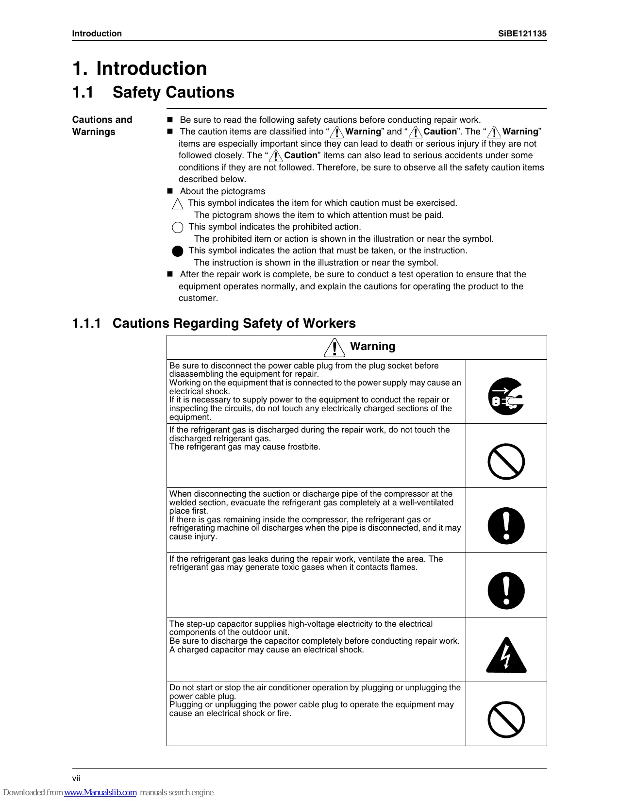
1.1.1 Cautions Regarding Safety of Workers
| Warning |
| Be sure to disconnect the power cable plug from the plug socket before disassembling the equipment for repair. Working on the equipment that is connected to the power supply may cause an electrical shock. If it is necessary to supply power to the equipment to conduct the repair or inspecting the circuits, do not touch any electrically charged sections of the equipment. | →BC |
| If the refrigerant gas is discharged during the repair work, do not touch the discharged refrigerant gas. The refrigerant gas may cause frostbite. | ∅ |
| When disconnecting the suction or discharge pipe of the compressor at the welded section, evacuate the refrigerant gas completely at a well-ventilated place first. If there is gas remaining inside the compressor, the refrigerant gas or refrigerating machine oil discharges when the pipe is disconnected, and it may cause injury. | ∅ |
| If the refrigerant gas leaks during the repair work, ventilate the area. The refrigerant gas may generate toxic gases when it contacts flames. | ∅ |
| The step-up capacitor supplies high-voltage electricity to the electrical components of the outdoor unit. Be sure to discharge the capacitor completely before conducting repair work. A charged capacitor may cause an electrical shock. | ∅ |
| Do not start or stop the air conditioner operation by plugging or unplugging the power cable plug. Plugging or unplugging the power cable plug to operate the equipment may cause an electrical shock or fire. | ∅ |
| Be sure to wear a safety helmet, gloves, and a safety belt when working at a high place (more than 2 m). Insufficient safety measures may cause a fall accident. | ∅ |
| In case of R-410A refrigerant models, be sure to use pipes, flare nuts and tools for the exclusive use of the R-410A refrigerant.
The use of materials for R-22 refrigerant models may cause a serious accident such as a damage of refrigerant cycle as well as an equipment failure. | ∅ |
| Caution |
| Do not repair the electrical components with wet hands. Working on the equipment with wet hands may cause an electrical shock. | |
| Do not clean the air conditioner by splashing water. Washing the unit with water may cause an electrical shock. | |
| Be sure to provide the grounding when repairing the equipment in a humid or wet place, to avoid electrical shocks. | |
| Be sure to turn off the power switch and unplug the power cable when cleaning the equipment. The internal fan rotates at a high speed, and may cause injury. | |
| Be sure to conduct repair work with appropriate tools. The use of inappropriate tools may cause injury. | |
| Be sure to check that the refrigerating cycle section has cooled down enough before conducting repair work. Working on the unit when the refrigerating cycle section is hot may cause burns. | |
| Use the welder in a well-ventilated place. Using the welder in an enclosed room may cause oxygen deficiency. | |
1.1.2 Cautions Regarding Safety of Users
| Warning |
| Be sure to use parts listed in the service parts list of the applicable model and appropriate tools to conduct repair work. Never attempt to modify the equipment.
The use of inappropriate parts or tools may cause an electrical shock, excessive heat generation or fire. | |
| If the power cable and lead wires have scratches or deteriorated, be sure to replace them.
Damaged cable and wires may cause an electrical shock, excessive heat generation or fire. | |
| Do not use a joined power cable or extension cable, or share the same power outlet with other electrical appliances, since it may cause an electrical shock, excessive heat generation or fire. | |
| Be sure to use an exclusive power circuit for the equipment, and follow the local technical standards related to the electrical equipment, the internal wiring regulations, and the instruction manual for installation when conducting electrical work.
Insufficient power circuit capacity and improper electrical work may cause an electrical shock or fire. | |
| Be sure to use the specified cable for wiring between the indoor and outdoor units. Make the connections securely and route the cable properly so that there is no force pulling the cable at the connection terminals.
Improper connections may cause excessive heat generation or fire. | |
| When wiring between the indoor and outdoor units, make sure that the terminal cover does not lift off or dismount because of the cable.
If the cover is not mounted properly, the terminal connection section may cause an electrical shock, excessive heat generation or fire. | |
| Do not damage or modify the power cable.
Damaged or modified power cable may cause an electrical shock or fire.
Placing heavy items on the power cable, and heating or pulling the power cable may damage the cable. | |
| Do not mix air or gas other than the specified refrigerant (R-410A / R-22) in the refrigerant system.
If air enters the refrigerating system, an excessively high pressure results, causing equipment damage and injury. | |
| If the refrigerant gas leaks, be sure to locate the leaking point and repair it before charging the refrigerant. After charging refrigerant, make sure that there is no refrigerant leak.
If the leaking point cannot be located and the repair work must be stopped, be sure to perform pump-down and close the service valve, to prevent the refrigerant gas from leaking into the room. The refrigerant gas itself is harmless, but it may generate toxic gases when it contacts flames, such as fan and other heaters, stoves and ranges. | |
| When relocating the equipment, make sure that the new installation site has sufficient strength to withstand the weight of the equipment.
If the installation site does not have sufficient strength and if the installation work is not conducted securely, the equipment may fall and cause injury. | |
| Check to make sure that the power cable plug is not dirty or loose, then insert the plug into a power outlet securely.
If the plug has dust or loose connection, it may cause an electrical shock or fire. | |
| Be sure to install the product correctly by using the provided standard installation frame.
Incorrect use of the installation frame and improper installation may cause the equipment to fall, resulting in injury. | For unitary type only |
| Be sure to install the product securely in the installation frame mounted on the window frame.
If the unit is not securely mounted, it may fall and cause injury. | For unitary type only |
| When replacing the coin battery in the remote controller, be sure to dispose of the old battery to prevent children from swallowing it.
If a child swallows the coin battery, see a doctor immediately. | |
| !Caution |
| Installation of a leakage breaker is necessary in some cases depending on the conditions of the installation site, to prevent electrical shocks. | ! |
| Do not install the equipment in a place where there is a possibility of combustible gas leaks.If the combustible gas leaks and remains around the unit, it may cause a fire. | ! |
| Check to see if the parts and wires are mounted and connected properly, and if the connections at the soldered or crimped terminals are secure.Improper installation and connections may cause excessive heat generation, fire or an electrical shock. | ! |
| If the installation platform or frame has corroded, replace it.Corroded installation platform or frame may cause the unit to fall, resulting in injury. | ! |
| Check the grounding, and repair it if the equipment is not properly grounded.Improper grounding may cause an electrical shock. | ! |
| Caution |
| Be sure to measure the insulation resistance after the repair, and make sure that the resistance is 1 MΩ or higher.
Faulty insulation may cause an electrical shock. | |
| Be sure to check the drainage of the indoor unit after the repair.
Faulty drainage may cause the water to enter the room and wet the furniture and floor. | |
| Do not tilt the unit when removing it.
The water inside the unit may spill and wet the furniture and floor. | |
| Be sure to install the packing and seal on the installation frame properly.
If the packing and seal are not installed properly, water may enter the room and wet the furniture and floor. | For unitary type only
! |
1.2 Used Icons
Icons are used to attract the attention of the reader to specific information. The meaning of each icon is described in the table below:
| Icon | Type of Information | Description |
| Note: | Note | A “note” provides information that is not indispensable, but may nevertheless be valuable to the reader, such as tips and tricks. |
| Caution | Caution | A “caution” is used when there is danger that the reader, through incorrect manipulation, may damage equipment, loose data, get an unexpected result or has to restart (part of) a procedure. |
| Warning | Warning | A “warning” is used when there is danger of personal injury. |
| Reference | Reference | A “reference” guides the reader to other places in this binder or in this manual, where he/she will find additional information on a specific topic. |
Part 1 List of Functions
- Cooling Only 2
1.1 Outdoor Unit 2
1.2 Indoor Unit 3
- Heat Pump 6
2.1 Outdoor Unit 6
2.2 Indoor Unit 7
1. Cooling Only
1.1 Outdoor Unit
| Category | Functions | 3MKS50E3V1B, 4MKS58E3V1B4MKS75F2V1B | 5MKS90E2V3B | Category | Functions | 3MKS50E3V1B, 4MKS58E3V1B4MKS75F2V1B | 5MKS90E2V3B |
| Basic Function | Inverter (with Inverter Power Control) | ● | ● | Health & Clean | Air-Purifying Filter | — | — |
| Operation Limit for Cooling (°CDB) | -10~46 | 10~46 | Photocatalytic Deodorizing Filter | — | — |
| Operation Limit for Heating (°CW B) | — | — | Air-Purifying Filter with Photocatalytic Deodorizing Function | — | — |
| PAM Control | ● | ● |
| Standby Electricity Saving | — | — | Titanium Apatite Photocatalytic Air-Purifying Filter | — | — |
| Compressor | Oval Scroll Compressor | — | — |
| Swing Compressor | ● | ● | Air Filter (Prefilter) | — | — |
| Rotary Compressor | — | — | Wipe-Clean Flat Panel | — | — |
| Reluctance DC Motor | ● | ● | Washable Grille | — | — |
| Comfortable Airflow | Power-Airflow Flap | — | — | MOLD PROOF Operation | — | — |
| Power-Airflow Dual Flaps | — | — | Good-Sleep Cooling Operation | — | — |
| Power-Airflow Diffuser | — | — | Timer | WEEKLY TIMER Operation | — | — |
| Wide-Angle Louvers | — | — | 24-Hour ON/OFF TIMER | — | — |
| Vertical Auto-Swing (Up and Down) | — | — | NIGHT SET Mode | — | — |
| Horizontal Auto-Swing (Right and Left) | — | — | Worry Free "Reliability & Durability" | Auto-Restart (after Power Failure) | — | — |
| 3-D Airflow | — | — | Self-Diagnosis (Digital, LED) Display | ● | ● |
| COMFORT AIRFLOW Operation | — | — | Wiring Error Check Function | ● | ● |
| Comfort Control | Auto Fan Speed | — | — | Anti-Corrosion Treatment of Outdoor Heat Exchanger | ● | ● |
| Indoor Unit Quiet Operation | — | — | Flexibility | Multi-Split / Split Type Compatible Indoor Unit | — | — |
| NIGHT QUIET Mode (Automatic) | ● | ● | H/P, C/O Compatible Indoor Unit | — | — |
| OUTDOOR UNIT QUIET Operation (Manual) | ● | ● | Flexible Power Supply Correspondence | — | — |
| 2-Area INTELLIGENT EYE Operation | — | — | High Ceiling Application | — | — |
| INTELLIGENT EYE Operation | — | — | Chargeless | ● | 65 m |
| Quick Warming Function (Preheating Operation) | — | — | Either Side Drain (Right or Left) | — | — |
| Hot-Start Function | — | — | Power Selection | — | — |
| Automatic Defrosting | — | — | Remote Control | 5-Room Centralized Controller (Option) | — | — |
| Operation | Automatic Operation | — | — |
| Program Dry Operation | — | — | Remote Control Adaptor (Normal Open Pulse Contact) (Option) | — | — |
| Fan Only | — | — |
| Lifestyle Convenience | New POWERFUL Operation (Non-Inverter) | — | — | Remote Control Adaptor (Normal Open Contact) (Option) | — | — |
| Inverter POWERFUL Operation | — | — | DIII-NET Compatible (Adaptor) (Option) | — | — |
| Priority-Room Setting | ● | ● | Remote Controller | Wireless (Option) | — | — |
| COOL / HEAT Mode Lock | — | — | Wired | — | — |
| HOME LEAVE Operation | — | — |
| ECONO Operation | — | — |
| Indoor Unit [ON/OFF] Button | — | — |
| Signal Receiving Sign | — | — |
| R/C with Back Light | — | — |
| Temperature Display | — | — |
Note: : Holding Functions
—: No Functions
1.2 Indoor Unit
| Category | Functions | FTXS25/35/42/50/21B | FTXS80/71GYIB | Category | Functions | FTXS25/35/42/50/21B | FTXS60/71GYIB |
| Basic Function | Inverter (with Inverter Power Control) | ● | ● | Health & Clean | Air-Purifying Filter | — | — |
| Operation Limit for Cooling (°CDB) | — | — | Photocatalytic Deodorizing Filter | — | — |
| Operation Limit for Heating (°CWB) | — | — | Air-Purifying Filter with Photocatalytic Deodorizing Function | — | — |
| PAM Control | — | — |
| Standby Electricity Saving | — | — | Titanium Apatite Photocatalytic Air-Purifying Filter | ● | ● |
| Compressor | Oval Scroll Compressor | — | — |
| Swing Compressor | — | — | Air Filter (Prefilter) | ● | ● |
| Rotary Compressor | — | — | Wipe-Clean Flat Panel | ● | ● |
| Reluctance DC Motor | — | — | Washable Grille | — | — |
| Comfortable Airflow | Power-Airflow Flap | — | — | MOLD PROOF Operation | — | — |
| Power-Airflow Dual Flaps | ● | ● | Good-Sleep Cooling Operation | — | — |
| Power-Airflow Diffuser | — | — | Timer | WEEKLY TIMER Operation | ● | ● |
| Wide-Angle Louvers | ● | ● | 24-Hour ON/OFF TIMER | ● | ● |
| Vertical Auto-Swing (Up and Down) | ● | ● | NIGHT SET Mode | ● | ● |
| Horizontal Auto-Swing (Right and Left) | ● | ● | Worry Free "Reliability & Durability" | Auto-Restart (after Power Failure) | ● | ● |
| 3-D Airflow | ● | ● | Self-Diagnosis (Digital, LED) Display | ● | ● |
| COMFORT AIRFLOW Operation | ● | ● | Wiring Error Check Function | — | — |
| Comfort Control | Auto Fan Speed | ● | ● | Anti-Corrosion Treatment of Outdoor Heat Exchanger | — | — |
| Indoor Unit Quiet Operation | ● | ● | Flexibility | Multi-Split / Split Type Compatible Indoor Unit | ● | ● |
| NIGHT QUIET Mode (Automatic) | — | — | H/P, C/O Compatible Indoor Unit | ● | ● |
| OUTDOOR UNIT QUIET Operation (Manual) | ● | ● | Flexible Power Supply Correspondence | — | — |
| 2-Area INTELLIGENT EYE Operation | ● | — | High Ceiling Application | — | — |
| INTELLIGENT EYE Operation | — | ● | Chargeless | — | — |
| Quick Warming Function (Preheating Operation) | — | — | Either Side Drain (Right or Left) | ● | ● |
| Hot-Start Function | — | — | Power Selection | — | — |
| Automatic Defrosting | — | — | Remote Control | 5-Room Centralized Controller (Option) | ● | ● |
| Operation | Automatic Operation | — | — | Remote Control Adaptor (Normal Open Pulse Contact) (Option) | ● | ● |
| Program Dry Operation | ● | ● |
| Fan Only | ● | ● | Remote Control Adaptor (Normal Open Contact) (Option) | ● | ● |
| Lifestyle Convenience | New POWERFUL Operation (Non-Inverter) | — | — | DIII-NET Compatible (Adaptor) (Option) | ● | ● |
| Inverter POWERFUL Operation | ● | ● | Remote Controller | Wireless | ● | ● |
| Priority-Room Setting | — | — | Wired (Option) | ● | ● |
| COOL / HEAT Mode Lock | — | — | | | | |
| HOME LEAVE Operation | — | — | | | | |
| ECONO Operation | ● | ● | | | | |
| Indoor Unit [ON/OFF] Button | ● | ● | | | | |
| Signal Receiving Sign | ● | ● | | | | |
| R/C with Back Light | — | — | | | | |
| Temperature Display | — | — | | | | |
Note: : Holding Functions
—: No Functions
| Category | Functions | FFQ25/35/50/60/BY1B | Category | Functions | FFQ25/35/50/60/BY1B |
| Basic Function | Inverter (with Inverter Power Control) | ● | Health & Clean | Air-Purifying Filter | — |
| Operation Limit for Cooling (°CDB) | — | Photocatalytic Deodorizing Filter | — |
| Operation Limit for Heating (°CWB) | — | Air-Purifying Filter with Photocatalytic Deodorizing Function | — |
| PAM Control | — |
| Standby Electricity Saving | — | Titanium Apatite Photocatalytic Air-Purifying Filter | — |
| Compressor | Oval Scroll Compressor | — |
| Swing Compressor | — | Longlife Filter | ● |
| Rotary Compressor | — | Wipe-Clean Flat Panel | — |
| Reluctance DC Motor | — | Washable Grille | ● |
| Comfortable Airflow | Power-Airflow Flap | — | Filter Cleaning Indicator | ● |
| Power-Airflow Dual Flaps | — | Self-Cleaning Decoration Panel (Option) | — |
| Power-Airflow Diffuser | — | MOLD PROOF Operation | — |
| Wide-Angle Louvers | — | Good-Sleep Cooling Operation | — |
| Vertical Auto-Swing (Up and Down) | ● | Timer | Schedule Timer Operation | ●★2 |
| Horizontal Auto-Swing (Right and Left) | — | 72-Hour ON/OFF TIMER | ●★1 |
| 3-D Airflow | — | NIGHT SET Mode | — |
| COMFORT AIRFLOW Operation | — | Worry Free "Reliability & Durability" | Auto-Restart (after Power Failure) | ● |
| Comfort Control | Auto Fan Speed | — | Self-Diagnosis (Digital, LED) Display | ● |
| Indoor Unit Quiet Operation | — | Wiring Error Check Function | — |
| NIGHT QUIET Mode (Automatic) | — | Anti-Corrosion Treatment of Outdoor Heat Exchanger | — |
| OUTDOOR UNIT QUIET Operation (Manual) | — | Flexibility | Multi-Split / Split Type Compatible Indoor Unit | ● |
| 2-Area INTELLIGENT EYE Operation | — | H/P, C/O Compatible Indoor Unit | ● |
| INTELLIGENT EYE Operation | — | Flexible Power Supply Correspondence | — |
| Quick Warming Function (Preheating Operation) | — | High Ceiling Application | — |
| Hot-Start Function | — | Chargeless | — |
| Automatic Defrosting | — | Either Side Drain (Right or Left) | — |
| Operation | Automatic Operation | — | Power Selection | — |
| Program Dry Operation | ● | Remote Control | 5-Room Centralized Controller (Option) | — |
| Fan Only | ● | Remote Control Adaptor (Normal Open Pulse Contact) (Option) | — |
| Lifestyle Convenience | New POWERFUL Operation (Non-Inverter) | — | Remote Control Adaptor (Normal Open Contact) (Option) | — |
| Inverter POWERFUL Operation | — |
| Priority-Room Setting | — | DIII-NET Compatible (Adaptor) (Option) | ● |
| COOL / HEAT Mode Lock | — | Remote Controller | Wireless (Option) | ● |
| HOME LEAVE Operation | — | Wired (Option) | ● |
| ECONO Operation | — | | | |
| Indoor Unit [ON/OFF] Button | ●★1 | | | |
| Signal Receiving Sign | ●★1 | | | |
| Temperature Display | — | | | |
Note: : Holding Functions
—: No Functions
1 : with wireless remote controller
2 : with wired remote controller
| Category | Functions | FHC35/50/60B/WY1B | FBDQ25B8V1FBQ35/50/60C8VEB | Category | Functions | FHC35/50/60B/WY1B | FBDQ25B8V1FBQ35/50/60C8VEB |
| Basic Function | Inverter (with Inverter Power Control) | ● | ● | Health & Clean | Air-Purifying Filter | — | — |
| Operation Limit for Cooling (°CDB) | — | — | Photocatalytic Deodorizing Filter | — | — |
| Operation Limit for Heating (°CWB) | — | — | Air-Purifying Filter with Photocatalytic Deodorizing Function | — | — |
| PAM Control | — | — |
| Standby Electricity Saving | — | — | Titanium Apatite Photocatalytic Air-Purifying Filter | — | — |
| Compressor | Oval Scroll Compressor | — | — |
| Swing Compressor | — | — | Longlife Filter | ● | ● |
| Rotary Compressor | — | — | Wipe-Clean Flat Panel | — | — |
| Reluctance DC Motor | — | — | Washable Grille | ● | — |
| Comfortable Airflow | Power-Airflow Flap | — | — | Filter Cleaning Indicator | ● | ● |
| Power-Airflow Dual Flaps | — | — | Self-Cleaning Decoration Panel (Option) | — | — |
| Power-Airflow Diffuser | — | — | MOLD PROOF Operation | — | — |
| Wide-Angle Louvers | — | — | Good-Sleep Cooling Operation | — | — |
| Vertical Auto-Swing (Up and Down) | ● | — | Timer | Schedule Timer Operation | ●★2 | ●★2 |
| Horizontal Auto-Swing (Right and Left) | — | — | 72-Hour ON/OFF TIMER | ●★1 | — |
| 3-D Airflow | — | — | NIGHT SET Mode | — | — |
| COMFORT AIRFLOW Operation | — | — | Worry Free "Reliability & Durability" | Auto-Restart (after Power Failure) | ● | ● |
| Comfort Control | Auto Fan Speed | — | — | Self-Diagnosis (Digital, LED) Display | ● | ● |
| Indoor Unit Quiet Operation | — | — | Wiring Error Check Function | — | — |
| NIGHT QUIET Mode (Automatic) | — | — | Anti-Corrosion Treatment of Outdoor Heat Exchanger | — | — |
| OUTDOOR UNIT QUIET Operation (Manual) | — | — | Flexibility | Multi-Split / Split Type Compatible Indoor Unit | ● | ● |
| 2-Area INTELLIGENT EYE Operation | — | — | H/P, C/O Compatible Indoor Unit | ● | ● |
| INTELLIGENT EYE Operation | — | — | Flexible Power Supply Correspondence | — | — |
| Quick Warming Function (Preheating Operation) | — | — | High Ceiling Application | ● | — |
| Hot-Start Function | — | — | Chargeless | — | — |
| Automatic Defrosting | — | — | Either Side Drain (Right or Left) | — | — |
| Operation | Automatic Operation | — | — | Power Selection | — | — |
| Program Dry Operation | ● | ● | Remote Control | 5-Room Centralized Controller (Option) | — | — |
| Fan Only | ● | ● | Remote Control Adaptor (Normal Open Pulse Contact) (Option) | — | — |
| Lifestyle Convenience | New POWERFUL Operation (Non-Inverter) | — | — |
| Inverter POWERFUL Operation | — | — | Remote Control Adaptor (Normal Open Contact) (Option) | — | — |
| Priority-Room Setting | — | — | DIII-NET Compatible (Adaptor) (Option) | ● | ● |
| COOL / HEAT Mode Lock | — | — | Remote Controller | Wireless (Option) | ● | — |
| HOME LEAVE Operation | — | — | Wired (Option) | ● | ● |
| ECONO Operation | — | — | | | | |
| Indoor Unit [ON/OFF] Button | ●★1 | — | | | | |
| Signal Receiving Sign | ●★1 | — | | | | |
| Temperature Display | — | — | | | | |
Note: : Holding Functions
—: No Functions
1 : with wireless remote controller
2 : with wired remote controller
2. Heat Pump
2.1 Outdoor Unit
| Category | Functions | 3MXS40K2V1B, 3MXS52E3V1B3MXS68G2V1B, 4MXS8F2V1B4MXS80E2V3B, 5MXS90E2V3B | Category | Functions | 3MXS40K2V1B, 3MXS52E3V1B3MXS68G2V1B, 4MXS8F2V1B4MXS80E2V3B, 5MXS90E2V3B |
| 4MXS80E2V3B, 5MXS90E2V3B |
| Basic Function | Inverter (with Inverter Power Control) | ● | ● | Health & Clean | Air-Purifying Filter | — | — |
| Operation Limit for Cooling (°CDB) | -10~46 | -10~46 | Photocatalytic Deodorizing Filter | — | — |
| Operation Limit for Heating (°CWB) | -15~15.5 | -15~15.5 | Air-Purifying Filter with Photocatalytic Deodorizing Function | — | — |
| PAM Control | ● | ● | Titanium Apatite Photocatalytic Air-Purifying Filter | — | — |
| Standby Electricity Saving | — | — |
| Compressor | Oval Scroll Compressor | — | — | Air Filter (Prefilter) | — | — |
| Swing Compressor | ● | ● | Wipe-Clean Flat Panel | — | — |
| Rotary Compressor | — | — | Washable Grille | — | — |
| Reluctance DC Motor | ● | ● | MOLD PROOF Operation | — | — |
| Comfortable Airflow | Power-Airflow Flap | — | — | Good-Sleep Cooling Operation | — | — |
| Power-Airflow Dual Flaps | — | — | Timer | WEEKLY TIMER Operation | — | — |
| Power-Airflow Diffuser | — | — | 24-Hour ON/OFF TIMER | — | — |
| Wide-Angle Louvers | — | — | NIGHT SET Mode | — | — |
| Vertical Auto-Swing (Up and Down) | — | — | Worry Free "Reliability & Durability" | Auto-Restart (after Power Failure) | — | — |
| Horizontal Auto-Swing (Right and Left) | — | — | Self-Diagnosis (Digital, LED) Display | ● | ● |
| 3-D Airflow | — | — | Wiring Error Check Function | ● | ● |
| COMFORT AIRFLOW Operation | — | — | Anti-Corrosion Treatment of Outdoor Heat Exchanger | ● | ● |
| Comfort Control | Auto Fan Speed | — | — | Flexibility | Multi-Split / Split Type Compatible Indoor Unit | — | — |
| Indoor Unit Quiet Operation | — | — | H/P, C/O Compatible Indoor Unit | — | — |
| NIGHT QUIET Mode (Automatic) | ● | ● | Flexible Power Supply Correspondence | — | — |
| OUTDOOR UNIT QUIET Operation (Manual) | ● | ● | High Ceiling Application | — | — |
| 2-Area INTELLIGENT EYE Operation | — | — | Chargeless | 30 m | 30 m |
| INTELLIGENT EYE Operation | — | — | Either Side Drain (Right or Left) | — | — |
| Quick Warming Function (Preheating Operation) | ● | ● | Power Selection | — | — |
| Hot-Start Function | — | — | Remote Control | 5-Room Centralized Controller (Option) | — | — |
| Automatic Defrosting | ● | ● |
| Operation | Automatic Operation | — | — | Remote Control Adaptor (Normal Open Pulse Contact) (Option) | — | — |
| Program Dry Operation | — | — |
| Fan Only | — | — | Remote Control Adaptor (Normal Open Contact) (Option) | — | — |
| Lifestyle Convenience | New POWERFUL Operation (Non-Inverter) | — | — |
| Inverter POWERFUL Operation | — | — | DIII-NET Compatible (Adaptor) (Option) | — | — |
| Priority-Room Setting | ● | ● | Remote Controller | Wireless (Option) | — | — |
| COOL / HEAT Mode Lock | ● | ● | Wired | — | — |
| HOME LEAVE Operation | — | — |
| ECONO Operation | — | — |
| Indoor Unit [ON/OFF] Button | — | — |
| Signal Receiving Sign | — | — |
| R/C with Back Light | — | — |
| Temperature Display | — | — |
Note: : Holding Functions
—: No Functions
2.2 Indoor Unit
| Category | Functions | FTXG25/35/60/71/BW(A) | Category | Functions | FTXG25/35/60/71/BW(A) |
| Basic Function | Inverter (with Inverter Power Control) | ● | Health & Clean | Air-Purifying Filter | — |
| Operation Limit for Cooling (°CDB) | — | Photocatalytic Deodorizing Filter | — |
| Operation Limit for Heating (°CWB) | — | Air-Purifying Filter with Photocatalytic Deodorizing Function | — |
| PAM Control | — | Titanium Apatite Photocatalytic Air-Purifying Filter | ● |
| Standby Electricity Saving | — |
| Compressor | Oval Scroll Compressor | — | Air Filter (Prefilter) | ● |
| Swing Compressor | — | Wipe-Clean Flat Panel | ● |
| Rotary Compressor | — | Washable Grille | — |
| Reluctance DC Motor | — | MOLD PROOF Operation | — |
| Comfortable Airflow | Power-Airflow Flap | — | Good-Sleep Cooling Operation | — |
| Power-Airflow Dual Flaps | ● | Timer | WEEKLY TIMER Operation | ● |
| Power-Airflow Diffuser | — | 24-Hour ON/OFF TIMER | ● |
| Wide-Angle Louvers | ● | NIGHT SET Mode | ● |
| Vertical Auto-Swing (Up and Down) | ● | Worry Free "Reliability & Durability" | Auto-Restart (after Power Failure) | ● |
| Horizontal Auto-Swing (Right and Left) | — | Self-Diagnosis (Digital, LED) Display | ● |
| 3-D Airflow | — | Wiring Error Check Function | — |
| COMFORT AIRFLOW Operation | ● | Anti-Corrosion Treatment of Outdoor Heat Exchanger | — |
| Comfort Control | Auto Fan Speed | ● |
| Indoor Unit Quiet Operation | ● | Flexibility | Multi-Split / Split Type Compatible Indoor Unit | ● |
| NIGHT QUIET Mode (Automatic) | — |
| OUTDOOR UNIT QUIET Operation (Manual) | ● | H/P, C/O Compatible Indoor Unit | — |
| INTELLIGENT EYE Operation | ● | Flexible Power Supply Correspondence | — |
| 2-Area INTELLIGENT EYE Operation | — | High Ceiling Application | — |
| Quick Warming Function (Preheating Operation) | — | Chargeless | — |
| Hot-Start Function | ● | Either Side Drain (Right or Left) | ● |
| Automatic Defrosting | — | Power Selection | — |
| Operation | Automatic Operation | ● | Remote Control | 5-Room Centralized Controller (Option) | ● |
| Program Dry Operation | ● |
| Fan Only | ● | Remote Control Adaptor (Normal Open Pulse Contact) (Option) | ● |
| Lifestyle Convenience | New POWERFUL Operation (Non-Inverter) | — | Remote Control Adaptor (Normal Open Contact) (Option) | ● |
| Inverter POWERFUL Operation | ● | DIII-NET Compatible (Adaptor) (Option) | ● |
| Priority-Room Setting | — | Remote Controller | Wireless | ● |
| COOL / HEAT Mode Lock | — | Wired (Option) | ● |
| HOME LEAVE Operation | — | | | |
| ECONO Operation | ● | | | |
| Indoor Unit [ON/OFF] Button | ● | | | |
| Signal Receiving Sign | ● | | | |
| Multi-Colored Indicator Lamp (Multi-Monitor Lamp) | ● | | | |
| R/C with Back Light | ● | | | |
| Temperature Display | — | | | |
Note: : Holding Functions
—: No Functions
| Category | Functions | FTXS20/25K2V1B | CTXS15/35K2V1B | Category | Functions | FTXS20/25K2V1B | CTXS15/35K2V1B |
| Basic Function | Inverter (with Inverter Power Control) | ● | ● | Health & Clean | Air-Purifying Filter | — | — |
| Operation Limit for Cooling (°CDB) | — | — | Photocatalytic Deodorizing Filter | — | — |
| Operation Limit for Heating (°CWB) | — | — | Air-Purifying Filter with Photocatalytic Deodorizing Function | — | — |
| PAM Control | — | — | Titanium Apatite Photocatalytic Air-Purifying Filter | ● | ● |
| Standby Electricity Saving | — | — |
| Compressor | Oval Scroll Compressor | — | — | Air Filter (Prefilter) | ● | ● |
| Swing Compressor | — | — | Wipe-Clean Flat Panel | ● | ● |
| Rotary Compressor | — | — | Washable Grille | — | — |
| Reluctance DC Motor | — | — | MOLD PROOF Operation | — | — |
| Comfortable Airflow | Power-Airflow Flap | ● | ● | Good-Sleep Cooling Operation | — | — |
| Power-Airflow Dual Flaps | — | — | Timer | WEEKLY TIMER Operation | ● | ● |
| Power-Airflow Diffuser | — | — | 24-Hour ON/OFF TIMER | ● | ● |
| Wide-Angle Louvers | ● | ● | NIGHT SET Mode | ● | ● |
| Vertical Auto-Swing (Up and Down) | ● | ● | Worry Free "Reliability & Durability" | Auto-Restart (after Power Failure) | ● | ● |
| Horizontal Auto-Swing (Right and Left) | — | — | Self-Diagnosis (Digital, LED) Display | ● | ● |
| 3-D Airflow | — | — | Wiring Error Check Function | — | — |
| COMFORT AIRFLOW Operation | ● | ● | Anti-Corrosion Treatment of Outdoor Heat Exchanger | — | — |
| Comfort Control | Auto Fan Speed | ● | ● |
| Indoor Unit Quiet Operation | ● | ● | Flexibility | Multi-Split / Split Type Compatible Indoor Unit | ● | — |
| NIGHT QUIET Mode (Automatic) | — | — |
| OUTDOOR UNIT QUIET Operation (Manual) | ● | ● | H/P, C/O Compatible Indoor Unit | — | — |
| INTELLIGENT EYE Operation | ● | ● | Flexible Power Supply Correspondence | — | — |
| 2-Area INTELLIGENT EYE Operation | — | — | High Ceiling Application | — | — |
| Quick Warming Function (Preheating Operation) | — | — | Chargeless | — | — |
| Hot-Start Function | ● | ● | Either Side Drain (Right or Left) | ● | ● |
| Automatic Defrosting | — | — | Power Selection | — | — |
| Operation | Automatic Operation | ● | ● | Remote Control | 5-Room Centralized Controller (Option) | ● | ● |
| Program Dry Operation | ● | ● |
| Fan Only | ● | ● | Remote Control Adaptor (Normal Open Pulse Contact) (Option) | ● | ● |
| Lifestyle Convenience | New POWERFUL Operation (Non-Inverter) | — | — | Remote Control Adaptor (Normal Open Contact) (Option) | ● | ● |
| Inverter POWERFUL Operation | ● | ● | DIII-NET Compatible (Adaptor) (Option) | ● | ● |
| Priority-Room Setting | — | — | Remote Controller | Wireless | ● | ● |
| COOL / HEAT Mode Lock | — | — | Wired (Option) | ● | ● |
| HOME LEAVE Operation | — | — | | | | |
| ECONO Operation | ● | ● | | | | |
| Indoor Unit [ON/OFF] Button | ● | ● | | | | |
| Signal Receiving Sign | ● | ● | | | | |
| Multi-Colored Indicator Lamp (Multi-Monitor Lamp) | — | — | | | | |
| R/C with Back Light | ● | ● | | | | |
| Temperature Display | — | — | | | | |
Note: : Holding Functions
—: No Functions
| Category | Functions | FTXS25/35/42/50/21B | FTXS6071GVB | Category | Functions | FTXS25/35/42/50/21B | FTXS6071GVB |
| Basic Function | Inverter (with Inverter Power Control) | ● | ● | Health & Clean | Air-Purifying Filter | — | — |
| Operation Limit for Cooling (°CDB) | — | — | Photocatalytic Deodorizing Filter | — | — |
| Operation Limit for Heating (°CW8) | — | — | Air-Purifying Filter with Photocatalytic Deodorizing Function | — | — |
| PAM Control | — | — | Titanium Apatite Photocatalytic Air-Purifying Filter | ● | ● |
| Standby Electricity Saving | — | — |
| Compressor | Oval Scroll Compressor | — | — | Air Filter (Prefilter) | ● | ● |
| Swing Compressor | — | — | Wipe-Clean Flat Panel | ● | ● |
| Rotary Compressor | — | — | Washable Grille | — | — |
| Reluctance DC Motor | — | — | MOLD PROOF Operation | — | — |
| Comfortable Airflow | Power-Airflow Flap | — | — | Good-Sleep Cooling Operation | — | — |
| Power-Airflow Dual Flaps | ● | ● | Timer | WEEKLY TIMER Operation | ● | ● |
| Power-Airflow Diffuser | — | — | 24-Hour ON/OFF TIMER | ● | ● |
| Wide-Angle Louvers | ● | ● | NIGHT SET Mode | ● | ● |
| Vertical Auto-Swing (Up and Down) | ● | ● | Worry Free "Reliability & Durability" | Auto-Restart (after Power Failure) | ● | ● |
| Horizontal Auto-Swing (Right and Left) | ● | ● | Self-Diagnosis (Digital, LED) Display | ● | ● |
| 3-D Airflow | ● | ● | Wiring Error Check Function | — | — |
| COMFORT AIRFLOW Operation | ● | ● | Anti-Corrosion Treatment of Outdoor Heat Exchanger | — | — |
| Comfort Control | Auto Fan Speed | ● | ● | Flexibility | Multi-Split / Split Type Compatible Indoor Unit | ● | ● |
| Indoor Unit Quiet Operation | ● | ● | H/P, C/O Compatible Indoor Unit | ● | ● |
| NIGHT QUIET Mode (Automatic) | — | — | Flexible Power Supply Correspondence | — | — |
| OUTDOOR UNIT QUIET Operation (Manual) | ● | ● | High Ceiling Application | — | — |
| 2-Area INTELLIGENT EYE Operation | ● | — | Chargeless | — | — |
| INTELLIGENT EYE Operation | — | ● | Either Side Drain (Right or Left) | ● | ● |
| Quick Warming Function (Preheating Operation) | — | — | Power Selection | — | — |
| Hot-Start Function | ● | ● | Remote Control | 5-Room Centralized Controller (Option) | ● | ● |
| Automatic Defrosting | — | — |
| Operation | Automatic Operation | ● | ● | Remote Control Adaptor (Normal Open Pulse Contact) (Option) | ● | ● |
| Program Dry Operation | ● | ● |
| Fan Only | ● | ● | Remote Control Adaptor (Normal Open Contact) (Option) | ● | ● |
| Lifestyle Convenience | New POWERFUL Operation (Non-Inverter) | — | — | DIII-NET Compatible (Adaptor) (Option) | ● | ● |
| Inverter POWERFUL Operation | ● | ● | Remote Controller | Wireless | ● | ● |
| Priority-Room Setting | — | — | Wired (Option) | ● | ● |
| COOL / HEAT Mode Lock | — | — | | | | |
| HOME LEAVE Operation | — | — | | | | |
| ECONO Operation | ● | ● | | | | |
| Indoor Unit [ON/OFF] Button | ● | ● | | | | |
| Signal Receiving Sign | ● | ● | | | | |
| Multi-Colored Indicator Lamp (Multi-Monitor Lamp) | — | — | | | | |
| R/C with Back Light | — | — | | | | |
| Temperature Display | — | — | | | | |
Note: : Holding Functions
—: No Functions
| Category | Functions | FVXG25/35/50K2V1B | FVXG25/35/50FV1B | Category | Functions | FVXG25/35/50K2V1B | FVXG25/35/50FV1B |
| Basic Function | Inverter (with Inverter Power Control) | ● | ● | Health & Clean | Air-Purifying Filter | — | — |
| Operation Limit for Cooling (°CDB) | — | — | Photocatalytic Deodorizing Filter | — | — |
| Operation Limit for Heating (°CWB) | — | — | Air-Purifying Filter with Photocatalytic Deodorizing Function | — | — |
| PAM Control | — | — | Titanium Apatite Photocatalytic Air-Purifying Filter | ● | ● |
| Standby Electricity Saving | — | — |
| Compressor | Oval Scroll Compressor | — | — | Air Filter (Prefilter) | ● | ● |
| Swing Compressor | — | — | Wipe-Clean Flat Panel | — | ● |
| Rotary Compressor | — | — | Washable Grille | — | — |
| Reluctance DC Motor | — | — | MOLD PROOF Operation | — | — |
| Comfortable Airflow | Power-Airflow Flap | — | — | Good-Sleep Cooling Operation | — | — |
| Power-Airflow Dual Flaps | — | — | Timer | WEEKLY TIMER Operation | ● | ● |
| Power-Airflow Diffuser | — | — | 24-Hour ON/OFF TIMER | ● | ● |
| Wide-Angle Louvers | ● | ● | NIGHT SET Mode | ● | ● |
| Vertical Auto-Swing (Up and Down) | ● | ● | Worry Free "Reliability & Durability" | Auto-Restart (after Power Failure) | ● | ● |
| Horizontal Auto-Swing (Right and Left) | — | — | Self-Diagnosis (Digital, LED) Display | ● | ● |
| 3-D Airflow | — | — | Wiring Error Check Function | — | — |
| COMFORT AIRFLOW Operation | — | — | Anti-Corrosion Treatment of Outdoor Heat Exchanger | — | — |
| Comfort Control | Auto Fan Speed | ● | ● | Flexibility | Multi-Split / Split Type Compatible Indoor Unit | ● | ● |
| Indoor Unit Quiet Operation | ● | ● | H/P, C/O Compatible Indoor Unit | — | ● |
| NIGHT QUIET Mode (Automatic) | — | — | Flexible Power Supply Correspondence | — | — |
| OUTDOOR UNIT QUIET Operation (Manual) | ● | ● | High Ceiling Application | — | — |
| 2-Area INTELLIGENT EYE Operation | — | — | Chargeless | — | — |
| INTELLIGENT EYE Operation | — | — | Either Side Drain (Right or Left) | — | — |
| Quick Warming Function (Preheating Operation) | — | — | Power Selection | — | — |
| Hot-Start Function | ● | ● | Remote Control | 5-Room Centralized Controller (Option) | ● | ● |
| Automatic Defrosting | — | — | Remote Control Adaptor (Normal Open Pulse Contact) (Option) | ● | ● |
| Operation | Automatic Operation | ● | ● | Remote Control Adaptor (Normal Open Contact) (Option) | ● | ● |
| RADIANT Operation | ● | — | DIII-NET Compatible (Adaptor) (Option) | ● | ● |
| Program Dry Operation | ● | ● | Remote Controller | Wireless | ● | ● |
| Fan Only | ● | ● | Wired (Option) | ● | — |
| Lifestyle Convenience | New POWERFUL Operation (Non-Inverter) | — | — | | | | |
| Inverter POWERFUL Operation | ● | ● | | | | |
| Priority-Room Setting | — | — | | | | |
| COOL / HEAT Mode Lock | — | — | | | | |
| HOME LEAVE Operation | — | — | | | | |
| ECONO Operation | ● | ● | | | | |
| Indoor Unit [ON/OFF] Button | ● | ● | | | | |
| Signal Receiving Sign | ● | ● | | | | |
| Multi-Colored Indicator Lamp (Multi-Monitor Lamp) | — | — | | | | |
| R/C with Back Light | ● | ● | | | | |
| Temperature Display | — | — | | | | |
Note: : Holding Functions
—: No Functions
| Category | Functions | FLXS25/35/60/80AVMB | FDXS25/35/60/75VMB | Category | Functions | FLXS25/35/60/80AVMB | FDXS25/35/60/75VMB |
| Basic Function | Inverter (with Inverter Power Control) | ● | ● | Health & Clean | Air-Purifying Filter | ● | — |
| Operation Limit for Cooling (°CDB) | — | — | Photocatalytic Deodorizing Filter | ● | — |
| Operation Limit for Heating (°CWB) | — | — | Air-Purifying Filter with Photocatalytic Deodorizing Function | — | — |
| PAM Control | — | — | Titanium Apatite Photocatalytic Air-Purifying Filter | — | — |
| Standby Electricity Saving | — | — |
| Compressor | Oval Scroll Compressor | — | — | Air Filter (Prefilter) | ● | ● |
| Swing Compressor | — | — | Wipe-Clean Flat Panel | — | — |
| Rotary Compressor | — | — | Washable Grille | — | — |
| Reluctance DC Motor | — | — | MOLD PROOF Operation | — | — |
| Comfortable Airflow | Power-Airflow Flap | — | — | Good-Sleep Cooling Operation | — | — |
| Power-Airflow Dual Flaps | — | — | Timer | WEEKLY TIMER Operation | — | — |
| Power-Airflow Diffuser | — | — | 24-Hour ON/OFF TIMER | ● | ● |
| Wide-Angle Louvers | — | — | NIGHT SET Mode | ● | ● |
| Vertical Auto-Swing (Up and Down) | ● | — | Worry Free "Reliability & Durability" | Auto-Restart (after Power Failure) | ● | ● |
| Horizontal Auto-Swing (Right and Left) | — | — | Self-Diagnosis (Digital, LED) Display | ● | ● |
| 3-D Airflow | — | — | Wiring Error Check Function | — | — |
| COMFORT AIRFLOW Operation | — | — | Anti-Corrosion Treatment of Outdoor Heat Exchanger | — | — |
| Comfort Control | Auto Fan Speed | ● | ● | Flexibility | Multi-Split / Split Type Compatible Indoor Unit | ● | ● |
| Indoor Unit Quiet Operation | ● | ● | H/P, C/O Compatible Indoor Unit | — | — |
| NIGHT QUIET Mode (Automatic) | — | — | Flexible Power Supply Correspondence | ● | ● |
| OUTDOOR UNIT QUIET Operation (Manual) | ● | ● | High Ceiling Application | — | — |
| 2-Area INTELLIGENT EYE Operation | — | — | Chargeless | — | — |
| INTELLIGENT EYE Operation | — | — | Either Side Drain (Right or Left) | — | — |
| Quick Warming Function (Preheating Operation) | — | — | Power Selection | — | — |
| Hot-Start Function | ● | ● | Remote Control | 5-Room Centralized Controller (Option) | ● | ● |
| Automatic Defrosting | — | — |
| Operation | Automatic Operation | ● | ● | Remote Control Adaptor (Normal Open Pulse Contact) (Option) | ● | ● |
| Program Dry Operation | ● | ● |
| Fan Only | ● | ● | Remote Control Adaptor (Normal Open Contact) (Option) | ● | ● |
| Lifestyle Convenience | New POWERFUL Operation (Non-Inverter) | — | — |
| Inverter POWERFUL Operation | ● | ● | DIII-NET Compatible (Adaptor) (Option) | ● | ● |
| Priority-Room Setting | — | — | Remote Controller | Wireless | ● | ● |
| COOL / HEAT Mode Lock | — | — | Wired (Option) | — | ● |
| HOME LEAVE Operation | ● | ● | | | | |
| ECONO Operation | — | — | | | | |
| Indoor Unit [ON/OFF] Button | ● | ● | | | | |
| Signal Receiving Sign | ● | ● | | | | |
| Multi-Colored Indicator Lamp (Multi-Monitor Lamp) | — | — | | | | |
| R/C with Back Light | — | — | | | | |
| Temperature Display | — | — | | | | |
Note: : Holding Functions
—: No Functions
| Category | Functions | FCQG35/50/60FVEB | FFQ25/35/50/60B9V1B | Category | Functions | FCQG35/50/60FVEB | FFQ25/35/50/60B9V1B |
| Basic Function | Inverter (with Inverter Power Control) | ● | ● | Health & Clean | Air-Purifying Filter | — | — |
| Operation Limit for Cooling (°CDB) | — | — | Photocatalytic Deodorizing Filter | — | — |
| Operation Limit for Heating (°CWB) | — | — | Air-Purifying Filter with Photocatalytic Deodorizing Function | — | — |
| PAM Control | — | — | Titanium Apatite Photocatalytic Air-Purifying Filter | — | — |
| Standby Electricity Saving | — | — |
| Compressor | Oval Scroll Compressor | — | — | Longlife Filter | ● | ● |
| Swing Compressor | — | — | Wipe-Clean Flat Panel | — | — |
| Rotary Compressor | — | — | Washable Grille | ● | ● |
| Reluctance DC Motor | — | — | Filter Cleaning Indicator | ● | ● |
| Comfortable Airflow | Power-Airflow Flap | — | — | Self-Cleaning Decoration Panel (Option) | ● | — |
| Power-Airflow Dual Flaps | — | — | MOLD PROOF Operation | — | — |
| Power-Airflow Diffuser | — | — | Good-Sleep Cooling Operation | — | — |
| Wide-Angle Louvers | — | — | Timer | Schedule Timer Operation | ●★2 | ●★2 |
| Vertical Auto-Swing (Up and Down) | ● | ● | 72-Hour ON/OFF TIMER | ●★1 | ●★1 |
| Horizontal Auto-Swing (Right and Left) | — | — | NIGHT SET Mode | — | — |
| 3-D Airflow | — | — | Worry Free "Reliability & Durability" | Auto-Restart (after Power Failure) | ● | ● |
| COMFORT AIRFLOW Operation | — | — | Self-Diagnosis (Digital, LED) Display | ● | ● |
| Comfort Control | Auto Fan Speed | — | — | Wiring Error Check Function | — | — |
| Indoor Unit Quiet Operation | — | — | Anti-Corrosion Treatment of Outdoor Heat Exchanger | — | — |
| NIGHT QUIET Mode (Automatic) | — | — | Flexibility | Multi-Split / Split Type Compatible Indoor Unit | ● | ● |
| OUTDOOR UNIT QUIET Operation (Manual) | — | — | H/P, C/O Compatible Indoor Unit | ● | ● |
| 2-Area INTELLIGENT EYE Operation | — | — | Flexible Power Supply Correspondence | — | — |
| INTELLIGENT EYE Operation | — | — | High Ceiling Application | — | — |
| Quick Warming Function (Preheating Operation) | — | — | Chargeless | — | — |
| Hot-Start Function | ● | ● | Either Side Drain (Right or Left) | — | — |
| Automatic Defrosting | — | — | Power Selection | — | — |
| Operation | Automatic Operation | ● | ● | Remote Control | 5-Room Centralized Controller (Option) | — | — |
| Program Dry Operation | ● | ● | Remote Control Adaptor (Normal Open Pulse Contact) (Option) | — | — |
| Fan Only | ● | ● |
| Lifestyle Convenience | New POWERFUL Operation (Non-Inverter) | — | — | Remote Control Adaptor (Normal Open Contact) (Option) | — | — |
| Inverter POWERFUL Operation | — | — | DIII-NET Compatible (Adaptor) (Option) | ● | ● |
| Priority-Room Setting | — | — | Remote Controller | Wireless (Option) | ● | ● |
| COOL / HEAT Mode Lock | — | — | Wired (Option) | ● | ● |
| HOME LEAVE Operation | — | — |
| ECONO Operation | — | — |
| Indoor Unit [ON/OFF] Button | ●★1 | ●★1 |
| Signal Receiving Sign | ●★1 | ●★1 |
| Temperature Display | — | — |
Note: : Holding Functions
—: No Functions
1 : with wireless remote controller
2 with wired remote controller
| Category | Functions | FHC35/50/60BWV1B | FDCB25B8V1FBC35/50/60C8VEB | Category | Functions | FHC35/50/60BWV1B | FDCB25B8V1FBC35/50/60C8VEB |
| Basic Function | Inverter (with Inverter Power Control) | ● | ● | Health & Clean | Air-Purifying Filter | — | — |
| Operation Limit for Cooling (°CDB) | — | — | Photocatalytic Deodorizing Filter | — | — |
| Operation Limit for Heating (°CWB) | — | — | Air-Purifying Filter with Photocatalytic Deodorizing Function | — | — |
| PAM Control | — | — | Titanium Apatite Photocatalytic Air-Purifying Filter | — | — |
| Standby Electricity Saving | — | — |
| Compressor | Oval Scroll Compressor | — | — | Longlife Filter | ● | ● |
| Swing Compressor | — | — | Wipe-Clean Flat Panel | — | — |
| Rotary Compressor | — | — | Washable Grille | ● | — |
| Reluctance DC Motor | — | — | Filter Cleaning Indicator | ● | ● |
| Comfortable Airflow | Power-Airflow Flap | — | — | Self-Cleaning Decoration Panel (Option) | — | — |
| Power-Airflow Dual Flaps | — | — | MOLD PROOF Operation | — | — |
| Power-Airflow Diffuser | — | — | Good-Sleep Cooling Operation | — | — |
| Wide-Angle Louvers | — | — | Timer | Schedule Timer Operation | ●★2 | ● |
| Vertical Auto-Swing (Up and Down) | ● | — | 72-Hour ON/OFF TIMER | ●★1 | — |
| Horizontal Auto-Swing (Right and Left) | — | — | NIGHT SET Mode | — | — |
| 3-D Airflow | — | — | Worry Free "Reliability & Durability" | Auto-Restart (after Power Failure) | ● | ● |
| COMFORT AIRFLOW Operation | — | — | Self-Diagnosis (Digital, LED) Display | ● | ● |
| Comfort Control | Auto Fan Speed | — | — | Wiring Error Check Function | — | — |
| Indoor Unit Quiet Operation | — | — | Anti-Corrosion Treatment of Outdoor Heat Exchanger | — | — |
| NIGHT QUIET Mode (Automatic) | — | — | Flexibility | Multi-Split / Split Type Compatible Indoor Unit | ● | ● |
| OUTDOOR UNIT QUIET Operation (Manual) | — | — | H/P, C/O Compatible Indoor Unit | ● | ● |
| 2-Area INTELLIGENT EYE Operation | — | — | Flexible Power Supply Correspondence | — | — |
| INTELLIGENT EYE Operation | — | — | High Ceiling Application | ● | — |
| Quick Warming Function (Preheating Operation) | — | — | Chargeless | — | — |
| Hot-Start Function | ● | ● | Either Side Drain (Right or Left) | — | — |
| Automatic Defrosting | — | — | Power Selection | — | — |
| Operation | Automatic Operation | ● | ● | Remote Control | 5-Room Centralized Controller (Option) | — | — |
| Program Dry Operation | ● | ● | Remote Control Adaptor (Normal Open Pulse Contact) (Option) | — | — |
| Fan Only | ● | ● |
| Lifestyle Convenience | New POWERFUL Operation (Non-Inverter) | — | — | Remote Control Adaptor (Normal Open Contact) (Option) | — | — |
| Inverter POWERFUL Operation | — | — | DIII-NET Compatible (Adaptor) (Option) | ● | ● |
| Priority-Room Setting | — | — | Remote Controller | Wireless (Option) | ● | — |
| COOL / HEAT Mode Lock | — | — | Wired (Option) | ● | ● |
| HOME LEAVE Operation | — | — | | | | |
| ECONO Operation | — | — | | | | |
| Indoor Unit [ON/OFF] Button | ●★1 | — | | | | |
| Signal Receiving Sign | ●★1 | — | | | | |
| Temperature Display | — | — | | | | |
Note: : Holding Functions
—: No Functions
1 : with wireless remote controller
2 : with wired remote controller
Part 2
Specifications
- Cooling Only 15
1.1 Outdoor Unit 15
1.2 Indoor Unit 17
- Heat Pump 22
2.1 Outdoor Unit 22
2.2 Indoor Unit 25
1. Cooling Only
1.1 Outdoor Unit
50 Hz, 230 V
| Model | 3MKS50E3V1B | 4MKS58E3V1B |
| Casing Color | Ivory White | Ivory White |
| Compressor | Type | Hermetically Sealed Swing Type | Hermetically Sealed Swing Type |
| Model | 2YC36BXD | 2YC36BXD |
| Motor Output | W | 1,100 | 1,100 |
| Refrigerant Oil | Model | FVC50K | FVC50K |
| Charge | L | 0.65 | 0.65 |
| Refrigerant | Type | R-410A | R-410A |
| Charge | kg | 2.0 | 2.0 |
| Airflow Rate | H | m³/min | 45 | 45 |
| L | 45 | 45 |
| H | cfm | 1,589 | 1,589 |
| L | 1,589 | 1,589 |
| Fan | Type | Propeller | Propeller |
| Motor Output | W | 53 | 53 |
| Running Current | A | H: 0.33 / L: 0.33 | H: 0.33 / L: 0.33 |
| Power Consumption | W | H: 43 / L: 43 | H: 43 / L: 43 |
| Starting Current | A | 5.3 | 6.7 |
| Dimensions (H × W × D) | mm | 735 × 936 × 300 | 735 × 936 × 300 |
| Packaged Dimensions (H × W × D) | mm | 797 × 992 × 390 | 797 × 992 × 390 |
| Weight (Mass) | kg | 49 | 49 |
| Gross Weight (Gross Mass) | kg | 56 | 56 |
| Sound Pressure Level | dB(A) | 46 | 46 |
| Sound Power Level | dB | 59 | 59 |
| Piping Connection | Liquid | mm | φ 6.4 × 3 | φ 6.4 × 4 |
| Gas | mm | φ 9.5 × 3 | φ 9.5 × 2, φ 12.7 × 2 |
| Drain | mm | φ 18.0 | φ 18.0 |
| Heat Insulation | Both Liquid and Gas Pipes | Both Liquid and Gas Pipes |
| No. of Wiring Connection | 3 for Power Supply, 4 for Interunit Wiring | 3 for Power Supply, 4 for Interunit Wiring |
| Max. Interunit Piping Length | m | 50 (for Total of Each Room) | 50 (for Total of Each Room) |
| m | 25 (for One Room) | 25 (for One Room) |
| Amount of Additional Charge | g/m | Chargeless | Chargeless |
| Max. Installation Height Difference | m | 15 (between Indoor Unit and Outdoor Unit) | 15 (between Indoor Unit and Outdoor Unit) |
| m | 15 (between Indoor Units) | 15 (between Indoor Units) |
| Drawing No. | 3D054330#1 | 3D054329#1 |
Note:
The data are based on the conditions shown in the table below.
| Cooling | Piping Length |
| Indoor; 27°CDB / 19°CWB | 7.5 m |
| Outdoor; 35°CDB |
Conversion Formulae
kcal/h = kW × 860
Btu/h = kW × 3412
cfm = m^3 /min× 35.3
50 Hz, 230 V
| Model | 4MKS75F2V1B | 5MKS90E2V3B |
| Casing Color | Ivory White | Ivory White |
| Compressor | Type | Hermetically Sealed Swing Type | Hermetically Sealed Swing Type |
| Model | 2YC45DXD | 2YC63BXD |
| Motor Output | W | 1,380 | 1,920 |
| Refrigerant Oil | Model | FVC50K | FVC50K |
| Charge | L | 0.65 | 0.75 |
| Refrigerant | Type | R-410A | R-410A |
| Charge | kg | 2.3 | 2.95 |
| Airflow Rate | H | m³/min | 52.7 | 54.5 |
| M | 49.4 | — |
| L | 43.5 | 46 |
| H | cfm | 1,861 | 1,924 |
| M | 1,744 | — |
| L | 1,536 | 1,624 |
| Fan | Type | Propeller | Propeller |
| Motor Output | W | 53 | 66 |
| Running Current | A | H: 0.20 / M: 0.16 / L: 0.10 | H: 0.97 / L: 0.69 |
| Power Consumption | W | H: 70 / M: 58 / L: 36 | H: 86 / L: 55 |
| Starting Current | A | 6.2 | 11.4 |
| Dimensions (H × W × D) | mm | 735 × 936 × 300 | 770 × 900 × 320 |
| Packaged Dimensions (H × W × D) | mm | 797 × 992 × 390 | 900 × 925 × 390 |
| Weight (Mass) | kg | 57 | 69 |
| Gross Weight (Gross Mass) | kg | 61 | 78 |
| Sound Pressure Level | dB(A) | 48 | 48 |
| Sound Power Level | dB | 61 | 62 |
| Piping Connection | Liquid | mm | φ 6.4 × 4 | φ 6.4 × 5 |
| Gas | mm | φ 9.5 × 2, φ 12.7 × 1, φ 15.9 × 1 | φ 9.5 × 2, φ 12.7 × 1, φ 15.9 × 2 |
| Drain | mm | φ 18.0 | φ 25.0 |
| Heat Insulation | Both Liquid and Gas Pipes | Both Liquid and Gas Pipes |
| No. of Wiring Connection | 3 for Power Supply, 4 for Interunit Wiring | 3 for Power Supply, 4 for Interunit Wiring |
| Max. Interunit Piping Length | m | 60 (for Total of Each Room) | 75 (for Total of Each Room) |
| m | 25 (for One Room) | 25 (for One Room) |
| Amount of Additional Charge | g/m | Chargeless | 20 (65 m or more) |
| Max. Installation Height Difference | m | 15 (between Indoor Unit and Outdoor Unit) | 15 (between Indoor Unit and Outdoor Unit) |
| m | 15 (between Indoor Units) | 7.5 (between Indoor Units) |
| Drawing No. | 3D056453 | 3D063120 |
Note:
The data are based on the conditions shown in the table below.
Conversion Formulae
| Cooling | Piping Length |
| Indoor; 27°CDB / 19°CWB | 5 m (4MKS75F2V1B) |
| Outdoor; 35°CDB | 7.5 m (5MKS90E2V3B) |
kcal/h - kW × 860
Rt / h = kW× 3412
cfm = m^3 /min× 35.3
1.2 Indoor Unit
Wall Mounted Type
50 Hz, 220 - 230 - 240 V
| Model | FTXS25J2V1B | FTXS35J2V1B |
| Rated Capacity | 2.5 kW Class | 3.5 kW Class |
| Front Panel Color | White | White |
| Airflow Rate | H | m³/min (cfm) | 10.8 (381) | 11.4 (403) |
| M | 7.9 (279) | 8.7 (307) |
| L | 5.2 (184) | 5.8 (205) |
| SL | 3.7 (131) | 4.4 (155) |
| Fan | Type | Cross Flow Fan | Cross Flow Fan |
| Motor Output | W | 23 | 23 |
| Speed | Steps | 5 Steps, Quiet, Auto | 5 Steps, Quiet, Auto |
| Air Direction Control | Right, Left, Horizontal, Downward | Right, Left, Horizontal, Downward |
| Air Filter | Removable / Washable / Mildew Proof | Removable / Washable / Mildew Proof |
| Running Current (Rated) | A | 0.09 - 0.08 - 0.08 | 0.12 - 0.12 - 0.11 |
| Power Consumption (Rated) | W | 18 - 18 - 18 | 26 - 26 - 26 |
| Power Factor (Rated) | % | 90.9 - 97.8 - 93.8 | 98.5 - 94.2 - 98.5 |
| Temperature Control | Microcomputer Control | Microcomputer Control |
| Dimensions (H × W × D) | mm | 295 × 800 × 215 | 295 × 800 × 215 |
| Packaged Dimensions (H × W × D) | mm | 289 × 870 × 366 | 289 × 870 × 366 |
| Weight (Mass) | kg | 9 | 10 |
| Gross Weight (Gross Mass) | kg | 13 | 14 |
| Sound Pressure Level | H / M / L / SL | dB(A) | 41 / 33 / 25 / 22 | 45 / 37 / 29 / 23 |
| Sound Power Level | dB | 57 | 61 |
| Heat Insulation | Both Liquid and Gas Pipes | Both Liquid and Gas Pipes |
| Piping Connection | Liquid | mm | φ 6.4 | φ 6.4 |
| Gas | mm | φ 9.5 | φ 9.5 |
| Drain | mm | φ 18.0 | φ 18.0 |
| Drawing No. | 3D070570A | 3D070571A |
| Model | FTXS42J2V1B | FTXS50J2V1B |
| Rated Capacity | 4.2 kW Class | 5.0 kW Class |
| Front Panel Color | White | White |
| Airflow Rate | H | m3/min (cfm) | 11.3 (399) | 11.6 (410) |
| M | 9.0 (318) | 9.2 (325) |
| L | 6.8 (240) | 7.0 (247) |
| SL | 5.9 (208) | 6.0 (212) |
| Fan | Type | Cross Flow Fan | Cross Flow Fan |
| Motor Output | W | 23 | 23 |
| Speed | Steps | 5 Steps, Quiet, Auto | 5 Steps, Quiet, Auto |
| Air Direction Control | Right, Left, Horizontal, Downward | Right, Left, Horizontal, Downward |
| Air Filter | Removable / Washable / Mildew Proof | Removable / Washable / Mildew Proof |
| Running Current (Rated) | A | 0.11 - 0.11 - 0.11 | 0.12 - 0.12 - 0.11 |
| Power Consumption (Rated) | W | 24 - 24 - 24 | 26 - 26 - 26 |
| Power Factor (Rated) | % | 99.2 - 94.9 - 90.9 | 98.5 - 94.2 - 98.5 |
| Temperature Control | Microcomputer Control | Microcomputer Control |
| Dimensions (H × W × D) | mm | 295 × 800 × 215 | 295 × 800 × 215 |
| Packaged Dimensions (H × W × D) | mm | 289 × 870 × 366 | 289 × 870 × 366 |
| Weight (Mass) | kg | 10 | 10 |
| Gross Weight (Gross Mass) | kg | 14 | 14 |
| Sound Pressure Level | H / M / L / SL | dB(A) | 45 / 39 / 33 / 30 | 46 / 40 / 34 / 31 |
| Sound Power Level | dB | 61 | 62 |
| Heat Insulation | Both Liquid and Gas Pipes | Both Liquid and Gas Pipes |
| Piping Connection | Liquid | mm | φ 6.4 | φ 6.4 |
| Gas | mm | φ 9.5 | φ 12.7 |
| Drain | mm | φ 18.0 | φ 18.0 |
| Drawing No. | 3D070572A | 3D070573A |
Conversion Formulae
kcal/h = kW × 860
Btu/h = kW × 3412
cm = m^3 /min× 35.3
50 Hz, 220 - 230 - 240 V
| Model | FTXS60GV1B | FTXS71GV1B |
| Rated Capacity | 6.0 kW Class | 7.1 kW Class |
| Front Panel Color | White | White |
| Airflow Rate | H | m3/min (cfm) | 16.0 (565) | 17.2 (607) |
| M | 13.5 (477) | 14.5 (512) |
| L | 11.3 (399) | 11.5 (406) |
| SL | 10.1 (357) | 10.5 (371) |
| Fan | Type | Cross Flow Fan | Cross Flow Fan |
| Motor Output | W | 43 | 43 |
| Speed | Steps | 5 Steps, Quiet, Auto | 5 Steps, Quiet, Auto |
| Air Direction Control | Right, Left, Horizontal, Downward | Right, Left, Horizontal, Downward |
| Air Filter | Removable / Washable / Mildew Proof | Removable / Washable / Mildew Proof |
| Running Current (Rated) | A | 0.19 - 0.18 - 0.17 | 0.21 - 0.20 - 0.19 |
| Power Consumption (Rated) | W | 40 - 40 - 40 | 45 - 45 - 45 |
| Power Factor (Rated) | % | 95.7 - 96.6 - 98.0 | 97.4 - 97.8 - 98.7 |
| Temperature Control | Microcomputer Control | Microcomputer Control |
| Dimensions (H × W × D) | mm | 290 × 1,050 × 250 | 290 × 1,050 × 250 |
| Packaged Dimensions (H × W × D) | mm | 361 × 1,145 × 364 | 361 × 1,145 × 364 |
| Weight (Mass) | kg | 12 | 12 |
| Gross Weight (Gross Mass) | kg | 18 | 18 |
| Sound Pressure Level | H / M / L / SL | dB(A) | 45 / 41 / 36 / 33 | 46 / 42 / 37 / 34 |
| Sound Power Level | dB | 61 | 62 |
| Heat Insulation | Both Liquid and Gas Pipes | Both Liquid and Gas Pipes |
| Piping Connection | Liquid | mm | φ 6.4 | φ 6.4 |
| Gas | mm | φ 12.7 | φ 15.9 |
| Drain | mm | φ 18.0 | φ 18.0 |
| Drawing No. | 3D065735A | 3D065737A |
Conversion Formulae
kcal/h = kW × 860
Btu/m = kW × 3412
cfm = m³/min × 35.3
Ceiling Mounted Cassette Type
50 Hz, 230 V
| Model | FFQ25B9V1B | FFQ35B9V1B |
| Rated Capacity | 2.5 kW Class | 3.5 kW Class |
| Decoration Panel | Model | BYFQ60B8W1 | BYFQ60B8W1 |
| Color | White | White |
| Dimensions (H × W × D) | mm | 55 × 700 × 700 | 55 × 700 × 700 |
| Weight (Mass) | kg | 2.7 | 2.7 |
| Airflow Rate | H | m³/min (cfm) | 9.0 (318) | 10.0 (353) |
| L | 6.5 (230) | 6.5 (230) |
| Fan | Type | Turbo Fan | Turbo Fan |
| Motor Output | W | 55 | 55 |
| Speed | Steps | 2 Steps | 2 Steps |
| Air Direction Control | Horizontal, Downward | Horizontal, Downward |
| Running Current (Rated) | A | 0.37 | 0.40 |
| Power Consumption (Rated) | W | 73 | 84 |
| Power Factor (Rated) | % | 85.8 | 91.3 |
| Temperature Control | Microcomputer Control | Microcomputer Control |
| Dimensions (H × W × D) ★ | mm | 260 (286) × 575 × 575 | 260 (286) × 575 × 575 |
| Packaged Dimensions (H × W × D) | mm | 370 × 687 × 674 | 370 × 687 × 674 |
| Weight (Mass) | kg | 17.5 | 17.5 |
| Gross Weight (Gross Mass) | kg | 21 | 21 |
| Sound Pressure Level | H / L | dB(A) | 29.5 / 24.5 | 32.0 / 25.0 |
| Sound Power Level | dB | 46.5 | 49.0 |
| Heat Insulation | Both Liquid and Gas Pipes | Both Liquid and Gas Pipes |
| Piping Connection | Liquid | mm | φ 6.4 | φ 6.4 |
| Gas | mm | φ 9.5 | φ 9.5 |
| Drain | mm | VP20 (O.D. φ 26 / I.D. φ 20) | VP20 (O.D. φ 26 / I.D. φ 20) |
| Drawing No. | 3D060406 | 3D060408 |
| Model | FFQ50B9V1B | FFQ60B9V1B |
| Rated Capacity | 5.0 kW Class | 6.0 kW Class |
| Decoration Panel | Model | BYFQ60B8W1 | BYFQ60B8W1 |
| Color | White | White |
| Dimensions (H × W × D) | mm | 55 × 700 × 700 | 55 × 700 × 700 |
| Weight (Mass) | kg | 2.7 | 2.7 |
| Airflow Rate | H | m³/min (cfm) | 12.0 (424) | 15.5 (530) |
| L | 8.0 (283) | 10.0 (353) |
| Fan | Type | Turbo Fan | Turbo Fan |
| Motor Output | W | 55 | 55 |
| Speed | Steps | 2 Steps | 2 Steps |
| Air Direction Control | Horizontal, Downward | Horizontal, Downward |
| Running Current (Rated) | A | 0.49 | 0.61 |
| Power Consumption (Rated) | W | 97 | 120 |
| Power Factor (Rated) | % | 86.1 | 85.5 |
| Temperature Control | Microcomputer Control | Microcomputer Control |
| Dimensions (H × W × D) ★ | mm | 260 (286) × 575 × 575 | 260 (286) × 575 × 575 |
| Packaged Dimensions (H × W × D) | mm | 370 × 687 × 674 | 370 × 687 × 674 |
| Weight (Mass) | kg | 17.5 | 17.5 |
| Gross Weight (Gross Mass) | kg | 21 | 21 |
| Sound Pressure Level | H / L | dB(A) | 36.0 / 27.0 | 41.0 / 32.0 |
| Sound Power Level | dB | 53.0 | 58.0 |
| Heat Insulation | Both Liquid and Gas Pipes | Both Liquid and Gas Pipes |
| Piping Connection | Liquid | mm | φ 6.4 | φ 6.4 |
| Gas | mm | φ 12.7 | φ 12.7 |
| Drain | mm | VP20 (O.D. φ 26 / I.D. φ 20) | VP20 (O.D. φ 26 / I.D. φ 20) |
| Drawing No. | 3D060410 | 3D040431 |
★():dimension including control box
Conversion Formulae
kcal/h = kW × 860
Btu/h = kW × 3412
cfm = m^3 /min× 35.3
Ceiling Suspended Type
50 Hz, 220 - 230 - 240 V
| Model | FHQ35BWV1B | FHQ50BWV1B |
| Rated Capacity | 3.5 kW Class | 5.0 kW Class |
| Panel Color | White | White |
| Airflow Rate | H | m³/min | 13.0 (459) | 13.0 (459) |
| L | 10.0 (353) | 10.0 (353) |
| Fan | Type | Sirocco Fan | Sirocco Fan |
| Motor Output | W | 62 | 62 |
| Speed | Steps | 2 Steps | 2 Steps |
| Air Direction Control | Right, Left, Horizontal, Downward | Right, Left, Horizontal, Downward |
| Air Filter | Removable / Washable / Mildew Proof | Removable / Washable / Mildew Proof |
| Temperature Control | Microcomputer Control | Microcomputer Control |
| Dimensions (H × W × D) | mm | 195 × 960 × 680 | 195 × 960 × 680 |
| Packaged Dimensions (H × W × D) | mm | 279 × 1,046 × 818 | 279 × 1,046 × 818 |
| Weight (Mass) | kg | 24 | 25 |
| Gross Weight (Gross Mass) | kg | 31 | 32 |
| Sound Pressure Level | H / L | dB(A) | 37 / 32 | 38 / 33 |
| Sound Power Level | dB | 53 | 54 |
| Heat Insulation | Both Liquid and Gas Pipes | Both Liquid and Gas Pipes |
| Piping Connection | Liquid | mm | φ 6.4 | φ 6.4 |
| Gas | mm | φ 9.5 | φ 12.7 |
| Drain | mm | VP20 (O.D. φ 26 / I.D. φ 20) | VP20 (O.D. φ 26 / I.D. φ 20) |
| Drawing No. | 3D075708 | 3D075709 |
| Model | FHQ60B WV1B |
| Rated Capacity | 6.0 kW Class |
| Panel Color | White |
| Airflow Rate | H | m3/min | 17.0 (600) |
| L | 13.0 (459) |
| Fan | Type | Sirocco Fan |
| Motor Output | W | 62 |
| Speed | Steps | 2 Steps |
| Air Direction Control | Right, Left, Horizontal, Downward |
| Air Filter | Removable / Washable / Mildew Proof |
| Temperature Control | Microcomputer Control |
| Dimensions (H × W × D) | mm | 195 × 1,160 × 680 |
| Packaged Dimensions (H × W × D) | mm | 279 × 1,246 × 818 |
| Weight (Mass) | kg | 27 |
| Gross Weight (Gross Mass) | kg | 35 |
| Sound Pressure Level | H / L | dB(A) | 39 / 33 |
| Sound Power Level | dB | 55 |
| Heat Insulation | Both Liquid and Gas Pipes |
| Piping Connection | Liquid | mm | φ 6.4 |
| Gas | mm | φ 12.7 |
| Drain | mm | VP20 (O.D. φ 26 / I.D. φ 20) |
| Drawing No. | 3D075710 |
Conversion Formulae
kcal/h = kW × 860
Btu/h = kW × 3412
cfm = m^3 /min× 35.3
Ceiling Mounted Built-in Type
50 Hz, 230 V
50 Hz, 220 - 230 - 240 V /
60 Hz, 220 V
| Model | FDBQ25B8V1 | FBQ35C8VEB |
| Rated Capacity | 2.5 kW Class | 3.5 kW Class |
| Decoration Panel | Model | — | BYBS45DJW1 |
| Color | — | White |
| Dimensions (H × W × D) | — | 55 × 800 × 500 |
| Weight (Mass) | kg | — | 3.5 |
| Airflow Rate | H | m³/min | 6.5 | 16.0 |
| L | 5.2 | 11.0 |
| Fan | Type | Sirocco Fan | Sirocco Fan |
| Motor Output | W | 10 | 140 |
| Speed | Steps | 2 Steps | 2 Steps |
| Air Filter | Resin net with mold resistance | Resin net with mold resistance |
| Dimensions (H × W × D) | mm | 230 × 652 × 502 | 300 × 700 × 700 |
| Packaged Dimensions (H × W × D) | mm | 301 × 753 × 584 | 325 × 920 × 900 |
| Weight (Mass) | kg | 17 | 25 |
| Gross Weight (Gross Mass) | kg | 18 | 28 |
| Sound Pressure Level | H / L | dB(A) | 35 / 28 | 37 / 29 |
| Sound Power Level | H / L | dB | 55 / 49 | 63 / — |
| Heat Insulation | — | Both Liquid and Gas Pipes |
| Piping Connection | Liquid | mm | φ 6.35 | φ 6.35 (Flare) |
| Gas | mm | φ 9.52 | φ 9.52 (Flare) |
| Drain | mm | O.D. φ 27.2 | VP25 (O.D. φ 32 / I.D. φ 25) |
| Model | FBQ50C8VEB | FBQ60C8VEB |
| Rated Capacity | 5.0 kW Class | 6.0 kW Class |
| Decoration Panel | Model | BYBS45DJW1 | BYBS71DJW1 |
| Color | White | White |
| Dimensions (H × W × D) | 55 × 800 × 500 | 55 × 1,100 × 500 |
| Weight (Mass) | kg | 3.5 | 4.5 |
| Airflow Rate | H | m³/min | 16.0 | 18.0 |
| L | 11.0 | 15.0 |
| Fan | Type | Sirocco Fan | Sirocco Fan |
| Motor Output | W | 140 | 350 |
| Speed | Steps | 2 Steps | 2 Steps |
| Air Filter | Resin net with mold resistance | Resin net with mold resistance |
| Dimensions (H × W × D) | mm | 300 × 700 × 700 | 300 × 1,000 × 700 |
| Packaged Dimensions (H × W × D) | mm | 355 × 920 × 900 | 355 × 1,220 × 900 |
| Weight (Mass) | kg | 25 | 34 |
| Gross Weight (Gross Mass) | kg | 28 | 41 |
| Sound Pressure Level | H / L | dB(A) | 37 / 29 | 37 / 29 |
| Sound Power Level | H / L | dB | 63 / — | 57 / — |
| Heat Insulation | Both Liquid and Gas Pipes | Both Liquid and Gas Pipes |
| Piping Connection | Liquid | mm | φ 6.35 (Flare) | φ 6.35 (Flare) |
| Gas | mm | φ 12.7 (Flare) | φ 12.7 (Flare) |
| Drain | mm | VP25 (O.D. φ 32 / I.D. φ 25) | VP25 (O.D. φ 32 / I.D. φ 25) |
Conversion Formulae
kcal/h = kW × 860
Btu/h = kw × 3412 ft/min
cfm = m^3 /min× 35.3
2. Heat Pump
2.1 Outdoor Unit
50 Hz, 230 V
| Model | 3MXS40K2V1B | 3MXS52E3V1B |
| Cooling | Heating | Cooling | Heating |
| Casing Color | Ivory White | Ivory White |
| Compressor | Type | Hermetically Sealed Swing Type | Hermetically Sealed Swing Type |
| Model | 2YC36BXD | 2YC36BXD |
| Motor Output | W | 1,100 | 1,100 |
| Refrigerant Oil | Model | FVC50K | FVC50K |
| Charge | L | 0.65 | 0.65 |
| Refrigerant | Type | R-410A | R-410A |
| Charge | kg | 2.0 | 2.0 |
| Airflow Rate | H | m³/min | 45 | 45 | 45 | 45 |
| L | 41 | 41 | 45 | 41 |
| H | cfm | 1,589 | 1,589 | 1,589 | 1,589 |
| L | 1,448 | 1,448 | 1,589 | 1,448 |
| Fan | Type | Propeller | Propeller |
| Motor Output | W | 53 | 53 |
| Running Current | A | H: 0.33 / L: 0.29 | H: 0.33 / L: 0.29 |
| Power Consumption | W | H: 43 / L: 34 | H: 43 / L: 34 |
| Starting Current | A | 4.0 | 6.2 |
| Dimensions (H × W × D) | mm | 735 × 936 × 300 | 735 × 936 × 300 |
| Packaged Dimensions (H × W × D) | mm | 797 × 992 × 390 | 797 × 992 × 390 |
| Weight (Mass) | kg | 49 | 49 |
| Gross Weight (Gross Mass) | kg | 56 | 56 |
| Sound Pressure Level | dB(A) | 46 | 47 | 46 | 47 |
| Sound Power Level | dB | 59 | 60 | 59 | 60 |
| Piping Connection | Liquid | mm | φ 6.4 × 3 | φ 6.4 × 3 |
| Gas | mm | φ 9.5 × 3 | φ 9.5 × 2, φ 12.7 × 1 |
| Drain | mm | φ 18.0 | φ 18.0 |
| Heat Insulation | Both Liquid and Gas Pipes | Both Liquid and Gas Pipes |
| No. of Wiring Connection | 3 for Power Supply, 4 for Interunit Wiring | 3 for Power Supply, 4 for Interunit Wiring |
| Max. Interunit Piping Length | m | 50 (for Total of Each Room) | 50 (for Total of Each Room) |
| m | 25 (for One Room) | 25 (for One Room) |
| Amount of Additional Charge | g/m | 20 (30 m or more) | 20 (30 m or more) |
| Max. Installation Height Difference | m | 15 (between Indoor Unit and Outdoor Unit) | 15 (between Indoor Unit and Outdoor Unit) |
| m | 7.5 (between Indoor Units) | 7.5 (between Indoor Units) |
| Drawing No. | 3D074741 | 3D054327#1 |
Note:
The data are based on the conditions shown in the table below.
| Cooling | Heating | Piping Length |
| Indoor; 27°CDB / 19°CWB
Outdoor; 35°CDB | Indoor; 20°CDB
Outdoor; 7°CDB / 6°CWB | 5 m (3MXS40K2V1B)
7.5 m (3MXS52E3V1B) |
Conversion Formulae
kcal / h = kW× 860
Btu/h = kW × 3412
cfm = m^3 /min× 35.3
50 Hz, 230 V
| Model | 3MXS68G2V1B | 4MXS68F2V1B |
| Cooling | Heating | Cooling | Heating |
| Casing Color | Ivory White | Ivory White |
| Compressor | Type | Hermetically Sealed Swing Type | Hermetically Sealed Swing Type |
| Model | 2YC45DXD | 2YC45DXD |
| Motor Output | W | 1,380 | 1,380 |
| Refrigerant Oil | Model | FVC50K | FVC50K |
| Charge | L | 0.65 | 0.65 |
| Refrigerant | Type | R-410A | R-410A |
| Charge | kg | 2.59 | 2.6 |
| Airflow Rate | H | m³/min | 52.7 | 46.4 | 52.7 | 46.4 |
| M | 49.4 | 44.5 | 49.4 | 44.5 |
| L | 43.5 | 16.3 | 43.5 | 16.3 |
| H | cfm | 1,861 | 1,638 | 1,861 | 1,638 |
| M | 1,744 | 1,571 | 1,744 | 1,571 |
| L | 1,536 | 576 | 1,536 | 576 |
| Fan | Type | Propeller | Propeller |
| Motor Output | W | 53 | 53 |
| Running Current | A | H: 0.20 / M: 0.16 / L: 0.10 | H: 0.16 / M: 0.14 / L: 0.03 | H: 0.20 / M: 0.16 / L: 0.10 | H: 0.16 / M: 0.14 / L: 0.03 |
| Power Consumption | W | H: 70 / M: 58 / L: 36 | H: 55 / M: 48 / L: 10 | H: 70 / M: 58 / L: 36 | H: 55 / M: 48 / L: 10 |
| Starting Current | A | 6.2 | 6.2 |
| Dimensions (H × W × D) | mm | 735 × 936 × 300 | 735 × 936 × 300 |
| Packaged Dimensions (H × W × D) | mm | 797 × 992 × 390 | 797 × 992 × 390 |
| Weight (Mass) | kg | 58 | 58 |
| Gross Weight (Gross Mass) | kg | 63 | 63 |
| Sound Pressure Level | dB(A) | 48 | 49 | 48 | 49 |
| Sound Power Level | dB | 61 | — | 61 | — |
| Piping Connection | Liquid | mm | φ 6.4 × 3 | φ 6.4 × 4 |
| Gas | mm | φ 9.5 × 1, φ 12.7 × 2 | φ 9.5 × 2, φ 12.7 × 2 |
| Drain | mm | φ 18.0 | φ 18.0 |
| Heat Insulation | Both Liquid and Gas Pipes | Both Liquid and Gas Pipes |
| No. of Wiring Connection | 3 for Power Supply, 4 for Interunit Wiring | 3 for Power Supply, 4 for Interunit Wiring |
| Max. Interunit Piping Length | m | 50 (for Total of Each Room) | 60 (for Total of Each Room) |
| m | 25 (for One Room) | 25 (for One Room) |
| Amount of Additional Charge | g/m | 20 (30 m or more) | 20 (30 m or more) |
| Max. Installation Height Difference | m | 15 (between Indoor Unit and Outdoor Unit) | 15 (between Indoor Unit and Outdoor Unit) |
| m | 7.5 (between Indoor Units) | 7.5 (between Indoor Units) |
| Drawing No. | 3D058720A | 3D056404 |
Note:
The data are based on the conditions shown in the table below.
| Cooling | Heating | Piping Length |
| Indoor; 27°CDB / 19°CWB
Outdoor; 35°CDB | Indoor; 20°CDB
Outdoor; 7°CDB / 6°CWB | 5 m |
Conversion Formulae
kcal/h = kW × 860
Btu/h = kW × 3412
cfm = m^3 /min× 35.3
50 Hz, 230 V
| Model | 4MXS80E2V3B | 5MXS90E2V3B |
| Cooling | Heating | Cooling | Heating |
| Casing Color | Ivory White | Ivory White |
| Compressor | Type | Hermetically Sealed Swing Type | Hermetically Sealed Swing Type |
| Model | 2YC63BXD | 2YC63BXD |
| Motor Output | W | 1,920 | 1,920 |
| Refrigerant Oil | Model | FVC50K | FVC50K |
| Charge | L | 0.75 | 0.75 |
| Refrigerant | Type | R-410A | R-410A |
| Charge | kg | 2.99 | 2.99 |
| Airflow Rate | H | m³/min | 54.5 | 46.0 | 57.1 | 52.5 |
| M | — | — | 54.5 | — |
| L | 46 | 14.7 | 46.0 | 14.7 |
| H | cfm | 1,924 | 1,624 | 2,016 | 1,854 |
| M | — | — | 1,924 | — |
| L | 1,624 | 519 | 1,624 | 519 |
| Fan | Type | Propeller | Propeller |
| Motor Output | W | 66 | 66 |
| Running Current | A | H: 0.97 / L: 0.69 | H: 0.69 / L: 0.05 | H: 1.02 / M: 0.97 / L: 0.69 | H: 0.90 / L: 0.05 |
| Power Consumption | W | H: 86 / L: 55 | H: 55 / L: 9 | H: 95 / M: 86 / L: 55 | H: 78 / L: 9 |
| Starting Current | A | 9.7 | 11.8 |
| Dimensions (H × W × D) | mm | 770 × 900 × 320 | 770 × 900 × 320 |
| Packaged Dimensions (H × W × D) | mm | 900 × 925 × 390 | 900 × 925 × 390 |
| Weight (Mass) | kg | 72 | 73 |
| Gross Weight (Gross Mass) | kg | 80 | 80 |
| Sound Pressure Level | dB(A) | 48 | 49 | 52 | 52 |
| Sound Power Level | dB | 60 | — | 66 | — |
| Piping Connection | Liquid | mm | φ 6.4 × 4 | φ 6.4 × 5 |
| Gas | mm | φ 9.5 × 1, φ 12.7 × 1, φ 15.9 × 2 | φ 9.5 × 2, φ 12.7 × 1, φ 15.9 × 2 |
| Drain | mm | φ 25.0 | φ 25.0 |
| Heat Insulation | Both Liquid and Gas Pipes | Both Liquid and Gas Pipes |
| No. of Wiring Connection | 3 for Power Supply, 4 for Interunit Wiring | 3 for Power Supply, 4 for Interunit Wiring |
| Max. Interunit Piping Length | m | 70 (for Total of Each Room) | 75 (for Total of Each Room) |
| m | 25 (for One Room) | 25 (for One Room) |
| Amount of Additional Charge | g/m | 20 (30 m or more) | 20 (30 m or more) |
| Max. Installation Height Difference | m | 15 (between Indoor Unit and Outdoor Unit) | 15 (between Indoor Unit and Outdoor Unit) |
| m | 7.5 (between Indoor Units) | 7.5 (between Indoor Units) |
| Drawing No. | 3D063118 | 3D063119 |
Note:
The data are based on the conditions shown in the table below.
| Cooling | Heating | Piping Length |
| Indoor; 27°CDB / 19°CWB
Outdoor; 35°CDB | Indoor; 20°CDB
Outdoor; 7°CDB / 6°CWB | 7.5 m |
Conversion Formulae
kcal/h = kW × 860
Btu/h = kW × 3412
cfm = m^3 /min× 35.3
2.2 Indoor Unit
Wall Mounted Type
50 Hz, 220 - 230 - 240 V
| Model | FTXG25JV1BW | FTXG25JV1BA |
| Cooling | Heating | Cooling | Heating |
| Rated Capacity | 2.5 kW Class | 2.5 kW Class |
| Front Panel Color | White | Silver |
| Airflow Rate | H | m3/min (cfm) | 8.8 (311) | 9.6 (339) | 8.8 (311) | 9.6 (339) |
| M | 6.8 (240) | 7.9 (279) | 6.8 (240) | 7.9 (279) |
| L | 4.7 (166) | 6.2 (219) | 4.7 (166) | 6.2 (219) |
| SL | 3.8 (134) | 5.4 (191) | 3.8 (134) | 5.4 (191) |
| Fan | Type | Cross Flow Fan | Cross Flow Fan |
| Motor Output | W | 29 | 29 |
| Speed | Steps | 5 Steps, Quiet, Auto | 5 Steps, Quiet, Auto |
| Air Direction Control | Right, Left, Horizontal, Downward | Right, Left, Horizontal, Downward |
| Air Filter | Removable / Washable / Mildew Proof | Removable / Washable / Mildew Proof |
| Running Current (Rated) | A | 0.09 - 0.08 - 0.08 | 0.12 - 0.11 - 0.11 | 0.09 - 0.08 - 0.08 | 0.12 - 0.11 - 0.11 |
| Power Consumption (Rated) | W | 18 - 18 - 18 | 24 - 24 - 24 | 18 - 18 - 18 | 24 - 24 - 24 |
| Power Factor (Rated) | % | 90.9 - 97.8 - 93.8 | 90.9 - 94.9 - 90.9 | 90.9 - 97.8 - 93.8 | 90.9 - 94.9 - 90.9 |
| Temperature Control | Microcomputer Control | Microcomputer Control |
| Dimensions (H × W × D) | mm | 295 × 915 × 155 | 295 × 915 × 155 |
| Packaged Dimensions (H × W × D) | mm | 285 × 1,003 × 377 | 285 × 1,003 × 377 |
| Weight (Mass) | kg | 11 | 11 |
| Gross Weight (Gross Mass) | kg | 15 | 16 |
| Sound Pressure Level | H / M / L / SL | dB(A) | 38 / 32 / 25 / 22 | 39 / 34 / 28 / 25 | 38 / 32 / 25 / 22 | 39 / 34 / 28 / 25 |
| Sound Power Level | dB | 54 | 55 | 54 | 55 |
| Heat Insulation | Both Liquid and Gas Pipes | Both Liquid and Gas Pipes |
| Piping Connection | Liquid | mm | φ 6.4 | φ 6.4 |
| Gas | mm | φ 9.5 | φ 9.5 |
| Drain | mm | φ 16.0 or φ 18.0 | φ 16.0 or φ 18.0 |
| Drawing No. | 3D066165A | 3D066436A |
| Model | FTXG35JV1BW | FTXG35JV1BA |
| Cooling | Heating | Cooling | Heating |
| Rated Capacity | 3.5 kW Class | 3.5 kW Class |
| Front Panel Color | White | Silver |
| Airflow Rate | H | m³/min (cfm) | 10.1 (357) | 10.8 (381) | 10.1 (357) | 10.8 (381) |
| M | 7.3 (258) | 8.6 (304) | 7.3 (258) | 8.6 (304) |
| L | 4.6 (162) | 6.4 (226) | 4.6 (162) | 6.4 (226) |
| SL | 3.9 (138) | 5.6 (198) | 3.9 (138) | 5.6 (198) |
| Fan | Type | Cross Flow Fan | Cross Flow Fan |
| Motor Output | W | 29 | 29 |
| Speed | Steps | 5 Steps, Quiet, Auto | 5 Steps, Quiet, Auto |
| Air Direction Control | Right, Left, Horizontal, Downward | Right, Left, Horizontal, Downward |
| Air Filter | Removable / Washable / Mildew Proof | Removable / Washable / Mildew Proof |
| Running Current (Rated) | A | 0.13 - 0.12 - 0.12 | 0.16 - 0.15 - 0.14 | 0.13 - 0.12 - 0.12 | 0.16 - 0.15 - 0.14 |
| Power Consumption (Rated) | W | 26 - 26 - 26 | 32 - 32 - 32 | 26 - 26 - 26 | 32 - 32 - 32 |
| Power Factor (Rated) | % | 90.9 - 94.2 - 90.3 | 90.9 - 92.8 - 95.2 | 90.9 - 94.2 - 90.3 | 90.9 - 92.8 - 95.2 |
| Temperature Control | Microcomputer Control | Microcomputer Control |
| Dimensions (H × W × D) | mm | 295 × 915 × 155 | 295 × 915 × 155 |
| Packaged Dimensions (H × W × D) | mm | 285 × 1,003 × 377 | 285 × 1,003 × 377 |
| Weight (Mass) | kg | 11 | 11 |
| Gross Weight (Gross Mass) | kg | 15 | 16 |
| Sound Pressure Level | H / M / L / SL | dB(A) | 42 / 34 / 26 / 23 | 42 / 36 / 29 / 26 | 42 / 34 / 26 / 23 | 42 / 36 / 29 / 26 |
| Sound Power Level | dB | 58 | 58 | 58 | 58 |
| Heat Insulation | Both Liquid and Gas Pipes | Both Liquid and Gas Pipes |
| Piping Connection | Liquid | mm | φ 6.4 | φ 6.4 |
| Gas | mm | φ 9.5 | φ 9.5 |
| Drain | mm | φ 16.0 or φ 18.0 | φ 16.0 or φ 18.0 |
| Drawing No. | 3D066437A | 3D066438B |
Conversion Formulae
kcal/h = kW × 860
Btu/h = kW × 3412
cfm = m^3 /min× 35.3
50 Hz, 220 - 230 - 240 V
| Model | FTXG50JV1BW | FTXG50JV1BA |
| Cooling | Heating | Cooling | Heating |
| Rated Capacity | 5.0 kW Class | 5.0 kW Class |
| Front Panel Color | White | Silver |
| Airflow Rate | H | m3/min (cfm) | 10.3 (364) | 11.4 (402) | 10.3 (364) | 11.4 (402) |
| M | 8.5 (300) | 9.8 (346) | 8.5 (300) | 9.8 (346) |
| L | 6.7 (237) | 8.1 (286) | 6.7 (237) | 8.1 (286) |
| SL | 5.7 (201) | 7.1 (251) | 5.7 (201) | 7.1 (251) |
| Fan | Type | Cross Flow Fan | Cross Flow Fan |
| Motor Output | W | 40 | 40 |
| Speed | Steps | 5 Steps, Quiet, Auto | 5 Steps, Quiet, Auto |
| Air Direction Control | Right, Left, Horizontal, Downward | Right, Left, Horizontal, Downward |
| Air Filter | Removable / Washable / Mildew Proof | Removable / Washable / Mildew Proof |
| Running Current (Rated) | A | 0.16 - 0.15 - 0.14 | 0.19 - 0.18 - 0.17 | 0.16 - 0.15 - 0.14 | 0.19 - 0.18 - 0.17 |
| Power Consumption (Rated) | W | 32 - 32 - 32 | 38 - 38 - 38 | 32 - 32 - 32 | 38 - 38 - 38 |
| Power Factor (Rated) | % | 90.9 - 92.8 - 95.2 | 90.9 - 91.8 - 93.1 | 90.9 - 92.8 - 95.2 | 90.9 - 91.8 - 93.1 |
| Temperature Control | Microcomputer Control | Microcomputer Control |
| Dimensions (H × W × D) | mm | 295 × 915 × 155 | 295 × 915 × 155 |
| Packaged Dimensions (H × W × D) | mm | 285 × 1,003 × 377 | 285 × 1,003 × 377 |
| Weight (Mass) | kg | 11 | 11 |
| Gross Weight (Gross Mass) | kg | 15 | 16 |
| Sound Pressure Level | H / M / L / SL | dB(A) | 44 / 40 / 35 / 32 | 44 / 40 / 35 / 32 | 44 / 40 / 35 / 32 | 44 / 40 / 35 / 32 |
| Sound Power Level | dB | 60 | 60 | 60 | 60 |
| Heat Insulation | Both Liquid and Gas Pipes | Both Liquid and Gas Pipes |
| Piping Connection | Liquid | mm | φ 6.4 | φ 6.4 |
| Gas | mm | φ 12.7 | φ 12.7 |
| Drain | mm | φ 18.0 | φ 18.0 |
| Drawing No. | 3D071585 | 3D072083A |
| Model | CTXS15K2V1B | FTXS20K2V1B |
| Cooling | Heating | Cooling | Heating |
| Rated Capacity | 1.5 kW Class | 2.0 kW Class |
| Front Panel Color | White | White |
| Airflow Rate | H | m3/min (cfm) | 7.9 (279) | 9.0 (318) | 8.8 (311) | 9.5 (335) |
| M | 6.3 (222) | 7.5 (265) | 6.7 (237) | 7.8 (275) |
| L | 4.7 (166) | 6.0 (212) | 4.7 (166) | 6.0 (212) |
| SL | 3.9 (138) | 4.3 (152) | 3.9 (138) | 4.3 (152) |
| Fan | Type | Cross Flow Fan | Cross Flow Fan |
| Motor Output | W | 16 | 16 |
| Speed | Steps | 5 Steps, Quiet, Auto | 5 Steps, Quiet, Auto |
| Air Direction Control | Right, Left, Horizontal, Downward | Right, Left, Horizontal, Downward |
| Air Filter | Removable / Washable / Mildew Proof | Removable / Washable / Mildew Proof |
| Running Current (Rated) | A | 0.19 - 0.18 - 0.17 | 0.19 - 0.18 - 0.17 | 0.19 - 0.18 - 0.17 | 0.19 - 0.18 - 0.17 |
| Power Consumption (Rated) | W | 40 - 40 - 40 | 40 - 40 - 40 | 40 - 40 - 40 | 40 - 40 - 40 |
| Power Factor (Rated) | % | 95.7 - 96.6 - 98.0 | 95.7 - 96.6 - 98.0 | 95.7 - 96.6 - 98.0 | 95.7 - 96.6 - 98.0 |
| Temperature Control | Microcomputer Control | Microcomputer Control |
| Dimensions (H × W × D) | mm | 289 × 780 × 215 | 289 × 780 × 215 |
| Packaged Dimensions (H × W × D) | mm | 274 × 850 × 346 | 274 × 850 × 346 |
| Weight (Mass) | kg | 8 | 8 |
| Gross Weight (Gross Mass) | kg | 12 | 12 |
| Sound Pressure Level | H / M / L / SL | dB(A) | 37 / 31 / 25 / 21 | 38 / 33 / 28 / 21 | 40 / 32 / 24 / 19 | 40 / 34 / 27 / 19 |
| Sound Power Level | dB | 53 | 54 | 56 | 56 |
| Heat Insulation | Both Liquid and Gas Pipes | Both Liquid and Gas Pipes |
| Piping Connection | Liquid | mm | φ 6.4 | φ 6.4 |
| Gas | mm | φ 9.5 | φ 9.5 |
| Drain | mm | φ 18.0 | φ 18.0 |
| Drawing No. | 3D074531 | 3D074533 |
Conversion Formulae
kcal / h = kW× 860
[ \text{cfm} = \frac{\text{m}^3}{\text{min}} \times 35.3 ]
50 Hz, 220 - 230 - 240 V
| Model | FTXS25K2V1B | CTXS35K2V1B |
| Cooling | Heating | Cooling | Heating |
| Rated Capacity | 2.5 kW Class | 3.5 kW Class |
| Front Panel Color | White | White |
| Airflow Rate | H | m3/min (cfm) | 9.1 (321) | 10.0 (353) | 9.2 (325) | 10.1 (357) |
| M | 7.0 (247) | 8.0 (282) | 7.2 (254) | 8.1 (286) |
| L | 5.0 (177) | 6.0 (212) | 5.2 (184) | 6.3 (222) |
| SL | 3.9 (138) | 4.3 (152) | 3.9 (138) | 4.3 (152) |
| Fan | Type | Cross Flow Fan | Cross Flow Fan |
| Motor Output | W | 16 | 16 |
| Speed | Steps | 5 Steps, Quiet, Auto | 5 Steps, Quiet, Auto |
| Air Direction Control | Right, Left, Horizontal, Downward | Right, Left, Horizontal, Downward |
| Air Filter | Removable / Washable / Mildew Proof | Removable / Washable / Mildew Proof |
| Running Current (Rated) | A | 0.19 - 0.18 - 0.17 | 0.19 - 0.18 - 0.17 | 0.19 - 0.18 - 0.17 | 0.19 - 0.18 - 0.17 |
| Power Consumption (Rated) | W | 40 - 40 - 40 | 40 - 40 - 40 | 40 - 40 - 40 | 40 - 40 - 40 |
| Power Factor (Rated) | % | 95.7 - 96.6 - 98.0 | 95.7 - 96.6 - 98.0 | 95.7 - 96.6 - 98.0 | 95.7 - 96.6 - 98.0 |
| Temperature Control | Microcomputer Control | Microcomputer Control |
| Dimensions (H × W × D) | mm | 289 × 780 × 215 | 289 × 780 × 215 |
| Packaged Dimensions (H × W × D) | mm | 274 × 850 × 346 | 274 × 850 × 346 |
| Weight (Mass) | kg | 8 | 8 |
| Gross Weight (Gross Mass) | kg | 12 | 12 |
| Sound Pressure Level | H / M / L / SL | dB(A) | 41 / 33 / 25 / 19 | 41 / 34 / 27 / 19 | 42 / 35 / 28 / 21 | 41 / 36 / 30 / 21 |
| Sound Power Level | dB | 57 | 57 | 58 | 57 |
| Heat Insulation | Both Liquid and Gas Pipes | Both Liquid and Gas Pipes |
| Piping Connection | Liquid | mm | φ 6.4 | φ 6.4 |
| Gas | mm | φ 9.5 | φ 9.5 |
| Drain | mm | φ 18.0 | φ 18.0 |
| Drawing No. | 3D074534 | 3D074535 |
| Model | FTXS25J2V1B | FTXS35J2V1B |
| Cooling | Heating | Cooling | Heating |
| Rated Capacity | 2.5 kW Class | 3.5 kW Class |
| Front Panel Color | White | White |
| Airflow Rate | H | m³/min (cfm) | 10.8 (381) | 11.9 (420) | 11.4 (403) | 12.4 (438) |
| M | 7.9 (279) | 9.1 (321) | 8.7 (307) | 9.5 (335) |
| L | 5.2 (184) | 6.4 (226) | 5.8 (205) | 6.8 (240) |
| SL | 3.7 (131) | 5.9 (208) | 4.4 (155) | 6.0 (212) |
| Fan | Type | Cross Flow Fan | Cross Flow Fan |
| Motor Output | W | 23 | 23 |
| Speed | Steps | 5 Steps, Quiet, Auto | 5 Steps, Quiet, Auto |
| Air Direction Control | Right, Left, Horizontal, Downward | Right, Left, Horizontal, Downward |
| Air Filter | Removable / Washable / Mildew Proof | Removable / Washable / Mildew Proof |
| Running Current (Rated) | A | 0.09 - 0.08 - 0.08 | 0.10 - 0.10 - 0.09 | 0.12 - 0.12 - 0.11 | 0.13 - 0.13 - 0.12 |
| Power Consumption (Rated) | W | 18 - 18 - 18 | 21 - 21 - 21 | 26 - 26 - 26 | 28 - 28 - 28 |
| Power Factor (Rated) | % | 90.9 - 97.8 - 93.8 | 95.5 - 91.3 - 97.2 | 98.5 - 94.2 - 98.5 | 97.9 - 93.6 - 97.2 |
| Temperature Control | Microcomputer Control | Microcomputer Control |
| Dimensions (H × W × D) | mm | 295 × 800 × 215 | 295 × 800 × 215 |
| Packaged Dimensions (H × W × D) | mm | 289 × 870 × 366 | 289 × 870 × 366 |
| Weight (Mass) | kg | 9 | 10 |
| Gross Weight (Gross Mass) | kg | 13 | 14 |
| Sound Pressure Level | H / M / L / SL | dB(A) | 41 / 33 / 25 / 22 | 42 / 35 / 28 / 25 | 45 / 37 / 29 / 23 | 45 / 39 / 29 / 26 |
| Sound Power Level | dB | 57 | 58 | 61 | 61 |
| Heat Insulation | Both Liquid and Gas Pipes | Both Liquid and Gas Pipes |
| Piping Connection | Liquid | mm | φ 6.4 | φ 6.4 |
| Gas | mm | φ 9.5 | φ 9.5 |
| Drain | mm | φ 18.0 | φ 18.0 |
| Drawing No. | 3D070565A | 3D070566A |
Conversion Formulae
kcal / h = kW× 860
[ \text{cfm} = \frac{\text{m}^3}{\text{min}} \times 35.3 ]
50 Hz, 220 - 230 - 240 V
| Model | FTXS42J2V1B | FTXS50J2V1B |
| Cooling | Heating | Cooling | Heating |
| Rated Capacity | 4.2 kW Class | 5.0 kW Class |
| Front Panel Color | White | White |
| Airflow Rate | H | m3/min (cfm) | 11.3 (399) | 12.2 (431) | 11.6 (410) | 12.1 (427) |
| M | 9.0 (318) | 9.7 (343) | 9.2 (325) | 9.8 (346) |
| L | 6.8 (240) | 7.3 (258) | 7.0 (247) | 7.6 (268) |
| SL | 5.9 (208) | 6.4 (228) | 6.0 (212) | 6.7 (237) |
| Fan | Type | Cross Flow Fan | Cross Flow Fan |
| Motor Output | W | 23 | 23 |
| Speed | Steps | 5 Steps, Quiet, Auto | 5 Steps, Quiet, Auto |
| Air Direction Control | Right, Left, Horizontal, Downward | Right, Left, Horizontal, Downward |
| Air Filter | Removable / Washable / Mildew Proof | Removable / Washable / Mildew Proof |
| Running Current (Rated) | A | 0.11 - 0.11 - 0.11 | 0.14 - 0.14 - 0.13 | 0.12 - 0.12 - 0.11 | 0.15 - 0.14 - 0.14 |
| Power Consumption (Rated) | W | 24 - 24 - 24 | 30 - 30 - 30 | 26 - 26 - 26 | 32 - 32 - 32 |
| Power Factor (Rated) | % | 99.2 - 94.9 - 90.9 | 97.4 - 93.2 - 96.2 | 98.5 - 94.2 - 98.5 | 97.0 - 99.4 - 95.2 |
| Temperature Control | Microcomputer Control | Microcomputer Control |
| Dimensions (H × W × D) | mm | 295 × 800 × 215 | 295 × 800 × 215 |
| Packaged Dimensions (H × W × D) | mm | 289 × 870 × 366 | 289 × 870 × 366 |
| Weight (Mass) | kg | 10 | 10 |
| Gross Weight (Gross Mass) | kg | 14 | 14 |
| Sound Pressure Level | H / M / L / SL | dB(A) | 45 / 39 / 33 / 30 | 45 / 39 / 33 / 30 | 46 / 40 / 34 / 31 | 47 / 41 / 34 / 31 |
| Sound Power Level | dB | 61 | 61 | 62 | 63 |
| Heat Insulation | Both Liquid and Gas Pipes | Both Liquid and Gas Pipes |
| Piping Connection | Liquid | mm | φ 6.4 | φ 6.4 |
| Gas | mm | φ 9.5 | φ 12.7 |
| Drain | mm | φ 18.0 | φ 18.0 |
| Drawing No. | 3D070567A | 3D070568A |
| Model | FTXS60GV1B | FTXS71GV1B |
| Cooling | Heating | Cooling | Heating |
| Rated Capacity | 6.0 kW Class | 7.1 kW Class |
| Front Panel Color | White | White |
| Airflow Rate | H | m3/min (cfm) | 16.0 (565) | 17.2 (607) | 17.2 (607) | 19.5 (689) |
| M | 13.5 (477) | 14.9 (526) | 14.5 (512) | 16.7 (590) |
| L | 11.3 (399) | 12.6 (445) | 11.5 (406) | 14.2 (501) |
| SL | 10.1 (357) | 11.3 (399) | 10.5 (371) | 12.6 (445) |
| Fan | Type | Cross Flow Fan | Cross Flow Fan |
| Motor Output | W | 43 | 43 |
| Speed | Steps | 5 Steps, Quiet, Auto | 5 Steps, Quiet, Auto |
| Air Direction Control | Right, Left, Horizontal, Downward | Right, Left, Horizontal, Downward |
| Air Filter | Removable / Washable / Mildew Proof | Removable / Washable / Mildew Proof |
| Running Current (Rated) | A | 0.19 - 0.18 - 0.17 | 0.21 - 0.20 - 0.19 | 0.21 - 0.20 - 0.19 | 0.28 - 0.27 - 0.26 |
| Power Consumption (Rated) | W | 40 - 40 - 40 | 45 - 45 - 45 | 45 - 45 - 45 | 60 - 60 - 60 |
| Power Factor (Rated) | % | 95.7 - 96.6 - 98.0 | 97.4 - 97.8 - 98.7 | 97.4 - 97.8 - 98.7 | 97.4 - 96.6 - 96.2 |
| Temperature Control | Microcomputer Control | Microcomputer Control |
| Dimensions (H × W × D) | mm | 290 × 1,050 × 250 | 290 × 1,050 × 250 |
| Packaged Dimensions (H × W × D) | mm | 361 × 1,145 × 364 | 361 × 1,145 × 364 |
| Weight (Mass) | kg | 12 | 12 |
| Gross Weight (Gross Mass) | kg | 18 | 18 |
| Sound Pressure Level | H / M / L / SL | dB(A) | 45 / 41 / 36 / 33 | 44 / 40 / 35 / 32 | 46 / 42 / 37 / 34 | 46 / 42 / 37 / 34 |
| Sound Power Level | dB | 61 | 60 | 62 | 62 |
| Heat Insulation | Both Liquid and Gas Pipes | Both Liquid and Gas Pipes |
| Piping Connection | Liquid | mm | φ 6.4 | φ 6.4 |
| Gas | mm | φ 12.7 | φ 15.9 |
| Drain | mm | φ 18.0 | φ 18.0 |
| Drawing No. | 3D065512A | 3D065513A |
Conversion Formulae
kcal / h = kW× 860
cfm = m^3 /min× 35.3
Floor Standing Type
50 Hz, 220 - 230 - 240 V
| Model | FVXG25K2V1B | FVXG35K2V1B |
| Cooling | Heating | Cooling | Heating |
| Rated Capacity | 2.5 kW Class | 3.5 kW Class |
| Front Panel Color | White | White |
| Airflow Rate | H | m3/min (cfm) | 8.9 (314) | 9.9 (349) | 9.1 (321) | 10.2 (360) |
| M | 7.0 (247) | 7.8 (275) | 7.2 (254) | 8.0 (282) |
| L | 5.3 (187) | 5.7 (201) | 5.3 (187) | 5.8 (205) |
| SL | 4.5 (159) | 4.7 (166) | 4.5 (159) | 5.0 (177) |
| Fan | Type | Cross Flow Fan | Cross Flow Fan |
| Motor Output | W | 32 | 32 |
| Speed | Steps | 5 Steps, Quiet, Auto | 5 Steps, Quiet, Auto |
| Air Direction Control | Right, Left, Upward | Right, Left, Upward |
| Air Filter | Removable / Washable / Mildew Proof | Removable / Washable / Mildew Proof |
| Running Current (Rated) | A | 0.10 - 0.09 - 0.09 | 0.11 - 0.11 - 0.10 | 0.11 - 0.10 - 0.10 | 0.12 - 0.12 - 0.11 |
| Power Consumption (Rated) | W | 19 - 19 - 19 | 22 - 22 - 22 | 21 - 21 - 21 | 24 - 24 - 24 |
| Power Factor (Rated) | % | 86.4 - 91.8 - 88.0 | 90.9 - 87.0 - 91.7 | 86.8 - 91.3 - 87.5 | 90.9 - 87.0 - 90.9 |
| Temperature Control | Microcomputer Control | Microcomputer Control |
| Dimensions (H × W × D) | mm | 600 × 950 × 215 | 600 × 950 × 215 |
| Packaged Dimensions (H × W × D) | mm | 761 × 1,030 × 314 | 761 × 1,030 × 314 |
| Weight (Mass) | kg | 22 | 22 |
| Gross Weight (Gross Mass) | kg | 28 | 28 |
| Sound Pressure Level | H / M / L / SL | dB(A) | 38 / 32 / 26 / 23 | 39 / 32 / 26 / 22 | 39 / 33 / 27 / 24 | 40 / 33 / 27 / 23 |
| Sound Power Level | dB | 54 | 55 | 55 | 56 |
| Heat Insulation | Both Liquid and Gas Pipes | Both Liquid and Gas Pipes |
| Piping Connection | Liquid | mm | φ 6.4 | φ 6.4 |
| Gas | mm | φ 9.5 | φ 9.5 |
| Drain | mm | φ 18.0 | φ 18.0 |
| Drawing No. | 3D071592 | 3D071593 |
| Model | FVXG50K2V1B |
| Cooling | Heating |
| Rated Capacity | 5.0 kW Class |
| Front Panel Color | White |
| Airflow Rate | H | m3/min (cfm) | 10.6 (374) | 12.2 (431) |
| M | 8.9 (314) | 10.0 (353) |
| L | 7.3 (258) | 7.8 (275) |
| SL | 6.0 (212) | 6.8 (240) |
| Fan | Type | Cross Flow Fan |
| Motor Output | W | 32 |
| Speed | Steps | 5 Steps, Quiet, Auto |
| Air Direction Control | Right, Left, Upward |
| Air Filter | Removable / Washable / Mildew Proof |
| Running Current (Rated) | A | 0.17 - 0.16 - 0.15 | 0.18 - 0.17 - 0.17 |
| Power Consumption (Rated) | W | 32 - 32 - 32 | 35 - 35 - 35 |
| Power Factor (Rated) | % | 85.6 - 87.0 - 88.9 | 88.4 - 89.5 - 85.8 |
| Temperature Control | Microcomputer Control |
| Dimensions (H × W × D) | mm | 600 × 950 × 215 |
| Packaged Dimensions (H × W × D) | mm | 761 × 1,030 × 314 |
| Weight (Mass) | kg | 22 |
| Gross Weight (Gross Mass) | kg | 28 |
| Sound Pressure Level | H / M / L / SL | dB(A) | 44 / 40 / 36 / 32 | 46 / 40 / 34 / 30 |
| Sound Power Level | dB | 56 | 58 |
| Heat Insulation | Both Liquid and Gas Pipes |
| Piping Connection | Liquid | mm | φ 6.4 |
| Gas | mm | φ 12.7 |
| Drain | mm | φ 18.0 |
| Drawing No. | 3D071594 |
Conversion Formulae
kcal / h = kW× 860
Stu / n = kW× 3412 cfm = m^3 /min× 35.3
50 Hz, 220 - 230 - 240 V
| Model | FVXS25FV1B | FVXS35FV1B |
| Cooling | Heating | Cooling | Heating |
| Rated Capacity | 2.5 kW Class | 3.5 kW Class |
| Front Panel Color | White | White |
| Airflow Rate | H | m³/min (cfm) | 8.2 (290) | 8.8 (311) | 8.5 (300) | 9.4 (332) |
| M | 6.5 (230) | 6.9 (244) | 6.7 (237) | 7.3 (258) |
| L | 4.8 (169) | 5.0 (177) | 4.9 (173) | 5.2 (184) |
| SL | 4.1 (145) | 4.4 (155) | 4.5 (159) | 4.7 (166) |
| Fan | Type | Turbo Fan | Turbo Fan |
| Motor Output | W | 48 | 48 |
| Speed | Steps | 5 Steps, Quiet, Auto | 5 Steps, Quiet, Auto |
| Air Direction Control | Right, Left, Horizontal, Downward | Right, Left, Horizontal, Downward |
| Air Filter | Removable / Washable / Mildew Proof | Removable / Washable / Mildew Proof |
| Running Current (Rated) | A | 0.14 - 0.13 - 0.12 | 0.15 - 0.14 - 0.13 | 0.14 - 0.13 - 0.12 | 0.15 - 0.14 - 0.13 |
| Power Consumption (Rated) | W | 15 - 15 - 15 | 17 - 17 - 17 | 15 - 15 - 15 | 17 - 17 - 17 |
| Power Factor (Rated) | % | 48.7 - 50.2 - 52.1 | 51.5 - 52.8 - 54.5 | 48.7 - 50.2 - 52.1 | 51.5 - 52.8 - 54.5 |
| Temperature Control | Microcomputer Control | Microcomputer Control |
| Dimensions (H × W × D) | mm | 600 × 700 × 210 | 600 × 700 × 210 |
| Packaged Dimensions (H × W × D) | mm | 696 × 786 × 286 | 696 × 786 × 286 |
| Weight (Mass) | kg | 14 | 14 |
| Gross Weight (Gross Mass) | kg | 18 | 18 |
| Sound Pressure Level | H / M / L / SL | dB(A) | 38 / 32 / 26 / 23 | 38 / 32 / 26 / 23 | 39 / 33 / 27 / 24 | 39 / 33 / 27 / 24 |
| Sound Power Level | dB | 54 | 54 | 55 | 55 |
| Heat Insulation | Both Liquid and Gas Pipes | Both Liquid and Gas Pipes |
| Piping Connection | Liquid | mm | φ 6.4 | φ 6.4 |
| Gas | mm | φ 9.5 | φ 9.5 |
| Drain | mm | φ 20.0 | φ 20.0 |
| Drawing No. | 3D071661 | 3D071662 |
| Model | FVXS50FV1B |
| Cooling | Heating |
| Rated Capacity | 5.0 kW Class |
| Front Panel Color | White |
| Airflow Rate | H | m3/min (cfm) | 10.7 (378) | 11.8 (417) |
| M | 9.2 (325) | 10.1 (357) |
| L | 7.8 (275) | 8.5 (300) |
| SL | 6.6 (233) | 7.1 (251) |
| Fan | Type | Turbo Fan |
| Motor Output | W | 48 |
| Speed | Steps | 5 Steps, Quiet, Auto |
| Air Direction Control | Right, Left, Horizontal, Downward |
| Air Filter | Removable / Washable / Mildew Proof |
| Running Current (Rated) | A | 0.18 - 0.17 - 0.16 | 0.20 - 0.19 - 0.18 |
| Power Consumption (Rated) | W | 27 - 27 - 27 | 34 - 34 - 34 |
| Power Factor (Rated) | % | 68.1 - 69.1 - 70.3 | 77.3 - 77.8 - 78.7 |
| Temperature Control | Microcomputer Control |
| Dimensions (H × W × D) | mm | 600 × 700 × 210 |
| Packaged Dimensions (H × W × D) | mm | 696 × 786 × 286 |
| Weight (Mass) | kg | 14 |
| Gross Weight (Gross Mass) | kg | 18 |
| Sound Pressure Level | H / M / L / SL | dB(A) | 44 / 40 / 36 / 32 | 45 / 40 / 36 / 32 |
| Sound Power Level | dB | 56 | 57 |
| Heat Insulation | Both Liquid and Gas Pipes |
| Piping Connection | Liquid | mm | φ 6.4 |
| Gas | mm | φ 12.7 |
| Drain | mm | φ 20.0 |
| Drawing No. | 3D071663 |
Conversion Formulae
kcal/h = kW × 860
Stu / n = kW× 3412 cfm = m^3 /min× 35.3
Floor / Ceiling Suspended Dual Type
50 Hz, 220 - 230 - 240 V
| Model | FLXS25BAVMB | FLXS35BAVMB |
| Cooling | Heating | Cooling | Heating |
| Rated Capacity | 2.5 kW Class | 3.5 kW Class |
| Front Panel Color | Almond White | Almond White |
| Airflow Rate | H | m3/min (cfm) | 7.6 (268) | 9.2 (325) | 8.6 (304) | 9.8 (346) |
| M | 6.8 (240) | 8.3 (293) | 7.6 (268) | 8.9 (314) |
| L | 6.0 (212) | 7.4 (261) | 6.6 (233) | 8.0 (282) |
| SL | 5.2 (184) | 6.6 (233) | 5.6 (198) | 7.2 (254) |
| Fan | Type | Sirocco Fan | Sirocco Fan |
| Motor Output | W | 34 | 34 |
| Speed | Steps | 5 Steps, Quiet, Auto | 5 Steps, Quiet, Auto |
| Air Direction Control | Right, Left, Horizontal, Downward | Right, Left, Horizontal, Downward |
| Air Filter | Removable / Washable / Mildew Proof | Removable / Washable / Mildew Proof |
| Running Current (Rated) | A | 0.33 - 0.32 - 0.31 | 0.36 - 0.34 - 0.33 | 0.38 - 0.36 - 0.35 | 0.38 - 0.36 - 0.35 |
| Power Consumption (Rated) | W | 70 - 70 - 70 | 74 - 74 - 74 | 78 - 78 - 78 | 78 - 78 - 78 |
| Power Factor (Rated) | % | 96.4 - 95.1 - 94.1 | 93.4 - 94.6 - 93.4 | 93.3 - 94.2 - 92.9 | 93.3 - 94.2 - 92.9 |
| Temperature Control | Microcomputer Control | Microcomputer Control |
| Dimensions (H × W × D) | mm | 490 × 1,050 × 200 | 490 × 1,050 × 200 |
| Packaged Dimensions (H × W × D) | mm | 280× 1,100 × 566 | 280 × 1,100 × 566 |
| Weight (Mass) | kg | 16 | 16 |
| Gross Weight (Gross Mass) | kg | 22 | 22 |
| Sound Pressure Level | H / M / L / SL | dB(A) | 37 / 34 / 31 / 28 | 37 / 34 / 31 / 29 | 38 / 35 / 32 / 29 | 39 / 36 / 33 / 30 |
| Sound Power Level | dB | 53 | 53 | 54 | 55 |
| Heat Insulation | Both Liquid and Gas Pipes | Both Liquid and Gas Pipes |
| Piping Connection | Liquid | mm | φ 6.4 | φ 6.4 |
| Gas | mm | φ 9.5 | φ 9.5 |
| Drain | mm | φ 18.0 | φ 18.0 |
| Drawing No. | 3D059564 | 3D059567 |
50 Hz, 220 - 230 - 240 V
50 Hz, 230 V
| Model | FLXS50BAVMB | FLXS60BAVMB |
| Cooling | Heating | Cooling | Heating |
| Rated Capacity | 5.0 kW Class | 6.0 kW Class |
| Front Panel Color | Almond White | Almond White |
| Airflow Rate | H | m3/min (cfm) | 11.4 (403) | 12.1 (427) | 12.0 (424) | 12.8 (452) |
| M | 10.0 (353) | 9.8 (346) | 10.7 (378) | 10.6 (374) |
| L | 8.5 (300) | 7.5 (265) | 9.3 (328) | 8.4 (297) |
| SL | 7.5 (265) | 6.8 (240) | 8.3 (293) | 7.5 (265) |
| Fan | Type | Sirocco Fan | Sirocco Fan |
| Motor Output | W | 34 | 34 |
| Speed | Steps | 5 Steps, Quiet, Auto | 5 Steps, Quiet, Auto |
| Air Direction Control | Right, Left, Horizontal, Downward | Right, Left, Horizontal, Downward |
| Air Filter | Removable / Washable / Mildew Proof | Removable / Washable / Mildew Proof |
| Running Current (Rated) | A | 0.48 - 0.45 - 0.43 | 0.47 - 0.45 - 0.44 | 0.47 | 0.45 |
| Power Consumption (Rated) | W | 96 - 96 - 96 | 96 - 96 - 96 | 98 | 96 |
| Power Factor (Rated) | % | 90.9 - 92.8 - 93.0 | 92.8 - 92.8 - 90.9 | 90.7 | 92.8 |
| Temperature Control | Microcomputer Control | Microcomputer Control |
| Dimensions (H × W × D) | mm | 490 × 1,050 × 200 | 490 × 1,050 × 200 |
| Packaged Dimensions (H × W × D) | mm | 280 × 1,100 × 566 | 280 × 1,100 × 566 |
| Weight (Mass) | kg | 17 | 17 |
| Gross Weight (Gross Mass) | kg | 24 | 24 |
| Sound Pressure Level | H / M / L / SL | dB(A) | 47 / 43 / 39 / 36 | 46 / 41 / 35 / 33 | 48 / 45 / 41 / 39 | 47 / 42 / 37 / 34 |
| Sound Power Level | dB | 63 | 62 | 64 | 63 |
| Heat Insulation | Both Liquid and Gas Pipes | Both Liquid and Gas Pipes |
| Piping Connection | Liquid | mm | φ 6.4 | φ 6.4 |
| Gas | mm | φ 12.7 | φ 12.7 |
| Drain | mm | φ 18.0 | φ 18.0 |
| Drawing No. | 3D071657 | 3D050882 |
| Conversion Formulae |
| kcal/h = kW × 860 |
| Btu/h = kW × 3412 |
| cfm = m3/min × 35.3 |
Duct Connected Type
50 Hz, 230 V
| Model | FDXS25E7VMB | FDXS35E7VMB |
| Cooling | Heating | Cooling | Heating |
| Rated Capacity | 2.5 kW Class | 3.5 kW Class |
| Airflow Rate | H | m3/min (cfm) | 8.7 (307) | 8.7 (307) | 8.7 (307) | 8.7 (307) |
| M | 8.0 (282) | 8.0 (282) | 8.0 (282) | 8.0 (282) |
| L | 7.3 (258) | 7.3 (258) | 7.3 (258) | 7.3 (258) |
| SL | 6.2 (219) | 6.2 (219) | 6.2 (219) | 6.2 (219) |
| Fan | Type | Sirocco Fan | Sirocco Fan |
| Motor Output | W | 62 | 62 |
| Speed | Steps | 5 Steps, Quiet, Auto | 5 Steps, Quiet, Auto |
| Air Filter | Removable / Washable / Mildew Proof | Removable / Washable / Mildew Proof |
| Running Current (Rated) | A | 0.48 | 0.48 | 0.48 | 0.48 |
| Power Consumption (Rated) | W | 71 | 71 | 71 | 71 |
| Power Factor (Rated) | % | 64.3 | 64.3 | 64.3 | 64.3 |
| Temperature Control | Microcomputer Control | Microcomputer Control |
| Dimensions (H × W × D) | mm | 200 × 700 × 620 | 200 × 700 × 620 |
| Packaged Dimensions (H × W × D) | mm | 274 × 906 × 751 | 274 × 906 × 751 |
| Weight (Mass) | kg | 21 | 21 |
| Gross Weight (Gross Mass) | kg | 29 | 29 |
| Sound Pressure Level | H / M / L / SL | dB(A) | 35 / 33 / 31 / 29 | 35 / 33 / 31 / 29 | 35 / 33 / 31 / 29 | 35 / 33 / 31 / 29 |
| Sound Power Level | dB | 53 | 53 | 53 | 53 |
| External Static Pressure | Pa | 30 | 30 |
| Heat Insulation | Both Liquid and Gas Pipes | Both Liquid and Gas Pipes |
| Piping Connection | Liquid | mm | φ 6.4 | φ 6.4 |
| Gas | mm | φ 9.5 | φ 9.5 |
| Drain | mm | VP20 (O.D. φ 26 / I.D. φ 20) | VP20 (O.D. φ 26 / I.D. φ 20) |
| Drawing No. | 3D060029 | 3D060030 |
| Model | FDXS50C7VMB | FDXS60C7VMB |
| Cooling | Heating | Cooling | Heating |
| Rated Capacity | 5.0 kW Class | 6.0 kW Class |
| Airflow Rate | H | m3/min (cfm) | 12.0 (424) | 12.0 (424) | 16.0 (565) | 16.0 (565) |
| M | 11.0 (388) | 11.0 (388) | 14.8 (523) | 14.8 (523) |
| L | 10.0 (353) | 10.0 (353) | 13.5 (477) | 13.5 (477) |
| SL | 8.4 (297) | 8.4 (297) | 11.2 (395) | 11.2 (395) |
| Fan | Type | Sirocco Fan | Sirocco Fan |
| Motor Output | W | 130 | 130 |
| Speed | Steps | 5 Steps, Quiet, Auto | 5 Steps, Quiet, Auto |
| Air Filter | Removable / Washable / Mildew Proof | Removable / Washable / Mildew Proof |
| Running Current (Rated) | A | 0.64 | 0.64 | 0.74 | 0.74 |
| Power Consumption (Rated) | W | 140 | 140 | 160 | 160 |
| Power Factor (Rated) | % | 95.1 | 95.1 | 94.0 | 94.0 |
| Temperature Control | Microcomputer Control | Microcomputer Control |
| Dimensions (H × W × D) | mm | 200 × 900 × 620 | 200 × 1,100 × 620 |
| Packaged Dimensions (H × W × D) | mm | 266 × 1,106 × 751 | 266 × 1,306 × 751 |
| Weight (Mass) | kg | 27 | 30 |
| Gross Weight (Gross Mass) | kg | 34 | 37 |
| Sound Pressure Level | H / M / L / SL | dB(A) | 37 / 35 / 33 / 31 | 37 / 35 / 33 / 31 | 38 / 36 / 34 / 32 | 38 / 36 / 34 / 32 |
| Sound Power Level | dB | 55 | 55 | 56 | 56 |
| External Static Pressure | Pa | 40 | 40 |
| Heat Insulation | Both Liquid and Gas Pipes | Both Liquid and Gas Pipes |
| Piping Connection | Liquid | mm | φ 6.4 | φ 6.4 |
| Gas | mm | φ 12.7 | φ 12.7 |
| Drain | mm | VP20 (O.D. φ 26 / I.D. φ 20) | VP20 (O.D. φ 26 / I.D. φ 20) |
| Drawing No. | 3D060033 | 3D065477 |
| Conversion Formulae |
| kcal/h = kW × 860 |
| Btu/h = kW × 3412 |
| cfm = m3/min × 35.3 |
Ceiling Mounted Cassette Type
50 Hz, 220 - 230 - 240 V
| Model | FCQG35FVEB | FCQG50FVEB |
| Cooling | Heating | Cooling | Heating |
| Rated Capacity | 3.5 kW Class | 5.0 kW Class |
| Decoration Panel | Model | BYCQ140D7W1 / BYCQ140D7W1W / BYCQ140D7GW1 | BYCQ140D7W1 / BYCQ140D7W1W / BYCQ140D7GW1 |
| Color | Fresh White | Fresh White |
| Dimensions (H × W × D) | mm | 60 × 950 × 950 / 60 × 950 × 950 / 145 × 950 × 950 | 60 × 950 × 950 / 60 × 950 × 950 / 145 × 950 × 950 |
| Weight (Mass) | kg | 5.4 / 5.4 / 10.3 | 5.4 / 5.4 / 10.3 |
| Air Filter | Resin net with mold resistance | Resin net with mold resistance |
| Airflow Rate | H | m³/min | 12.5 | 12.5 | 12.6 | 12.6 |
| M | 10.6 | 10.6 | 10.7 | 10.7 |
| L | 8.7 | 8.7 | 8.7 | 8.7 |
| Fan | Type | Turbo Fan | Turbo Fan |
| Motor Output | W | 48 | 48 |
| Speed | Steps | 3 Steps | 3 Steps |
| Dimensions (H × W × D) | mm | 204 × 840 × 840 | 204 × 840 × 840 |
| Packaged Dimensions (H × W × D) | mm | 220 × 880 × 880 | 220 × 880 × 880 |
| Weight (Mass) | kg | 18 | 19 |
| Gross Weight (Gross Mass) | kg | 22 | 23 |
| Sound Pressure Level | H / M / L | dB(A) | 31 / 29 / 27 | 31 / 29 / 27 |
| Sound Power Level | H | dB | 49 | 49 |
| Heat Insulation | Foamed polystyrene / Foamed polyethylene | Foamed polystyrene / Foamed polyethylene |
| Piping Connection | Liquid | mm | φ 6.35 (Flare) | φ 6.35 (Flare) |
| Gas | mm | φ 9.52 (Flare) | φ 12.7 (Flare) |
| Drain | mm | VP25 (O.D. φ 32 / I.D. φ 25) | VP25 (O.D. φ 32 / I.D. φ 25) |
| Drawing No. | 3D076994 | 3D076994 |
| Model | FCQG60FVEB |
| Cooling | Heating |
| Rated Capacity | 6.0 kW Class |
| Decoration Panel | Model | BYCQ140D7W1 / BYCQ140D7W1W / BYCQ140D7GW1 |
| Color | Fresh White |
| Dimensions (H x W x D) | mm | 60 x 950 x 950 / 60 x 950 x 950 / 145 x 950 x 950 |
| Weight (Mass) | kg | 5.4 / 5.4 / 10.3 |
| Air Filter | Resin net with mold resistance |
| Airflow Rate | H | m³/min | 13.6 | 13.6 |
| M | 11.2 | 11.2 |
| L | 8.7 | 8.7 |
| Fan | Type | Turbo Fan |
| Motor Output | W | 48 |
| Speed | Steps | 3 Steps |
| Dimensions (H x W x D) | mm | 204 x 840 x 840 |
| Packaged Dimensions (H x W x D) | mm | 220 x 880 x 880 |
| Weight (Mass) | kg | 19 |
| Gross Weight (Gross Mass) | kg | 23 |
| Sound Pressure Level | H / M / L | dB(A) | 33 / 31 / 28 |
| Sound Power Level | H | dB | 51 |
| Heat Insulation | Foamed polystyrene / Foamed polyethylene |
| Piping Connection | Liquid | mm | φ 6.35 (Flare) |
| Gas | mm | φ 12.7 (Flare) |
| Drain | mm | VP25 (O.D. φ 32 / I.D. φ 25) |
| Drawing No. | 3D076994 |
Conversion Formulae
kcal / h = kW× 860
Btu/h = KW × 3412
f = 3412 W = 25.6
cfm = m^3 /min× 35.3
50 Hz, 230 V
| Model | FFQ25B9V1B | FFQ35B9V1B |
| Cooling | Heating | Cooling | Heating |
| Rated Capacity | 2.5 kW Class | 3.5 kW Class |
| Decoration Panel | Model | BYFQ60B8W1 | BYFQ60B8W1 |
| Color | White | White |
| Dimensions (H × W × D) | mm | 55 × 700 × 700 | 55 × 700 × 700 |
| Weight (Mass) | kg | 2.7 | 2.7 |
| Airflow Rate | H | m³/min (cfm) | 9.0 (318) | 9.0 (318) | 10.0 (353) | 10.0 (353) |
| L | 6.5 (230) | 6.5 (230) | 6.5 (230) | 6.5 (230) |
| Fan | Type | Turbo Fan | Turbo Fan |
| Motor Output | W | 55 | 55 |
| Speed | Steps | 2 Steps | 2 Steps |
| Air Direction Control | Horizontal, Downward | Horizontal, Downward |
| Running Current (Rated) | A | 0.37 | 0.32 | 0.40 | 0.36 |
| Power Consumption (Rated) | W | 73 | 64 | 84 | 76 |
| Power Factor (Rated) | % | 85.8 | 87.0 | 91.3 | 91.8 |
| Temperature Control | Microcomputer Control | Microcomputer Control |
| Dimensions (H × W × D) ★ | mm | 260 (286) × 575 × 575 | 260 (286) × 575 × 575 |
| Packaged Dimensions (H × W × D) | mm | 370 × 687 × 674 | 370 × 687 × 674 |
| Weight (Mass) | kg | 17.5 | 17.5 |
| Gross Weight (Gross Mass) | kg | 21 | 21 |
| Sound Pressure Level | H / L | dB(A) | 29.5 / 24.5 | 32.0 / 25.0 |
| Sound Power Level | dB | 46.5 | 49.0 |
| Heat Insulation | Both Liquid and Gas Pipes | Both Liquid and Gas Pipes |
| Piping Connection | Liquid | mm | φ 6.4 | φ 6.4 |
| Gas | mm | φ 9.5 | φ 9.5 |
| Drain | mm | VP20 (O.D φ 26 / I.D φ 20) | VP20 (O.D φ 26 / I.D φ 20) |
| Drawing No. | 3D060405 | 3D060407 |
| Model | FFQ50B9V1B | FFQ60B9V1B |
| Cooling | Heating | Cooling | Heating |
| Rated Capacity | 5.0 kW Class | 6.0 kW Class |
| Decoration Panel | Model | BYFQ60B8W1 | BYFQ60B8W1 |
| Color | White | White |
| Dimensions (H × W × D) | mm | 55 × 700 × 700 | 55 × 700 × 700 |
| Weight (Mass) | kg | 2.7 | 2.7 |
| Airflow Rate | H | m³/min (cfm) | 12.0 (424) | 12.0 (424) | 15.0 (530) | 15.0 (530) |
| L | 8.0 (283) | 8.0 (283) | 10.0 (353) | 10.0 (353) |
| Fan | Type | Turbo Fan | Turbo Fan |
| Motor Output | W | 55 | 55 |
| Speed | Steps | 2 Steps | 2 Steps |
| Air Direction Control | Horizontal, Downward | Horizontal, Downward |
| Running Current (Rated) | A | 0.49 | 0.45 | 0.61 | 0.56 |
| Power Consumption (Rated) | W | 97 | 89 | 120 | 111 |
| Power Factor (Rated) | % | 86.1 | 86.0 | 85.5 | 86.2 |
| Temperature Control | Microcomputer Control | Microcomputer Control |
| Dimensions (H × W × D) ★ | mm | 260 (286) × 575 × 575 | 260 (286) × 575 × 575 |
| Packaged Dimensions (H × W × D) | mm | 370 × 687 × 674 | 370 × 687 × 674 |
| Weight (Mass) | kg | 17.5 | 17.5 |
| Gross Weight (Gross Mass) | kg | 21 | 21 |
| Sound Pressure Level | H / L | dB(A) | 36.0 / 27.0 | 41.0 / 32.0 | 41.0 / 32.0 |
| Sound Power Level | dB | 53.0 | 58.0 | — |
| Heat Insulation | Both Liquid and Gas Pipes | Both Liquid and Gas Pipes |
| Piping Connection | Liquid | mm | φ 6.4 | φ 6.4 |
| Gas | mm | φ 12.7 | φ 12.7 |
| Drain | mm | VP20 (O.D φ 26 / I.D φ 20) | VP20 (O.D φ 26 / I.D φ 20) |
| Drawing No. | 3D060409 | 3D040436 |
Note: ( ) : dimension including control box
Conversion Formulae
kcal / h = kW× 860
S / u / i = KW× 3412 cfm = m^3 / min× 35.3
Ceiling Suspended Type
50 Hz, 220 - 230 - 240 V
| Model | FHQ35BWV1B | FHQ50BWV1B |
| Cooling | Heating | Cooling | Heating |
| Rated Capacity | 3.5 kW Class | 5.0 kW Class |
| Panel Color | White | White |
| Airflow Rate | H | m³/min | 13.0 (459) | 13.0 (459) | 13.0 (459) | 13.0 (459) |
| L | 10.0 (353) | 10.0 (353) | 10.0 (353) | 10.0 (353) |
| Fan | Type | Sirocco Fan | Sirocco Fan |
| Motor Output | W | 62 | 62 |
| Speed | Steps | 2 Steps | 2 Steps |
| Air Direction Control | Right, Left, Horizontal, Downward | Right, Left, Horizontal, Downward |
| Air Filter | Removable / Washable / Mildew Proof | Removable / Washable / Mildew Proof |
| Temperature Control | Microcomputer Control | Microcomputer Control |
| Dimensions (H × W × D) | mm | 195 × 960 × 680 | 195 × 960 × 680 |
| Packaged Dimensions (H × W × D) | mm | 279 × 1,046 × 818 | 279 × 1,046 × 818 |
| Weight (Mass) | kg | 24 | 25 |
| Gross Weight (Gross Mass) | kg | 31 | 32 |
| Sound Pressure Level | H / L | dB(A) | 37 / 32 | 38 / 33 |
| Sound Power Level | dB | 53 | 54 |
| Heat Insulation | Both Liquid and Gas Pipes | Both Liquid and Gas Pipes |
| Piping Connection | Liquid | mm | φ 6.4 | φ 6.4 |
| Gas | mm | φ 9.5 | φ 12.7 |
| Drain | mm | VP20 (O.D. φ 26 / I.D. φ 20) | VP20 (O.D. φ 26 / I.D. φ 20) |
| Drawing No. | 3D075705 | 3D075706 |
| Model | FHQ60BWV1B |
| Cooling | Heating |
| Rated Capacity | 6.0 kW Class |
| Panel Color | White |
| Airflow Rate | H | m3/min | 17.0 (600) | 16.0 (565) |
| L | 13.0 (459) | 13.0 (459) |
| Fan | Type | Sirocco Fan |
| Motor Output | W | 62 |
| Speed | Steps | 2 Steps |
| Air Direction Control | Right, Left, Horizontal, Downward |
| Air Filter | Removable / Washable / Mildew Proof |
| Temperature Control | Microcomputer Control |
| Dimensions (H × W × D) | mm | 195 × 1,160 × 680 |
| Packaged Dimensions (H × W × D) | mm | 279 × 1,246 × 818 |
| Weight (Mass) | kg | 27 |
| Gross Weight (Gross Mass) | kg | 35 |
| Sound Pressure Level | H / L | dB(A) | 39 / 33 |
| Sound Power Level | dB | 55 |
| Heat Insulation | Both Liquid and Gas Pipes |
| Piping Connection | Liquid | mm | φ 6.4 |
| Gas | mm | φ 12.7 |
| Drain | mm | VP20 (O.D. φ 26 / I.D. φ 20) |
| Drawing No. | 3D075707 |
Conversion Formulae
kcal/h = kW × 860
cfm = m^3 / × 35.3
Ceiling Mounted Built-in Type
50 Hz, 230 V
50 Hz, 220 - 230 - 240 V /
60 Hz, 220 V
| Model | FDBQ25B8V1 | FBQ35C8VEB |
| Cooling | Heating | Cooling | Heating |
| Rated Capacity | 2.5 kW Class | 3.5 kW Class |
| Decoration Panel | Model | — | BYBS45DJW1 |
| Color | — | White |
| Dimensions (H × W × D) | — | 55 × 800 × 500 |
| Weight (Mass) | kg | — | 3.5 |
| Airflow Rate | H | m³/min | 6.5 | 6.95 | 16.0 |
| L | 5.2 | 5.2 | 11.0 |
| Fan | Type | Sirocco Fan | Sirocco Fan |
| Motor Output | W | 10 | 140 |
| Speed | Steps | 2 Steps | 2 Steps |
| Air Filter | Resin net with mold resistance | Resin net with mold resistance |
| Dimensions (H × W × D) | mm | 230 × 652 × 502 | 300 × 700 × 700 |
| Packaged Dimensions (H × W × D) | mm | 301 × 753 × 584 | 325 × 920 × 900 |
| Weight (Mass) | kg | 17 | 25 |
| Gross Weight (Gross Mass) | kg | 18 | 28 |
| Sound Pressure Level | H / L | dB(A) | 35 / 28 | 35 / 29 | 37 / 29 |
| Sound Power Level | H / L | dB | 55 / 49 | 63 / — |
| Heat Insulation | — | Both Liquid and Gas Pipes |
| Piping Connection | Liquid | mm | φ 6.35 | φ 6.35 (Flare) |
| Gas | mm | φ 9.52 | φ 9.52 (Flare) |
| Drain | mm | O.D. φ 27.2 | VP25 (O.D. φ 32 / I.D. φ 25) |
| Model | FBQ50C8VEB | FBQ60C8VEB |
| Cooling | Heating | Cooling | Heating |
| Rated Capacity | 5.0 kW Class | 6.0 kW Class |
| Decoration Panel | Model | BYBS45DJW1 | BYBS71DJW1 |
| Color | White | White |
| Dimensions (H × W × D) | 55 × 800 × 500 | 55 × 1,100 × 500 |
| Weight (Mass) | kg | 3.5 | 4.5 |
| Airflow Rate | H | m³/min | 16.0 | 18.0 |
| L | 11.0 | 15.0 |
| Fan | Type | Sirocco Fan | Sirocco Fan |
| Motor Output | W | 140 | 350 |
| Speed | Steps | 2 Steps | 2 Steps |
| Air Filter | Resin net with mold resistance | Resin net with mold resistance |
| Dimensions (H × W × D) | mm | 300 × 700 × 700 | 300 × 1,000 × 700 |
| Packaged Dimensions (H × W × D) | mm | 355 × 920 × 920 | 355 × 1,220 × 900 |
| Weight (Mass) | kg | 25 | 34 |
| Gross Weight (Gross Mass) | kg | 28 | 41 |
| Sound Pressure Level | H / L | dB(A) | 37 / 29 | 37 / 29 |
| Sound Power Level | H / L | dB | 63 / — | 57 / — |
| Heat Insulation | Both Liquid and Gas Pipes | Both Liquid and Gas Pipes |
| Piping Connection | Liquid | mm | Φ 6.35 (Flare) | Φ 6.35 (Flare) |
| Gas | mm | Φ 12.7 (Flare) | Φ 12.7 (Flare) |
| Drain | mm | VP25 (O.D. φ 32 / I.D. φ 25) | VP25 (O.D. φ 32 / I.D. φ 25) |
Conversion Formulae
kcal/h = kW × 860
Btu/h = kW × 3412
ctm = m³/min × 35.3
Part 3
Printed Circuit Board Connector Wiring Diagram
- Outdoor Unit 38
- Indoor Unit 41
2.1 FTXG25/35/50JV1BW(A) 41
2.2FTXS20/25K2V1B,CTXS15/35K2V1B 44
2.3FTXS25/35/42/50J2V1B 46
2.4FTXS60/71GV1B 49
2.5 FVXG25/35/50K2V1B 52
2.6 FVXS25/35/50FV1B 55
2.7 FLXS25/35/50/60BAVMB 57
2.8 FDXS25/35E7VMB, FDXS50/60C7VMB 59
2.9 FCQG35/50/60FVEB 61
2.10 FFQ25/35/50/60B9V1B 64
2.11 FHQ35/50/60BWV1B 66
2.12 FDBQ25B8V1 68
2.13 FBQ35/50/60C8VEB 70
- Wired Remote Controller 73
3.1 BRC1D528 73
3.2 BRC1E52A7, BRC1E52B7 74
1. Outdoor Unit
Connectors and Other Parts
PCB (1): Main PCB
1) S10 Connector for terminal board (indoor - outdoor transmission)
2) S15 Connector for COOL / HEAT mode lock
- Refer to page 413 for detail.
3) S20 (white) Connector for electronic expansion valve coil A port
4) S21 (red) Connector for electronic expansion valve coil B port
5) S22 (blue) Connector for electronic expansion valve coil C port
6) S23 (yellow) Connector for electronic expansion valve coil D port (for 4 and 5-room model)
7) S24 (green) Connector for electronic expansion valve coil E port (for 5-room model only)
8) S40 Connector for overload protector
9) S51, S101 Connector for service monitor PCB
10)S70 Connector for outdoor fan motor
11)S80 Connector for four way valve coil
12)S90 Connector for thermistors
(outdoor temperature, outdoor heat exchanger, discharge pipe temperature)
13)S92 Connector for gas pipe thermistors
14)S93 Connector for liquid pipe thermistors
15)AC1, AC2 Connector for terminal board (power supply)
16)HR1, HR2 Connector for reactor
17)E1, E2 Connector for earth
18)U, V, W Connector for compressor
19) FU1 Fuse (30 A, 250 V)
20)FU2, FU3 Fuse (3.15 A, 250 V)
21)V2,V3,V5 Varistor
V6, V11 (for 40 - 58 class)
V9, V100 (for 68 - 90 class)
PCB (2): Service Monitor PCB
1) S52, S102 Connector for main PCB
2) LED A LED for service monitor (green)
3) LED1 - LED4 LED for service monitor (red)
4) LED 5 LED for service monitor (red) (for 5-room model only)
5) SW1 Forced operation [ON/OFF] switch
- Refer to page 405 for detail.
6) SW2 Operation mode switch
Refer to page 405 for detail.
7) SW3 Wiring error check switch
Refer to page 406 for detail.
8) SW4 Priority room setting switch
Refer to page 412 for detail.
9) SW5 NIGHT QUIET mode setting switch
Refer to page 414 for detail.
PCB Detail

PCB (1): Main PCB (40/50/52/58 class)
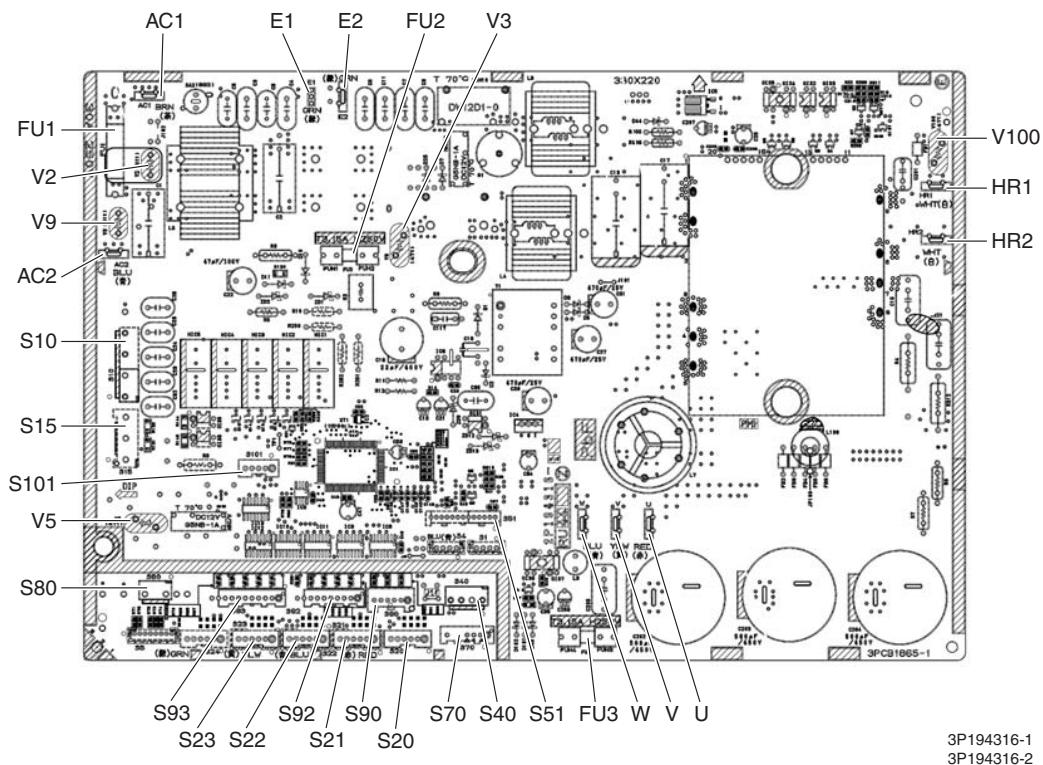
PCB (1): Main PCB (68/75 class)

PCB (1): Main PCB (80/90 class)

PCB (2): Service Monitor PCB (for 3 or 4-room model)

PCB (2): Service Monitor PCB (for 5-room model)
2. Indoor Unit
2.1 FTXG25/35/50JV1BW(A)
Connectors and Other Parts
[A1P]: Control PCB
1) S21 Connector for centralized control (HA)
2) S25 Connector for INTELLIGENT EYE sensor PCB
3) S32 Indoor heat exchanger thermistor
4) S41 Connector for swing motors
5) S42 Connector for reduction motor (front panel mechanism) and limit switch
6) S46 Connector for signal receiver / display PCB
7) S200 Connector for fan motor
8) H1, H2, H3, Connector for terminal board FG
9) JB Fan speed setting when compressor stops for thermostat OFF JC Power failure recovery function (auto_restart)
- Refer to page 418 for detail.
10) LED A LED for service monitor (green)
11) F1U Fuse (3.15 A, 250 V)
12) V1 Varistor
[A2P]: Signal Receiver / Display PCB
1) S51 Connector for control PCB
2) S52 Connector for room temperature thermistor
3) S1W Forced cooling operation [ON/OFF] button
4) H1P LED for operation (multi-color)
5) H2P LED for INTELLIGENT EYE (green)
6) JA Address setting jumper
- Refer to page 415 for detail.
[A3P]: INTELLIGENT EYE Sensor PCB
1) S36 Connector for control PCB
PCB Detail
[A1P]: Control PCB
![DAIKIN FNA-A - [A3P]: INTELLIGENT EYE Sensor PCB - 1](/content/2020/11/206419/images/166870c4cd66c25c86e17278a2a49a962401bae2934fd089cef7d40a60f7de6e.jpg)
![DAIKIN FNA-A - [A3P]: INTELLIGENT EYE Sensor PCB - 2](/content/2020/11/206419/images/c4c8bc9b0659b2c2fec1aa61a6a6177c2b42a9a071521af6e3f8c8dfdbe04d3d.jpg)
[A2P]: Signal Receiver / Display PCB
![DAIKIN FNA-A - [A3P]: INTELLIGENT EYE Sensor PCB - 3](/content/2020/11/206419/images/a50376251448b2f03a8c2d9545bcd5cc1f4e10892bc1f1136d5ae67391f85915.jpg)
[A3P]: INTELLIGENT EYE Sensor PCB
3P255914-1
2.2 FTXS20/25K2V1B, CTXS15/35K2V1B
Connectors and Other Parts
PCB(1): Control PCB
1) S6 Connector for swing motor (horizontal blade)
2) S25 Connector for INTELLIGENT EYE sensor PCB
3) S26 Connector for display PCB
4) S32 Connector for indoor heat exchanger thermistor
5) S200 Connector for fan motor
6) S403 Connector for adaptor PCB (option)
7) FG1, FG2 Connector for terminal board (frame ground)
8) H1, H2, H3 Connector for terminal board (indoor - outdoor transmission)
9) V1 Varistor
10)JA Address setting jumper
- Refer to page 415 for detail.
11)JB Fan speed setting when compressor stops for thermostat OFF JC Power failure recovery function (auto_restart)
- Refer to page 418 for detail.
12)LED A LED for service monitor (green)
13)FU1 (F1U) Fuse (3.15 A, 250 V)
PCB (2): Display PCB
1) S27 Connector for control PCB
2) SW1 (S1W) Forced cooling operation [ON/OFF] button
3) LED1 (H1P) LED for operation (green)
4) LED2 (H2P) LED for timer (yellow)
5) LED3 (H3P) LED for INTELLIGENT EYE (green)
6) RTH1 (R1T) Room temperature thermistor
PCB (3): INTELLIGENT EYE Sensor PCB
1) S36 Connector for control PCB
PCB Detail

PCB(1): Control PCB

PCB(2): Display PCB

(Solder side)

PCB(3): INTELLIGENT EYE Sensor PCB
2.3 FTXS25/35/42/50J2V1B
Connectors and Other Parts
PCB (1): Control PCB
1) S1 Connector for DC fan motor
2) S21 Connector for centralized control (HA)
3) S25 Connector for INTELLIGENT EYE sensor PCB
4) S32 Indoor heat exchanger thermistor
5) S41 Connector for swing motors
6) S46 Connector for display PCB
7) S47 Connector for signal receiver PCB
8) H1, H2, H3, Connector for terminal board FG
9) JA Address setting jumper
- Refer to page 415 for detail.
10) JB Fan speed setting when compressor stops for thermostat OFF
JC Power failure recovery function (auto_restart)
- Refer to page 418 for detail.
11) LED A LED for service monitor (green)
12) FU1 (F1U) Fuse (3.15 A, 250 V)
13) V1 Varistor
PCB (2): Signal Receiver PCB
1) S48 Connector for control PCB
PCB (3): Display PCB
1) S49 Connector for control PCB
2) SW1 Forced cooling operation [ON/OFF] button
3) LED1 (H1P) LED for operation (green)
4) LED2 (H2P) LED for timer (yellow)
5) LED3 (H3P) LED for INTELLIGENT EYE (green)
6) RTH1 (R1T) Room temperature thermistor
PCB (4): INTELLIGENT EYE Sensor PCB
1) S26 Connector for control PCB
PCB Detail
PCB (1): Control PCB

2P206687-1

PCB (2): Signal Receiver PCB

PCB (3): Display PCB

PCB (4): INTELLIGENT EYE Sensor PCB
2.4 FTXS60/71GV1B
Connectors and PCB (1): Control PCB
Other Parts
1) S1 Connector for DC fan motor
2) S21 Connector for centralized control (HA)
3) S25 Connector for INTELLIGENT EYE sensor PCB
4) S32 Connector for indoor heat exchanger thermistor
5) S41 Connector for swing motors
6) S46 Connector for display PCB
7) S47 Connector for signal receiver PCB
8) H1, H2, H3, Connector for terminal board FG
9) V1 Varistor
10)JA Address setting jumper
- Refer to page 415 for detail.
11) JB Fan speed setting when compressor stops for thermostat OFF
JC Power failure recovery function (auto_restart)
- Refer to page 418 for detail.
12)LED A LED for service monitor (green)
13)FU1 (F1U) Fuse (3.15 A, 250 V)
PCB (2): Signal Receiver PCB
1) S48 Connector for control PCB
PCB (3): Display PCB
1) S49 Connector for control PCB
2) SW1 Forced cooling operation [ON/OFF] button
3) LED1 (H1P) LED for operation (green)
4) LED2 (H2P) LED for timer (yellow)
5) LED3 (H3P) LED for INTELLIGENT EYE (green)
6) RTH1 (R1T) Room temperature thermistor
PCB (4): INTELLIGENT EYE Sensor PCB
1) S36 Connector for control PCB
PCB Detail
PCB (1): Control PCB
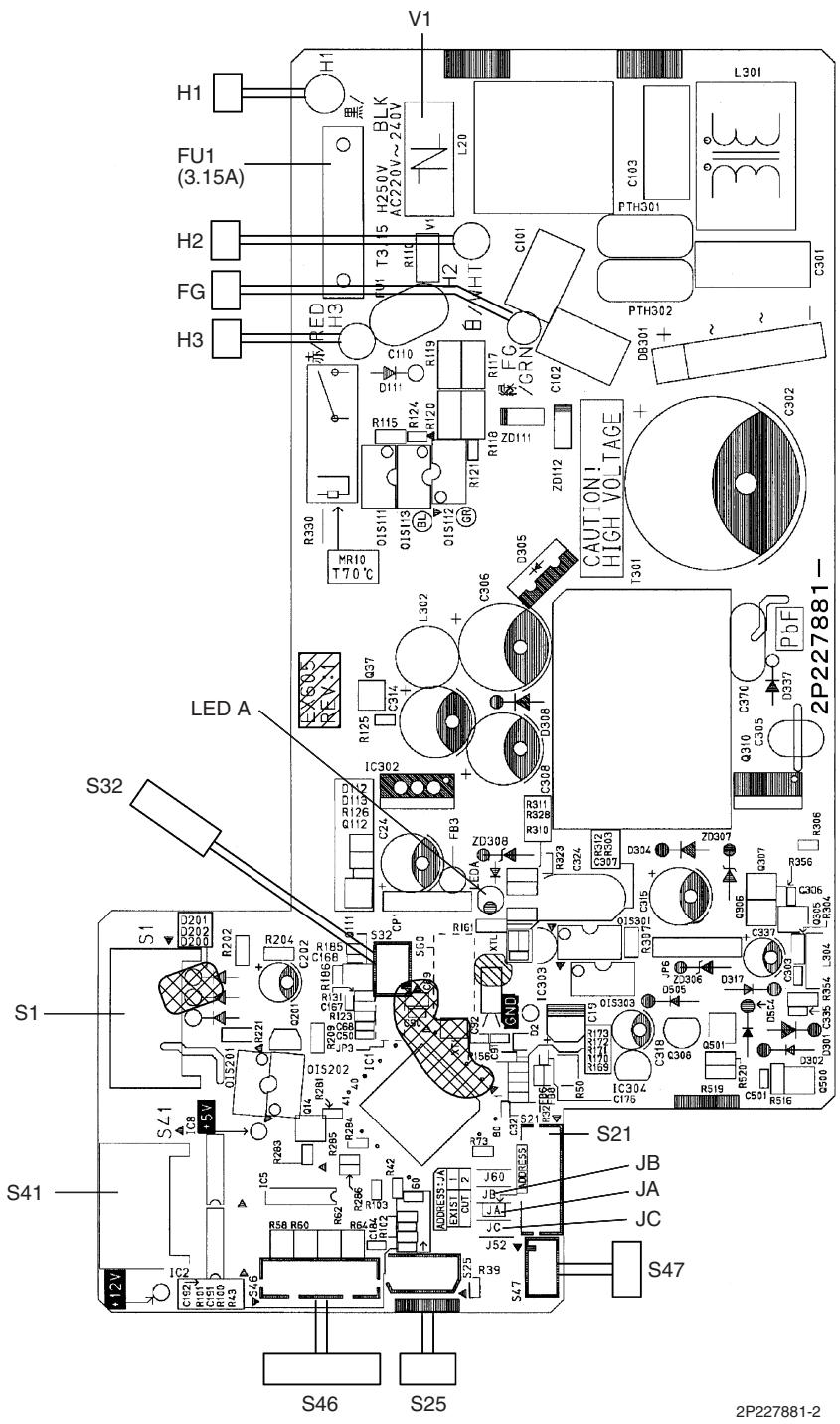

PCB (2): Signal Receiver PCB

PCB (3): Display PCB
PCB (4): INTELLIGENT EYE Sensor PCB

3P227885-1
2.5 FVXG25/35/50K2V1B
| Connectors and Other Parts | PCB (1): Main PCB |
| 1) S1 | Connector for fan motor |
| 2) S2 | Connector for terminal board |
| 3) S6 | Connector for swing motor |
| 4) S21 | Connector for centralized control (HA) |
| 5) S26 | Connector for service PCB |
| 6) S30 | Connector for indoor electronic expansion valve coil (motor operated valve coil) |
| 7) S32 | Connector for indoor heat exchanger thermistor |
| 8) S33 | Connector for room temperature thermistor |
| 9) S34 | Connector for radiant panel thermistors |
| 10)S46 | Connector for display PCB |
| 11)FG | Connector for earth |
| 12)V1 | Varistor |
| 13)JB | Fan speed setting when compressor stops for thermostat OFF |
| JC | Power failure recovery function
* Refer to page 418 for detail. |
| 14)F1U | Fuse (3.15A, 250V) |
| 15)LED A | LED for service monitor (green) |
| PCB (2): Display PCB |
| 1) S56 | Connector for main PCB |
| 2) S1W | Forced cooling operation [ON/OFF] button |
| 3) H1P | LED for operation (green) |
| 4) H2P | LED for timer (yellow) |
| 5) H3P | LED for RADIANT operation (red) |
| PCB (3): Service PCB |
| 1) S27 | Connector for main PCB |
| 2) S2W-1 | Address setting switch
* Refer to page 415 for detail.
* Keep the other switches as factory setting (OFF). |
PCB Detail
PCB (1): Main PCB

2P273247-1

PCB (2): Display PCB
PCB (3): Service PCB

3P273254-1
2.6 FVXS25/35/50FV1B
| Connectors and
Other Parts | PCB (1): Sensor PCB |
| 1) S49 | Connector for control PCB |
| 2) RTH2 (R1T) | Room temperature thermistor |
| PCB (2): Control PCB |
| 1) S1 | Connector for fan motor |
| 2) S21 | Connector for centralized control (HA) |
| 3) S26 | Connector for service PCB |
| 4) S32 | Indoor heat exchanger thermistor |
| 5) S41 | Connector for lower air outlet motor |
| 6) S42 | Connector for swing motor |
| 7) S46 | Connector for display PCB |
| 8) S48 | Connector for sensor PCB |
| 9) H1, H2, H3 | Connector for terminal board |
| 10)E1 | Terminal for earth |
| 11)V1, V2 | Varistor |
| 12)JA | Address setting jumper
* Refer to page 415 for detail. |
| 13)JB | Fan speed setting when compressor stops for thermostat OFF |
| JC | Power failure recovery function
* Refer to page 418 for detail. |
| 14) FU1 (F1U) | Fuse (3.15A, 250V) |
| 15) LED A | LED for service monitor (green) |
| PCB (3): Service PCB |
| 1) S27 | Connector for control PCB |
| 2) SW2-4 | Switch for upward airflow limit setting
* Refer to page 418 for detail.
* Keep the other switches as factory setting. |
| 3) SW4 (S4W) | Switch for air outlet selection
* Refer to page 185, 195 for detail. |
| PCB (4): Display PCB |
| 1) S47 | Connector for control PCB |
| 2) SW1 (S1W) | Forced cooling operation [ON/OFF] button |
| 3) LED1 (H1P) | LED for operation (green) |
| 4) LED2 (H2P) | LED for timer (yellow) |
PCB Detail
PCB (1): Sensor PCB

3P191450-1
PCB (2): Control PCB

2P191446-1
PCB (3): Service PCB

3P191448-1
PCB (4): Display PCB

LED3 does not function.
2.7 FLXS25/35/50/60BAVMB
Connectors and PCB (1): Control PCB
Other Parts
1) S6 Connector for swing motor (horizontal swing)
2) S7 Connector for AC fan motor
3) S21 Connector for centralized control (HA)
4) S24 Connector for display PCB
5) S26 Connector for signal receiver PCB
6) S32 Connector for indoor heat exchanger thermistor
7) S37 Connector for power supply PCB
8) JA Address setting jumper
- Refer to page 415 for detail.
9) JB Fan speed setting when compressor stops for thermostat OFF
JC Power failure recovery function
- Refer to page 418 for detail.
10) SW2 Select switch for installation (ceiling or floor)
- Refer to page 418 for detail.
11) LED A LED for service monitor (green)
PCB (2): Power Supply PCB
1) S36 Connector for control PCB
2) H1, H2, H3 Connector for terminal board
3) H4, H5, H6 Connector for AC fan motor
4) V1 Varistor
5) FU1 Fuse (3.15A, 250V)
PCB (3): Display PCB
1) S25 Connector for control PCB
2) LED1 (H1P) LED for operation (green)
3) LED2 (H2P) LED for timer (yellow)
4) LED3 (H3P) LED for HOME LEAVE operation (red)
PCB (4): Signal Receiver PCB
1) S27 Connector for control PCB
2) S31 (RTH) Room temperature thermistor
3) SW1 (S1W) Forced cooling operation [ON/OFF] button
PCB Detail

PCB (1): Control PCB

PCB (2): Power Supply PCB

PCB (3): Display PCB

PCB (4): Signal Receiver PCB
2.8 FDXS25/35E7VMB, FDXS50/60C7VMB
Connectors and Other Parts
PCB (1): Control PCB
1) S1 Connector for AC fan motor
2) S7 Connector for AC fan motor (Hall IC)
3) S21 Connector for centralized control (HA)
4) S26 Connector for display PCB
5) S32 Connector for indoor heat exchanger thermistor
6) H1, H2, H3 Connector for terminal board
7) GND Connector for terminal board (earth)
8) JA Address setting jumper
- Refer to page 415 for detail.
9) JB Fan speed setting when compressor stops for thermostat OFF
JC Power failure recovery function (auto_restart)
Refer to page 418 for detail.
10) LED A LED for service monitor (green)
11) FU1 (F1U) Fuse (3.15A, 250V)
12) V1 (V1TR) Varistor
PCB (2): Display PCB
1) S1 Connector for control PCB
2) SW1 (S1W) Forced cooling operation [ON/OFF] button
3) LED1 (H1P) LED for HOME LEAVE operation (red)
4) LED2 (H2P) LED for timer (yellow)
5) LED3 (H3P) LED for operation (green)
6) RTH1 (R1T) Room temperature thermistor
PCB Detail

PCB (1): Control PCB

PCB (2): Display PCB
2P084375-1
2.9 FCQG35/50/60FVEB
Connectors and [A1P]
Other Parts
1) X15A Connector for float switch
2) X16A Connector for room temperature thermistor
3) X17A, X18A Connector for indoor heat exchanger thermistor
4) X20A Connector for fan motor
5) X24A Connector for signal receiver PCB
(when the wireless remote controller is used)
6) X27A Connector for terminal board (for inter-unit wiring)
7) X30A Connector for terminal board (for wired remote controller)
8) X33A Connector for wiring adaptor PCB (option)
9) X35A Connector for group control adaptor (option)
10) X36A Connector for self-cleaning decoration panel (option)
11) X65A, X70A Connector for [A2P]
12) HAP LED for service monitor (green)
13) SS1 Selector switch for emergency
[A2P]
1) X1A, X7A Connector for [A1P]
2) X2A Connector for sensor kit (option)
3) X4A Connector for humidity sensor PCB [A3P]
4) X8A Connector for self-cleaning decoration panel (option)
5) X9A Connector for swing motors
6) X10A Connector for drain pump motor
7) HAP LED for service monitor (green)
[A3P]: Humidity Sensor PCB
1) CN1 Connector for [A2P]
PCB Detail
[A1P]
![DAIKIN FNA-A - [A3P]: Humidity Sensor PCB - 1](/content/2020/11/206419/images/d0d935bc07c2d2b59b68202bbd73fe798648acc377a28c1391d598667614614e.jpg)
2P263068-4
[A2P]
![DAIKIN FNA-A - [A3P]: Humidity Sensor PCB - 2](/content/2020/11/206419/images/75c6e89f0b029552652aecee2fad115d0d0d092b2a5609d4220382f754eb0ef2.jpg)
2P263045-1
![DAIKIN FNA-A - [A3P]: Humidity Sensor PCB - 3](/content/2020/11/206419/images/7f44e3c001c5b6ddcc6a1169875d499219f4bbfd3ba1ca7471cdd746b500938d.jpg)
[A3P]: Humidity Sensor PCB
2.10 FFQ25/35/50/60B9V1B
Connectors and [A1P]: Control PCB
Other Parts
1) X5A Connector for terminal board (for wired remote controller)
2) X10A, X11A Connector for transformer
3) X15A Connector for float switch
4) X17A, X18A Connector for indoor heat exchanger thermistor
5) X19A Connector for room temperature thermistor
6) X20A Connector for fan motor
7) X24A Connector for signal receiver PCB
(when the wireless remote controller is used)
8) X25A Connector for drain pump motor
9) X27A Connector for terminal board (for inter-unit wiring)
10) X33A Connector for wiring adaptor PCB (option)
11) X35A Connector for group control adaptor (option)
12) X36A Connector for swing motor
13) X40A Connector for ON/OFF input from outside (option)
14) X60A, X61A Connector for interface adaptor (option)
15) HAP LED for service monitor (green)
16) SS1 Selector switch for emergency
PCB Detail

[A1P]: Control PCB
2.11 FHQ35/50/60BWV1B
Connectors and [A1P]: Control PCB
Other Parts
1) X5A Connector for terminal board (for wired remote controller)
2) X10A, X11A Connector for transformer
3) X14A Connector for limit switch (for swing flap)
4) X15A Connector for float switch (option)
5) X17A, X18A Connector for indoor heat exchanger thermistor
6) X19A Connector for room temperature thermistor
7) X20A, X26A Connector for fan motor
8) X24A Connector for signal receiver PCB (when the wireless remote controller is used)
9) X25A Connector for drain pump motor (option)
10) X27A Connector for terminal board (for inter-unit wiring)
11) X29A Connector for swing motor
12) X33A Connector for wring adaptor PCB (option)
13) X35A Connector for group control adaptor (option)
14) X40A Connector for ON/OFF input from outside (option)
15) X60A, X61A Connector for interface adaptor (option)
16) HAP LED for service monitor (green)
17) SS1 Selector switch for emergency
PCB Detail

[A1P]: Control PCB
2.12 FDBQ25B8V1
Connectors and Other Parts
[A1P]: Control PCB
1) X5A Connector for terminal board (for wired remote controller)
2) X10A, X11A Connector for transformer
3) X17A Connector for indoor heat exchanger thermistor
4) X18A Connector for liquid pipe thermistor
5) X19A Connector for room temperature thermistor
6) X21A Connector for fan motor
7) X27A Connector for terminal board (for inter-unit wiring)
8) X33A Connector for wiring adaptor PCB (option)
9) X35A Connector for group control adaptor (option)
10) X40A Connector for ON/OFF input from outside (option)
11) X60A, X61A Connector for interface adaptor (option)
12) HAP LED for service monitor (green)
13) SS1 Selector switch for emergency
PCB Detail

[A1P]: Control PCB
2.13 FBQ35/50/60C8VEB
Connectors and Other Parts
[A1P]: Control PCB
| 1) | X15A | Connector for float switch |
| 2) | X16A | Connector for room temperature thermistor |
| 3) | X17A | Connector for indoor heat exchanger thermistor |
| 4) | X18A | Connector for liquid pipe thermistor |
| 5) | X25A | Connector for drain pump motor |
| 6) | X27A | Connector for terminal board (for inter-unit wiring) |
| 7) | X28A | Connector for power supply wiring (option) |
| 8) | X30A | Connector for terminal board (for wired remote controller) |
| 9) | X33A | Connector for wiring adaptor PCB (option) |
| 10) | X35A | Connector for group control adaptor (option) |
| 11) | X70A | Connector for fan PCB |
| 12) | X85A | Connector for multi zoning (option) |
| 13) | HAP | LED for service monitor (green) |
| 14) | SS1 | Selector switch for emergency |
[A2P]: Fan PCB (for FBQ35/50C8VEB)
| 1) | X3A | Connector for control PCB |
| 2) | X6A | Connector for reactor |
| 3) | X8A | Connector for fan motor |
| 4) | X10A | Connector for terminal board (power supply) |
| 5) | F2U | Fuse (5 A, 250 V) |
| 6) | F4U | Fuse (6.3 A, 250 V) |
| 7) | HAP | LED for service monitor (green) |
[A2P]: Fan PCB (for FBQ60C8VEB)
| 1) | X1A, X2A | Connector for fan motor |
| 2) | X3A | Connector for control PCB |
| 3) | X6A | Connector for reactor |
| 4) | X9A | Connector for capacitor PCB |
| 5) | X10A | Connector for terminal board (power supply) |
| 6) | F3U | Fuse (6.3 A, 250 V) |
| 7) | HAP | LED for service monitor (green) |
[A3P]: Capacitor PCB (FBQ60C8VEB only)
![DAIKIN FNA-A - [A3P]: Capacitor PCB (FBQ60C8VEB only) - 1](/content/2020/11/206419/images/f3c3cf7ce6d8dc38ea58b8ad7d9a54c37b92f22b9a36c87aa6a60def3b73e8c0.jpg)
Connector for X9A on fan PCB
3P217472-1
PCB Detail

[A1P]: Control PCB

[A2P]: Fan PCB (for FBQ35/50C8VEB)

[A2P]: Fan PCB (for FBQ60C8VEB)
3. Wired Remote Controller
3.1 BRC1D528
Connectors and Other Parts
1) P1, P2 Terminal for indoor unit
2) R1T Room temperature thermistor
3) SS1 MAIN / SUB setting switch
- Refer to page 422 for detail.
PCB Detail

2P113638-2
3.2 BRC1E52A7, BRC1E52B7
Connectors and
1) P1, P2
Terminal for indoor unit
Other Parts
2) R1T
Room temperature thermistor
PCB Detail

Part 4
Function and Control
1. Indoor Unit Control (RA Models) 76
1.1 Temperature Control 76
1.2 Frequency Principle 76
1.3 Operation Starting Control 78
1.4 Airflow Direction Control 79
1.5 Fan Speed Control for Indoor Unit 82
1.6 RADIANT Operation 83
1.7 Program Dry Operation 85
1.8 Automatic Operation 86
1.9 Thermostat Control 87
1.10 NIGHT SET Mode 89
1.11 ECONO Operation 90
1.12 HOME LEAVE Operation 91
1.13 INTELLIGENT EYE Operation 92
1.14 2-Area INTELLIGENT EYE Operation .93
1.15 Inverter POWERFUL Operation 95
1.16 Multi-Colored Indicator Lamp / TIMER Lamp 95
1.17 Other Functions 97
2. Indoor Unit Control (SA Models) 99
2.1 Drain Pump Control 99
2.2 Thermostat Sensor in Remote Controller 101
2.3 Freeze Prevention Control 103
2.4 Hot Start Control (In Heating Operation Only) 104
3. Function of Thermistor 105
4. Control Specification 107
4.1 Mode Hierarchy 107
4.2 Frequency Control 108
4.3 Controls at Mode Changing / Start-up 111
4.4 Discharge Pipe Temperature Control 112
4.5 Input Current Control 113
4.6 Freeze-up Protection Control 113
4.7 Heating Peak-cut Control 114
4.8 Outdoor Fan Control 115
4.9 Liquid Compression Protection Function 115
4.10 Defrost Control 116
4.11 Low Hz High Pressure Limit 117
4.12 Outdoor Electronic Expansion Valve Control 117
4.13 Malfunctions 122
1. Indoor Unit Control (RA Models)
1.1 Temperature Control
Definitions of Temperatures
The definitions of temperatures are classified as following.
Room temperature: temperature of lower part of the room
- Set temperature: temperature set by remote controller
Room thermistor temperature: temperature detected by room temperature thermistor
Target temperature: temperature determined by microcomputer

The illustration is for wall mounted type as representative.
Temperature Control
The temperature of the room is detected by the room temperature thermistor. However, there is a difference between the "temperature detected by room temperature thermistor" and the "temperature of lower part of the room", depending on the type of the indoor unit or installation condition. Practically, the temperature control is done by the "target temperature appropriately adjusted for the indoor unit" and the "temperature detected by room temperature thermistor".
1.2 Frequency Principle
Main Control Parameters
The frequency of the compressor is controlled by the following 2 parameters:
The load condition of the operating indoor unit
The difference between the room thermistor temperature and the target temperature
Additional Control Parameter:
The target frequency is adapted by additional parameters in the following cases:
Frequency restrictions
Initial settings
Forced cooling operation
Inverter Principle
To regulate the capacity, a frequency control is needed. The inverter makes it possible to alter the rotation speed of the compressor. The following table explains the conversion principle:
| Phase | Description |
| 1 | The supplied AC power source is converted into the DC power source for the present. |
| 2 | The DC power source is reconverted into the three phase AC power source with variable frequency.
■ When the frequency increases, the rotation speed of the compressor increases resulting in an increased refrigerant circulation. This leads to a higher amount of the heat exchange per unit.
■ When the frequency decreases, the rotation speed of the compressor decreases resulting in a decreased refrigerant circulation. This leads to a lower amount of the heat exchange per unit. |
Drawing of Inverter
The following drawing shows a schematic view of the inverter principle:
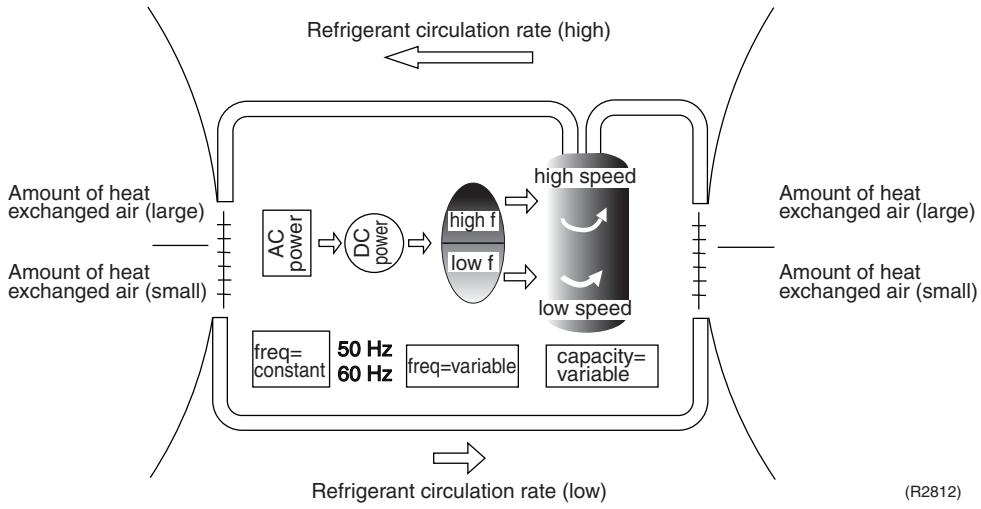
Inverter Features
The inverter provides the following features:
The regulating capacity can be changed according to the changes in the outdoor temperature and cooling / heating load.
- Quick heating and quick cooling
- The compressor rotational speed is increased when starting the heating (or cooling). This enables to reach the set temperature quickly.
Even during extreme cold weather, high capacity is achieved. It is maintained even when the outdoor temperature is 2^ .
Comfortable air conditioning
A fine adjustment is integrated to keep the room temperature constant.
Energy saving heating and cooling
Once the set temperature is reached, the energy saving operation enables to maintain the room temperature at low power.
Frequency Limits
The following functions regulate the minimum and maximum frequency:
| Frequency | Functions |
| Low | ■ Four way valve operation compensation. Refer to page 111. |
| High | ■ Compressor protection function. Refer to page 112.■ Discharge pipe temperature control. Refer to page 112.■ Input current control. Refer to page 113.■ Freeze-up protection control. Refer to page 113.■ Heating peak-cut control. Refer to page 114.■ Defrost control. Refer to page 116. |
Forced Operation
Refer to page 405 for detail.
1.3 Operation Starting Control
Outline
Wall Mounted Type: FTXG Series
The system carries out the following control at the beginning to conduct every functional parts properly.
- Opening the front panel fully
- Output of the D signal after the front panel starts moving
- Opening the flap fully after the front panel opens fully
- Making the fan rotate when the flap passes over the fan-banned area
Control Flow

Timing Chart

(R11910)
1.4 Airflow Direction Control
Power-Airflow Dual Flaps
The large flap sends a large volume of air downward to the floor. The flap provides an optimum control in cooling, dry, and heating operation.
During cooling or dry operation, the flap retracts into the indoor unit. Then, cool air can be blown far and distributed all over the room.
During heating operation, the large flap directs airflow downward to spread the warm air to the entire room.
Wide-Angle Louvers
The louvers, made of elastic synthetic resin, provide a wide range of airflow that guarantees comfortable air distribution.
Auto-Swing
The following table explains the auto-swing process for cooling, dry, heating, and fan: Wall Mounted Type
| Series | Vertical Swing (up and down) | Horizontal Swing (right and left) |
| Cooling / Dry | Heating | Fan |
| FTXG | 10° 15° 60° 65° (R11662) | 20° 25° 70° (R11664) | 5° 10° 80° (R11663) | - |
| FTXS-K | 5° 45° (R11256) | 15° 45° (R11257) | 5° 45° (R11256) | - |
| CTXS-K |
| FTXS-J | 15° 30° 50° 55° (R12182) | 30° 30° 65° (R11402) | 8° 30° 65° (R14208) | (R11404) |
| FTXS-G | 10° 40° 10° 40° (R2814) | 5° 5° 35° 35° (R2815) | 15° 55° 55° (R2813) | 5° 5° 55° (R2816) | (R2817) |
Floor Standing Type: FVXG Series
The swinging range of the flap is the same in any operation mode.

(R14634)
Floor Standing Type: FVXS Series
| Vertical Swing (up and down) |
| Cooling / Dry | Heating |
| Upward airflow limit OFF | (25°)
(R6831) | (40°)
(R6829) |
| Upward airflow limit ON | 20°
(R6832) | 20°
(R6830) |
Floor / Ceiling Suspended Dual Type
| Vertical Swing (up and down) |
| Cooling / Dry / Fan | Heating |
| Ceiling | (R2964) | (R2963) |
| Floor | (R2967) | (R2966) |
3-D Airflow
Wall Mounted Type: FTXS-J/G Series
Alternative repetition of vertical and horizontal swing motions enables uniform air-conditioning of the entire room. This function is effective for starting the air conditioner.
When the horizontal swing and vertical swing are both set to automatic operation, the airflow becomes 3-D airflow. The horizontal and vertical swing motion is altered and the airflow direction changes in the order shown in the following diagram.
(1): The vertical blades (louvers) move from the right to the left.
(2): The horizontal blades (flaps) move downward.
(3): The vertical blades (louvers) move from the left to the right.
(4): The horizontal blades (flaps) move upward.

(R13554)
COMFORT AIRFLOW Operation
Wall Mounted Type
The vertical swing flap is controlled not to blow the air directly at the people in the room.
| Cooling / Dry | Heating |
| A
(R11665) | B
(R12181) |
| A | B |
| FTXG | 5° | 75° |
| FTXS-K, CTXS-K | 0° | 50° |
| FTXS-J | 8° | 80° |
| FTXS-G | 5° | 55° |
1.5 Fan Speed Control for Indoor Unit
Outline
Phase control and fan speed control contains 9 steps: LLL, LL, SL, L, ML, M, MH, H, and HH. The airflow rate can be automatically controlled depending on the difference between the room thermistor temperature and the target temperature. This is done through phase control and Hall IC control.

For more information about Hall IC, refer to the troubleshooting for fan motor on page 274, 277.
Automatic Fan Speed Control
In automatic fan speed operation, the step "SL" is not available.
| Wall Mounted Type
Floor Standing Type | Floor / Ceiling Suspended Dual Type
Duct Connected Type |
| Step | Cooling | Heating | Cooling | Heating |
| LLL | (R11681) | (R6834) | (R6833) | (R6834) |
| LL |
| L |
| ML |
| M |
| MH |
| H |
| HH (POWERFUL) |
= The airflow rate is automatically controlled within this range when the [FAN] setting button is set to automatic.
The following drawing explains the principle of fan speed control for cooling.
Wall Mounted Type, Floor Standing Type
Room thermistor temperature - target temperature

*The upper limit is M tap in 30 minutes from the operation start.
(R12317)
Floor / Ceiling Suspended Dual Type, Duct Connected Type

Room thermistor temperature - target temperature
(R12390)
In heating operation, the fan speed is regulated according to the indoor heat exchanger temperature and the difference between the room thermistor temperature and the target temperature.

Note:
- During POWERFUL operation, the fan rotates at H tap + 40 ~ 90 rpm.
- The fan stops during defrost operation.
COMFORT
Wall Mounted Type
The fan speed is controlled automatically.
The latest command has the priority between POWERFUL and COMFORT AIRFLOW.
1.6 RADIANT Operation
| Outline | Floor Standing Type: FVXG Series
The RADIANT operation has 2 operation modes.
• RADIANT 1: RADIANT operation with heating
• RADIANT 2: RADIANT operation only | |
| 1.6.1 Indoor Electronic Expansion Valve (Motor Operated Valve) Control | |
| Initializing with Power ON | The indoor electronic expansion valve is initialized when turning on the power. | |
| Opening Limit Control | Opening limit control limits the opening of the indoor electronic expansion valve in order to keep a specified range during RADIANT operation. | |
| Starting Operation Control | Starting operation control opens the indoor electronic expansion valve to a certain degree when starting RADIANT operation. The indoor electronic expansion valve is kept open for a certain period. | |
| Target Panel Temperature Control | When the starting operation control finishes, the target panel temperature control starts and adjusts the opening of the indoor electronic expansion valve to achieve the target panel temperature. The panel temperature is categorized into stop, dropping, keep, up, and return zones.
(The target panel temperature is 55°C at maximum but it may be lower depending on the condition.) | |
| Radiator panel temperature
70°C
Dropping zone
55°C
Keep zone
53°C
Up zone
45°C
Up zone / return zone from stop
(R14636) | |
| Stop zone | Operation stops, the radiant panel temperature control is carried out. |
| Dropping zone | The opening of indoor electronic expansion valve decreases. |
| Keep zone | The opening of indoor electronic expansion valve is kept. |
| Up zone | The opening of indoor electronic expansion valve increases. |
| Return zone | Starting operation control is carried out. |
| Operation Stop Control | ■ In case operation stops during RADIANT operation (including thermostat off)
In case any of the following events occur while the indoor electronic expansion valve is open, the operation stop control makes the indoor electronic expansion valve close completely.
• Operation ON → OFF
• RADIANT 1 or RADIANT 2 is canceled.
• Thermostat off
• Defrost control | |
1.6.2 Indoor Unit Fan Control
The movement of the indoor unit fan is different whether in RADIANT 1 or RADIANT 2.

(R14637)
1.6.3 RADIANT Operation and Optional Function
Some optional function cannot be used with RADIANT 1 or RADIANT 2 at the same time.
| Function | RADIANT 1 | RADIANT 2 |
| POWERFUL operation | available | not available |
| ECONO operation | not available | not available |
| OUTDOOR UNIT
QUIET operation | not available | not available |
1.7 Program Dry Operation
Outline
Program dry operation removes humidity while preventing the room temperature from lowering. Since the microcomputer controls both the temperature and airflow rate, the temperature adjustment and [FAN] setting buttons are inoperable.
Detail
The microcomputer automatically sets the temperature and airflow rate. The difference between the room thermistor temperature at start-up and the target temperature is divided into two zones. Then, the unit operates an appropriate capacity for each zone to maintain the temperature and humidity at a comfortable level.
| Room thermistor temperature at start-up | Target temperature X | Thermostat OFF point Y | Thermostat ON point Z |
| 24°C or more | Room thermistor temperature at start-up | X - 2.5°C | X - 0.5°C or Y + 0.5°C (zone B) continues for 10 min. |
| 23.5°C | X - 2.0°C | X - 0.5°C or Y + 0.5°C (zone B) continues for 10 min. |
| 18°C |
| 17.5°C | 18°C | X - 2.0°C | X - 0.5°C = 17.5°C or Y + 0.5°C (zone B) continues for 10 min. |

Zone A = Thermostat OFF
(R11581)
1.8 Automatic Operation
Outline
Automatic Cooling / Heating Function
When the automatic operation is selected with the remote controller, the microcomputer automatically determines the operation mode as cooling or heating according to the room temperature and the set temperature at start-up.
The unit automatically switches the operation mode to maintain the room temperature at the set temperature.
Detail
Ts: set temperature (set by remote controller)
Tt: target temperature (determined by microcomputer)
Tr: room thermistor temperature (detected by room temperature thermistor)
C: correction value
- The set temperature (Ts) determines the target temperature (Tt). (Ts = 18 30^)
- The target temperature (Tt) is calculated as;
Tt = Ts + C
where C is the correction value.
C = 0^
- Thermostat ON/OFF point and operation mode switching point are as follows.
Tr means the room thermistor temperature.
(1) Heating Cooling switching point:
Tr ≥ Tt + 3.0^ (FTXG, FTXS-G, FVXG series)
Tr≥ Tt + 2.5^ (other models)
(2) Cooling Heating switching point:
Tr < Tt - 2.5^
(3) Thermostat ON/OFF point is the same as the ON/OFF point of cooling or heating operation.
- During initial operation
Tr≥ Ts :Cooling operation
Tr < Ts : Heating operation
FTXG, FTXS-G, FVXG series

Ex: When the target temperature is 25^
Cooling 23^ : Thermostat OFF 22^ : Switch to heating
Heating 27^ : Thermostat OFF 28^ : Switch to cooling
Other Models

Ex: When the target temperature is 25^
Cooling 23^ : Thermostat OFF 22^ : Switch to heating
Heating 26.5^ : Thermostat OFF 27.5^ : Switch to cooling
1.9 Thermostat Control
Thermostat control is based on the difference between the room thermistor temperature and the target temperature.
Thermostat OFF Condition
The temperature difference is in the zone A.
Thermostat ON Condition
The temperature difference returns to the zone C after being in the zone A.
The system resumes from defrost control in any zones except A.
The operation turns on in any zones except A.
The monitoring time has passed while the temperature difference is in the zone B. (Cooling / Dry : 10 minutes, Heating / Radiant : 10 seconds)
Wall Mounted Type, Floor Standing Type

Room thermistor temperature - target temperature
Cooling: -0.5^ Dry: -0.5^
Cooling: -2.0^
Dry: -2.5 -2.0^ C
(R12319)
Floor / Ceiling Suspended Dual Type, Duct Connected Type

Room thermistor temperature - target temperature
Cooling: -1.0^
Dry: -1.0^
Cooling: -2.0^
Dry: -2.5 -2.0^ C
(R12391)
Wall Mounted Type: FTXG, FTXS-G series
Floor Standing Type: FVXG series

Room thermistor temperature - target temperature
(R11894)
Wall Mounted Type: FTXS-K, CTXS-K, FTXS-J series
Floor Standing Type: FVXS series

Room thermistor temperature - target temperature
(R12320)
Floor / Ceiling Suspended Dual Type, Duct Connected Type

(R12392)

Refer to "Temperature Control" on page 76 for detail.
1.10 NIGHT SET Mode
Outline
When the OFF TIMER is set, the NIGHT SET Mode is automatically activated. The NIGHT SET Mode keeps the airflow rate setting.
Detail
The NIGHT SET Mode continues operation at the target temperature for the first one hour, then automatically raises the target temperature slightly in the case of cooling, or lowers it slightly in the case of heating. This prevents excessive cooling in summer and excessive heating in winter to ensure comfortable sleeping conditions, and also conserves electricity.
Ex: Wall Mounted Type, Floor Standing Type

(R10870)

1.11 ECONO Operation
Wall Mounted Type, Floor Standing Type
The "ECONO operation" reduces the maximum operating current and the power consumption. This operation is particularly convenient for energy-saving-oriented users. It is also a major bonus for those whose breaker capacities do not allow the use of multiple electrical devices and air conditioners.
It is easily activated from the wireless remote controller by pushing the [ECONO] button.
- When this function is activated, the maximum capacity also decreases.
ECONO operation can only be set when the unit is running. Pressing the [ON/OFF] button on the remote controller cancels the function.
ECONO operation is available when the unit is in AUTO, COOL, DRY, or HEAT operation and not available in RADIANT or FAN operation.
ECONO operation and POWERFUL operation cannot be used at the same time. The latest command has the priority.

1.12 HOME LEAVE Operation
Outline
Floor / Ceiling Suspended Dual Type, Duct Connected Type
HOME LEAVE operation is a function that allows you to record your favorite set temperature and airflow rate. You can start your favorite operation mode simply by pressing the [HOME LEAVE] button on the remote controller.
Detail
1. Start of Function
The function starts when the [HOME LEAVE] button is pressed in cooling mode, heating mode (including POWERFUL operation), or while the operation is stopped. If this button is pressed in POWERFUL operation, the POWERFUL operation is canceled and this function becomes effective.
The [HOME LEAVE] button is ineffective in dry mode and fan mode.
2. Details of Function
A mark representing HOME LEAVE is indicated on the display of the remote controller. The indoor unit is operated according to the set temperature and airflow rate for HOME LEAVE which were pre-set in the memory of the remote controller.
The LED (red) of indoor unit representing HOME LEAVE lights up. (It goes out when the operation is stopped.)
3. End of Function
The function ends when the [HOME LEAVE] button is pressed again during HOME LEAVE operation or when the [POWERFUL] button is pressed.


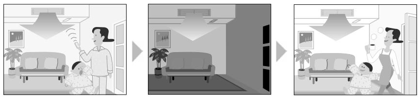

Others
The set temperature and airflow rate are memorized in the remote controller. When the remote controller is reset due to replacement of battery, it is necessary to set the temperature and airflow rate again for HOME LEAVE operation.
1.13 INTELLIGENT EYE Operation
Outline
Wall Mounted Type: FTXG, FTXS-K, CTXS-K, FTXS-G Series
This function detects the existence of humans in the room with a human motion sensor (INTELLIGENT EYE) and reduces the capacity when there is nobody in the room in order to save electricity.
Detail

1. Detection method by INTELLIGENT EYE
The sensor detects human motion by receiving infrared rays and displays the pulse wave output.
A microcomputer in an indoor unit carries out a sampling every 20 msec. and if it detects 10 cycles of the wave in 1 second in total (corresponding to 20 msec. × 10 = 200 msec.), it judges humans are in the room as the motion signal is ON.

2. The motions (for example: in cooling)
- When the microcomputer does not have a signal from the sensor in 20 minutes, it judges that nobody is in the room and operates the unit at a temperature shifted from the target temperature. (Cooling / Dry: 1 2^ higher, Heating: 2^ lower, Auto: according to the operation mode at that time.)
In FAN operation, the fan speed is reduced by 60 rpm.
Others
- For dry operation, you cannot set the temperature with a remote controller, but the target temperature is shifted internally.
1.14 2-Area INTELLIGENT EYE Operation
Outline
Wall Mounted Type: FTXS-J Series
The following functions can be performed by a motion sensor (INTELLIGENT EYE).
- Reduction of the capacity when there is nobody in the room in order to save electricity (energy saving operation)
- Dividing the room into plural areas and detecting existence of humans in each area. Moving the airflow direction to the area with no human automatically to avoid direct airflow on humans.
Detail

1. Detection method of INTELLIGENT EYE
This sensor detects human motion by receiving infrared rays and displays the pulse wave output.
- The microcomputer in the indoor unit carries out a sampling every 20 msec. and if it detects 10 cycles of the wave in one second in total (corresponding to 20 msec. × 10 = 200 msec.), and when the ON signal continues 3 sec., it judges human is in the room as the motion signal is ON
2-area INTELLIGENT EYE sensor is divided into 2 areas and detects humans in each area.
Image of 2-area INTELLIGENT EYE

- A microcomputer judges human existence by the sensor signal from each area A and B.
(R12276)
2. Motions (for example: in cooling)

- When the microcomputer does not have a signal from the sensor in 20 minutes, it judges that nobody is in the room and operates the unit in temperature shifted from the target temperature. (Cooling / Dry : 2^ higher, Heating : 2^ lower, Auto : according to the operation mode at that time.)
In case of FAN operation, the fan speed reduces by 60 rpm.
3. Airflow direction in 2-area INTELLIGENT EYE operation
Detection method: The opposite area of detected area is set as the target direction.

- Detection signal ON in both area A and B: Shift the airflow direction to area B (left side)
- Detection signal ON in area A: Shift the airflow direction to area B (left side)
- Detection signal ON in area B: Shift the airflow direction to area A (right side)
-
Detection signal OFF in both area A and B: No change
-
When the detection signal is OFF for 20 minutes in both area A and B, the unit starts energy saving operation.
Others
- For dry operation, you cannot set the temperature with remote controller, but internally the target temperature is shifted.
1.15 Inverter POWERFUL Operation
Outline
In order to exploit the cooling and heating capacity to full extent, operate the air conditioner by increasing the indoor fan rotating speed and the compressor frequency.
Detail
When the [POWERFUL] button is pressed, the fan speed and target temperature are converted to the following states for 20 minutes.
| Operation mode | Fan speed | Target temperature |
| COOL | H tap + A rpm | 18°C |
| DRY | Dry rotating speed + A rpm | Lowered by 2 ~ 2.5°C |
| HEAT / RADIANT 1 | H tap + A rpm | 30 ~ 32°C |
| FAN | H tap + A rpm | — |
| AUTO | Same as cooling / heating in POWERFUL operation | The target temperature is kept unchanged. |
A = 40 90 rpm (depending on the model)
Ex: POWERFUL operation in cooling

(R13571)

For Floor Standing Type: FVXG Series
POWERFUL operation is only available in RADIANT 1 (RADIANT operation with heating), it is not available in RADIANT 2 (RADIANT operation only).
1.16 Multi-Colored Indicator Lamp / TIMER Lamp
Features
Wall Mounted Type: FTXG Series
Current operation mode is displayed in color of the lamp of the indoor unit. Operating status can be monitored even in automatic operation in accordance with the actual operation mode.

The lamp color changes according to the operation.
- AUTO............ Red / Blue
- DRY .........Green
*COOL. Blue
- HEAT . Red
- FAN. White
- TIMER............Orange
Brightness Setting
The brightness of the multi-colored indicator lamp can be adjusted L (low), H (high), or OFF.
- Press the center of the [Temp] button and the [Mode] button at the same time.

5C is displayed on the LCD.

- Select (light) with the [Temp] or button.

- Press the [Mode] button to enter the brightness setting mode.
- Press the [Temp] or button to adjust the brightness of the multi-colored indicator lamp.

(R11913)
- Press the [Mode] button for 5 seconds to exit from the brightness setting mode.
(When the remote controller is left untouched for 60 seconds, it returns to the normal mode also.)
1.17 Other Functions
1.17.1 Hot-Start Function
In order to prevent the cold air blast that normally comes when heating operation is started, the temperature of the indoor heat exchanger is detected, and the airflow is either stopped or made very weak thereby carrying out comfortable heating of the room.
- The cold air blast is also prevented using similar control when the defrosting operation is started or when the thermostat is turned ON.
1.17.2 Signal Receiving Sign
When the indoor unit receives a signal from the remote controller, the unit emits a signal receiving sound.
An [ON/OFF] button is provided on the display of the unit.
Press the [ON/OFF] button once to start operation. Press once again to stop it.
The [ON/OFF] button is useful when the remote controller is missing or the battery has run out.
The operation mode refers to the following table.
| Operation mode | Temperature setting | Airflow rate |
| Cooling Only | COOL | 22°C | Automatic |
| Heat Pump | AUTO | 25°C | Automatic |
In the case of multi system operation, there are times when the unit does not activate with the [ON/OFF] button.
Ex: Wall mounted type FTXS-J series
![DAIKIN FNA-A - Indoor Unit [ON/OFF] Button - 1](/content/2020/11/206419/images/5d1cc5faf8529a11815799aceca6bfe91f6b8f4022e61c1133f0f0ecf313d355.jpg)
i Note: When the [ON/OFF] button is pressed for 10 seconds or more, the forced operation is stopped.
1.17.4 Titanium Apatite Photocatalytic Air-Purifying Filter
This filter combines the Air-Purifying Filter and Titanium Apatite Photocatalytic Deodorizing Filter as a single highly effective filter. The filter traps microscopic particles, decomposes odors and even deactivates bacteria and viruses. It lasts for 3 years without replacement if washed about once every 6 months.
1.17.5 Photocatalytic Deodorizing Filter
The photocatalytic deodorizing filter powerfully decomposes odor of tobacco, pet, etc. The deodorizing power is regenerated simply by being exposed to the sunshine. It is recommended to dry the filter in the sun for about 6 hours (after vacuuming the filter) every 6 months.
1.17.6 Air-Purifying Filter
The air-purifying filter collects tobacco smoke, pollen, etc. with electrostatic agency. This filter includes a deodorizing active carbon filter that removes minute particles of odor. Replace the air-purifying filter every 3 months.
1.17.7 Auto_restart Function
If a power failure (including one for just a moment) occurs during the operation, the operation restarts automatically when the power is restored in the same condition as before the power failure.

Note: It takes 3 minutes to restart the operation because the 3-minute standby function is activated.
1.17.8 WEEKLY TIMER Operation
Up to 4 timer settings can be saved for each day of the week (up to 28 settings in total).
Those 3 items of "ON/OFF", "temperature" and "time" can be set.

Refer to "WEEKLY TIMER Operation" on page 167, 208 for detail.
1.17.9 Brightness Setting of the Indoor Unit Display
Floor Standing Type: FVXG Series
Each time you press the [Brightness] button on the remote controller, the brightness of the indoor unit display changes to "high", "low", or "off".
Refer to the operation manual for details.

(R14639)
2. Indoor Unit Control (SA Models)
2.1 Drain Pump Control
2.1.1 When the Float Switch is Tripped While the Cooling Thermostat is ON:

1. (Normal operation):
The purpose of residual operation is to completely drain any moisture adhering to the fin of the indoor heat exchanger when the thermostat goes off during cooling operation.
2. (Malfunction residual):
The remote controller displays 3 and the air conditioner comes to an abnormal stop in 5 minutes if the float switch is turned OFF while the cooling thermostat is ON.
2.1.2 When the Float Switch is Tripped While the Cooling Thermostat is OFF:

*3. (Malfunction residual):
The remote controller displays 33 and the air conditioner comes to an abnormal stop if the float switch is turned OFF and not turned ON again within 5 minutes while the cooling thermostat is OFF.
2.1.3 When the Float Switch is Tripped During Heating Operation:

During heating operation, if the float switch is not reset even after the 5 minutes operation, 5 seconds stop, 5 minutes operation cycle ends, operation continues until the switch is reset.
2.1.4 When the Float Switch is Tripped and ^ is Displayed on the Remote Controller:

4. (Malfunction residual):
If the float switch is tripped 5 times in succession, a drain malfunction is determined to have occurred. is then displayed as operation continues.
5. (Malfunction residual):
The remote controller displays 83 and the air conditioner comes to an abnormal stop if the float switch is OFF for more than 5 minutes in the case of *4.
2.2 Thermostat Sensor in Remote Controller
Temperature is controlled by both the thermostat sensor in remote controller and air suction thermostat in the indoor unit. (This is however limited to when the field setting for the thermostat sensor in remote controller is set to "Use.")
Cooling
If there is a significant difference in the set temperature and the suction temperature, fine adjustment control is carried out using a body thermostat sensor, or using the sensor in the remote controller near the position of the user when the suction temperature is near the set temperature.

(This example also assumes there are several other air conditioners, and the suction temperature changes even when the thermostat sensor is off.)
Body thermostat sensor is used for temperatures from 18^ to 23^ (A C)
Remote controller thermostat sensor is used for temperatures from 23^ to 27^ (C E)
Body thermostat sensor is used for temperatures from 27^ to 30^ (E F)
Assuming suction temperature has changed from 30^ to 18^ (F A)
Body thermostat sensor is used for temperatures from 30^ to 25^ (F D)
Remote controller thermostat sensor is used for temperatures from 25^ to 21^ (D B)
Body thermostat sensor is used for temperatures from 21^ to 18^ (B A)
Heating
When heating, the hot air rises to the top of the room, resulting in the temperature being lower near the floor where the occupants are. When controlling by body thermostat sensor only, the indoor unit may therefore be turned off by the thermostat before the lower part of the room reaches the set temperature. The temperature can be controlled so the lower part of the room where the occupants are does not become cold by widening the range in which thermostat sensor in remote controller can be used so that suction temperature is higher than the set temperature.

(This example also assumes there are several other air conditioners, and the suction temperature changes even when the thermostat sensor is off.)
Body thermostat sensor is used for temperatures from 18^ to 25^ (A C)
Remote controller thermostat sensor is used for temperatures from 25^ to 28^ ( )
Assuming suction temperature has changed from 28^ to 18^ (D A)
Remote controller thermostat sensor is used for temperatures from 28^ to 23^ (D B) Body thermostat sensor is used for temperatures from 23^ to 18^ (B A)
2.3 Freeze Prevention Control
When the temperature detected by liquid pipe thermistor (R2T) of the indoor heat exchanger drops too low, the unit enters freeze prevention control in accordance with the following conditions, and is also set in accordance with the conditions given below.
Conditions for starting: Temperature is -1^ or less for total of 40min , or temperature is -5^ or less for total of 10min .
Conditions for cancelling: Temperature is +7^ or more for 10 min. continuously
Ex: Case where temperature is -5^ or less for total of 10 min.
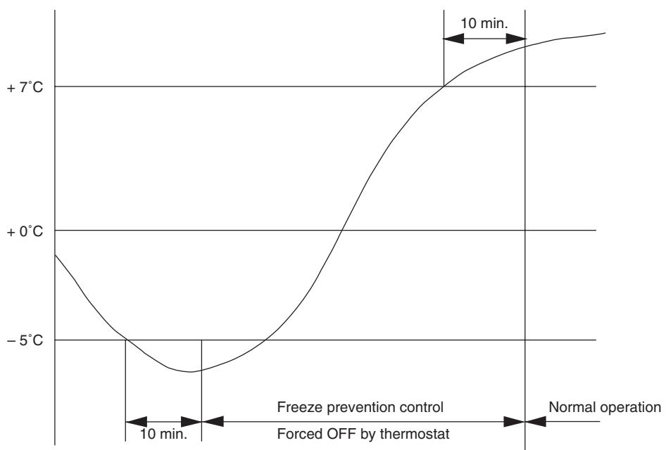
(R12940)
2.4 Hot Start Control (In Heating Operation Only)
Outline
At startup with thermostat ON or after the completion of defrosting in heating operation, the indoor unit fan is controlled to prevent cold air from blasting out and ensure startup capacity.
Detail

(R15421)
TH_2 : Temperature (^) detected with the gas thermistor TC : High pressure equivalent saturated temperature
3. Function of Thermistor
Illustrations are for 4-room models as representative and have 4 lines of indoor unit system (A D). 3-room models have 3 lines (A C) and 5-room models have 5 lines (A E).
Cooling Only Model

(R17248)
Heat Pump Model

(R17159)
(1) Outdoor Heat Exchanger Thermistor
- The outdoor heat exchanger thermistor is used for controlling the target discharge pipe temperature. The system sets the target discharge pipe temperature according to the outdoor and indoor heat exchanger temperature, and controls the outdoor electronic expansion valve opening so that the target discharge pipe temperature can be obtained.
- In cooling operation, the outdoor heat exchanger thermistor is used for detecting the disconnection of the discharge pipe thermistor. When the discharge pipe temperature becomes lower than the outdoor heat exchanger temperature, the discharge pipe thermistor is judged as disconnected.
- In cooling operation, the outdoor heat exchanger thermistor is used for high pressure protection.
| (2) Discharge Pipe Thermistor | 1. The discharge pipe thermistor is used for controlling discharge pipe temperature. If the discharge pipe temperature (used in place of the inner temperature of the compressor) rises abnormally, the operating frequency becomes lower or the operation halts.
2. The discharge pipe thermistor is used for detecting disconnection of the discharge pipe thermistor. |
| (3) Gas Pipe Thermistor | 1. In cooling operation, the gas pipe thermistor is used for gas pipe isothermal control. The system controls outdoor electronic expansion valve opening so that the gas pipe temperature in each room becomes equal. |
| (4) Indoor Heat Exchanger Thermistor | 1. The indoor heat exchanger thermistor is used for controlling the target discharge pipe temperature. The system sets the target discharge pipe temperature according to the outdoor and indoor heat exchanger temperature, and controls the outdoor electronic expansion valve opening so that the target discharge pipe temperature can be obtained.
2. In cooling operation, the indoor heat exchanger thermistor is used for freeze-up protection control. If the indoor heat exchanger temperature drops abnormally, the operating frequency becomes lower or the operation halts.
3. In cooling operation, the indoor heat exchanger thermistor is used for anti-icing function. If any of the following conditions are met in the room where operation halts, it is assumed as icing.
The conditions are
Tc ≤ -1°C
Ta - Tc ≥ 10°C
where Ta is the room temperature and Tc is the indoor heat exchanger temperature.
4. In heating operation, the indoor heat exchanger thermistor is used for heating peak-cut control. If the indoor heat exchanger temperature rises abnormally, the operating frequency becomes lower or the operation halts.
5. In heating operation, the indoor heat exchanger thermistor is used for detecting the disconnection of the discharge pipe thermistor. When the discharge pipe temperature becomes lower than the maximum indoor heat exchanger temperature, the discharge pipe thermistor is judged as disconnected.
6. When only one indoor unit is operating, the indoor heat exchanger thermistor is used for subcooling control. The actual subcool is calculated with the liquid pipe temperature and the indoor heat exchanger temperature. The system controls the outdoor electronic expansion valve openings to obtain the target subcool.
7. The indoor heat exchanger thermistor is used for wiring error check function. The refrigerant flows in order from the port A to detect the indoor heat exchanger temperature one by one, and then wiring and piping can be checked. |
| (5) Liquid Pipe Thermistor | 1. When only one indoor unit is in heating, the liquid pipe thermistor is used for subcooling control. The actual subcool is calculated with the liquid pipe temperature and the maximum indoor heat exchanger temperature. The system controls the outdoor electronic expansion valve openings to obtain the target subcool.
2. In heating operation, the liquid pipe thermistor is used for liquid pipes isothermal control. The system controls the outdoor electronic expansion valve opening so that the liquid pipe temperatures in each room becomes equal. |
| (6) Radiant Panel Thermistors | 1. The radiant panel thermistors are used for calculating radiant panel surface temperature. Due to structural and manufacturing restrictions, the radiant panel surface temperature cannot be controlled directly with a thermistor. Thermistors are mounted on the radiant panel piping in order to calculate the radiant panel surface temperature.
The indoor electronic expansion valve is controlled according to the radiant panel surface temperature.
2. The radiant panel thermistors are used for detecting malfunction of the indoor electronic expansion valve. |
4. Control Specification
4.1 Mode Hierarchy
Outline
There are 3 modes; normal operation mode, forced operation mode, and power transistor test mode for installation and servicing.
Detail
Cooling Only Model

(R14428)
Heat Pump Model

(R14248)

Unless specified otherwise, a dry operation command is regarded as cooling operation and a radiant operation command is regarded as heating operation.
- Indoor fan operation cannot be made in multiple indoor units. (A forced fan command is made during forced cooling operation.)
Determine Operation Mode
The system judges the operation mode command which is set by each room in accordance with the procedure, and determines the operation mode of the system.
The following procedure is taken when the modes conflict with each other.
1. The system follows the mode which is set first. (First-push, first-set)
2. For the rooms where the different mode is set, standby mode is activated. (The operation lamp blinks.)
4.2 Frequency Control
Outline
Frequency that corresponds to each room's capacity is determined according to the difference between the target temperature and the temperature of each room. The function is explained as follows.
- How to determine frequency
- Frequency command from an indoor unit (Difference between a room thermistor temperature and the target temperature)
- Frequency command from an indoor unit (The ranked capacity of the operating room)
- Frequency initial setting
- PI control

When the shift of the frequency is less than zero ( F < 0) by PI control, the target frequency is used as the command frequency.
Detail
How to Determine Frequency
The compressor's frequency is determined by taking the following steps.
For Cooling Only Model
1. Determine command frequency
Command frequency is determined in the following order of priority.
- Forced cooling
- Indoor frequency command
2. Determine upper limit frequency
- The minimum value is set as the upper limit frequency among the frequency upper limits of the following functions:
Compressor protection, input current, discharge pipe temperature, low Hz high pressure limit, freeze-up protection.
3. Determine lower limit frequency
- The maximum value is set as lower limit frequency among the frequency lower limits of the following functions:
Draft prevention, pressure difference upkeep.
4. Determine prohibited frequency
- There is a certain prohibited frequency such as a power supply frequency.
For Heat Pump Model
1. Determine command frequency
Command frequency is determined in the following order of priority.
- Limiting defrost control time
- Forced cooling / heating
- Indoor frequency command
2. Determine upper limit frequency
- The minimum value is set as upper limit frequency among the frequency upper limits of the following functions:
Compressor protection, input current, discharge pipe temperature, low Hz high pressure limit, heating peak-cut, freeze-up protection, defrost.
3. Determine lower limit frequency
- The maximum value is set as the lower limit frequency among the frequency lower limits of the following functions:
Four way valve operation compensation, draft prevention, pressure difference upkeep.
4. Determine prohibited frequency
- There is a certain prohibited frequency such as a power supply frequency.
Indoor Frequency Command (AD signal)
The difference between a room thermistor temperature and the target temperature is taken as the “ D signal” and is used for frequency command.
| Temperature difference (°C) | ΔD signal | Temperature difference (°C) | ΔD signal | Temperature difference (°C) | ΔD signal | Temperature difference (°C) | ΔD signal |
| -2.0 | *Th OFF | 0 | 4 | 2.0 | 8 | 4.0 | C |
| -1.5 | 1 | 0.5 | 5 | 2.5 | 9 | 4.5 | D |
| -1.0 | 2 | 1.0 | 6 | 3.0 | A | 5.0 | E |
| -0.5 | 3 | 1.5 | 7 | 3.5 | B | 5.5 | F |
Values depend on the type of indoor unit.
*Th OFF = Thermostat OFF
Indoor Unit Capacity (S value)
The capacity of the indoor unit is a "S" value and is used for frequency command.
| Ex: | Capacity | S value | Capacity | S value |
| 2.5 kW | 25 | 5.0 kW | 50 |
| 3.5 kW | 35 | 6.0 kW | 60 |
Frequency Initial Setting
When starting the compressor, or when conditions are varied due to the change of the operating room, the frequency must be initialized according to the total of a maximum D value of each room and a total value of Q ( Q ) of the operating room (the room in which the thermos is set to ON).
Q value: Indoor unit output determined from indoor unit volume, airflow rate and other factors.
PI Control (Determine Frequency Up / Down by D Signal)
1. P control
A total of the D value is calculated in each sampling time (20 seconds), and the frequency is adjusted according to its difference from the frequency previously calculated.
2. I control
If the operating frequency is not change more than a certain fixed time, the frequency is adjusted according to the D value.
When the D value is low, the frequency is lowered.
When the D value is high, the frequency is increased.
3. Limit of frequency increasing range
When the difference between input current and input current dropping value is less than 1.5 A, the frequency increasing range must be limited.
4. Frequency management when other controls are functioning
- When each frequency is dropping;
Frequency management is carried out only when the frequency drops.
For limiting lower limit
Frequency management is carried out only when the frequency rises.
5. Upper and lower limit of frequency by PI control
The frequency upper and lower limits are set according to the total of S values. When the indoor unit quiet operation commands come from more than one room or when the outdoor unit quiet operation commands come from all the rooms, the upper limit frequency is lower than the usual setting.
4.3 Controls at Mode Changing / Start-up
4.3.1 Preheating Operation
| Outline | The inverter operation in open phase starts with the conditions of the preheating command from the outdoor unit. |
| Detail | ON Condition
• When the outdoor temperature is below 10.5°C, the inverter operation in open phase starts.
OFF Condition
• When the outdoor temperature is higher than 12°C, the inverter operation in open phase stops. |
| 4.3.2 Four Way Valve Switching |
| Outline | In heating operation, current is conducted, and in cooling and defrosting operation, current is not conducted. In order to eliminate the switching sound, as the four way valve coil switches from ON to OFF when the heating is stopped, the OFF delay switch of the four way valve is carried out. |
| Detail | OFF delay switch of four way valve:
The four way valve coil is energized for 150 seconds after the operation is stopped. |
| 4.3.3 Four Way Valve Operation Compensation |
| Outline | At the beginning of the operation as the four way valve is switched, the pressure difference to activate the four way valve is acquired by having output frequency which is more than a certain fixed frequency, for a certain fixed time. |
| Detail | Starting Conditions
1. When starting the compressor for heating
2. When the operation mode changes from the previous time
3. When starting the compressor for defrosting
4. When starting the compressor for the first time after resetting with the power ON.
The lower limit of frequency keeps A Hz for 70 seconds with any conditions 1 through 4 above. |
| A (Hz) |
| 40/50/52/58 class | 48 |
| 68/75 class | 40 |
| 80/90 class | 28 |
4.3.4 3-Minute Standby
Turning on the compressor is prohibited for 3 minutes after turning off. (Except when defrosting.)
4.3.5 Compressor Protection Function
When turning the compressor from OFF to ON, the upper limit of frequency is set as follows. (The function is not used when defrosting.)

| 40/50/52/58 class | 68/75/80/90 class |
| A (Hz) | 55 | 55 |
| B (Hz) | 70 | 65 |
| C (Hz) | 85 | 80 |
| D (seconds) | 150 ~ 240 | 120 |
| E (seconds) | 180 | 200 |
| F (seconds) | 300 | 470 |
4.4 Discharge Pipe Temperature Control
Outline
The discharge pipe temperature is used as the internal temperature of the compressor. If the discharge pipe temperature rises above a certain level, the upper limit of frequency is set to keep the discharge pipe temperature from rising further.
Detail

(R14266)
| 40/50/52/58 class | 68/75/80/90 class |
| A (°C) | 110 | 120 |
| B (°C) | 103 | 111 |
| C (°C) | 102 | 109 |
| D (°C) | 100 | 107 |
| E (°C) | 95 | 107 |
| Zone | Control |
| Stop zone | When the temperature reaches the stop zone, the compressor stops. |
| Dropping zone | The upper limit of frequency decreases. |
| Keep zone | The upper limit of frequency is kept. |
| Reset zone | The upper limit of frequency is canceled. |
Outline
An input current is detected by the CT while the compressor is running, and the frequency upper limit is set from the input current.
In case of heat pump models, this control which is the upper limit control of the frequency takes priority over the lower limit control of four way valve operation compensation.
Detail

Frequency control in each zone
Stop zone
After 2.5 seconds in this zone, the compressor is stopped.
Dropping zone
The upper limit of the compressor frequency is defined as operation frequency - 2 Hz.
- After this, the output frequency is lowered by 2Hz every second until it reaches the keep zone.
Keep zone
The present maximum frequency goes on.
Reset zone
- Limit of the frequency is canceled.
Limitation of current dropping and stop value according to the outdoor temperature
- The current drops when outdoor temperature becomes higher than a certain level (depending on the model).
4.6 Freeze-up Protection Control
Outline
During cooling operation, the signals sent from the indoor unit control the operating frequency limitation and prevent freezing of the indoor heat exchanger. (The signal from the indoor unit is divided into zones.)
Detail
The operating frequency limitation is judged with the indoor heat exchanger temperature 2 seconds after operation starts and 30 seconds after the number of operation room is changed.

4.7 Heating Peak-cut Control
Outline
During heating operation, the indoor heat exchanger temperature determines the frequency upper limit to prevent abnormal high pressure.
Detail
The operating frequency is judged with the indoor heat exchanger temperature 2 minutes after the operation starts and F seconds after the number of operation room is changed.
The maximum value of the indoor heat exchanger temperature controls the following (excluding stopped rooms).

| Zone | Control |
| Stop zone | When the temperature reaches the stop zone, the compressor stops. |
| Dropping zone | The upper limit of frequency decreases. |
| Keep zone | The upper limit of frequency is kept. |
| Up zone | The upper limit of frequency increases. |
| Reset zone | The upper limit of frequency is canceled. |
| F (seconds) |
| When increase | 30 |
| When decrease | 2 |
4.8 Outdoor Fan Control
1. Fan ON control to cool down the electrical box
The outdoor fan is turned ON when the electrical box temperature is high while the compressor is OFF.
2. Fan OFF control during defrosting
The outdoor fan is turned OFF while defrosting.
3. Fan OFF delay when stopped
The outdoor fan is turned OFF 60 seconds after the compressor stops.
4. Fan speed control for pressure difference upkeep
The rotation speed of the outdoor fan is controlled for keeping the pressure difference during cooling operation with low outdoor temperature.
- When the pressure difference is low, the rotation speed of the outdoor fan is reduced.
- When the pressure difference is high, the rotation speed of the outdoor fan is controlled as well as normal operation.
5. Fan control when the number of heating room decreases
When the outdoor temperature is more than 10^ , the fan is turned off for 30 seconds.
6. Fan speed control during forced operation
The outdoor fan is controlled as well as normal operation during the forced operation.
7. Fan speed control during POWERFUL operation
The rotation speed of the outdoor fan is increased during the POWERFUL operation.
8. Fan speed control during indoor / outdoor unit quiet operation
The rotation speed of the outdoor fan is reduced by the command of the indoor / outdoor unit quiet operation.
9. Fan ON/OFF control when operation starts / stops
The outdoor fan is turned ON when the operation starts. The outdoor fan is turned OFF when the operation stops.
4.9 Liquid Compression Protection Function
Outline
In order to obtain the dependability of the compressor, the compressor is stopped according to the outdoor temperature and temperature of the outdoor heat exchanger.
Detail
Operation stops depending on the outdoor temperature
The compressor turns off under the conditions that the system is in cooling operation and outdoor temperature is below -12^ .
4.10 Defrost Control
Outline
Defrosting is carried out by the cooling cycle (reverse cycle). The defrosting time or outdoor heat exchanger temperature must be more than a certain value to finish.
Detail
Conditions for Starting Defrost
The starting conditions are determined with the outdoor temperature and the outdoor heat exchanger temperature.
The system is in heating operation.
The compressor operates for 6 minutes.
More than 38 minutes of accumulated time pass after the start of the operation, or ending the previous defrosting.
Conditions for Canceling Defrost
The target heat exchanger temperature as the canceling condition is selected in the range of 4 12^ according to the outdoor temperature.

(R17160)
| 40/50/52/58 class | 68/75 class | 80/90 class |
| A (Hz) | 62 | 54 | 39 |
| B (Hz) | 80 | 82 | 62 |
4.11 Low Hz High Pressure Limit
Outline
The upper limit of high pressure in a low Hz zone is set. The upper limit of the indoor heat exchanger temperature is also set by the operating frequency. Zones are divided into three, reset zone, keep zone, and dropping zone, and the frequency control is carried out according to each zone.
Detail

| 40/50/52/58/68/75 class | 80/90 class |
| A (°C) | 60 | 57 |
| B (°C) | 59 | 56 |
| C (°C) | 56 | 53 |

Note: Dropping: The system stops 2 minutes after staying in the dropping zone.
4.12 Outdoor Electronic Expansion Valve Control
Outline
The following items are included in the outdoor electronic expansion valve control. Outdoor electronic expansion valve is fully closed
- Outdoor electronic expansion valve is fully closed when turning on the power.
- Pressure equalizing control
Room Distribution Control
- Gas pipe isothermal control
- SC (subcooling) control
- Liquid pipe temperature control (with all ports connected and all rooms being air-conditioned)
- Liquid pipe temperature control for stopped rooms
- Dew prevention control for indoor rotor
Open Control
- Outdoor electronic expansion valve control when starting operation
- Outdoor electronic expansion valve control when the frequency changes
- Outdoor electronic expansion valve control for defrosting
- Outdoor electronic expansion valve control for oil recovery
- Outdoor electronic expansion valve control when a discharge pipe temperature is abnormally high
- Outdoor electronic expansion valve control when the discharge pipe thermistor is disconnected
- Outdoor electronic expansion valve control for indoor unit freeze-up protection
Feedback Control
- Target discharge pipe temperature control
Detail
The followings are the examples of the outdoor electronic expansion valve control which function in each operation mode.
| Operation pattern | ●: Holding Functions
—: No Functions | Gas pipe isothermal control | SC (subcooling) control | Control when the frequency changes | Control for abnormally high discharge
pipe temperature | Oil recovery control | Indoor freeze-up protection control | Liquid pipe temperature control | Liquid pipe temperature control for non-operating units | Dew prevention control for indoor rotor |
| When power is turned on | Fully closed when power is turned on | — | — | — | — | — | — | — | — | — |
| Cooling, 1 room operation | Open control when starting | — | — | — | ● | ● | ● | — | — | — |
| (Control of target discharge pipe temperature) | — | — | ● | ● | ● | ● | — | — | ● |
| Cooling, 2 rooms operation to Cooling, 4 rooms operation | Control when the operating room is changed | — | — | — | ● | ● | ● | — | — | ● |
| (Control of target discharge pipe temperature) | ● | — | ● | ● | ● | ● | — | — | ● |
| Stop | Pressure equalizing control | — | — | — | — | — | — | — | — | — |
| Heating, 1 room operation | Open control when starting | — | — | — | ● | — | — | — | — | — |
| (Control of target discharge pipe temperature) | — | ●
★2 | ● | ● | — | — | ●
★1 | ●
★3 | — |
| Heating, 2 rooms operation | Control when the operating room is changed | — | — | — | ● | — | — | — | — | — |
| (Control of target discharge pipe temperature) | — | ●
★2 | ● | ● | — | — | ●
★1 | ●
★3 | — |
| (Defrost control) | — | — | — | — | — | — | — | — | — |
| Stop | Pressure equalizing control | — | — | — | — | — | — | — | — | — |
| Heating operation | Open control when starting | — | — | — | ● | — | — | — | — | — |
| Continue | — | ●
★2 | — | — | — | — | ●
★1 | ●
★3 | — |
| Control of discharge pipe thermistor disconnection |
| Stop | Pressure equalizing control | — | — | — | — | — | — | — | — | — |
(R16007)
1 : When all the indoor units are operating, "liquid pipe temperature control" is conducted.
2 : "SC (subcooling) control" is conducted for the operating indoor units, when some of the units are not operating.
3 : "Liquid pipe temperature control for stopped room" is conducted for the non-operating indoor units.
4.12.1 Fully Closing with Power on
The outdoor electronic expansion valve is initialized when the power is turned on. The opening position is set and the pressure equalization is developed.
4.12.2 Pressure Equalizing Control
When the compressor is stopped, the pressure equalizing control is activated. The outdoor electronic expansion valve opens, and develops the pressure equalization.
4.12.3 Opening Limit Control
| Outline | A maximum and minimum opening of the outdoor electronic expansion valve are limited. |
| Detail | ■ A maximum outdoor electronic expansion valve opening in the operating room: 450 pulses
■ A minimum outdoor electronic expansion valve opening in the operating room: 75 pulses
The outdoor electronic expansion valve is fully closed in the room where cooling is stopped and is opened at a fixed degree during defrosting. |
4.12.4 Starting Operation Control / Changing Operation Room
The outdoor electronic expansion valve opening is controlled when the operation starts, and prevents superheating or liquid compression.
4.12.5 Control when the Frequency Changes
When the target discharge pipe temperature control is active, if the target frequency is changed to a specified value in a certain time period, the target discharge pipe temperature control is canceled and the target opening of the outdoor electronic expansion valve is changed.
4.12.6 Oil Recovery Function
| Outline | The outdoor electronic expansion valve opening in the cooling stopped room is set as to open for a certain time at a specified interval so that the oil in the cooling stopped room may not be accumulated. |
| Detail | During cooling operation, every 1 hour continuous operation, the outdoor electronic expansion valves in the operation stopped room is opened by 80 pulses for specified time. |
4.12.7 High Discharge Pipe Temperature Control
When the compressor is operating, if the discharge pipe temperature exceeds a certain value, the outdoor electronic expansion valve opens and the refrigerant runs to the low pressure side. This procedure lowers the discharge pipe temperature.
4.12.8 Control for Disconnection of the Discharge Pipe Thermistor
Outline
The disconnection of the discharge pipe thermistor is detected by comparing the discharge pipe temperature with the condensing temperature. If the discharge pipe thermistor is disconnected, the outdoor electronic expansion valve opens according to the outdoor temperature and the operation frequency, and operates for a specified time, and then stops.
After 3 minutes, the operation restarts and checks if the discharge pipe thermistor is disconnected. If the discharge pipe thermistor is disconnected, the system stops after operating for a specified time.
If the disconnection is detected repeatedly, the system is shut down. When the compressor runs for 60 minutes without any error, the error counter is reset.
Detail
Detect Disconnection
When the starting control (660 ~ 810 seconds) finishes, the following adjustment is made.
- When the operation mode is cooling
When the following condition is fulfilled, the discharge pipe thermistor disconnection is ascertained.
Discharge pipe temperature +6^ < outdoor heat exchanger temperature
- When the operation mode is heating
When the following condition is fulfilled, the discharge pipe thermistor disconnection is ascertained.
Discharge pipe temperature +6^ < highest indoor heat exchanger temperature
Adjustment when the thermistor is disconnected
When the disconnection is ascertained, the compressor continues operation for 9 minutes and then stops.
If the compressor stops repeatedly, the system is shut down.
4.12.9 Gas Pipe Isothermal Control During Cooling
When the units are operating in multiple rooms, the gas pipe temperature is detected and the outdoor electronic expansion valve opening is adjusted so that the temperature of the gas pipe in each room becomes equal.
- When the gas pipe temperature > the average gas pipe temperature, open the outdoor electronic expansion valve in that room
- When the gas pipe temperature < the average gas pipe temperature, close the outdoor electronic expansion valve in that room
The temperatures are monitored every 40 seconds.
4.12.10 SC (Subcooling) Control
Outline
The liquid pipe temperature and the heat exchanger temperature are detected and the outdoor electronic expansion valve opening is compensated so that the SC of each room becomes the target SC.
- When the actual SC is > target SC, open the outdoor electronic expansion valve of the room.
- When the actual SC is < target SC, close the outdoor electronic expansion valve of the room.
Detail
Start Conditions
After finishing the starting control (660 ~ 810 seconds), (all) the outdoor electronic expansion valve(s) for the operating room is/are controlled.
Determine Outdoor Electronic Expansion Valve Opening
The outdoor electronic expansion valve opening is adjusted so that the temperature difference between the maximum heat exchanger temperature of connected room and the liquid pipe temperature thermistor becomes constant.
4.12.11Target Discharge Pipe Temperature Control
The target discharge pipe temperature is obtained from the indoor and outdoor heat exchanger temperature, and the outdoor electronic expansion valve opening is adjusted so that the actual discharge pipe temperature becomes close to the target discharge pipe temperature. (Indirect SH (superheating) control using the discharge pipe temperature)
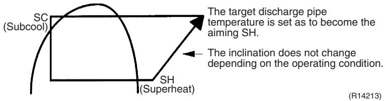
The outdoor electronic expansion valve opening and the target discharge pipe temperature are adjusted every 20 seconds. The target discharge pipe temperature is controlled by indoor heat exchanger temperature and outdoor heat exchanger temperature. The opening degree of the outdoor electronic expansion valve is controlled by the followings.
Target discharge pipe temperature
Actual discharge pipe temperature
Previous discharge pipe temperature
4.13 Malfunctions
4.13.1 Sensor Malfunction Detection
Sensor malfunction may occur either in the thermistor or current transformer (CT) system.
Relating to Thermistor Malfunction
- Outdoor heat exchanger thermistor
- Discharge pipe thermistor
- Radiation fin thermistor
- Gas pipe thermistor
- Outdoor temperature thermistor
- Liquid pipe thermistor

Relating to CT Malfunction
Refer to "CT or related abnormality" on page 315 for detail.
4.13.2 Detection of Overcurrent and Overload
| Outline | In order to protect the inverter, an excessive output current is detected and the OL temperature is observed to protect the compressor. |
| Detail | ■ If the inverter current exceeds 14 ~ 20 A (depending on the model), the system shuts down the compressor. |
If the OL (compressor head) temperature exceeds 120 130^ , the compressor stops.
4.13.3 Refrigerant Shortage Control
| Outline | I: Detecting by power consumption
If the power consumption is below the specified value and the frequency is higher than the specified frequency, it is regarded as refrigerant shortage.
The power consumption is low comparing with that in the normal operation when refrigerant is insufficient, and refrigerant shortage is detected by checking power consumption. |

II: Detecting by discharge pipe temperature
If the discharge pipe temperature is higher than the target discharge pipe temperature, and the outdoor electronic expansion valve is fully open for more than the specified time, it is regarded as refrigerant shortage.


Refer to "Refrigerant shortage" on page 296 for detail.
4.13.4 Anti-icing Function
During cooling, if the indoor heat exchanger temperature in the operation stopped room becomes below the specified temperature for the specified time, the outdoor electronic expansion valve is opened in the operation stopped room as specified, and the fully closed operation is carried out. After this, if freezing abnormality occurs more than specified time, the system shuts down as the system abnormality.
Part 5 Operation Manual
- System Configuration 125
- RA Indoor Unit 126
2.1 FTXG, FTXS-K, CTXS, FVXG Series - ARC466A1, A2, A6 126
2.2 FTXS-J, FTXS-G, FVXS Series - ARC452A1, A3 178
2.3 FLXS, FDXS Series - ARC433B67, B69 218
- SA Indoor Unit 233
3.1 BRC1D528 233
1. System Configuration
After installation and trial operation of the room air conditioner are completed, the air conditioner should be handled and operated as described in the following pages. Every user should be informed on the correct method of operation and how to check if it can cool (or heat) well, and how to use it efficiently.
Providing instructions to the user can reduce requests for servicing by 80% . However proficient the installation and operating functions of the air conditioning system are, the customer may fault either the room air conditioner or its installation work when it is actually due to improper handling. The installation work and the handing-over of the unit can only be considered completed when its handling has been fully explained to the user without using technical terms, and while imparting full knowledge of the equipment.
2. RA Indoor Unit
2.1 FTXG, FTXS-K, CTXS, FVXG Series - ARC466A1, A2, A6
2.1.1 Manual Contents and Reference Page
| Model Series | Wall Mounted Type | Floor Standing Type |
| FTXG25-50JV1BW(A) | FTXS20/25K2V1B
CTXS15/35K2V1B | FVXG25-50K2V1B |
| Read Before Operation | | | |
| Names of Parts | 127 | 131 | 135 |
| Preparation before Operation | 139 ★2 | 139 ★2 | 139 |
| Operation | | | |
| AUTO · DRY · COOL · HEAT · FAN Operation | 141 | 143 | 145 |
| RADIANT Operation | — | — | 146 |
| Temperature Setting | — | — | 147 |
| Adjusting the Airflow Direction and Rate | 148 | 150 | 152 |
| COMFORT AIRFLOW Operation | 154 ★1 | 154 | — |
| INTELLIGENT EYE Operation | 155 ★1 | 155 | — |
| POWERFUL Operation | 157 ★1 | 157 | 158 |
| OUTDOOR UNIT QUIET Operation | 159 ★2 | 159 ★2 | 159 |
| ECONO Operation | 160 ★2 | 160 ★2 | 160 |
| OFF TIMER Operation | 161 | 162 | 163 |
| ON TIMER Operation | 164 | 165 | 166 |
| WEEKLY TIMER Operation | 167 ★2 | 167 ★2 | 167 |
| Note for Multi System | 173 | 173 | 173 |
| Quick Reference | 175 ★1 | 176 | 177 |
| Drawing No. | 3P255639-2A (Reference) | 3P297033-1 | 3P276869-1 |
1 Illustrations are for FTXS-K and CTXS-K series as representative.
2 : Illustrations are for FVXG series as representative.
2.1.2 Name of Parts
FTXG25/35/50JV1BW(A)
Name of Parts
Indoor Unit
- Appearance of the indoor unit may differ.
Front panel
Air outlet
Louvers (vertical blades)
- The louvers are inside of the air outlet.
Flaps (horizontal blades)
Display
INTELLIGENT EYElamp (green)
Signal receiver and Indoor unit ON/OFF switch
Signal receiver
- It receives signals from the remote controller.
- When the unit receives a signal, you will hear a beep sound.
| Case | Sound type |
| Operation start | beep-beep |
| Setting changed | beep |
| Operation stop | long beep |

Multi-monitor lamp and TIMER lamp
Multi-monitor lamp
- The lamp colour changes according to the operation.
| Operation | Multi-monitor lamp |
| AUTO | Red/Blue |
| DRY | Green |
| COOL | Blue |
| HEAT | Red |
| FAN | White |
| TIMER | Orange |
Indoor unit ON/OFF switch
- Press this switch once to start operation. Press once again to stop it.
- The operation mode refers to the following table.
| Mode | Temperature setting | Airflow rate |
| AUTO | 25°C | AUTO |
- This switch is useful when the remote controller is missing.
TIMER lamp
- When operation by timer has been set, the multi-monitor lamp periodically changes to orange. After lighting orange for about 5 seconds, it returns to the colour of the operation mode. The multi-monitor lamp will turn orange on and off in cyclic manner while the air conditioner is not in operation.
TIMER lamp colour : For COOL

TIMER lamp colour
| DRY: | Green → Orange |
| COOL: | Blue → Orange |
| HEAT: | Red → Orange |
| FAN: | White → Orange |
| Stop: | Off → Orange |

Open the front panel

Titanium apatite photocatalytic air-purifying filter
Name of Parts
Remote Controller
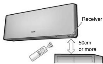
Signal transmitter
- To use the remote controller, aim the transmitter at the indoor unit. If there is anything to block signals between the unit and the remote controller, such as a curtain, the unit will not operate.
- Do not drop the remote controller. Do not get it wet.
- The maximum distance for communication is approx. 6m.
Make sure that there are no obstacles within 50cm under the signal receiver.
Such obstacles, if any, may have an adverse influence on the reception performance of the receiver and the reception distance may be shortened.
- It selects the airflow rate setting.

Open the front cover

FTXS20/25K2V1B, CTXS15/35K2V1B

Name of Parts

Indoor unit ON/OFF switch
- Press this switch once to start operation. Press once again to stop it.
- The operation mode refers to the following table.
| Mode | Temperature setting | Airflow rate |
| AUTO | 25°C | AUTO |
- This switch is useful when the remote controller is missing.

Open the front panel
Name of Parts
Remote Controller

Signal transmitter
- To use the remote controller, aim the transmitter at the indoor unit. If there is anything to block signals between the unit and the remote controller, such as a curtain, the unit will not operate.
- Do not drop the remote controller. Do not get it wet.
- The maximum distance for communication is approx. 7m.
- It selects the airflow rate setting.
Model ARC466A6
Display (LCD)
- It displays the current settings. (In this illustration, each section is shown with its displays on for the purpose of explanation.)
- It changes the temperature setting.
- Press this button once to start operation.
Press once again to stop it.
Front cover
Open the front cover

FVXG25/35/50K2V1B
Name of Parts
Indoor Unit
Display

- It detects the air temperature around the unit.
Signal receiver and Indoor unit ON/OFF switch
Signal receiver
- It receives signals from the remote controller.
- When the unit receives a signal, you will hear a beep sound.
| Case | Sound type |
| Operation start | beep-beep |
| Setting changed | beep |
| Operation stop | long beep |
Indoor unit ON/OFF switch
- Press this switch once to start operation.
Press once again to stop it.
The operation mode refer to the following table.
| Mode | Temperature setting | Airflow rate |
| AUTO | 25°C | AUTO |
- This switch is useful when the remote controller is missing.


Open the front panel
Name of Parts
Remote Controller

Signal transmitter
- To use the remote controller, aim the transmitter at the indoor unit. If there is anything to block signals between the unit and the remote controller, such as a curtain, the unit will not operate.
- Do not drop the remote controller. Do not get it wet.
- The maximum distance for communication is approximately 7m .
- It selects the airflow rate setting.
Model ARC466A2
Display (LCD)
- It displays the current settings. (In this illustration, each section is shown with its displays on for the purpose of explanation.)
TEMPERATURE
- It changes the temperature setting.
- Press this button once to start operation.
Press once again to stop it.
Front cover

Open the front cover
2.1.3 Preparation before Operation
Preparation before Operation
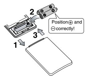
To set the batteries
- Slide the front cover to take it off.
- Set two dry batteries AAA.LR03 (alkaline).
- Set the front cover as before.

To fix the remote controller holder on the wall
- Choose a place from where the signals reach the unit.
- Fix the holder to a wall, a pillar, or similar location with the screws procured locally
- Place the remote controller in the remote controller holder.
To set the luminance of the display
- The luminance of the indoor unit display can be set.


NOTE
Notes on batteries
- When replacing the batteries, use batteries of the same type, and replace both old batteries together.
- When the system is not used for a long time, take the batteries out.
The batteries will last for approximately 1 year. If the remote controller display begins to fade and the degradation of reception performance occurs within a year, however, replace both batteries with new, size AAA.LR03 (alkaline).
- The attached batteries are provided for the initial use of the system.
The usable period of the batteries may be short depending on the manufactured date of the air conditioner.
Notes on remote controller
- Never expose the remote controller to direct sunlight.
- Dust on the signal transmitter or receiver will reduce the sensitivity. Wipe off dust with soft cloth.
- Signal communication may be disabled if an electronic-starter-type fluorescent lamp (such as inverter-type lamps) is in the room. Consult the shop if that is the case.
If the remote controller signals happen to operate another appliance, move that appliance to somewhere else, or consult the service shop.

Turn the breaker on
- After the power is turned on, the flap of the indoor unit opens and closes once to set the reference position.
To set the clock
- Press .


“①”blinks.
-
Press Select to set the clock to the present time.
-
Holding down or rapidly increases or decreases the time display.
-
Press .
-
Point the remote controller at the indoor unit when pressing the buttons.

"..." blinks.
NOTE
Note on setting the clock
- If the indoor unit's internal clock is not set to the correct time, the ON TIMER, OFF TIMER and WEEKLY TIMER will not operate punctually.
2.1.4 AUTO · DRY · COOL · HEAT · FAN Operation
FTXG25/35/50JV1BW(A)

AUTO · DRY · COOL · HEAT · FAN Operation

The air conditioner operates with the operation mode of your choice.
From the next time on, the air conditioner will operate with the same operation mode.
To start operation
1. Press Mode and select an operation mode.
Each pressing of the button advances the mode setting in sequence.

2. Press

- “ON” is displayed on the LCD.
- The multi-monitor lamp lights up.
The colour of the lamp varies depending on the operation mode.

| Operation | Multi-monitor lamp |
| AUTO | Red/Blue |
| DRY | Green |
| COOL | Blue |
| HEAT | Red |
| FAN | White |
To stop operation
Press () again.
- “ON” disappears from the LCD.
- The multi-monitor lamp goes off.
NOTE
| MODE | Notes on each operation mode |
| HEAT | ·Since this air conditioner heats the room by taking heat from outdoor air to indoors, the heating capacity becomes smaller in lower outdoor temperatures. If the heating effect is insufficient, it is recommended to use another heating appliance in combination with the air conditioner.
·The heat pump system heats the room by circulating hot air around all parts of the room. After the start of HEAT operation, it takes some time before the room gets warmer.
·In HEAT operation, frost may occur on the outdoor unit and lower the heating capacity. In that case, the system switches into defrosting operation to take away the frost.
·During defrosting operation, hot air does not flow out of indoor unit. |
| COOL | ·This air conditioner cools the room by releasing the heat in the room outside.
Therefore, the cooling performance of the air conditioner may be degraded if the outdoor temperature is high |
| DRY | ·The computer chip works to rid the room of humidity while maintaining the temperature as much as possible. It automatically controls temperature and airflow rate, so manual adjustment of these functions is unavailable. |
| AUTO | ·In AUTO operation, the system selects an appropriate operation mode (COOL or HEAT) based on the room and outside temperatures and starts the operation.
·The system automatically reselects setting at a regular interval to bring the room temperature to user-setting level. |
| FAN | ·This mode is valid for fan only. |

To change the temperature setting
Press

- The displayed items on the LCD will change whenever either one of the buttons is pressed.
| COOL operation | HEAT operation | AUTO operation | DRY or FAN operation |
| 18-32°C | 10-30°C | 18-30°C | The temperature setting is not variable. |
| Press▲to raise the temperature and press▼to lower the temperature. |
Operating conditions
Recommended temperature setting
For cooling: 26 - 28^
For heating: 20 - 24^
Tips for saving energy
- Be careful not to cool (heat) the room too much.
Keeping the temperature setting at a moderate level helps save energy.
- Cover windows with a blind or a curtain.
Blocking sunlight and air from outdoors increases the cooling (heating) effect.
Clogged air filters cause inefficient operation and waste energy. Clean them once in about every 2 weeks.
Notes on the operating conditions
- The outdoor unit consumes some power to have its electric components work even while it is not operating.
Connecting outdoor unit RXG25/35: 1-15W
Other outdoor units: 15-20W
The outdoor unit consumes 40 to 55W of power at the time of compressor preheating.
- If you are not going to use the air conditioner for a long period, for example in spring or autumn, turn the breaker off.
- Use the air conditioner in the following conditions.
| MODE | Operating conditions | If operation is continued out of this range |
| COOL | Outdoor temperature: <2/3/4/5MXS> -10-46°C
<RXG> -10-46°C
Indoor temperature: 18-32°C
Indoor humidity: 80% max. | • A safety device may work to stop the operation.
(In multi system, it may work to stop the operation of the outdoor unit only.)
• Condensation may occur on the indoor unit and drip. |
| HEAT | Outdoor temperature: <2MXS> -10-24°C
<3/4/5MXS> -15-24°C
<RXG> -15-24°C
Indoor temperature: 10-30°C | • A safety device may work to stop the operation. |
| DRY | Outdoor temperature: <2/3/4/5MXS> -10-46°C
<RXG> -10-46°C
Indoor temperature: 18-32°C
Indoor humidity: 80% max. | • A safety device may work to stop the operation.
• Condensation may occur on the indoor unit and drip. |
- Operation outside this humidity or temperature range may cause a safety device to disable the system.
FTXS20/25K2V1B, CTXS15/35K2V1B

AUTO · DRY · COOL · HEAT · FAN Operation

The air conditioner operates with the operation mode of your choice.
From the next time on, the air conditioner will operate with the same operation mode.
To start operation
1. Press Mode and select an operation mode.
Each pressing of the button advances the mode setting in sequence.
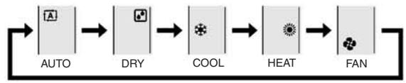
2. Press

- “ON” is displayed on the LCD.
- The OPERATION lamp lights green.

Display
To stop operation
Press again.
ON disappears from the LCD.
- The OPERATION lamp goes off.
NOTE
| MODE | Notes on each operation mode |
| HEAT | • Since this air conditioner heats the room by taking heat from outdoor air to indoors, the heating capacity becomes smaller in lower outdoor temperatures. If the heating effect is insufficient, it is recommended to use another heating appliance in combination with the air conditioner.
• The heat pump system heats the room by circulating hot air around all parts of the room. After the start of HEAT operation, it takes some time before the room gets warmer.
• In HEAT operation, frost may occur on the outdoor unit and lower the heating capacity. In that case, the system switches into defrosting operation to take away the frost.
• During defrosting operation, hot air does not flow out of indoor unit. |
| COOL | • This air conditioner cools the room by releasing the heat in the room outside.
Therefore, the cooling performance of the air conditioner may be degraded if the outdoor temperature is high |
| DRY | • The computer chip works to rid the room of humidity while maintaining the temperature as much as possible. It automatically controls temperature and airflow rate, so manual adjustment of these functions is unavailable. |
| AUTO | • In AUTO operation, the system selects an appropriate operation mode (COOL or HEAT) based on the room and outside temperatures and starts the operation.
• The system automatically reselects setting at a regular interval to bring the room temperature to user-setting level. |
| FAN | • This mode is valid for fan only. |

To change the temperature setting
Press

- The displayed items on the LCD will change whenever either one of the buttons is pressed.
| COOL operation | HEAT operation | AUTO operation | DRY or FAN operation |
| 18-32°C | 10-30°C | 18-30°C | The temperature setting is not variable. |
| Press▲to raise the temperature and press▼to lower the temperature. |
Operating conditions
Recommended temperature setting
For cooling: 26 - 28^
For heating: 20 - 24^
Tips for saving energy
- Be careful not to cool (heat) the room too much.
Keeping the temperature setting at a moderate level helps save energy.
- Cover windows with a blind or a curtain.
Blocking sunlight and air from outdoors increases the cooling (heating) effect.
Clogged air filters cause inefficient operation and waste energy. Clean them once in about every 2 weeks.
Notes on the operating conditions
- The outdoor unit consumes some power to have its electric components work even while it is not operating. Connecting outdoor unit RXS20/25: 1-15W
Other outdoor units: 15-20W
The outdoor unit consumes 40 to 55W of power at the time of compressor preheating.
- If you are not going to use the air conditioner for a long period, for example in spring or autumn, turn the breaker off.
- Use the air conditioner in the following conditions.
| MODE | Operating conditions | If operation is continued out of this range |
| COOL | Outdoor temperature: <2MXS> 10-46°C<3/4/5MXS> -10-46°C<RXS> -10-46°CIndoor temperature: 18-32°CIndoor humidity: 80% max. | • A safety device may work to stop the operation.(In multi system, it may work to stop the operation of the outdoor unit only.)• Condensation may occur on the indoor unit and drip. |
| HEAT | Outdoor temperature: <2/3/4/5MXS> -15-24°C<RXS> -15-24°CIndoor temperature: 10-30°C | • A safety device may work to stop the operation. |
| DRY | Outdoor temperature: <2MXS> 10-46°C<3/4/5MXS> -10-46°C<RXS> -10-46°CIndoor temperature: 18-32°CIndoor humidity: 80% max. | • A safety device may work to stop the operation.• Condensation may occur on the indoor unit and drip. |
- Operation outside this humidity or temperature range may cause a safety device to disable the system.
FVXG25/35/50K2V1B

AUTO · DRY · COOL · HEAT · FAN Operation

The air conditioner operates with the operation mode of your choice. From the next time on, the air conditioner will operate with the same operation mode.
To start operation
1. Press Mode and select an operation mode.
Each pressing of the button advances the mode setting in sequence.

2. Press
"ON" is displayed on the LCD.
- The OPERATION lamp lights green.
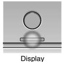
To stop operation

- "ON" disappears from the LCD.
- The OPERATION lamp goes off.
NOTE
| MODE | Notes on each operation mode |
| HEAT | ·Since this air conditioner heats the room by taking heat from outdoor air to indoors, the heating capacity becomes smaller in lower outdoor temperatures. If the heating effect is insufficient, it is recommended to use another heating appliance in combination with the air conditioner.
·The heat pump system heats the room by circulating hot air around all parts of the room. After the start of HEAT operation, it takes some time before the room gets warmer.
·In HEAT operation, frost may occur on the outdoor unit and lower the heating capacity. In that case, the system switches into defrosting operation to take away the frost.
·During defrosting operation, hot air does not flow out of indoor unit. |
| COOL | ·This air conditioner cools the room by releasing the heat in the room outside.
Therefore, the cooling performance of the air conditioner may be degraded if the outdoor temperature is high.
·When the outdoor temperature is lower than 10°C, do not use COOL operation. If the operation is used when the outdoor temperature is lower than 10°C, the protective function of the main unit works and this disables the operation. |
| DRY | ·The computer chip works to rid the room of humidity while maintaining the temperature as much as possible. It automatically controls temperature and airflow rate, so manual adjustment of these functions is unavailable. |
| AUTO | ·In AUTO operation, the system selects an appropriate operation mode (COOL or HEAT) based on the room and outside temperatures and starts the operation.
·The system automatically reselects setting at a regular interval to bring the room temperature to user-setting level. |
| FAN | ·This mode is valid for fan only. |
2.1.5 RADIANT Operation

RADIANT Operation

The RADIANT operation provides a comfortable environment with quiet and currentless heating operation in addition to the HEAT operation mode. The RADIANT operation has 2 operation modes.
To start RADIANT operation
1. Press Mode and select an HEAT operation.
Each pressing of the button advances the mode setting in sequence.

" ” is displayed on the LCD.
2. Press and select a RADIANT operation.
- "55" is displayed on the LCD.
- The RADIANT lamp lights red.
- This button can be used only in the HEAT operation mode.
- When the RADIANT operation starts, the temperature of the radiant panel increases.


Display

RADIANT operation with HEAT
■ RADIANT1
- Use this operation when the difference between the set temperature and indoor temperature is large, or to warm up the room quickly.

RADIANT operation
RADIANT2
- Use this operation to prioritize quiet and currentless heating operation, or when the noise from RADIANT1 operation bothers you. The gentle breeze operation starts from the beginning.
CAUTION
- During the RADIANT operation, the surface temperature of the panel will be about 55^ at maximum. Even after the RADIANT operation is finished, the surface temperature of the panel of the air conditioner stays hot for a while. Do not touch the air conditioner until the surface temperature of the panel decreases. Be careful that children do not touch the surface of the panel.
NOTE
Notes on RADIANT operation
- If RADIANT2 operation does not warm up the room, use HEAT or RADIANT1 operation.
- RADIANT1 can be used with POWERFUL operation. RADIANT2 cannot be used with the POWERFUL operation.
- This operation may not warm up the room adequately depending on conditions such as an extremely low outside temperature and lack of adequate performance.
- The RADIANT operation uses the auto fan speed, so the airflow rate cannot be changed.
- When the indoor units are connected using a multi system, please refer to "Selecting the operation mode" in note for multi system.
2.1.6 Temperature Setting

Temperature Setting

To change the temperature setting
Press Temp
- The displayed items on the LCD will change whenever either one of the buttons is pressed.
| COOL operation | HEAT or RADIANT operation | AUTO operation | DRY or FAN operation |
| 18-32°C | 10-30°C | 18-30°C | The temperature setting is not variable. |
| Press▲ to raise the temperature and press▼ to lower the temperature. |
Operating conditions
Recommended temperature setting
For cooling: 26 - 28^
For heating: 20 - 24^
Tips for saving energy
- Be careful not to cool (heat) the room too much.
Keeping the temperature setting at a moderate level helps save energy.
- Cover windows with a blind or a curtain.
Blocking sunlight and air from outdoors increases the cooling (heating) effect.
Clogged air filters cause inefficient operation and waste energy. Clean them once in about every 2 weeks.
Notes on the operating conditions
- The outdoor unit consumes some power to have its electric components work even while it is not operating.
Connecting outdoor unit RXG25/35: 1-15W
Other outdoor units: 15-20W
The outdoor unit consumes 40 to 55W of power at the time of compressor preheating.
- If you are not going to use the air conditioner for a long period, for example in spring or autumn, turn the breaker off.
- Use the air conditioner in the following conditions.
| MODE | Operating conditions | If operation is continued out of this range |
| COOL | Outdoor temperature: <2/3/4/5MXS> 10-46°C
<RXG> 10-46°C
Indoor temperature: 18-32°C
Indoor humidity: 80% max. | • A safety device may work to stop the operation.
(In multi system, it may work to stop the operation of the outdoor unit only.)
• Condensation may occur on the indoor unit and drip. |
| HEAT or RADIANT | Outdoor temperature: <2MXS> -10-24°C
<3/4/5MXS> -15-24°C
<RXG> -15-24°C
Indoor temperature: 10-30°C | • A safety device may work to stop the operation. |
| DRY | Outdoor temperature: <2/3/4/5MXS> 10-46°C
<RXG> 10-46°C
Indoor temperature: 18-32°C
Indoor humidity: 80% max. | • A safety device may work to stop the operation.
• Condensation may occur on the indoor unit and drip. |
- Operation outside this humidity or temperature range may cause a safety device to disable the system.
2.1.7 Adjusting the Airflow Direction and Rate
FTXG25/35/50JV1BW(A)

Adjusting the Airflow Direction and Rate

You can adjust the airflow direction to increase your comfort.
To start auto swing
Upper and lower airflow direction
Press

- " " is displayed on the LCD.
- The flaps (horizontal blades) will begin to swing.

To set the flaps at desired position
- This function is effective while flaps are in auto swing mode.
Press Swing when the flaps have reached the desired position.
- "C" disappears from the LCD.
To adjust the louvers at desired position
Hold the knob and move the louvers.
- You will find a knob on the left-side and the right-side blades.
- When the unit is installed in the corner of a room, the direction of the louvers (vertical blades) should be facing away from the wall. If they face the wall, the wall will block off the wind, causing the cooling (or heating) efficiency to drop.
- If the flaps are in the way, press 4 Swing on the remote controller to move the flaps out of the way and then adjust the louvers.


To adjust the airflow rate setting

- When the airflow is set to "坐", indoor unit quiet operation will start and the noise from the unit will become quieter.
- In indoor unit quiet operation, the airflow rate is set to a weak level.
- In DRY mode, the airflow rate setting is not variable.
NOTE
Note on the angles of the flaps
- The flaps swinging range depends on the operation. (See the figure.)
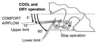


Note on airflow rate setting
- At smaller airflow rates, the cooling (heating) effect is also smaller.
- If the air conditioner is operated in COOL or DRY operation with the flaps kept stopped in the downward direction, the flaps will automatically start operating in approximately an hour in order to prevent dew condensation.

CAUTION
- Always use a remote controller to adjust the angles of the flaps. If you attempt to move it forcibly with hand when it is swinging, the mechanism may be broken.
- Be careful when adjusting the louvers.
Inside the air outlet, a fan is rotating at a high speed.
FTXS20/25K2V1B, CTXS15/35K2V1B

Adjusting the Airflow Direction and Rate

You can adjust the airflow direction to increase your comfort.
To start auto swing
Upper and lower airflow direction
Press
Swing
- "C" is displayed on the LCD.
- The flap (horizontal blade) will begin to swing.

To set the flap at desired position
- This function is effective while flap is in auto swing mode.
Press Swing when the flap has reached the desired position.

disappears from the LCD.
To adjust the louvers at desired position
Hold the knob and move the louvers.
- You will find a knob on the left-side and the right-side blades.
- When the unit is installed in the corner of a room, the direction of the louvers (vertical blades) should be facing away from the wall.

If they face the wall, the wall will block off the wind, causing the cooling (or heating) efficiency to drop.
- If the flap is in the way, press (Swing) on the remote controller to move the flap out of the way and then adjust the louvers.
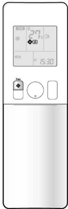
To adjust the airflow rate setting

Each pressing of advances the airflow rate setting in sequence.

- When the airflow is set to " ", indoor unit quiet operation will start and the noise from the unit will become quieter.
- In indoor unit quiet operation, the airflow rate is set to a weak level.
- If the temperature does not reach the desired point in the indoor unit quiet operation, change the airflow rate setting.
- In DRY mode, the airflow rate setting is not variable.
NOTE
Notes on the angles of the flap
- The flap swinging range depends on the operation. (See the figure.)


- If the air conditioner is operated in COOL or DRY operation with the flap kept stopped in the downward direction, the flap will automatically start operating in approximately an hour in order to prevent dew condensation.
Note on airflow rate setting
- At smaller airflow rates, the cooling (heating) effect is also smaller.
CAUTION
- Always use a remote controller to adjust the angles of the flap. If you attempt to move the flap and louvers forcibly with hand when they are swinging, the mechanism may be broken.
- Be careful when adjusting the louvers. Inside the air outlet, a fan is rotating at a high speed.
FVXG25/35/50K2V1B

Adjusting the Airflow Direction and Rate
You can adjust the airflow direction to increase your comfort.
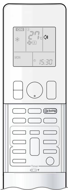
To start auto swing
Upper and lower airflow direction


" 念 " is displayed on the LCD.
- The flap (horizontal blade) will begin to swing.

To set the flap at desired position
- This function is effective while flap is in auto swing mode.


then the flap has reached the ion.
- “” disappears from the LCD.
To adjust the louvers at desired position
Hold the knob and move the louvers.
- You will find a knob on the left-side and the right-side blades.
- When the unit is installed in the corner of a room, the direction of the louvers (vertical blades) should be facing away from the wall.
If they face the wall, the wall will block off the wind, causing the cooling (or heating) efficiency to drop.
- If the flap is in the way, press _Swing on the remote controller to move the flap out of the way and then adjust the louvers.


Adjusting the Airflow Direction and Rate

To adjust the airflow rate setting

Each pressing of advances the airflow rate setting in sequence.

- When the airflow is set to "▲", indoor unit quiet operation will start and the noise from the unit will become quieter.
- In indoor unit quiet operation, the airflow rate is set to a weak level.
- In DRY or RADIANT operation, the airflow rate setting is not variable.
NOTE
Note on the angles of the flap
- The flap swinging range is the same by all operation. (See the figure.)

Note on airflow rate setting
- At smaller airflow rates, the cooling (heating) effect is also smaller.
CAUTION
- Always use a remote controller to adjust the angles of the flap. If you attempt to move it forcibly with hand when it is swinging, the mechanism may be broken.
- Be careful when adjusting the louvers.
Inside the air outlet, a fan is rotating at a high speed.
2.1.8 COMFORT AIRFLOW Operation

COMFORT AIRFLOW Operation

The flow of air will be in the upward direction while in COOL operation and in the downward direction while in HEAT operation, which will provide a comfortable wind that will not come in direct contact with people.
To start COMFORT AIRFLOW operation

- "A" is displayed on the LCD.
Airflow rate is set to Auto. COOL/DRY: The flap will go up.
HEAT: The flap will go down.
cancel COMFORT AIRFLOW operation

- The flaps will return to the memory position from before COMFORT AIRFLOW operation.
- " A " disappears from the LCD.

COOL operation

HEAT operation
NOTE
Notes on COMFORT AIRFLOW operation
- The flap position will change, preventing air from blowing directly on the occupants of the room.
- POWERFUL operation and COMFORT AIRFLOW operation cannot be used at the same time.
Priority is given to the function of whichever button is pressed last.
- The airflow rate will be set to Auto. If the upper and lower airflow direction is selected, the COMFORT AIRFLOW operation will be canceled.
2.1.9 INTELLIGENT EYE Operation

INTELLIGENT EYE Operation

"INTELLIGENT EYE" is the infrared sensor which detects the human movement. If nobody in the room for more than 20 minutes, the operation automatically changes to energy saving operation.
To start INTELLIGENT EYE operation

" is displayed on the LCD.
- The INTELLIGENT EYE lamp lights green.

Display
To cancel INTELLIGENT EYE operation

" disappears from the LCD.
- The INTELLIGENT EYE lamp goes off.

INTELLIGENT EYE Operation
[Example]
![DAIKIN FNA-A - [Example] - 1](/content/2020/11/206419/images/7ac11f6d627801862b2bb6f7c96791585910ac486ef251a662815e6d16498215.jpg)
When someone is in the room
Normal operation
The air conditioner is in normal operation while the sensor is detecting the movement of people.
When no one is in the room
20 minutes after, start energy saving operation.
The set temperature is shifted in ± 2^ steps.

Someone is back in the room
Back to normal operation.
The air conditioner will return to normal operation when the sensor detects the movement of people again.
INTELLIGENT EYE operation is useful for energy saving
Energy saving operation
- If no presence detected in the room for 20 minutes, the energy saving operation will start.
- This operation changes the temperature -2^ in HEAT / +2^ in COOL / +1^ in DRY operation from set temperature.
When the room temperature exceeds 30^ , the operation changes the temperature +1^ in COOL / +1^ in DRY operation from set temperature.
- This operation decreases the airflow rate slightly in FAN operation only.
NOTE
Notes on INTELLIGENT EYE operation
- Application range is as follows.

Vertical angle 90^ Horizontal angle 110^ (Side view) (Top view)

- Sensor may not detect moving objects further than 7m away. (Check the application range.)
- Sensor detection sensitivity changes according to indoor unit location, the speed of passersby, temperature range, etc.
The sensor also mistakenly detects pets, sunlight, fluttering curtains and light reflected off of mirrors as passersby.
- INTELLIGENT EYE operation will not go on during POWERFUL operation.
- NIGHT SET mode will not go on during use of INTELLIGENT EYE operation.
CAUTION
- Do not place large objects near the sensor.
Also keep heating units or humidifiers outside the sensor's detection area. This sensor can detect undesirable objects.
- Do not hit or violently push the INTELLIGENT EYE sensor. This can lead to damage and malfunction.
2.1.10 POWERFUL Operation
FTXG25/35/50JV1BW(A), FTXS20/25K2V1B, CTXS15/35K2V1B

POWERFUL Operation

POWERFUL operation quickly maximizes the cooling (heating) effect in any operation modes. You can get the maximum capacity.
To start POWERFUL operation
Press

during operation.
- POWERFUL operation ends in 20 minutes. Then the system automatically operates again with the previous settings which were used before POWERFUL operation.
- “ 喜 ” is displayed on the LCD.
To cancel POWERFUL operation
Press

again.
“” disappears from the LCD.

[Example]
■ Normal operation
- When you want to get the cooling effect quickly, start the POWERFUL operation.

■ POWERFUL operation
- POWERFUL operation will work for 20 minutes.

Back to normal operation
NOTE
Notes on POWERFUL operation
- When using POWERFUL operation, there are some functions which are not available.
- POWERFUL operation cannot be used together with ECONO, COMFORT AIRFLOW or OUTDOOR UNIT QUIET operation.
Priority is given to the function of whichever button is pressed last.
- POWERFUL operation can only be set when the unit is running. Pressing causes the settings to be canceled, and the disappears from the LCD.
- POWERFUL operation will not increase the capacity of the air conditioner if the air conditioner is already in operation with its maximum capacity demonstrated.
- In COOL and HEAT operation
To maximize the cooling (heating) effect, the capacity of outdoor unit is increased and the airflow rate is fixed to the maximum setting. The temperature and airflow settings are not variable.
In DRY operation
The temperature setting is lowered by 2.5^ and the airflow rate is slightly increased.
In FAN operation
The airflow rate is fixed to the maximum setting.
In AUTO operation
To maximize the cooling (heating) effect, the capacity of outdoor unit is increased and the airflow rate is fixed to the maximum setting.
FVXG25/35/50K2V1B

POWERFUL Operation

POWERFUL operation quickly maximises the cooling (heating) effect in any operation mode. You can get the maximum capacity.
To start POWERFUL operation
Press Powerful during operation.
- POWERFUL operation ends in 20 minutes. Then the system automatically operates again with the previous settings which were used before POWERFUL operation.
- " " is displayed on the LCD.
■To cancel POWERFUL operation
Press 4 again.
- " " disappears from the LCD.
[Example]
![DAIKIN FNA-A - [Example] - 1](/content/2020/11/206419/images/2ad0fa98c1b9bf024cdad59409c196ba6dfd0d1a83e9c52d6cebf177485db295.jpg)
■ Normal operation
- When you want to get the cooling effect quickly, start the POWERFUL operation.
![DAIKIN FNA-A - [Example] - 2](/content/2020/11/206419/images/4c3ca0277a7996eb22f14cd610013d546e8fe43655e68c21bcfd892537e9c642.jpg)
![DAIKIN FNA-A - [Example] - 3](/content/2020/11/206419/images/deccc6fc5ab86fb59684b596683bd6f727b4f17acc0ecab62e2040d5d91ad114.jpg)
■ POWERFUL operation
- POWERFUL operation will work for 20 minutes.
![DAIKIN FNA-A - [Example] - 4](/content/2020/11/206419/images/ed332185ff07e80b92ceba977b500d12e7c06e5a2ce889d0e50b71a53a9f363c.jpg)
![DAIKIN FNA-A - [Example] - 5](/content/2020/11/206419/images/870319a2c00be9848dc2f7262b11a60e7d5453b450cac878ed8d1f6b07a227bb.jpg)
Back to normal operation
NOTE
Notes on POWERFUL operation
- When using POWERFUL operation, there are some functions which are not available.
- POWERFUL operation cannot be used together with RADIANT2, ECONO or OUTDOOR UNIT QUIET operation.
Priority is given to the function of whichever button is pressed last.
- POWERFUL operation can only be set when the unit is running. Pressing ( GoOff ) causes the settings to be canceled,and the " " disappears from the LCD.
- POWERFUL operation will not increase the capacity of the air conditioner if the air conditioner is already in operation with its maximum capacity demonstrated.
- In COOL, HEAT and RADIANT1 operation
To maximise the cooling (heating) effect, the capacity of outdoor unit is increased and the airflow rate is fixed to the maximum setting. The temperature and airflow settings are not variable.
- In DRY operation
The temperature setting is lowered by 2.5^ and the airflow rate is slightly increased.
In FAN operation
The airflow rate is fixed to the maximum setting.
- In AUTO operation
To maximise the cooling (heating) effect, the capacity of outdoor unit is increased and the airflow rate is fixed to the maximum setting.
2.1.11 OUTDOOR UNIT QUIET Operation

OUTDOOR UNIT QUIET Operation

OUTDOOR UNIT QUIET operation lowers the noise level of the outdoor unit by changing the frequency and fan speed on the outdoor unit. This function is convenient during the night.
To start OUTDOOR UNIT QUIET operation

- “ 12 ” is displayed on the LCD.
To cancel OUTDOOR UNIT QUIET operation

- " " disappears from the LCD.
[Example] Using the OUTDOOR UNIT QUIET operation during the night.

- The noise level of the outdoor unit will be lower. This is convenient when you need to consider for your neighbourhood.
NOTE
Notes on OUTDOOR UNIT QUIET operation
- This function is available in COOL, HEAT, and AUTO operation.
This is not available in RADIANT, FAN and DRY operation.
- POWERFUL operation and OUTDOOR UNIT QUIET operation cannot be used at the same time.
Priority is given to the function of whichever button is pressed last.
Even the operation is stopped using the remote controller or the indoor unit ON/OFF switch when using OUTDOOR UNIT QUIET operation,
"16" will remain on the remote controller display.
- OUTDOOR UNIT QUIET operation will drop neither the frequency nor fan speed if they have been already dropped low enough.
2.1.12 ECONO Operation

ECONO Operation

ECONO operation is a function which enables efficient operation by limiting the maximum power consumption value.
This function is useful for cases in which attention should be paid to ensure a circuit breaker will not trip when the product runs alongside other appliances.
To start ECONO operation
Press E cono during operation.
- " " is displayed on the LCD.
To cancel ECONO operation
Press Econo again.
“”disappears from the LCD.
[Example]
![DAIKIN FNA-A - [Example] - 1](/content/2020/11/206419/images/7f3c7a96c340144ea13e55aaf2a860588662a90f9c75271c277876c6c884402b.jpg)
Normal operation
![DAIKIN FNA-A - [Example] - 2](/content/2020/11/206419/images/7c09ec5611de9daa8900ae12f7bcb46eb31f598c4f1480aa2b43d06146c9f6b9.jpg)
ECONO operation
-
In case the air conditioner and other appliances which require high power consumption are used at same time, a circuit breaker may trip if the air conditioner operates with its maximum capacity.
-
The maximum power consumption of the air conditioner is limited by using ECONO operation.
The circuit breaker will hardly trip even if the air conditioner and other appliances are used at same time.
![DAIKIN FNA-A - [Example] - 3](/content/2020/11/206419/images/f8f4d9a739b2e6930ad7981188871d87dd142761fc223072088483483f2ec438.jpg)
- This diagram is a representation for illustrative purposes only.
The maximum running current and power consumption of the air conditioner in ECONO operation vary with the connecting outdoor unit.
NOTE
Notes on ECONO operation
- ECONO operation can only be set when the unit is running. Pressing causes the settings to be canceled, and the " " disappears from the LCD.
- ECONO operation is a function which enables efficient operation by limiting the power consumption of the outdoor unit (operating frequency).
- ECONO operation functions in AUTO, COOL, DRY, and HEAT operation.
This is not available in RADIANT and FAN operation.
- POWERFUL operation and ECONO operation cannot be used at the same time.
Priority is given to the function of whichever button is pressed last.
- If the level of power consumption is already low, ECONO operation will not drop the power consumption.
2.1.13 OFF TIMER Operation
FTXG25/35/50JV1BW(A)

OFF TIMER Operation

Timer functions are useful for automatically switching the air conditioner on or off at night or in the morning. You can also use OFF TIMER and ON TIMER in combination.
To use OFF TIMER operation
- Check that the clock is correct. If not, set the clock to the present time.
1. Press Off

"000" is displayed on the LCD.
"OFF" blinks.
- “ ” and day of the week disappear from the LCD.
2. Press Select until the time setting reaches the point you like.
- Each pressing of either button increases or decreases the time setting by 10 minutes. Holding down either button changes the time setting rapidly.
3. Press Off again.
- " OFF " and setting time are displayed on the LCD.
- The multi-monitor lamp blinks twice.
The TIMER lamp periodically lights orange.

Display
To cancel OFF TIMER operation
Press
Cancel

- "OFF" and setting time disappear from the LCD.
- “ ” and day of the week are displayed on the LCD.
NOTE
Notes on TIMER operation
- When TIMER is set, the present time is not displayed.
- Once you set ON/OFF TIMER, the time setting is kept in the memory. The memory is canceled when remote controller batteries are replaced.
- When operating the unit via the ON/OFF TIMER, the actual length of operation may vary from the time entered by the user. (Maximum approx. 10 minutes)
NIGHT SET mode
- When the OFF TIMER is set, the air conditioner automatically adjusts the temperature setting (0.5°C up in COOL, 2.0°C down in HEAT) to prevent excessive cooling (heating) for your pleasant sleep.
FTXS20/25K2V1B, CTXS15/35K2V1B

OFF TIMER Operation

Timer functions are useful for automatically switching the air conditioner on or off at night or in the morning. You can also use OFF TIMER and ON TIMER in combination.
To use OFF TIMER operation
- Check that the clock is correct.
If not, set the clock to the present time.
1. Press Off

"000" is displayed on the LCD.
"OFF" blinks.
- “ ” and day of the week disappear from the LCD.
2. Press Select point you
until the time setting reaches the like.
Each pressing of either button increases or decreases the time setting by 10 minutes.
Holding down either button changes the time setting rapidly.
3. Press again.
- "OFF" and setting time are displayed on the LCD.
- The TIMER lamp lights yellow.

Display
To cancel OFF TIMER operation
Press
Cancel
"OFF" and setting time disappear from the LCD.
- “ ” and day of the week are displayed on the LCD.
- The TIMER lamp goes off.
NOTE
Notes on TIMER operation
- When TIMER is set, the present time is not displayed.
- Once you set ON/OFF TIMER, the time setting is kept in the memory. The memory is canceled when remote controller batteries are replaced.
- When operating the unit via the ON/OFF TIMER, the actual length of operation may vary from the time entered by the user. (Maximum approx. 10 minutes)
NIGHT SET mode
- When the OFF TIMER is set, the air conditioner automatically adjusts the temperature setting (0.5°C up in COOL, 2.0°C down in HEAT) to
prevent excessive cooling (heating) for your pleasant sleep.
FVXG25/35/50K2V1B

OFF TIMER Operation

Timer functions are useful for automatically switching the air conditioner on or off at night or in the morning. You can also use OFF TIMER and ON TIMER in combination.
To use OFF TIMER operation

"000" is displayed on the LCD.
-
"OFF" blinks.
-
“ ” and day of the week disappear from the LCD.
-
Press Select until the time setting reaches the point you like.
-
Each pressing of either button increases or decreases the time setting by 10 minutes. Holding down either button changes the time setting rapidly.
-
Press Off again.
-
"OFF" and setting time are displayed on the LCD.
- The OPERATION lamp blinks and the TIMER lamp lights yellow.

Display
■To cancel OFF TIMER operation

- "OFF" and setting time disappear from the LCD.
- “ ” and day of the week are displayed on the LCD.
NOTE
Notes on TIMER operation
- When TIMER is set, the present time is not displayed.
- Once you set ON/OFF TIMER, the time setting is kept in the memory. The memory is canceled when remote controller batteries are replaced.
- When operating the unit via the ON/OFF TIMER, the actual length of operation may vary from the time entered by the user. (Maximum approximately 10 minutes)
NIGHT SET mode
- When the OFF TIMER is set, the air conditioner automatically adjusts the temperature setting (0.5°C up in COOL, 2.0°C down in HEAT) to prevent excessive cooling (heating) for your pleasant sleep.
2.1.14 ON TIMER Operation
FTXG25/35/50JV1BW(A)

ON TIMER Operation

To use ON TIMER operation
- Check that the clock is correct.
If not, set the clock to the present time.
1. Press On
- “ 6:00 ” is displayed on the LCD.
"ON" blinks.
- “ ” and day of the week disappear from the LCD.
2. Press Select until the time setting reaches the point you like.
Each pressing of either button increases or decreases the time setting by 10 minutes.
Holding down either button changes the setting rapidly.
3. Press on again.
- "ON" and setting time are displayed on the LCD.
- The multi-monitor lamp blinks twice.
The TIMER lamp periodically lights orange.

Display
To cancel ON TIMER operation
PressCancel
"ON" and setting time disappear from the LCD.
- “ ” and day of the week are displayed on the LCD.
To combine ON TIMER and OFF TIMER
- A sample setting for combining the 2 timers is shown below.
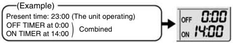
NOTE
In the following cases, set the timer again.
After a breaker has turned off.
After a power failure.
- After replacing batteries in the remote controller.
FTXS20/25K2V1B, CTXS15/35K2V1B

ON TIMER Operation

To use ON TIMER operation
- Check that the clock is correct.
If not, set the clock to the present time.
1. Press On

2. Press Select until the time setting reaches the point you like.
- Each pressing of either button increases or decreases the time setting by 10 minutes. Holding down either button changes the setting rapidly.
3. Press on again.
"ON" and setting time are displayed on the LCD.
- The TIMER lamp lights yellow.

Display
To cancel ON TIMER operation
PressCancel
- "ON" and setting time disappear from the LCD.
- “ ” and day of the week are displayed on the LCD.
- The TIMER lamp goes off.
To combine ON TIMER and OFF TIMER
- A sample setting for combining the 2 timers is shown below.
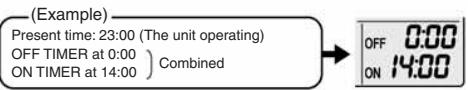
NOTE
In the following cases, set the timer again.
After a breaker has turned off.
After a power failure.
- After replacing batteries in the remote controller.
FVXG25/35/50K2V1B

ON TIMER Operation

■To use ON TIMER operation
- Check that the clock is correct.
If not, set the clock to the present time.
1. Press On

2. Press Select until the time setting reaches the point you like.
- Each pressing of either button increases or decreases the time setting by 10 minutes. Holding down either button changes the time setting rapidly.
3. Press On again.
- "ON" and setting time are displayed on the LCD.
- The OPERATION lamp blinks and the TIMER lamp lights yellow.

To cancel ON TIMER operation
Press cancel
"ON" and setting time disappear from the LCD.
- “ ” and day of the week are displayed on the LCD.
To combine ON TIMER and OFF TIMER
- A sample setting for combining the 2 timers is shown below.

NOTE
In the following cases, set the timer again.
After a breaker has turned off.
After a power failure.
After replacing batteries in the remote controller.
2.1.15 WEEKLY TIMER Operation

WEEKLY TIMER Operation
Up to 4 timer settings can be saved for each day of the week. It is convenient if the WEEKLY TIMER is set according to the family's life style.
Using in these cases of WEEKLY TIMER
[Example] The same timer settings are made for the week from Monday through Friday while different timer settings are made for the weekend.
| [Monday] | Make timer settings up to programs 1-4. |
| Program 1
ON
25°C
6:00 | Program 2
OFF
8:30 | Program 3
ON
27°C
17:30 | Program 4
OFF
22:00 |
| [Tuesday]
to
[Friday] | Use the copy mode to make settings for Tuesday to Friday, because these settings are the same as those for Monday.
Program 1
ON
25°C
6:00 | Program 2
OFF
17:30 | Program 3
ON
27°C
17:30 | Program 4
OFF
22:00 |
| [Saturday] | No timer settings |
| [Sunday] | Make timer settings up to programs 1-4. |
| Program 1
ON
25°C
8:00 | Program 2
OFF
10:00 | Program 3
ON
27°C
19:00 | Program 4
OFF
21:00 |
| | | | | | | | |
- Up to 4 reservations per day and 28 reservations per week can be set in the WEEKLY TIMER. The effective use of the copy mode ensures ease of making reservations.
- The use of ON-ON-ON-ON settings, for example, makes it possible to schedule operating mode and set temperature changes. Furthermore, by using OFF-OFF-OFF-OFF settings, only the turn off time of each day can be set. This will turn off the air conditioner automatically if the user forgets to turn it off.

To use WEEKLY TIMER operation
Setting mode
- Make sure the day of the week and time are set. If not, set the day of the week and time.

Setting Displays

1. Press 念
- The day of the week and the reservation number of the current day will be displayed.
- 1 to 4 settings can be made per day
2. Press Select to select the desired day of the week and reservation number.
- Pressing changes the reservation number and the day of the week.
3. Press Next
- The day of the week and reservation number will be set.
" WEEKLY " and " ON " blink.
4. Press Select to select the desired mode.
- Pressing changes "ON" or "OFF" setting in sequence.
Pressing alternates the following items appearing on the LCD in rotational sequence.

- In case the reservation has already been set, selecting "blank" deletes the reservation.
- Go to step 9 if "blank" is selected.
- To return to the day of the week and reservation number setting, press Back.
5. Press Next
- The ON/OFF TIMER mode will be set.
- " WEEKLY" and the time blink.

WEEKLY TIMER Operation

6. Press
to select the desired time.
The time can be set between 0:00 and 23:50 in 10 minute intervals.
- To return to the ON/OFF TIMER mode setting, press Back.
- Go to step 9 when setting the OFF TIMER.
7. Press
Next

The time will be set.
WEEKLY and the temperature blink.
8. Press

he can be set between 10^ and 32^ .
COOL or AUTO: The unit operates at 18^ even if it is set at 10 to 17^ .
HEAT or AUTO: The unit operates at 30^ even if it is set at 31 to 32^ .
- To return to the time setting, press Back
- The set temperature is only displayed when the mode setting is on.
9. Press
Next

- Be sure to direct the remote controller toward the indoor unit and check for a receiving tone and flashing the OPERATION lamp.
- The temperature is set while in ON TIMER operation, and the time is set while in OFF TIMER operation.
- The next reservation screen will appear.
- To continue further settings, repeat the procedure from step 4.
- The TIMER lamp lights yellow.

Display
10. Press

to complete the setting.
- “ WEEKLY” is displayed on the LCD and WEEKLY TIMER operation is activated.
- A reservation made once can be easily copied and the same settings used for another day of the week. Refer to copy mode.
NOTE
Notes on WEEKLY TIMER operation
- Do not forget to set the clock on the remote controller first.
- The day of the week, ON/OFF TIMER mode, time and set temperature (only for ON TIMER mode) can be set with WEEKLY TIMER. Other settings for ON TIMER are based on the settings just before the operation.
- Both WEEKLY TIMER and ON/OFF TIMER operation cannot be used at the same time. The ON/OFF TIMER operation has priority if it is set while WEEKLY TIMER is still active. The WEEKLY TIMER will go into standby state, and "ON/OFF TIMER" will disappear from the LCD. When ON/OFF TIMER is up, the WEEKLY TIMER will automatically become active.
- Shutting the breaker off, power failure, and other similar events will render operation of the indoor unit's internal clock inaccurate. Reset the clock.

Copy mode
- A reservation made once can be copied to another day of the week. The whole reservation of the selected day of the week will be copied.

Setting Displays

Confirmation


Paste


Normal
- Press
- Press Select to confirm the day of the week to be copied.
-
Press Copy
-
The whole reservation of the selected day of the week will be copied.
- Press Select to select the destination day of the week.
-
Press Copy
-
Be sure to direct the remote controller toward the indoor unit and check for a receiving tone and flashing the OPERATION lamp.
- The reservation will be copied to the selected day of the week. The whole reservation of the selected day of the week will be copied.
-
To continue copying the settings to other days of the week, repeat step 4 and step 5.
-
Press to complete the setting.
-
“ WEEKLY” is displayed on the LCD and WEEKLY TIMER operation is activated.
NOTE
Note on copy mode
- The entire reservation of the source day of the week is copied in the copy mode.
In the case of making a reservation change for any day of the week individually after copying the content of weekly reservations, press and change the settings in the steps of setting mode.

WEEKLY TIMER Operation

Confirming a reservation
The reservation can be confirmed.

-
Press
-
The day of the week and the reservation number of the current day will be displayed.
-
Press Select to select the day of the week and the reservation number to be confirmed.
-
Pressing Select displays the reservation details.
- To change the confirmed reserved settings, select the reservation number and press Next
The mode is switched to setting mode. Go to setting mode step 2.
- Press to exit confirming mode.
To deactivate WEEKLY TIMER operation
Press Weekly while " WEEKLY" is displayed on the LCD.
The " WEEKLY" will disappear from the LCD.
- The TIMER lamp goes off.
- To reactivate the WEEKLY TIMER operation, press weekly again.
- If a reservation deactivated with is activated once again, the last reservation mode will be used.

CAUTION
- If not all the reservation settings are reflected, deactivate the WEEKLY TIMER operation once. Then press again to reactivate the WEEKLY TIMER operation.

To delete reservations
The individual reservation
-
Press
-
The day of the week and the reservation number will be displayed.
-
Press Select to select the day of the week and the reservation number to be deleted.
-
Press Next
-
“ WEEKLY” and “ON” or “OFF” blink.
-
Press Select and select "blank".
-
Pressing changes ON/OFF TIMER mode.
Pressing alternates the following items appearing on the LCD in rotational sequence.
- The reservation will be no setting with selecting "blank".

-
Press Next
-
The selected reservation will be deleted.
-
Press
-
If there are still other reservations, WEEKLY TIMER operation will be activated.
The reservations for each day of the week
- This function can be used for deleting reservations for each day of the week.
-
It can be used while confirming or setting reservations.
-
Press Select to select the day of the week to be deleted.
-
Hold Weekly for 5 seconds.
-
The reservation of the selected day of the week will be deleted.
All reservations
Weekly
Hold for 5 seconds while normal display.
- Be sure to direct the remote controller toward the indoor unit and check for a receiving tone.
- This operation is not effective while WEEKLY TIMER is being set.
- All reservations will be deleted.
2.1.16 Note for Multi System
Note for Multi System
Multi system has one outdoor unit connected to multiple indoor units.
Selecting the operation mode
With the priority room setting present but inactive or not present.
When more than one indoor unit is operating, priority is given to the first unit that was turned on. In this case, set the units that are turned on later to the same operation mode as the first unit.
Otherwise, they will enter the standby state, and the OPERATION lamp will flash: this does not indicate malfunction.

Outdoor unit
NOTE
Notes on operation mode for multi system
- COOL, DRY and FAN operation may be used at the same time.
- HEAT and RADIANT operation may be used at the same time.
- AUTO operation automatically selects COOL operation or HEAT operation based on the room temperature.
Therefore, AUTO operation is available when selecting the same operation mode as that of the room with the first unit to be turned on.
CAUTION
- Normally, the operation mode in the room where the unit is first run is given priority, but the following situations are exceptions, so please keep this in mind.
If the operation mode of the first room is FAN operation, then using HEAT and RADIANT operation in any room after this will give priority to HEAT and RADIANT operation. In this situation, the air conditioner running in FAN operation will go on standby, and the OPERATION lamp will flash.
When the RADIANT operation starts when the FAN operation is used in another room, the FAN operation is switched to the HEAT operation.
With the priority room setting active.
Refer to priority room setting on the next page.
NIGHT QUIET mode (Available only for COOL operation)
NIGHT QUIET mode requires initial programming during installation. Please consult your retailer or dealer for assistance. NIGHT QUIET mode reduces the operation noise of the outdoor unit during the nighttime hours to prevent annoyance to neighbours.
- The NIGHT QUIET mode is activated when the temperature drops 5^ or more below the highest temperature recorded that day. Therefore, when the temperature difference is less than 5^ , this function will not be activated.
- NIGHT QUIET mode reduces slightly the cooling efficiency of the unit.
OUTDOOR UNIT QUIET operation
Refer to OUTDOOR UNIT QUIET operation.
With the priority room setting present but inactive or not present.
When using the OUTDOOR UNIT QUIET operation feature with the multi system, set all indoor units to OUTDOOR UNIT QUIET operation using their remote controllers.
When clearing OUTDOOR UNIT QUIET operation, clear one of the operating indoor units using their remote controller. However OUTDOOR UNIT QUIET operation display remains on the remote controller for other rooms.
We recommend you release all rooms using their remote controllers.
With the priority room setting active.
Refer to priority room setting on the next page.
COOL/HEAT mode lock
The COOL/HEAT mode lock requires initial programming during installation. Please consult your authorised dealer for assistance. The COOL/HEAT mode lock sets the unit forcibly to either COOL or HEAT operation. This function is convenient when you wish to set all indoor units connected to the multi system to the same operation mode. During the COOL mode, the DRY operation can also be used. During the HEAT mode, the RADIANT operation can also be used.
NOTE
- The COOL/HEAT mode lock cannot be activated together with the priority room setting.
Priority room setting
The priority room setting requires initial programming during installation. Please consult your authorised dealer for assistance.
The room designated as the priority room takes priority in the following situations.
Operation mode priority
- As the operation mode of the priority room takes precedence, the user can select a different operation mode from other rooms.
[Example]
- Room A is the priority room in the examples.
When COOL operation is selected in room A while operating the following modes in room B, C and D:
| Operation mode in room B, C and D | Status of room B, C and D when the unit in room A is in COOL operation |
| COOL or DRY or FAN | Current operation mode maintained |
| HEAT and RADIANT | The unit enters standby mode. Operation resumes when the room A unit stops operating. |
| AUTO | If the unit is set to COOL operation, it continues. If the unit is set to HEAT operation, it enters standby mode. Operation resumes when the room A unit stops operating. |
Priority when POWERFUL operation is used
[Example]
- Room A is the priority room in the examples. The indoor units in rooms A, B, C and D are all operating. If the unit in room A enters POWERFUL operation, operation capacity will be concentrated in room A. In such a case, the cooling (heating) efficiency of the units in room B, C and D may be slightly reduced.
Priority when using OUTDOOR UNIT QUIET operation
[Example]
- Room A is the priority room in the examples. Just by setting the unit in room A to QUIET operation, the air conditioner starts OUTDOOR UNIT QUIET operation. You don't have to set all the operated indoor units to QUIET operation.
2.1.17 Quick Reference
FTXG25/35/50JV1BW(A)

Quick Reference
FTXS20/25K2V1B, CTXS15/35K2V1B

Quick Reference
FVXG25/35/50K2V1B

Quick Reference

2.2 FTXS-J, FTXS-G, FVXS Series - ARC452A1, A3
2.2.1 Manual Contents and Reference Page
| Model Series | Wall Mounted Type | Floor Standing Type |
| FTXS25-50J2V1B | FTXS60/71GV1B | FVXS25-50FV1B |
| Read Before Operation | | | |
| Names of Parts | 179 | 182 | 185 |
| Operation | | | |
| AUTO · DRY · COOL · HEAT · FAN
Operation ★ | 188 | 188 | 188 |
| Adjusting the Airflow Direction | 190 | 192 | 194 |
| COMFORT AIRFLOW and INTELLIGENT
EYE Operation | 196 | 200 | — |
| POWERFUL Operation ★ | 203 | 203 | 203 |
| OUTDOOR UNIT QUIET Operation ★ | 204 | 204 | 204 |
| ECONO Operation ★ | 205 | 205 | 205 |
| OFF TIMER Operation ★ | 206 | 206 | 206 |
| ON TIMER Operation ★ | 207 | 207 | 207 |
| WEEKLY TIMER Operation ★ | 208 | 208 | 208 |
| Note for Multi System ★ | 216 | 216 | 216 |
| Drawing No. | 3P266959-2A | 3P248442-3 | 3P191290-1K |
: The illustrations are for FTXS-J series as representative.
2.2.2 Names of Parts
FTXS20/25/35/42/50J2V1B
Names of Parts
Indoor Unit
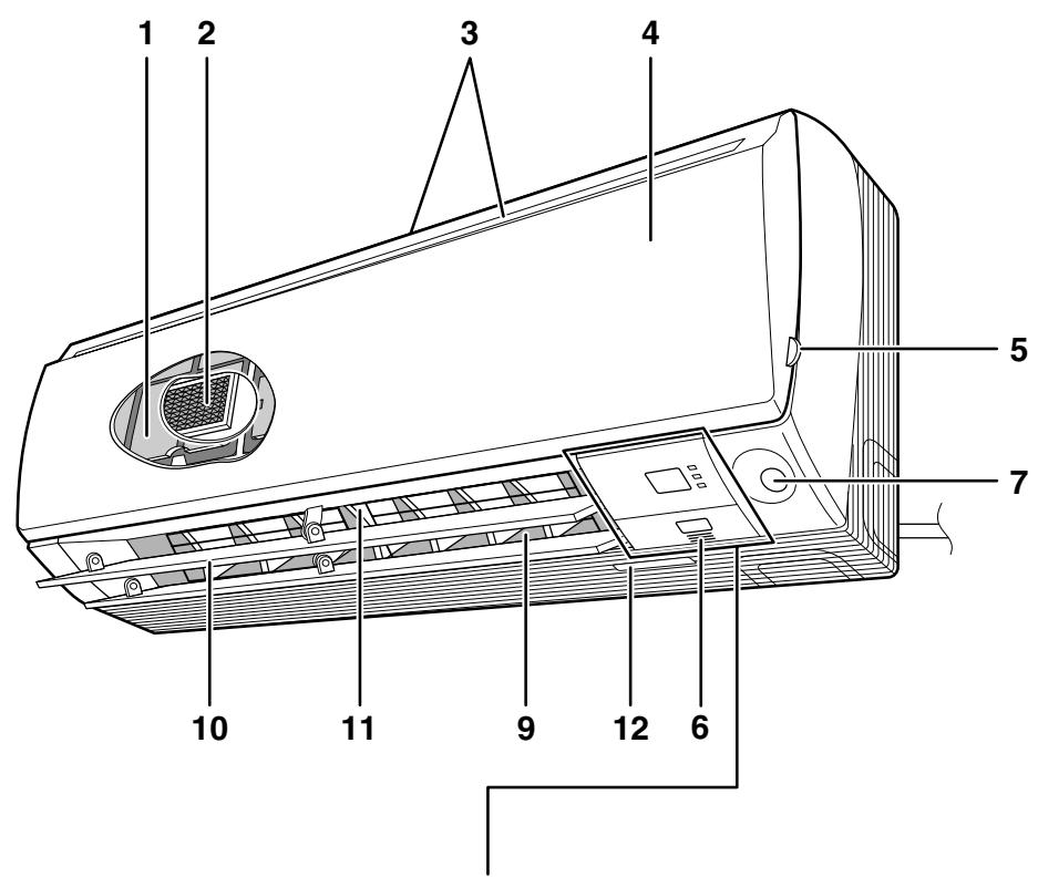

Indoor Unit
1. Air filter
3. Air inlet
- Titanium apatite photocatalytic air-purifying filter:
These filters are attached to the inside of the air filters.
- Front panel
- Panel tab
- Room temperature sensor:
- It senses the air temperature around the unit.
- INTELLIGENT EYE sensor
- Display
- Air outlet
- Flaps (horizontal blades)
- Louvers (vertical blades):
- The louvers are inside of the air outlet.
- Model name plate
13. Indoor unit ON/OFF switch:
- Push this switch once to start operation.
Push once again to stop it.
- The operation mode refers to the following table.
| Model | Mode | Temperature setting | Airflow rate |
| COOLING ONLY | COOL | 22°C | AUTO |
| HEAT PUMP | AUTO | 25°C | AUTO |
- This switch is useful when the remote controller is missing.
14. OPERATION lamp (green)
-
TIMER lamp (yellow)
-
INTELLIGENT EYE lamp (green)
-
Signal receiver:
-
It receives signals from the remote controller.
- When the unit receives a signal, you will hear a beep sound.
Operation start .beep-beep
- Settings changed......beep
Operation stop.....long beep
Remote Controller

-
Signal transmitter:
-
It sends signals to the indoor unit.
-
Display:
-
It displays the current settings. (In this illustration, each section is shown with its displays ON for the purpose of explanation.)
-
FAN setting button:
-
It selects the airflow rate setting.
-
POWERFUL button:
POWERFUL operation
-
ON/OFF button:
-
Press this button once to start operation. Press once again to stop it.
-
TEMPERATURE adjustment buttons:
-
It changes the temperature setting.
-
MODE selector button:
-
It selects the operation mode. (AUTO/DRY/COOL/HEAT/FAN)
-
QUIET button:
OUTDOOR UNIT QUIET operation
- ECONO button:
ECONO operation
- SWING button:
Horizontal blades (flaps)


- SWING button:
Vertical blades (louvers)
12.COMFORT/SENSOR button:
COMFORT AIRFLOW and INTELLIGENT EYE operation
- WEEKLY/PROGRAM/COPY/BACK/NEXT button:
- WEEKLY TIMER operation
- SELECT button:
- It changes the ON/OFF TIMER and WEEKLY TIMER settings.
- OFF TIMER button
- ON TIMER button
- TIMER CANCEL button:
- It cancels the timer setting.
- It cannot be used for the WEEKLY TIMER operation.
- CLOCK button
FTXS60/71GV1B
Names of Parts
Indoor Unit

Indoor Unit
- Air filter
- Titanium apatite photocatalytic air-purifying filter:
These filters are attached to the inside of the air filters.
- Air inlet
-
Front panel
-
Panel tab
-
Room temperature sensor:
It senses the air temperature around the unit.
- INTELLIGENT EYE sensor
- Display
-
Air outlet
-
Flaps (horizontal blades)
-
Louvers (vertical blades):
- The louvers are inside of the air outlet.
-
Model name plate
-
Indoor unit ON/OFF switch:
-
Push this switch once to start operation.
Push once again to stop it.
- The operation mode refers to the following table.
| Model | Mode | Temperature setting | Airflow rate |
| COOLING ONLY | COOL | 22°C | AUTO |
| HEAT PUMP | AUTO | 25°C | AUTO |
-
This switch is useful when the remote controller is missing.
-
OPERATION lamp (green)
-
TIMER lamp (yellow)
-
INTELLIGENT EYE lamp (green)
-
Signal receiver:
-
It receives signals from the remote controller.
- When the unit receives a signal, you will hear a beep sound.
Operation start .beep-beep
- Settings changed......beep
Operation stop.....long beep
Names of Parts

Remote Controller
- Signal transmitter:
- It sends signals to the indoor unit.
- Display (LCD):
It displays the current settings.
(In this illustration, each section is shown with its displays on for the purpose of explanation.)
-
FAN setting button:
-
It selects the airflow rate setting.
-
POWERFUL button:
POWERFUL operation
-
ON/OFF button:
-
Press this button once to start operation. Press once again to stop it.
-
TEMPERATURE adjustment buttons:
-
It changes the temperature setting.
-
MODE selector button:
-
It selects the operation mode. (AUTO/DRY/COOL/HEAT/FAN)
-
QUIET button:
OUTDOOR UNIT QUIET operation
- ECONO button:
ECONO operation


- SWING button:
Flaps (horizontal blades)
-
SWING button:
-
Louvers (vertical blades)
12.COMFORT/SENSOR button:
COMFORT AIRFLOW and INTELLIGENT EYE operation
-
WEEKLY/PROGRAM/COPY/BACK/NEXT button:
-
WEEKLY TIMER operation
-
SELECT button:
-
It changes the ON/OFF TIMER and WEEKLY TIMER settings.
-
OFF TIMER button
-
ON TIMER button
-
TIMER CANCEL button:
-
It cancels the timer setting.
-
It cannot be used for the WEEKLY TIMER operation.
-
CLOCK button
FVXS25/35/50FV1B
Names of parts
Indoor Unit


Opening the Front Panel
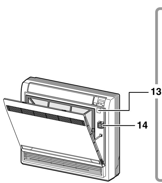

CAUTION
Before opening the front panel, be sure to stop the operation and turn the breaker OFF. Do not touch the metal parts on the inside of the indoor unit, as it may result in injury.
Indoor Unit
1. Titanium Apatite Photocatalytic Air-Purifying Filter:
These filters are attached to the inside of the air filters.
-
Air outlet
-
Display
-
Front panel
-
Vertical blades (louvers)
-
The louvers are inside of the air outlet.
-
Air inlet
-
Air filter
-
Horizontal blade (flap)
-
Operation lamp (green)
-
TIMER lamp (yellow)
-
Indoor Unit ON/OFF switch:
-
Push this switch once to start operation.
Push once again to stop it.
-
The operation mode refers to the following table.
| Model | Mode | Temperature setting | Airflow rate |
| COOLING ONLY | COOL | 22°C | AUTO |
| HEAT PUMP | AUTO | 25°C | AUTO |
- This switch is useful when the remote controller is missing.
12. Signal receiver:
-
It receives signals from the remote controller.
-
When the unit receives a signal, you will hear a short beep.
Operation start .beep-beep
- Settings changed ....beep
Operation stop... beeeeeep
Air outlet selection switch
-
Room temperature sensor:
-
It senses the air temperature around the unit.
Remote Controller

-
Signal transmitter:
-
It sends signals to the indoor unit.
-
Display:
-
It displays the current settings.
(In this illustration, each section is shown with all its displays ON for the purpose of explanation.)
-
FAN setting button:
-
It selects the airflow rate setting.
-
POWERFUL button:
POWERFUL operation
-
ON/OFF button:
-
Press this button once to start operation. Press once again to stop it.
-
TEMPERATURE adjustment buttons:
-
It changes the temperature setting.
-
MODE selector button:
It selects the operation mode.
(AUTO/DRY/COOL/HEAT/FAN)
- QUIET button:
OUTDOOR UNIT QUIET operation


- ECONO button:
ECONO operation
-
SWING button:
-
Adjusting the Airflow Direction
-
WEEKLY/PROGRAM/COPY/BACK/NEXT button:
WEEKLY TIMER operation
-
SELECT button:
-
It changes the ON/OFF TIMER and
EKLY TIMER settings.
-
OFF TIMER button
-
ON TIMER button
-
TIMER CANCEL button:
-
It cancels the timer setting.
-
It cannot be used for the WEEKLY TIMER operation.
-
CLOCK button
2.2.3 AUTO · DRY · COOL · HEAT · FAN Operation
AUTO · DRY · COOL · HEAT · FAN Operation
The air conditioner operates with the operation mode of your choice.
From the next time on, the air conditioner will operate with the same operation mode.
To start operation
1. Press MODE and select a operation mode.
Each pressing of the button advances the mode setting in sequence.
A: AUTO


COOL

COOLING ONLY model

HEAT PUMP model
- "ON" is displayed on the LCD.
- The OPERATION lamp lights up.


To stop operation
ON/OFF
3. Press again.
- "ON" disappears from the LCD.
- Then OPERATION lamp goes off.
To change the temperature setting
4. Press


| AUTO or COOL or HEAT operation | DRY or FAN operation |
| Press ▲ raise the temperature and press ▼ lower the temperature. | The temperature setting is not variable. |
| Set to the temperature you like. | ①27℃ |
To change the airflow rate setting
5. Press
| AUTO or COOL or HEAT or FAN operation | DRY operation |
| 5 levels of airflow rate setting from “-” to “■” plus “▲” “▲”are available. | The airflow rate setting is not variable. |
- Indoor unit quiet operation
When the airflow is set to “ ”, the noise from the indoor unit will become quieter.
Use this when making the noise quieter.
NOTE
Notes on HEAT operation
- Since this air conditioner heats the room by taking heat from outdoor air to indoors, the heating capacity becomes smaller in lower outdoor temperatures. If the heating effect is insufficient, it is recommended to use another heating appliance in combination with the air conditioner.
- The heat pump system heats the room by circulating hot air around all parts of the room. After the start of heating operation, it takes some time before the room gets warmer.
- In heating operation, frost may occur on the outdoor unit and lower the heating capacity. In that case, the system switches into defrosting operation to take away the frost.
- During defrosting operation, hot air does not flow out of indoor unit.
- A pinging sound may be heard during defrosting operation, which, however does not mean that the air conditioner has failures.
Note on COOL operation
- This air conditioner cools the room by releasing the heat in the room outside.
Therefore, the cooling performance of the air conditioner may be degraded if the outdoor temperature is high.
Note on DRY operation
- The computer chip works to rid the room of humidity while maintaining the temperature as much as possible. It automatically controls temperature and airflow rate, so manual adjustment of these functions is unavailable.
Notes on AUTO operation
- In AUTO operation, the system selects an appropriate operation mode (COOL or HEAT) based on the room and outside temperatures and starts the operation.
- The system automatically reselects setting at a regular interval to bring the room temperature to user-setting level.
Note on FAN operation
- This mode is valid for fan only.
Note on airflow rate setting
- At smaller airflow rates, the cooling (heating) effect is also smaller.
2.2.4 Adjusting the Airflow Direction
FTXS20/25/35/42/50J2V1B
Adjusting the Airflow Direction
You can adjust the airflow direction to increase your comfort.
To start auto swing
Upper and lower airflow direction
Press
- “” is displayed on the LCD.
- The flaps (horizontal blades) will begin to swing.
Right and left airflow direction
Press
- “ 空 ” is displayed on the LCD.
- The louvers (vertical blades) will begin to swing.
The 3-D airflow direction
Press and
“”and“”are displayed on the LCD.
- The flaps and louvers move in turn.
- To cancel 3-D airflow, press either or again.
The flaps or louvers will stop moving.

- The following illustrations show respective airflow directions.


To set the flaps or louvers at desired position
- This function is effective while flaps or louvers are in auto swing mode.
Press and when the flaps or louvers have reached the desired position.
- In the 3-D airflow, the flaps and louvers move in turn.
- “” or “” disappears from the LCD.

CAUTION
- Always use a remote controller to adjust the angles of the flaps and louvers. If you attempt to move the flaps and louvers forcibly with hand when they are swinging, the mechanism may be broken.
- Always use a remote controller to adjust the louvers angles. In side the air outlet, a fan is rotating at a high speed.
NOTE
Note on the angles of the flaps
- The flaps swinging range depends on the operation. (See the figure.)
Note on 3-D airflow
- Using 3-D airflow circulates cold air, which tends to be collected at the bottom of the room, and hot air, which tends to collect near the ceiling, throughout the room, preventing are as of cold and hot developing.

FTXS60/71GV1B
Adjusting the Airflow Direction
You can adjust the airflow direction to increase your comfort.
To start auto swing
Upper and lower airflow direction
Press

- " 喜 " is displayed on the LCD.
- The flaps (horizontal blades) will begin to swing.
Right and left airflow direction

- “” is displayed on the LCD.
- The louvers (vertical blades) will begin to swing.
The 3-D airflow direction


- “” and ““” are displayed on the LCD.
- The flaps and louveres move in turn.
- To cancel 3-D airflow, press either or again.
The flaps or louvers will stop moving.

- The following illustrations show respective airflow directions.

Upper/Lower

Right/Left

3-D
To set the flaps or louvers at desired position
- This function is effective while flaps or louver are in auto swing mode.
Press and when the flaps or louvers have reached the desired position.
- In the 3-D airflow, the flaps and louvers move in turn.
- “” or “” disappears from the LCD.
CAUTION
- Always use a remote controller to adjust the angles of the flaps and louvers. If you attempt to move it forcibly with hand when it is swinging, the mechanism may be broken.
- Always use a remote controller to adjust the louvers angles. In side the air outlet, a fan is rotating at a high speed.
NOTE
Note on the angles of the flaps
- The flaps swinging range depends on the operation. (See the figure.)
Note on 3-D airflow
- Using 3-D airflow circulates cold air, which tends to be collected at the bottom of the room, and hot air, which tends to collect near the ceiling, throughout the room, preventing areas of cold and hot developing.


FVXS25/35/50FV1B
Adjusting the Airflow Direction
You can adjust the airflow direction to increase your comfort.
To adjust the horizontal blade (flap)

- “” is displayed on the LCD and the flaps will begin to swing.
- The flap will stop moving.
- “” disappears from the LCD.

To adjust the vertical blades (louvers)
Hold the knob and move the louver.
(You will find a knob on the left-side and the right-side blades.)

Notes on flap and louvers angle
- Unless "SWING" is selected, you should set the flap at a near-horizontal angle in HEAT mode and at a upward position in COOL or DRY mode to obtain the best performance.
■ ATTENTION
- When adjusting the flap by hand, turn off the unit, and use the remote controller to restart the unit.
- Be careful when adjusting the louvers. Inside the air outlet, a fan is rotating at a high speed.

Airflow selection
- Make airflow selection according to what suits you.
When setting the airflow selection switch to
- Air conditioner automatically decides the appropriate blowing pattern depending on the operating mode/situation.
| Operating mode | Situation | Blowing pattern |
| COOL mode | ·When the room has become fully cool, or when one hour has passed since turning on the air conditioner. | ·So that air does not come into direct contact with people, air is blown upper air outlet, room temperature is equalized. |
| ·At start of operation or other times when the room is not fully cooled. |
| HEAT mode | ·At times other than below (Normal time.) | ·Air is blown from the upper and lower air outlets for high speed cooling during COOL mode, and for filling the room with warm air during HEAT mode. |
| ·At start or when air temperature is low. | ·So that air does not come into direct contact with people. Air is blown upper air outlet. |
- During Dry mode, so that cold air does not come into direct contact with people, air is blown upper air outlet.
When setting the air outlet selection switch to .
- Regardless of the operating mode or situation, air blows from the upper air outlet.
- Use this switch when you do not want air coming out of the lower air outlet. (While sleeping etc.)
CAUTION
- Do not try to adjust the flap by hand.
- When adjusting by hand, the mechanism may not operate properly or condensation may drip from air outlets.
2.2.5 COMFORT AIRFLOW and INTELLIGENT EYE Operation
FTXS20/25/35/42/50J2V1B
COMFORT AIRFLOW and INTELLIGENT EYE Operation
COMFORT AIRFLOW operation
The flow of air will be in the upward direction while in COOL operation and in the downward direction while in HEAT operation, which will provide a comfortable wind that will not come in direct contact with people.


INTELLIGENT EYE operation
"INTELLIGENT EYE" is the infrared sensor which detects the human movement.
If no one is in the room for more than 20 minutes, the operation automatically changes to energy saving operation.
The INTELLIGENT EYE sensor according to the following situations.
A person is detected in area 1.

A person is detected in area 2.

People are detected in both areas.

Use the INTELLIGENT EYE Operation in combination with the COMFORT AIRFLOW Operation.
No people are detected in the areas.

The air conditioner will go into energy-saving mode after 20 minutes.
*The wind direction may differ from the illustrated direction depending on the actions and movements of the people in the areas.
To start operation
Press and select the desired mode.
Each time the is pressed a different setting option is displayed on the LCD.
- By selecting "..." from the following icons, the air conditioner will be in COMFORT AIRFLOW operation combined with INTELLIGENT EYE operation.

- When the flaps (horizontal blades) are swinging, the operating as above will stop movement of them.
- The INTELLIGENT EYE lamp lights up.
- The lamp will be lit while human movements are detected.

To cancel operation
Press / and select "blank" on the LCD.

| Display | Operation mode | Explanation |
| COMFORT AIRFLOW | The flaps will adjust the airflow direction upward while cooling, and adjust the airflow direction downward while heating. | |
| INTELLIGENT EYE | The sensors will detect the movement of people in the sensing areas and the louvers will adjust the airflow direction to an area where people are not present. When there are no people in the sensing areas, the air conditioner will go into energy-saving mode. | |
| COMFORT AIRFLOW and INTELLIGENT EYE | The air conditioner will be in COMFORT AIRFLOW operation combined with INTELLIGENT EYE operation. | |
| Blank | No function | - |
COMFORT AIRFLOW and INTELLIGENT EYE Operation
NOTE
Notes on COMFORT AIRFLOW operation
- The flap position will change, preventing air from blowing directly on the occupants of the room.
- POWERFUL operation and COMFORT AIRFLOW operation cannot be used at the same time.
- Priority is given to the function of whichever button is pressed last.
- The airflow rate will be set to AUTO. If the upper and lower airflow direction is selected, the COMFORT AIRFLOW operation will be canceled.
Notes on INTELLIGENT EYE operation
- Application range is as follows.

Vertical angle 90^ (Side view)

Horizontal angle 110^ (Top view)
- While the air conditioner is in INTELLIGENT EYE operation, the louvers will adjust the airflow direction if there are people in the sensing areas of the INTELLIGENT EYE so that the leftward or rightward airflow will not be directed to the people.
If no people are detected in either area 1 or 2 in 20 minutes, the air conditioner will go into energy-saving mode with the set temperature shifted by 2^ .
The air conditioner may go into energy-saving operation even if there are people in the areas. This may occur depending on the clothes the people are wearing if there are no movements of the people in the areas.
- The airflow direction from the louvers will be leftward if there are people in both areas 1 and 2 or if there is a person right in front of the sensors because the sensors on the both sides will detect the person.
- Due to the position of the sensor, people might be exposed to the airflow of the indoor unit if they are close to the front side of the indoor unit.
If there are people close to the front side of the indoor unit or in both areas, it is recommended to use the COMFORT AIRFLOW and INTELLIGENT EYE functions simultaneously. When both of them are in use, the air conditioner will not direct the airflow towards the people.
- Sensor may not detect moving objects further than 7m away. (Check the application range)
- Sensor detection sensitivity changes according to indoor unit location, the speed of passersby, temperature range, etc.
- The sensor also mistakenly detects pets, sunlight, fluttering curtains and light reflected off of mirrors as passersby.
- INTELLIGENT EYE operation will not go on during POWERFUL operation.
- NIGHT SET mode will not go on during use of INTELLIGENT EYE operation.
NOTE
Note on combination of COMFORT AIRFLOW operation and INTELLIGENT EYE operation
- The airflow rate will be set to AUTO. If the upper and lower airflow direction is selected, the COMFORT AIRFLOW operation will be canceled.
Priority is given to the function of whichever button is pressed last.
- The air conditioner can go into operation with the COMFORT AIRFLOW and INTELLIGENT EYE functions combined.
The flaps adjust the airflow direction upward (while in cooling operation) and downward (while in heating operation), during which the sensors of the INTELLIGENT EYE are working to detect the movement of people. When the sensors detect people, the louvers will direct the airflow in such way that it will not be blown directly on them. If there are no people, the air conditioner will go into energy-saving operation after 20 minutes.
INTELLIGENT EYE operation is useful for energy saving
Energy saving operation
- If no presence detected in the room for 20 minutes, the energy saving operation will start.
- This operation changes the temperature -2^ in HEAT / +2^ in COOL / +2^ in DRY operation from set temperature.
- This operation decreases the airflow rate slightly in FAN operation only.
CAUTION
- Do not place large objects near the sensor.
Also keep heating units or humidifiers outside the sensor's detection area. This sensor can detect undesirable objects.
- Do not hit or violently push the INTELLIGENT EYE sensor. This can lead to damage and malfunction.
FTXS60/71GV1B
COMFORT AIRFLOW and INTELLIGENT EYE Operation
COMFORT AIRFLOW operation
The flow of air will be in the upward direction while in COOL operation and in the downward direction while in HEAT operation, which will provide a comfortable wind that will not come in direct contact with people.

COOL operation

HEAT operation
INTELLIGENT EYE operation
"INTELLIGENT EYE" is the infrared sensor which detects the human movement. If nobody in the room for more than 20 minutes, the operation automatically changes to energy saving operation.
[Example]
![DAIKIN FNA-A - [Example] - 1](/content/2020/11/206419/images/3f29bf624847d48ad97eee226dfac865e338329b56d38f3df0b9b4a97cf85602.jpg)
When somebody in the room
![DAIKIN FNA-A - [Example] - 2](/content/2020/11/206419/images/4eceaf215d65cb4ceb2b08f88b754b4f74a40e9f4ee58fe96027b87c45e7d56a.jpg)
When nobody in the room
![DAIKIN FNA-A - [Example] - 3](/content/2020/11/206419/images/1d6d76470b1b2374bfe826e4766bfc3f09530c44af5f94d2b6d63fc1ecabdcf9.jpg)
Somebody back in the room
Normal operation
- The air conditioner is in normal operation while the sensor is detecting the movement of people.
- The INTELLIGENT EYE lamp lights up.
20 minutes after, start energy saving operation.
- The set temperature is shifted in ± 2^ steps.
- The INTELLIGENT EYE lamp is goes off.
Back to normal operation.
The air conditioner will return to normal operation when the sensor detects the movement of people again.
- The INTELLIGENT EYE lamp lights up again.
To combine COMFORT AIRFLOW and INTELLIGENT EYE operation
The air conditioner can go into operation with the COMFORT AIRFLOW and INTELLIGENT EYE operation combined.
To start operation
Press / and select the desired mode.
Each time the is pressed a different setting option is displayed on the LCD.
- By selecting “” from the following icons, the air conditioner will be in COMFORT AIRFLOW operation combined with INTELLIGENT EYE operation.

- When the flaps (horizontal blades) are swinging, the operating as above will stop movement of them.
- The INTELLIGENT EYE lamp lights up.
- The lamp will be lit while human movements are detected.

To cancel operation
Press / and select "blank" on the LCD.

INTELLIGENT EYE operation is useful for energy saving
Energy saving operation
- If no presence detected in the room for 20 minutes, the energy saving operation will start.
- This operation changes the temperature -2^ in HEAT / +2^ in COOL / +2^ in DRY operation from set temperature.
- This operation decreases the airflow rate slightly in FAN operation only.
COMFORT AIRFLOW and INTELLIGENT EYE Operation
NOTE
Notes on COMFORT AIRFLOW operation
- The flap position will change, preventing air from blowing directly on the occupants of the room.
- POWERFUL operation and COMFORT AIRFLOW operation cannot be used at the same time.
Priority is given to the function of whichever button is pressed last.
- The airflow rate will be set to AUTO. If the upper and lower airflow direction is selected, the COMFORT AIRFLOW operation will be canceled.
Notes on INTELLIGENT EYE operation
- Application range is as follows.

Vertical angle 90^ (Side view)

Horizontal angle 110^ (Top view)
- Sensor may not detect moving objects further than 7m away. (Check the application range)
- Sensor detection sensitivity changes according to indoor unit location, the speed of passersby, temperature range, etc.
- The sensor also mistakenly detects pets, sunlight, fluttering curtains and light reflected off of mirrors as passersby.
- INTELLIGENT EYE operation will not go on during POWERFUL operation.
- NIGHT SET mode will not go on during use of INTELLIGENT EYE operation.
Note on combination of COMFORT AIRFLOW operation and INTELLIGENT EYE operation
- The airflow rate will be set to AUTO. If the upper and lower airflow direction is selected, the COMFORT AIRFLOW operation will be canceled.
Priority is given to the function of whichever button is pressed last.
CAUTION
- Do not place large objects near the sensor. Also keep heating units or humidifiers outside the sensor's detection area. This sensor can detect undesirable objects.
- Do not hit or violently push the INTELLIGENT EYE sensor. This can lead to damage and malfunction.
2.2.6 POWERFUL Operation
POWERFUL Operation
POWERFUL operation quickly maximizes the cooling (heating) effect in any operation mode. You can get the maximum capacity.
To start POWERFUL operation
1. Press
- POWERFUL operation ends in 20 minutes. Then the system automatically operates again with the previous settings which were used before POWERFUL operation.
- " y " is displayed on the LCD.
To cancel POWERFUL operation
2. Press again.
- "..." disappears from the LCD.

NOTE
Notes on POWERFUL operation
- When using POWERFUL operation, there are some functions which are not available.
- POWERFUL operation cannot be used together with ECONO, COMFORT AIRFLOW or OUTDOOR UNIT QUIET operation. Priority is given to the function of whichever button is pressed last.
- POWERFUL operation can only be set when the unit is running.
- POWERFUL operation will not increase the capacity of the air conditioner if the air conditioner is already in operation with its maximum capacity demonstrated.
- In COOL, HEAT and AUTO mode
To maximize the cooling (heating) effect, the capacity of outdoor unit is increased and the airflow rate is fixed to the maximum setting. The temperature and airflow settings are not variable.
The temperature setting is lowered by 2.5^ and the airflow rate is slightly increased.
In FAN operation
The airflow rate is fixed to the maximum setting.
2.2.7 OUTDOOR UNIT QUIET Operation
OUTDOOR UNIT QUIET Operation
OUTDOOR UNIT QUIET operation lowers the noise level of the outdoor unit by changing the frequency and fan speed on the outdoor unit. This function is convenient during night.
To start OUTDOOR UNIT QUIET operation
- Press

- “1” is displayed on the LCD.
To cancel OUTDOOR UNIT QUIET operation
- Press

- " 1" disappears from the LCD.

NOTE
Notes on OUTDOOR UNIT QUIET operation
- If using a multi system, the OUTDOOR UNIT QUIET operation will work only when this function is set on all operated indoor units.
- This function is available in COOL, HEAT, and AUTO operation. (This is not available in FAN and DRY operation.)
- POWERFUL operation and OUTDOOR UNIT QUIET operation cannot be used at the same time.
Priority is given to the function of whichever button is pressed last.
- Even the operation is stopped using the remote controller or the indoor unit ON/OFF switch when using OUTDOOR UNIT QUIET operation, "10" will remain on the remote controller display.
- OUTDOOR UNIT QUIET operation will drop neither the frequency nor fan speed if the frequency and fan speed have been already dropped low enough.
2.2.8 ECONO Operation
ECONO Operation
ECONO operation is a function which enables efficient operation by limiting the maximum power consumption value.
This function is useful for cases in which attention should be paid to ensure a circuit breaker will not trip when the product runs alongside other appliances.
To start ECONO operation
-
Press ECONO
-
“ ” is displayed on the LCD.
To cancel ECONO operation
-
Press ECONO again.
-
" " disappears from the LCD.


- This diagram is a representation for illustrative purposes only.
- The maximum running current and power consumption of the air conditioner in ECONO operation vary with the connecting outdoor unit.
NOTE
Notes on ECONO operation
- ECONO operation can only be set when the unit is running.
- ECONO operation is a function which enables efficient operation by limiting the power consumption of the outdoor unit (operating frequency).
- ECONO operation functions in AUTO, COOL, DRY and HEAT operation.
- POWERFUL and ECONO operation cannot be used at the same time.
Priority is given to the function of whichever button is pressed last.
- If the level of power consumption is already low, ECONO operation will not drop the power consumption.
2.2.9 OFF TIMER Operation
OFF TIMER Operation
Timer functions are useful for automatically switching the air conditioner on or off at night or in the morning. You can also use OFF TIMER and ON TIMER in combination.
To use OFF TIMER operation
- Check that the clock is correct.
If not, set the clock to the present time.
-
Press OFF
-
"OFF" and setting time are displayed on the LCD.
- "000" is displayed on the LCD.
-
"OFF" blinks.
-
Press SELECT until the time setting reaches the point you like.
Each pressing of either button increases or decreases the time setting by 10 minutes. Holding down either button changes the setting rapidly.
-
Press OFF again.
-
The TIMER lamp lights up.


To cancel the OFF TIMER Operation
-
Press CANCEL
-
"OFF" and setting time disappear from the LCD.
- “④” and day of the week are displayed on the LCD.
- The TIMER lamp goes off.
NOTE
Notes on TIMER operation
- When TIMER is set, the present time is not displayed.
- Once you set ON/OFF TIMER, the time setting is kept in the memory. The memory is canceled when remote controller batteries are replaced.
- When operating the unit via the ON/OFF TIMER, the actual length of operation may vary from the time entered by the user. (Maximum approx. 10 minutes)
NIGHT SET mode
When the OFF TIMER is set, the air conditioner automatically adjusts the temperature setting (0.5°C up in COOL, 2.0°C down in HEAT) to prevent excessive cooling (heating) for your pleasant sleep.
2.2.10 ON TIMER Operation
ON TIMER Operation
To use ON TIMER operation
-
Check that the clock is correct. If not, set the clock to the present time.
-
Press ON
-
"ON" and setting time are displayed on the LCD.
-
"500" is displayed on the LCD.
"ON" blinks.
-
Press SELECT until the time setting reaches the point you like.
Each pressing of either button increases or decreases the time setting by 10 minutes. Holding down either button changes the setting rapidly.
-
Press ON again.
-
The TIMER lamp lights up.

To cancel ON TIMER operation
-
Press CANCEL
-
"ON" and setting time disappear from the LCD.
- “④” and day of the week are displayed on the LCD.
- The TIMER lamp goes off.

To combine ON TIMER and OFF TIMER
- A sample setting for combining the 2 timers is shown below.

NOTE
In the following cases, set the timer again.
After a breaker has turned off.
After a power failure.
- After replacing batteries in the remote controller.
2.2.11 WEEKLY TIMER Operation
WEEKLY TIMER Operation
Up to 4 timer settings can be saved for each day of the week. It is convenient if the WEEKLY TIMER is set according to the family's life style.
Using in these cases of WEEKLY TIMER
An example of WEEKLY TIMER settings is shown below.
Example: The same timer settings are made for the week from Monday through Friday while different timer settings are made for the weekend.
| [Monday] | Make timer settings up to programs 1-4. |
| Program 1
ON
25°C
6:00 | Program 2
OFF
8:30 | Program 3
ON
27°C
17:30 | Program 4
OFF
22:00 |
| [Tuesday]
to
[Friday] | Use the copy mode to make settings for Tuesday to Friday, because these settings are the same as those for Monday. |
| Program 1
ON
25°C
6:00 | Program 2
OFF
8:30 | Program 3
ON
27°C
17:30 | Program 4
OFF
22:00 |
| [Saturday] | No timer settings |
| Sunday] | Make timer settings up to programs 1-4. |
| Program 1
ON
25°C
8:00 | Program 2
OFF
10:00 | Program 3
ON
27°C
19:00 | Program 4
ON
27°C
21:00 |
- Up to 4 reservations per day and 28 reservations per week can be set in the WEEKLY TIMER. The effective use of the copy mode ensures ease of making reservations.
- The use of ON-ON-ON-ON settings, for example, makes it possible to schedule operating mode and set temperature changes. Furthermore, by using OFF-OFF-OFF-OFF settings, only the turn-off time of each day can be set. This will turn off the air conditioner automatically if the user forgets to turn it off.
WEEKLY TIMER Operation
To use WEEKLY TIMER operation
Setting mode
- Make sure the day of the week and time are set. If not, set the day of the week and time.

-
Press
-
The day of the week and the reservation number of the current day will be displayed.
-
1 to 4 settings can be made per day.
-
Press SELECT to select the desired day of the week and reservation number.
-
Pressing the changes the reservation number and the day of the week.
-
Press NEXT
-
The day of the week and reservation number will be set.
- “ WEEKLY” and “ON” blink.

-
Press SELECT to select the desired mode.
-
Pressing the SELECT changes "ON" or "OFF" setting in sequence.

6. Press SELECT to select the desired time.
- The time can be set between 0:00 and 23:50 in 10 minute intervals.
- To return to the ON/OFF TIMER mode setting, press

- Go to step 9 when setting the OFF TIMER.
7. Press NEXT
The time will be set.
- " WEEKLY" and the temperature blink.
8. Press SELECT to select the desired
temperature.
- The temperature can be set between 10^ and 32^ .
Cooling: The unit operates at 18^ even if it is set at 10 to 17^ .
Heating: The unit operates at 30^ even if it is set at 31 to 32^ .
- To return to the time setting, press BACK.
- The set temperature is only displayed when the mode setting is on.
9. Press NEXT
- The temperature will be set and go to the next reservation setting.
- To continue further settings, repeat the procedure from step 4.
10. Press to complete the setting.
- Be sure to direct the remote controller toward the indoor unit and check for a receiving tone and flashing the OPERATION lamp.
- " WEEKLY" is displayed on the LCD and WEEKLY TIMER operation is activated.
- The TIMER lamp lights up.
- A reservation made once can be easily copied and the same settings used for another day of the week.
Refer to copy mode.

WEEKLY TIMER Operation
Setting Displays

Day and number


ON/OFF


Time

Temperature
NOTE
Notes on WEEKLY TIMER operation
- Do not forget to set the clock on the remote control first.
- The day of the week, ON/OFF TIMER mode, time and set temperature (only for ON TIMER mode) can be set with WEEKLY TIMER. Other settings for ON TIMER are based on the settings just before the operation.
- Both WEEKLY TIMER and ON/OFF TIMER operation cannot be used at the same time. The ON/OFF TIMER operation has priority if it is set while WEEKLY TIMER is still active. The WEEKLY TIMER will go into standby state, and “WEEKLY” will disappear from the LCD.
When ON/OFF TIMER is up, the WEEKLY TIMER will automatically become active.
- Only the time and set temperature with the weekly timer are sent with the .
Set the weekly timer only after setting the operation mode, the fan strength, and the fan direction ahead of time.
- Shutting the breaker off, power failure, and other similar events will render operation of the indoor unit's internal clock inaccurate. Reset the clock.
- The BACK can be used only for the time and temperature settings.
It cannot be used to go back to the reservation number.
Copy mode
- A reservation made once can be copied another day of the week. The whole reservation of the selected day of the week will be copied.

- Press

- Press SELECT to confirm the day of the week to be copied.
-
Press COPY to activate copy mode.
-
The whole reservation of the selected day of the week will be copied.
-
Press SELECT to select the destination day of the week.

WEEKLY TIMER Operation
5. Press COPY
- The reservation will be copied to the selected day of the week. The whole reservation of the selected day of the week will be copied.
- To continue copying the settings to other days of the week, repeat step 4 and step 5.
6. Press to complete the setting.
- “ WEEKLY” is displayed on the LCD and WEEKLY TIMER operation is activated.

Setting Displays

Confirmation


Copy


Paste


Normal
NOTE
Note on COPY MODE
- The entire reservation of the source day of the week is copied in the copy mode.
In the case of making a reservation change for any day of the week individually after
copying the content of weekly reservations, press and change the settings in the steps of setting mode.
Confirming a reservation
The reservation can be confirmed.
-
Press
-
The day of the week and the reservation number of current day will be displayed.
-
Press SELECT to select the day of the week and the reservation number to be confirmed.
-
Pressing the SELECT displays the reservation details.
-
To change the confirmed reserved settings, select the reservation number and press NEXT. The mode is switched to setting mode. Go to setting m step 4.
-
Press to exit confirming mode.
-
“ WEEKLY” is displayed on the LCD and WEEKLY TIMER operation is activated.
- The TIMER lamp lights up.


To deactivate WEEKLY TIMER operation
- Press WEEKLY while “ WEEKLY” is displayed on the LCD.
" WEEKLY" disappears from the LCD.
- The TIMER lamp goes off.
To reactivate the WEEKLY TIMER operation, press the WEEKLY again.
- If a reservation deactivated with WEEKLY is activated once again, the last reservation mode will be used.
WEEKLY TIMER Operation
To delete reservations
The individual reservation
Refer to setting mode.
When selecting desired mode at step 4 in setting mode, select "blank". The reservation will be deleted.
The reservations for each day of the week
- This function can be used for deleting reservations for each day of the week.
- It can be used while confirming or setting reservations.
5. Press
6. Select the day of the week to be canceled

7. Hold WEEKLY for 5 seconds.
- The reservation of the selected day of the week will be deleted.
All reservations
8. Hold WEEKLY for 5 seconds while normal display.
- Be sure to direct the remote control toward the main unit and check for a receiving tone.
- This operation is not effective on the setting display of WEEKLY TIMER.
- All reservations will be deleted.

2.2.12 Note for Multi System
Note for Multi System
This system has one outdoor unit connected to multiple indoor units.
Selecting the operation mode
1. With the priority room setting present but inactive or not present.
When more than 1 indoor unit is operating, priority is given to the first unit that was turned on.
In this case, set the units that are turned on later to the same operation mode as the first unit.
Otherwise, they will enter the standby state, and the OPERATION lamp will flash: this does not indicate malfunction.

NOTE
Notes on operation mode for multi system
- COOL, DRY and FAN operation may be used at the same time.
- AUTO operation automatically selects COOL operation or HEAT operation based on the room temperature.
Therefore, AUTO operation is available when selecting the same operation mode as that of the room with the first unit to be turned on.
CAUTION
- Normally, the operation mode in the room where the unit is first run is given priority, but the following situations are exceptions, so please keep this in mind.
If the operation mode of the first room is FAN operation, then using HEAT operation in any room after this will give priority to HEAT operation. In this situation, the air conditioner running in FAN operation will go on standby, and the OPERATION lamp will flash.
2. With the priority room setting active.
See "Priority room setting" on the next page.
NIGHT QUIET mode (Available only for COOL operation)
NIGHT QUIET mode requires initial programming during installation. Please consult your retailer or dealer for assistance.
NIGHT QUIET mode reduces the operation noise of the outdoor unit during the night time hours to prevent annoyance to neighbors.
- The NIGHT QUIET mode is activated when the temperature drops 5^ or more below the highest temperature recorded that day. Therefore, when the temperature difference is less than 5^ , this function will not be activated.
- NIGHT QUIET mode reduces slightly the cooling efficiency of the unit.
Note for Multi System
OUTDOOR UNIT QUIET operation
1. With the priority room setting present but inactive or not present.
When using the OUTDOOR UNIT QUIET operation feature with the Multi system, set all indoor units to OUTDOOR UNIT QUIET operation using their remote controllers.
When clearing OUTDOOR UNIT QUIET operation, clear one of the operating indoor units using their remote controller.
However OUTDOOR UNIT QUIET operation display remains on the remote controller for other rooms.
We recommend you release all rooms using their remote controllers.
2. With the priority room setting active.
See "Priority room setting".
COOL/HEAT mode lock (Available only for heat pump models)
The COOL/HEAT mode lock requires initial programming during installation. Please consult your authorized dealer for assistance. The COOL/HEAT mode lock sets the unit forcibly to either COOL or HEAT operation. This function is convenient when you wish to set all indoor units connected to the multi system to the same operation mode.
NOTE
- The COOL/HEAT mode lock cannot be activated together with the priority room setting.
■ Priority room setting
The priority room setting requires initial programming during installation. Please consult your retailer or dealer for assistance. The room designated as the priority room takes priority in the following situations;
1. Operation mode priority.
As the operation mode of the priority room takes precedence, the user can select a different operation mode from other rooms.
- Room A is the priority room in the examples.
When COOL operation is selected in room A while operating the following modes in room B, C and D:
| Operation mode in room B, C and D | Status of room B, C and D when the unit in room A is in COOL operation |
| COOL or DRY or FAN | Current operation mode maintained |
| HEAT | The unit enters standby mode. Operation resumes when the room A unit stops operating. |
| AUTO | If the unit is set to COOL operation, it continues. If set to HEAT operation, it enters standby mode. Operation resumes when the room A unit stops operating. |
2. Priority when POWERFUL operation is used.
- Room A is the priority room in the examples.
The indoor units in rooms A, B, C and D are all operating. If the unit in room A enters
POWERFUL operation, operation capacity will be concentrated in room A. In such a case, the cooling (heating) efficiency of the units in rooms B, C and D may be slightly reduced.
3. Priority when using OUTDOOR UNIT QUIET operation.
- Room A is the priority room in the examples.
Just by setting the unit in room A to QUIET operation, the air conditioner starts OUTDOOR UNIT QUIET operation.
You don't have to set all the operated indoor units to QUIET operation.
2.3 FLXS, FDXS Series - ARC433B67, B69
2.3.1 Manual Contents and Reference Page
| Model Series | Floor / Ceiling Suspended Dual Type | Duct Connected Type |
| FLXS25-60BAVMB | FDXS25/35E7VMB
FDXS50/60C7VMB |
| Read Before Operation | | |
| Remote Controller | 219 | 220 |
| Operation | | |
| AUTO · DRY · COOL · HEAT · FAN Operation ★ | 221 | 221 |
| Adjusting the Airflow Direction | 223 | — |
| POWERFUL Operation ★ | 225 | 225 |
| OUTDOOR UNIT QUIET Operation ★ | 226 | 226 |
| HOME LEAVE Operation ★ | 227 | 227 |
| TIMER Operation ★ | 229 | 229 |
| Note for Multi System | 231 | 231 |
| Drawing No. | 3P194444-5C | 3P196326-9C (Reference) |
: The illustrations are for FLXS series as representative.
2.3.2 Remote Controller
FLXS25/35/50/60BAVMB

Remote Controller
-
Signal transmitter:
-
It sends signals to the indoor unit.
-
Display:
-
It displays the current settings. (In this illustration, each section is shown with all its displays ON for the purpose of explanation.)
-
HOME LEAVE button:
HOME LEAVE operation
- POWERFUL button:
POWERFUL operation
-
TEMPERATURE adjustment buttons:
-
It changes the temperature setting.
-
ON/OFF button:
-
Press this button once to start operation. Press once again to stop it.
-
MODE selector button:
-
It selects the operation mode.
(AUTO/DRY/COOL/HEAT/FAN)
-
QUIET button: OUTDOOR UNIT QUIET operation
-
FAN setting button:
-
It selects the air flow rate setting.
-
SWING button
-
ON TIMER button
-
OFF TIMER button
-
TIMER Setting button:
-
It changes the time setting.
-
TIMER CANCEL button:
-
It cancels the timer setting.
-
CLOCK button
-
RESET button:
-
Restart the unit if it freezes.
-
Use a thin object to push.
FDXS25/35E7VMB, FDXS50/60C7VMB
Remote Controller

1. Signal transmitter:
- It sends signals to the indoor unit.
2. Display:
It displays the current settings.
(In this illustration, each section is shown with all its displays ON for the purpose of explanation.)
HOME LEAVE operation
POWERFUL operation
- It changes the temperature setting.
- Press this button once to start operation. Press once again to stop it.
It selects the operation mode.
(AUTO/DRY/COOL/HEAT/FAN)
operation
- It selects the air flow rate setting.
- It changes the time setting.
- It cancels the timer setting.
2.3.3 AUTO · DRY · COOL · HEAT · FAN Operation
AUTO · DRY · COOL · HEAT · FAN Operation
The air conditioner operates with the operation mode of your choice.
From the next time on, the air conditioner will operate with the same operation mode.
To start operation
Each pressing of the button advances the mode setting in sequence.
A: AUTO
:DRY
*:COOL
:HEAT
FAN


- The OPERATION lamp lights up.

To stop operation
- Then OPERATION lamp goes off.
To change the temperature setting
- Press "TEMPERATURE adjustment button".
| DRY or FAN mode | AUTO or COOL or HEAT mode |
| The temperature setting is not variable. | Press “▲” to raise the temperature and press “▼” to lower the temperature. |
| Set to the temperature you like. |
To change the air flow rate setting
| DRY mode | AUTO or COOL or HEAT or FAN mode |
| The air flow rate setting is not variable. | Five levels of air flow rate setting from “\(\overline{a}\)” to “\(\overline{b}\)” plus “\(\overline{a}\)” “\(\overline{b}\)” are available. |
- Indoor unit quiet operation
When the air flow is set to “ ”, the noise from the indoor unit will become quieter.
Use this when making the noise quieter.
The unit might lose capacity when the air flow rate is set to a weak level.
NOTE
Note on HEAT operation
- Since this air conditioner heats the room by taking heat from outdoor air to indoors, the heating capacity becomes smaller in lower outdoor temperatures. If the heating effect is insufficient, it is recommended to use another heating appliance in combination with the air conditioner.
- The heat pump system heats the room by circulating hot air around all parts of the room. After the start of heating operation, it takes some time before the room gets warmer.
- In heating operation, frost may occur on the outdoor unit and lower the heating capacity. In that case, the system switches into defrosting operation to take away the frost.
- During defrosting operation, hot air does not flow out of indoor unit.
Note on COOL operation
- This air conditioner cools the room by blowing the hot air in the room outside, so if the outside temperature is high, performance drops.
Note on DRY operation
- The computer chip works to rid the room of humidity while maintaining the temperature as much as possible. It automatically controls temperature and fan strength, so manual adjustment of these functions is unavailable.
Note on AUTO operation
- In AUTO operation, the system selects a temperature setting and an appropriate operation mode (COOL or HEAT) based on the room temperature at the start of the operation.
- The system automatically reselects setting at a regular interval to bring the room temperature to user-setting level.
- If you do not like AUTO operation, you can manually select the operation mode and setting you like.
Note on air flow rate setting
- At smaller air flow rates, the cooling (heating) effect is also smaller.
2.3.4 Adjusting the Airflow Direction
FLXS25/35/50/60BAVMB
Adjusting the Airflow Direction
You can adjust the air flow direction to increase your comfort.
To adjust the horizontal blade (flap)
- “ _i=1^n a_i^2 ” is displayed on the LCD and the flaps will begin to swing.
The flap will stop moving.
- " _i=1^n a_i disappears from the LCD.

To adjust the vertical blades (louvers)
- When adjusting the louver, use a robust and stable stool and
watch your steps carefully.
Hold the knob and move the louvers.
(You will find a knob on the left side and the right side blades.)

Notes on flap and louvers angles.
- Unless [SWING] is selected, you should set the flap at a near-horizontal angle in COOL or DRY mode to obtain the best performance.
- In COOL or DRY mode, if the flap is fixed at a downward position, the flap automatically moves in about 60 minutes to prevent condensation on it.
■ ATTENTION
- Always use a remote controller to adjust the flap angle.
If you attempt to move it forcibly with hand when it is swinging, the mechanism may be broken.
- Be careful when adjusting the louvers. Inside the air outlet, a fan is rotating at a high speed.

2.3.5 POWERFUL Operation
POWERFUL Operation
POWERFUL operation quickly maximizes the cooling (heating) effect in any operation mode. You can get the maximum capacity.
To start POWERFUL operation
- POWERFUL operation ends in 20 minutes. Then the system automatically operates again with the settings which were used before POWERFUL operation.
- When using POWERFUL operation, there are some functions which are not available.
- “ 艹 ” is displayed on the LCD.
To cancel POWERFUL operation
- " " disappears from the LCD.

NOTE
Notes on POWERFUL operation
- In COOL and HEAT mode
To maximize the cooling (heating) effect, the capacity of outdoor unit must be increased and the air flow rate be fixed to the maximum setting. The temperature and air flow settings are not variable.
- In DRY mode
The temperature setting is lowered by 2.5^ and the air flow rate is slightly increased.
In FAN mode
The air flow rate is fixed to the maximum setting.
2.3.6 OUTDOOR UNIT QUIET Operation
OUTDOOR UNIT QUIET Operation
OUTDOOR UNIT QUIET operation lowers the noise level of the outdoor unit by changing the frequency and fan speed on the outdoor unit. This function is convenient during night.
To start OUTDOOR UNIT QUIET operation
-
Press "QUIET button".
-
" 12" is displayed on the LCD.
- To cancel OUTDOOR UNIT QUIET operation
-
Press "QUIET button" again.
-
" 15" disappears from the LCD.

NOTE
Note on OUTDOOR UNIT QUIET operation
- This function is available in COOL, HEAT, and AUTO modes.
(This is not available in FAN and DRY mode.)
- POWERFUL operation and OUTDOOR UNIT QUIET operation cannot be used at the same time.
Priority is given to the function of whichever button is pressed last.
- If operation is stopped using the remote controller or the main unit ON/OFF switch when using OUTDOOR UNIT QUIET operation, "12" will remain on the remote controller display.
2.3.7 HOME LEAVE Operation
HOME LEAVE Operation
HOME LEAVE operation is a function which allows you to record your preferred temperature and air flow rate settings.
To start HOME LEAVE operation
-
Press "HOME LEAVE button".
-
The HOME LEAVE lamp lights up.
To cancel HOME LEAVE operation
-
Press "HOME LEAVE button" again.
-
The HOME LEAVE lamp goes off.

Before using HOME LEAVE operation.
To set the temperature and air flow rate for HOME LEAVE operation
When using HOME LEAVE operation for the first time, please set the temperature and air flow rate for HOME LEAVE operation. Record your preferred temperature and air flow rate.
| Initial setting | Selectable range |
| temperature | Air flow rate | temperature | Air flow rate |
| Cooling | 25°C | “{A}” | 18-32°C | 5 step, “{A}” and “{垒}” |
| Heating | 25°C | “{A}” | 10-30°C | 5 step, “{A}” and “{垒}” |
- Press "HOME LEAVE button". Make sure " " is displayed in the remote controller display.
- Adjust the set temperature with “▲” or “▼” as you like.
- Adjust the air flow rate with "FAN" setting button as you like.
Home leave operation will run with these settings the next time you use the unit. To change the recorded information, repeat steps 1 - 3.
What's the HOME LEAVE operation?
Is there a set temperature and air flow rate which is most comfortable, a set temperature and air flow rate which you use the most? HOME LEAVE operation is a function that allows you to record your favorite set temperature and air flow rate. You can start your favorite operation mode simply by pressing the HOME LEAVE button on the remote controller. This function is convenient in the following situations.
Useful in these cases
1.Use as an energy-saving mode.
Set the temperature 2 - 3^ higher (cooling) or lower (heating) than normal. Setting the fan strength to the lowest setting allows the unit to be used in energy-saving mode. Also convenient for use while you are out or sleeping.
Every day before you leave the house...

When you go out, push the "HOME LEAVE Operation" button, and the air conditioner will adjust capacity to reach the preset temperature for HOME LEAVE Operation.

When you return, you will be welcomed by a comfortably air conditioned room.

Push the "HOME LEAVE Operation" button again, and the air conditioner will adjust capacity to the set temperature for normal operation.
Before bed...

Set the unit to HOME LEAVE Operation before leaving the living room when going to bed.

The unit will maintain the temperature in the room at a comfortable level while you sleep.
When you enter the living room in the morning, the temperature will be just right. Disengaging HOME LEAVE Operation will return the temperature to that set for normal operation. Even the coldest winters will pose no problem!
2.Use as a favorite mode.
Once you record the temperature and air flow rate settings you most often use, you can retrieve them by pressing HOME LEAVE button. You do not have to go through troublesome remote control operations.
NOTE
- Once the temperature and air flow rate for HOME LEAVE operation are set, those settings will be used whenever HOME LEAVE operation is used in the future. To change these settings, please refer to the "Before using HOME LEAVE operation" section above.
- HOME LEAVE operation is only available in COOL and HEAT mode. Cannot be used in AUTO, DRY, and FAN mode.
- HOME LEAVE operation runs in accordance with the previous operation mode (COOL or HEAT) before using HOME LEAVE operation.
- HOME LEAVE operation and POWERFUL operation cannot be used at the same time. Last button that was pressed has priority.
- The operation mode cannot be changed while HOME LEAVE operation is being used.
- When operation is shut off during HOME LEAVE operation, using the remote controller or the indoor unit ON/OFF switch, “ ” will remain on the remote controller display.
2.3.8 TIMER Operation
TIMER Operation
Timer functions are useful for automatically switching the air conditioner on or off at night or in the morning. You can also use OFF TIMER and ON TIMER in combination.
To use OFF TIMER operation
-
Check that the clock is correct. If not, set the clock to the present time.
-
Press "OFF TIMER button". 0:00 is displayed. - blinks.
- Every pressing of either button increases or decreases the time setting by 10 minutes. Holding down either button changes the setting rapidly.
- The TIMER lamp lights up.


To cancel the OFF TIMER operation
NOTE
- When TIMER is set, the present time is not displayed.
- Once you set ON, OFF TIMER, the time setting is kept in the memory. (The memory is canceled when remote controller batteries are replaced.)
- When operating the unit via the ON/OFF Timer, the actual length of operation may vary from the time entered by the user. (Maximum approx. 10 minutes)
NIGHT SET MODE
When the OFF TIMER is set, the air conditioner automatically adjusts the temperature setting (0.5°C up in COOL, 2.0°C down in HEAT) to prevent excessive cooling (heating) for your pleasant sleep.
To use ON TIMER operation
- Check that the clock is correct. If not, set the clock to the present time
: is displayed.
blinks.
- Every pressing of either button increases or decreases the time setting by 10 minutes. Holding down either button changes the setting rapidly.
- The TIMER lamp lights up.


To cancel ON TIMER operation
To combine ON TIMER and OFF TIMER
- A sample setting for combining the two timers is shown below.

ATTENTION
In the following cases, set the timer again.
After a breaker has turned OFF.
After a power failure.
After replacing batteries in the remote controller.
2.3.9 Note for Multi System
Note for Multi System
<< What is a "Multi System"? >>
This system has one outdoor unit connected to multiple indoor units.

Selecting the Operation Mode
1. With the Priority Room Setting present but inactive or not present.
When more than one indoor unit is operating, priority is given to the first unit that was turned on.
In this case, set the units that are turned on later to the same operation mode (*1) as the first unit.
Otherwise, they will enter the Standby Mode, and the operation lamp will flash; this does not indicate malfunction. (*1)
- COOL, DRY and FAN mode may be used at the same time.
- AUTO mode automatically selects COOL mode or HEAT mode based on the room temperature. Therefore, AUTO mode is available when selecting the same operation mode as that of the room with the first unit to be turned on.
Normally, the operation mode in the room where the unit is first run is given priority, but the following situations are exceptions, so please keep this in mind.
If the operation mode of the first room is FAN Mode, then using Heating Mode in any room after this will give priority to heating. In this situation, the air conditioner running in FAN Mode will go on standby, and the operation lamp will flash.
2. With the Priority Room Setting active.
See "Priority Room Setting" on the next page.
NIGHT QUIET Mode (Available only for cooling operation)
NIGHT QUIET Mode requires initial programming during installation. Please consult your retailer or dealer for assistance. NIGHT QUIET Mode reduces the operation noise of the outdoor unit during the night time hours to prevent annoyance to neighbors.
- The NIGHT QUIET Mode is activated when the temperature drops 5^ or more below the highest temperature recorded that day. Therefore, when the temperature difference is less than 5^ , this function will not be activated.
- NIGHT QUIET Mode reduces slightly the cooling efficiency of the unit.
OUTDOOR UNIT QUIET Operation
1. With the Priority Room Setting present but inactive or not present.
When using the OUTDOOR UNIT QUIET operation feature with the Multi system, set all indoor units to OUTDOOR UNIT QUIET operation using their remote controllers.
When clearing OUTDOOR UNIT QUIET operation, clear one of the operating indoor units using their remote controller. However OUTDOOR UNIT QUIET operation display remains on the remote controller for other rooms.
We recommend you release all rooms using their remote controllers.
2. With the Priority Room Setting active.
See "Priority Room Setting" on the next page.
Cooling / Heating Mode Lock (Available only for heat pump models)
The Cooling / Heating Mode Lock requires initial programming during installation. Please consult your retailer or dealer for assistance. The Cooling / Heating Mode Lock sets the unit forcibly to either Cooling or Heating Mode. This functions convenient when you wish to set all indoor units connected to the Multi system to the same operation mode.
Priority Room Setting
The Priority Room Setting requires initial programming during installation. Please consult your retailer or dealer for assistance.
The room designated as the Priority Room takes priority in the following situations;
1. Operation Mode Priority.
As the operation mode of the Priority Room takes precedence, the user can select a different operation mode from other rooms.
- Room A is the Priority Room in the examples.
When COOL mode is selected in Room A while operating the following modes in Room B,C and D:
| Operation mode in Room B, C and D | Status of Room B, C and D when the unit in Room A is in COOL mode |
| COOL or DRY or FAN | Current operation mode maintained |
| HEAT | The unit enters Standby Mode. Operation resumes when the Room A unit stops operating. |
| AUTO | If the unit is set to COOL mode, operation continues. If set to
HEAT mode, it enters Standby Mode. Operation resumes when
the Room A unit stops operating. |
2. Priority when POWERFUL operation is used.
- Room A is the Priority Room in the examples.
The indoor units in Rooms A,B,C and D are all operating. If the unit in Room A enters POWERFUL operation, operation capacity will be concentrated in Room A. In such a case, the cooling (heating) efficiency of the units in Rooms B,C and D may be slightly reduced.
3. Priority when using OUTDOOR UNIT QUIET operation.
- Room A is the Priority Room in the examples.
Just by setting the unit in Room A to QUIET operation, the air conditioner starts OUTDOOR UNIT QUIET operation.
You don't have to set all the operated indoor units to QUIET operation.
3. SA Indoor Unit
3.1 BRC1D528


1


BRC1D528
Remote controller
Operation manual

THANK YOU FOR PURCHASING THIS CONTROLLER. READ THE MANUAL ATTENTIVELY BEFORE USING THE INSTALLATION. AFTER READING THE MANUAL, STORE IT IN A SAFE PLACE FOR FUTURE USE.

Before initial operation, contact your dealer to obtain all details concerning your air conditioning installation.
WARNING
- Never let the remote controller get wet, this may cause an electric shock or fire.
- Never press the buttons of the remote controller with a hard, pointed object. The remote controller may be damaged.
- Never inspect or service the remote controller yourself, ask a qualified service person to do this.
Contents
page
- Features and functions. 1
- Name and function of switches and icons.. 2
- Setting up the controller. 4
4.Description of the operation modes. 5
- Operation 5
- Programming the schedule timer.. 10
1. Features and functions
The BRC1D528 is a state of the art remote controller that offers full control over your installation.
1 BASIC REMOTE CONTROLLER
The basic remote controller functions are:
ON/OFF.
- operation mode change-over,
temperature adjustment,
air volume adjustment
air flow direction adjustment.
2 CLOCK FUNCTION
The clock functions are:
24 hours real time clock,
day of the week indicator.
3 SCHEDULE TIMER FUNCTION
The schedule timer functions are:
- a maximum of 5 actions can be programmed for each day of the week (totalling 35 actions),
- schedule timer can be enabled/disabled at any time,
- linked to a set temperature or a LIMIT operation or an OFF operation,
- "last command" overrules previous command until next scheduled command.
4 LIMIT OPERATION
Limit operation provides thermostat control within the range of the set minimum and maximum temperature. The minimum temperature setting will trigger heating, the maximum temperature setting will trigger cooling.
Operation manual
1
DAIKIN
BRC1D528
Remote controller
4PW23717-1
5 LEAVE HOME
The leave home function prevents the room temperature from dropping when the occupants are out for a longer period. If the room temperature drops below 10^ , heating is started automatically. As soon as 15^ is reached, the controller returns to its original status.
Three hierarchical permission levels can be set to limit the user action.
Press the ON/OFF button to start or stop the system.
2 OPERATION LAMP O
The operation lamp lights up during operation or blinks if a malfunction occurs.
These icons indicate the current operation mode (FAN, DRY, AUTOMATIC, COOLING, HEATING).
4 VENTILATION MODE ICON

These icons indicate the current ventilation mode (HRV only) (AUTOMATIC, HEAT EXCHANGE, BYPASS).
5 VENTILATION ICON
The ventilation icon appears when the ventilation is adjusted with the ventilation amount button (HRV only). Simultaneously, the ventilation amount is indicated by the fan speed icon (see 22).
6 AIR CLEANING ICON
This icon indicates that the air cleaning unit (option) is operational.
7 LEAVE HOME ICON
The leave home icon shows the status of the leave home function.
| ON | Leave home is enabled |
| FLASHING | Leave home is active |
| OFF | Leave home is disabled |
8 EXTERNAL CONTROL ICON
This icon indicates that another controller with higher priority is controlling or disabling your installation.
9 CHANGE-OVER UNDER CENTRALISED CONTROL ICON
This icon indicates that the change-over of the installation is under centralised control assigned to another indoor unit or optional cool/heat selector connected to the outdoor unit (= master remote controller).
10 DAY OF THE WEEK INDICATOR MON TUE WED THU FRI SAT SUN
The day of the week indicator shows the current week day (or the set day when reading or programming the schedule timer).
11 CLOCK DISPLAY 88:88
The clock display indicates the current time (or the action time when reading or programming the schedule timer).
BRC1D528
Remote controller
4PW23717-1
DAIKIN
Operation manual
2
12 MAXTEMPERATURE IMUM SET 品 _ c ^ 最
The maximum set temperature indicates the maximum set temperature when in limit operation.
13 MINIMUM SET TEMPERATURE 88 min
The minimum set temperature indicates the minimum set temperature when in limit operation.
14 SCHEDULE TIMER ICON
This icon indicates that the schedule timer is enabled.
15 ACTION ICONS 12345
These icons indicate the actions for each day of the schedule timer.
16 OFF ICON OFF
This icon indicates that the OFF action is selected when programming the schedule timer.
17 INSPECTION REQUIRED and
These icons indicate that inspection is required. Consult your installer.
18 SET TEMPERATURE DISPLAY CC
This indicates the current set temperature of the installation (not shown in LIMIT operation or in FAN or DRY mode).
19 SETTING SETTING
Not used, for service purposes only.
20 AIR FLOW DIRECTION ICON
This icon indicates the air flow direction (only for installations with motorised air flow Baps).
- NOT AVAILABLE NOT AVAILABLE
NOT AVAILABLE is displayed whenever a non-installed option is addressed or a function is not available.
22 FAN SPEED ICON LHHA
This icon indicates the set fan speed.
23 DEFROST/HOTSTART MODE ICON
This icon indicates that the defrost/hotstart mode is active.
24 AIR FILTER CLEANING TIME ICON
This icon indicates the air filter must be cleaned. Refer to the manual of the indoor unit.
25 ELEMENT CLEANING TIME ICON
This icon indicates the element must be cleaned (HRV only).
26 VENTILATION MODE BUTTON
The ventilation mode button operates the HRV; refer to the HRV manual for more details.
27 VENTILATION AMOUNT BUTTON
This button sets the ventilation amount; refer to the HRV manual for more details.
Not used, for service purposes only.
29 PROGRAMMING BUTTON
This button is a multi-purpose button.
Depending on the previous manipulations of the user, the programming button can have various functions.
Operation manual 3
DAIKIN
BRC1D528
Remote controller 4PW23717-1
30 SCHEDULE TIMER BUTTON
This button enables or disables the schedule timer.
31 TIMEADJUSTBUTTON 口
These buttons are used to adjust the clock or, when in programming mode, to adjust the programmed action time. Both buttons have an auto-repeat function.
32 TEMPERATURE ADJUST BUTTONS
These buttons are used to adjust the current setpoint or, when in programming mode, to adjust the programmed setpoint temperature (step = 1°C). Both buttons are also used to adjust the day of the week.
This button is a multi-purpose button. Depending on the previous manipulations of the user, it can have following functions:
1 select the operation mode of the installation (FAN, DRY, AUTOMATIC, COOLING, HEATING)
2 toggle between minimum temperature and maximum temperature when in limit operation
34 SETPOINT/LIMIT BUTTON
This button toggles between setpoint, limit operation or OFF (programming mode only).
35 FAN SPEED BUTTON
This button toggles between L (Low), H (High), HH (very High), (Automatic).
36 AIR FLOW DIRECTION ADJUST BUTTON
This button enables to adjust the air flow direction.
37 AIR FILTER CLEANING TIME ICON RESET
BUTTON
This button is used to reset the air filter cleaning time icon.
3. Setting up the controller
After initial installation, the user can set the clock and day of the week.
The controller is equipped with a schedule timer that enables the user to operate the installation automatically; setting the clock and day of the week is required to be able to use the schedule timer.
1 CLOCK SETTING FUNCTION
Hold down the button for 5 seconds. The clock read-out and the day of week indicator will blink, both can now be adjusted.
Use the & buttons to adjust the clock. Each time pressing the time adjust button will in/decrease the time by 1 minute. Keeping the
or button pressed will in/decrease the time by 10 minutes.
Use the 法 & 法 buttons to adjust the day of the week. Each time pressing the 法 or
buttons will display the next or previous day.
Press the button to confirm the current set time and day of the week.
If the controller, with blinking clock and day of week read-out, is left untouched for 5 minutes, the clock and day of the week will return to their previous settings; the clock setting function is no longer active.
2 SETTING UP THE SCHEDULE TIMER
To set up the schedule timer, refer to chapter 6. "Programming the schedule timer" on page 10.
BRC1D528
Remote controller
4PW23717-1
DAIKIN
Operation manual
4
4. Description of the operation modes
In this mode, air only circulates without heating or cooling.
2 DRY OPERATION
In this mode, the air humidity will be lowered with a minimal temperature decrease.
The temperature and fan speed are controlled automatically and cannot be controlled by the remote controller.
Dry operation will not function if the room temperature is too low.
In this mode, the controller will automatically switch between heating and cooling as required by the setpoint or limit temperature.
4 COOLING OPERATION
In this mode, cooling will be activated as required by the setpoint or limit temperature.
5 HEATING OPERATION
In this mode, heating will be activated as required by the setpoint or limit temperature.
Hot start (heat pump types only)
At the start of a heating operation, the indoor fan is stopped until a certain indoor heat exchanger
temperature is reached and 是 / 是 is displayed.
This prevents cold air from leaving the indoor unit.
Defrost (heat pump types only)
In heating operation, freezing of the outdoor heat exchanger may occur. If so, the heating capacity of the system lowers and the system goes into defrost operation. The indoor unit fan stops and is displayed. After maximum 10 minutes of defrost operation, the system returns to heating operation again.
6 LIMIT OPERATION \ C &
Limit operation is an additional mode that enables to keep the room temperature within certain limits. The min & max icons are displayed to confirm the activation of the limit operation.
7 LEAVE HOME
LEAVE HOME is a feature that enables to keep the room temperature above 10^ when the occupants are out. This function will switch on heating if the installation is switched off.
5. Operation
Manual operation
In manual operation, the user decides about the settings of the installation. The last setting remains active until the user changes it.
As the controller can be implemented for a wide variety of installations and features, it might occur that you select a function that is not available on your installation; if this is the case, the NOT AVAILABLE message will appear.
Operation manual
5
DAIKIN
BRC1D528
Remote controller
4PW23717-1
Use the max button to select the desired operation mode.
| Fan only operation |
| Dry operation |
| Automatic operation |
| Cooling operation |
| Heating operation |
Press the button to toggle between limit operation and the operations listed above.
In limit operation, use the max button to select minimum and maximum temperature settings. Use the or buttons to adjust the minimum and maximum temperature settings.
Fan speed, use the button,
Air flow direction adjust, use the button,
- Ventilation mode, use the button,
- Ventilation amount, use the button.
2 DRY OPERATION
User adjustable parameters:
Air flow direction adjust, use the .按钮,
- Ventilation mode, use the button,
- Ventilation amount, use the button.
Fan speed, use the button,
Air flow direction adjust, use the button,
- Ventilation mode, use the button,
- Ventilation amount, use the button.
BRC1D528
Remote controller
4PW23717-1
DAIKIN
Operation manual
6
ADDITIONAL FEATURES OF THE CONTROLLER
1 LEAVE HOME
Press the and buttons
simultaneously to enable the LEAVE HOME function.

KEEP IN MIND THAT THE BUTTON MUST BE OFF TO GUARANTEE TRIGGERING OF THE LEAVE HOME FUNCTION.
2 Adjusting the air flow direction
Use the 空 ^ 口 button to adjust the air flow direction. Press the button to switch between fixed or variable air flow direction. Use the icon to determine the fixed air flow direction by pressing the 空 ^ 口 button when the icon indicates the desired direction.
NOTE
Even if fixed air flow direction is selected, variable air flow direction can be enabled automatically to preserve proper operation of your installation.
3 SCHEDULE TIMER
All features and operation and programming of the schedule timer are described below.
Schedule timer operation
In schedule timer operation, the installation is also controlled by the schedule timer. The actions programmed in the schedule timer will be executed automatically.
The schedule timer always executes the last command; this means the user can temporarily overrule the last executed programmed action. Refer to "Manual operation" on page 5. The next programmed action (in the schedule timer) will return control to the schedule timer.
Use the button to enable or disable the schedule timer.
NOTE
The schedule timer overrules the
button, only use the button to enable or disable the schedule timer. The schedule timer is enabled when the icon is visible. The button only overrules the schedule timer until the next programmed action.

The programmed schedule is time driven. Make sure that the clock and day of the week are set correctly. Refer to "CLOCK SETTING FUNCTION" on page 4.

Manually adjust the clock for summertime and wintertime. Refer to "CLOCK SETTING FUNCTION" on page 4.

A power failure exceeding 1 hour will reset the clock and the day of the week. Refer to "CLOCK SETTING FUNCTION" on page 4 to adjust the clock and the day of the week.
The actions programmed in the schedule timer will not be lost after a power failure; reprogramming the schedule timer is not required.
To set up the SCHEDULE TIMER refer to chapter 6. "Programming the schedule timer" on page 10.
Operation manual
7
DAIKIN
BRC1D528
Remote controller
4PW23717-1
What can the schedule timer do?
The concept of the schedule timer is simple, straightforward though powerful.
The schedule timer can order 3 actions:
1 switch on the installation at a scheduled time, in combination with a setpoint (exact temperature control)
2 switch off the installation (end of control)
3 switch on the installation at a scheduled time, in limit operation
The schedule timer can accept a maximum of 5 actions per day.
For each day of the week a maximum of 5 actions can be programmed, totalling a maximum of 35 programmed actions. The action that was programmed first for a certain day is action 1, the last programmed action for a day could be action 1 (in case only one action is programmed for that day) to 5.

It is of utmost importance to understand that the number assigned to the programmed action, DOES NOT DETERMINE WHEN the programmed action will be executed. Only the TIME, being a part of the data entered when programming the action, will determine when the programmed action will be executed.
What will the schedule timer do?
If enabled, the schedule timer will execute the programmed actions.
It will order the installation to:
cool or heat, depending on the current operation, if applicable; the setpoint will be displayed,
OR
- switch off the installation (the schedule timer remains enabled and reactivates the installation as programmed); the operation lamp will turn off,
OR
cool or heat, whichever is required to keep the room temperature within a specified range (limit operation); _C and _C are displayed.

The schedule timer will change the operation mode in LIMIT operation only.
To be able to verify the programmed actions, you can browse the programmed actions, see below.
What will the schedule timer NOT do?
The schedule timer will not:
control fan speed,
control air flow direction.
control ventilation mode.
control ventilation amount,
- change the operation mode for a scheduled setpoint.
The parameters listed above can be set manually, without interfering with the schedule timer.
More sophisticated remote controllers are available. Consult your dealer for more information.
Browsing the programmed actions in the schedule timer (read-out only)
Refer to figure 2.
Browsing the programmed actions of the schedule timer is a sequential process. Only 2 buttons are used to browse the entire schedule timer program.
The button is used to start browsing, to display the next programmed action or to exit browsing when displaying the last programmed action.
BRC1D528
Remote controller
4PW23717-1
DAIKIN
Operation manual
8
The button is used to exit browsing at once (without having to scroll through all programmed actions).
Press the button to enter the browse mode, the icon appears, MON will blink.
NOTE
Browsing always starts on Monday and ends on Sunday.

Check the 12345 icon. If at least 1 action is programmed for Monday, 1 will appear.
The clock indicates the time when the programmed action is scheduled, either 空 , OFF or 15_C^min and 30_C^max is being displayed.
NOTE
The temperatures mentioned above are for clarifying purposes only, temperature values on your controller may vary.
If 1 does not appear, it indicates that there are no programmed actions for Monday.
Press the button again to go to the next day of the week. TUE will blink, this indicates that the programmed actions for Tuesday are being browsed.
The process described above is now restarted.
If at least 1 action is programmed for Tuesday, 1 will appear. The clock indicates the time when the programmed action will be enabled, either 24_c^① , OFF or 15_c^min and 30_c^max is being displayed.
If 1 does not appear, it indicates that there are no programmed actions for Tuesday.
Press the button to display the next programmed action. If a second action is programmed for Tuesday, TUE will still be blinking and 12 will appear.
Assuming that 5 actions were programmed for Tuesday, a total of 5 presses will be required to display all programmed actions.
Continue pressing the button until the day of the week indicator displays the current day (not blinking), you have now quit browsing.
NOTE

The number of times that the button will have to be pressed to quit browsing depends on the number of programmed actions in the schedule timer.
How do I interpret the programmed actions
To be able to understand the behaviour of your installation when the schedule timer is enabled, it is important to look at all programmed actions for the current day and maybe the last programmed action of yesterday.
If the first programmed action for today is not active yet, the current status of your installation depends, most probably but not necessarily, on the last programmed action from yesterday. Read the important note below.
If the first programmed action for today is already active, the current status of your installation depends, most probably but not necessarily, on the parameters programmed in the first programmed action for today. Read the important note below.
NOTE
To keep the operation of your installation simple, the schedule timer settings can easily be overruled by altering the current setting ("last command" overrules previous command until next scheduled command).
Conclusion: Although is displayed, somebody might have altered the settings. The next programmed action will overrule the altered settings and all settings return as programmed.
Operation manual
9
DAIKIN
BRC1D528
Remote controller
4PW23717-1
Programmed actions might overlap; due to the "last command overrules" logic, the last scheduled command will rule.
How do I interpret the readings on the display when the schedule timer is active
As described above, the schedule timer settings, (and as a consequence the display readings) might be overruled temporarily by a manual intervention. If you want to be absolutely sure about the schedule timer settings for this very moment, you must browse the schedule timer programmed actions. Refer to "Browsing the programmed actions in the schedule timer" on page 8.
6. Programming the schedule timer
What do I have to program?
As the schedule timer is based on a week program (the same actions will be repeated every week) you will have to select the day of the week first. Now you must choose an action:
1 switch on the installation at a scheduled time, in combination with a setpoint (exact temperature control)
2 switch off the installation (end of control)
3 switch on the installation at a scheduled time, in limit operation
Finally you must enter the time of the day when the action must be enabled.
NOTE

If you program 2 or more actions on the same day and at the same time of the day, only the action with the highest action number (2 - 5) will be executed.
Getting started
Programming the schedule timer is flexible (you can add, remove or alter programmed actions whenever required) and straightforward (programming steps are limited to a minimum).
Below are some tips and tricks to ensure successful programming of the schedule timer:
familiarise yourself with the icons and the buttons, you will need them when programming,
familiarise yourself with the browse function, you will need it to start programming. Refer to "Browsing the programmed actions in the schedule timer" on page 8,
fill out the form at the end of this manual; note the time and the required action for each day (keep in mind that the number of actions is limited to 5 per day),
take your time to enter all data accurately,
try to program the actions for each day in logical sequence (start with action 1 for the first action and end with the highest number for the last action). This is not a requirement but it will make it much easier to interpret the program later,
- keep in mind that you can always alter, add or remove the programmed actions later.
BRC1D528
Remote controller
4PW23717-1
DAIKIN
Operation manual
10
Programming
1 THE SCHEDULE TIMER IS PROGRAMMED FOR THE FIRST TIME
NOTE

When changing day during programming you will have to confirm "the last action". Each day can have 5 programmed actions (numbered 1 to 5) but for some reason you might want to delete one, several or all programmed actions.
Tobe able to delete programmed actions, you must select the last action that you want to keep, this can be 1 to 5 or no action ( is displayed and no action displayed).
All programmed actions with a number HIGHER than the selected one, or all programmed actions if no last action was selected will be deleted.
PROGRAMMING THE FIRST DAY OF THE WEEK
NOTE

In the guidelines below it is assumed that you start programming the schedule timer actions on Monday and end with the schedule timer actions for Sunday.
If you prefer NOT to start on Monday, first browse to the desired day and then enter the PROGRAM mode.
In this particular case, no actions have been programmed before, all schedule timer actions are idle.
Browse to Monday by pressing the button. The icon appears, MON will blink and one of the 1A icons might be displayed but all other fields remain blank, indicating that no actions are programmed for Monday.
Enter the program mode by holding down the button for 5 seconds, the icon will now blink too.
Press the button to activate the first programmed action.
- A blinking 1 is displayed indicating that the first programmed action for Monday is being programmed; The set temperature and clock display are blinking.
- Press the button to select either set temperature, OFF, or limit operation.
Enter the desired temperature using the 5\& 5 buttons.
Press the button to toggle between minimum set temperature and maximum set temperature in limit operation, the selected temperature will blink.
Enter the time when the action must start using the & buttons (min. step = 10 minutes).
NOTE

If, by accident, you pressed the button, you activated the next action; 1 2 is displayed (1 steady and 2 blinking). Press the button repeatedly until a blinking 1 is displayed. You can now continue adjusting the settings for the first schedule timer action.
Operation manual
11
DAIKIN
BRC1D528
Remote controller
4PW23717-1
If the action and the corresponding time are correct, you can proceed to the second schedule timer action. This is done by pressing the button, the data is saved and the next schedule timer action can be programmed.
Programming the remaining schedule timer actions for the same day is similar.
You can browse the schedule timer actions by pressing the button.
NOTE
Don't worry if you add additional schedule timer actions by pressing the button repeatedly, they can be deleted when finishing the current day.
When all data for the schedule timer actions for Monday are entered, you must confirm the programmed actions.
Make sure the last schedule timer action you want to keep is selected (schedule timer actions with a higher number will be deleted).
Now you must choose between 2 options:
1 CONFIRM AND COPY TO NEXT DAY
The schedule timer action programmed for the current day are also valid for the next day: use the "confirm last action and copy actions to next day" function by pressing the and F buttons simultaneously for 5 seconds.
2 CONFIRM ONLY
The schedule timer action programmed for the current day are only valid for the selected day: use the "confirm last action and go to next day" function by pressing the button for 5 seconds.
Program mode is quit and depending on the choice made, the programmed actions are saved for Monday (and possibly Tuesday).
PROGRAMMING THE OTHER DAYS OF THE WEEK
Programming the other days of the week is identical to programming the first day of the week. is blinking to indicate the selected day, and 1 are steady if actions were copied from Monday to Tuesday, only is displayed if no actions were copied from Monday to Tuesday.
2 I WANT TO EDIT PROGRAMMED ACTIONS Editing programmed actions is easy.
Make sure you are not in program mode (not blinking); if required, press the button to quit program mode.
Browse to the programmed actions using the button, select the day and action you want to edit. Press the button for 5 seconds; program mode is enabled, the icon and selected action are blinking. Edit the settings using the same buttons described above.
Select the "last action" using the button and decide if you do or do not want to copy the programmed action(s) to the next day (pressing the and 串 buttons simultaneously or only the button for 5 seconds).
BRC1D528
Remote controller
4PW23717-1
DAIKIN
Operation manual
12
3 I WANT TO DELETE ONE OR MORE PROGRAMMED ACTIONS
Make sure you are not in program mode ( not blinking); if required, press to quit program mode.
Browse to the programmed actions using the button, select the day you want to edit.
Press the button for 5 seconds; program mode is enabled, the icon and selected action are blinking.
Select the "last action" you want to keep using the button. All higher actions will be deleted.
Confirm the deletion by pressing the button for 5 seconds, OR confirm the deletion for the current and the next day too by pressing the and buttons simultaneously for 5 seconds.
NOTE

In the case above, if for example the last action was 3, the programmed actions 4 and 5 will also be deleted (if they were present).
4 I WANT TO DELETE ALL PROGRAMMED ACTIONS AT ONCE
Quit programming or browsing.
Press the and buttons simultaneously for 5 seconds; the icon will invert and disappear to confirm deletion.
7. Maintenance
The remote controller does not need maintenance. Remove dirt with a soft damp cloth.
NOTE
Only use clear tepid water to moisten the cloth.
8. Troubleshooting
The guidelines below might help to solve your problem. If you cannot remedy the problem, consult your installer.
No readings on the remote controller (display blank)
Check if the mains power is still applied to your installation.
Only is displayed
This indicates that the installation has just been powered, please wait until 88 disappears.
The schedule timer does work but the programmed actions are executed at the wrong time (e.g. 1 hour too late or too early)
Check if the clock and the day of the week are set correctly, correct if necessary (refer to "CLOCK SETTING FUNCTION" on page 4).
I cannot enable the schedule timer (the icon blinks for 2 seconds and disappears)
The schedule timer has not been programmed yet. First program the schedule timer (refer to "Programming the schedule timer" on page 10).
I cannot enable the schedule timer (the NOT AVAILABLE icon is displayed)
The schedule timer can not be enabled when a centralised control is connected.
Limit operation cannot be selected
Limit operation is not available for cooling only installations.
Operation manual 13
DAIKIN
BRC1D528
Remote controller 4PW23717-1
4PW23717-1
Part 6
Service Diagnosis
- Troubleshooting with LED 250
1.1 Indoor Unit 250
1.2 Outdoor Unit 252
-
Problem Symptoms and Measures 253
-
Service Check Function 254
3.1 RA Indoor Unit - FTXG, FTXS, CTXS, FVXG, FVXS, FLXS, FDXS Series 254
3.2 SA Indoor Unit - FCQG, FFQ, FHQ, FDBQ, FBQ Series 263
- Code Indication on Remote Controller 267
4.1 RA Indoor Unit - FTXG, FTXS, CTXS, FVXG, FVXS, FLXS, FDXS Series 267
4.2 SA Indoor Unit - FCQG, FFQ, FHQ, FDBQ, FBQ Series 267
4.3 Sub Codes for SA Indoor Unit 268
4.4 Outdoor Unit 269
- Troubleshooting for RA Indoor Unit - FTXG, FTXS, CTXS, FVXG, FVXS, FLXS, FDXS Series 270
5.1 Indoor Unit PCB Abnormality 270
5.2 Freeze-up Protection Control or Heating Peak-cut Control 272
5.3 Fan Motor or Related Abnormality 274
5.4 Radiant Panel Temperature Rise, Indoor Electronic Expansion Valve (Motor Operated Valve) Abnormality, Freeze-up Protection Control (FVXG Series Only). 278
5.5 Thermistor or Related Abnormality (RA Indoor Unit) 280
5.6 Front Panel Open / Close Fault (FTXG Series Only) 281
5.7 Signal Transmission Error (between Indoor Unit and Outdoor Unit)....282
5.8 Unspecified Voltage (between Indoor Unit and Outdoor Unit) 283
- Troubleshooting for SA Indoor Unit - FCQG, FFQ, FHQ, FDBQ, FBQ Series 284
6.1 Indoor Unit PCB Abnormality 284
6.2 Drain Water Level System Abnormality 285
6.3 Fan Motor or Related Abnormality 287
6.4 Swing Motor Lock (FHQ Series Only) 289
6.5 Drain System Abnormality 290
6.6 Thermistor or Related Abnormality (SA Indoor Unit) 291
6.7 Remote Controller Thermistor Abnormality 292
6.8 Signal Transmission Error (between Indoor Unit and Remote Controller) 293
6.9 Signal Transmission Error (between MAIN Remote Controller and SUB Remote Controller)......294
6.10 Field Setting Abnormality 295
- Troubleshooting for Outdoor Unit 296
7.1 Refrigerant Shortage 296
7.2 Low-voltage Detection or Over-voltage Detection 298
7.3 Signal Transmission Error (on Outdoor Unit PCB) 300
7.4 Unspecified Voltage (between Indoor Unit and Outdoor Unit) / Anti-icing Function in Other Rooms 301
7.5 Anti-icing Function 302
7.6 Outdoor Unit PCB Abnormality 304
7.7 OL Activation (Compressor Overload) 305
7.8 Compressor Lock 306
7.9 DC Fan Lock 307
7.10 Input Overcurrent Detection 308
7.11 Discharge Pipe Temperature Control 309
7.12 High Pressure Control in Cooling 310
7.13 Compressor Sensor System Abnormality 311
7.14 Position Sensor Abnormality 313
7.15 CT or Related Abnormality 315
7.16 Thermistor or Related Abnormality (Outdoor Unit) 317
7.17 Electrical Box Temperature Rise 319
7.18 Radiation Fin Temperature Rise 321
7.19 Output Overcurrent Detection 323
8. Check 325
8.1 Thermistor Resistance Check 325
8.2 Fan Motor Connector Check 326
8.3 Hall IC Check 327
8.4 Indoor Electronic Expansion Valve Coil Check 327
8.5 Power Supply Waveform Check 328
8.6 Outdoor Electronic Expansion Valve Check 329
8.7 Four Way Valve Performance Check 330
8.8 Inverter Unit Refrigerant System Check 330
8.9 "Inverter Checker" Check 331
8.10 Rotation Pulse Check on the Outdoor Unit PCB 332
8.11 Installation Condition Check 333
8.12 Discharge Pressure Check 333
8.13 Outdoor Fan System Check 334
8.14 Capacitor Voltage Check 334
8.15 Power Module Check 335
1. Troubleshooting with LED
1.1 Indoor Unit
Operation Lamp
The operation lamp blinks when any of the following errors is detected.
- When a protection device of the indoor or outdoor unit is activated, or when the thermistor malfunctions.
- When a signal transmission error occurs between the indoor and outdoor units. In either case, conduct the diagnostic procedure described in the following pages.
Wall Mounted Type: FTXG Series

(R12750)
Wall Mounted Type: FTXS-K, CTXS-K Series

(R17161)
Wall Mounted Type: FTXS-J Series

(R12187)
Wall Mounted Type: FTXS-G Series

(R16008)
Floor Standing Type: FVXG Series

(R14646)

Floor Standing Type: FVXS Series
Operation lamp (green)
(R11687)

Duct Connected Type
BRC1D528


Floor / Ceiling Suspended Dual Type

BRC1E52A7, BRC1E52B7
The error or warning message also blinks on the basic screen.
(R17162)

Caution:
When operation stops suddenly and the operation lamp blinks, it could be "operation mode conflict".
Check followings;
Are the operation modes all the same for the indoor units connected to multi system outdoor unit?
If not, set all the indoor units to the same operation mode and confirm that the operation lamp is not blinking.
Moreover, when the operation mode is automatic, set all the indoor unit operation mode as
"cooling" or "heating" and check again if the operation lamp is normal.
If the lamp stops blinking after the above steps, there is no malfunction.
- Operation stops and operation lamp blinks only for indoor unit which different operation mode is set later. (The first set operation mode has priority.)
Service Monitor
The indoor unit has one green LED (LED A) on the control PCB. When the microcomputer works in order, the LED A blinks.
1.2 Outdoor Unit
The outdoor unit has one green LED (LED A) on the PCB. When the LED A blinks, the microcomputer works in order.
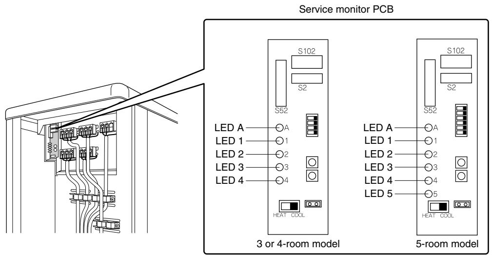
(R17270)
There are a green LED (LED A) and red LEDs on the outdoor unit PCB. The LED A indicates microcomputer operation condition. In normal condition, the LED A is blinking and the other LEDs are OFF.
Even after the error is canceled and the unit operates in normal condition, the LED indication remains.
- Problem Symptoms and Measures
| Problem Symptom | Check Item | Details of Measure | Reference Page |
| None of the units operates. | Check the power supply. | Check if the rated voltage is supplied. | — |
| Check the types of the indoor units. | Check if the indoor unit type is compatible with the outdoor unit. | — |
| Check the outdoor temperature. | Heating operation cannot be used when the outdoor temperature is 20°C or higher, and cooling operation cannot be used when the outdoor temperature is below -10 ~ 10°C (depending on the model). | — |
| Diagnose with remote controller indication | — | 267 |
| Check the remote controller addresses. | Check if address settings for the remote controller and indoor unit are correct. | 415 |
| Operation sometimes stops. | Check the power supply. | A power failure of 2 to 10 cycles can stop air conditioner operation. (Operation lamp OFF) | — |
| Check the outdoor temperature. | Heating operation cannot be used when the outdoor temperature is 20°C or higher, and cooling operation cannot be used when the outdoor temperature is below -10 ~ 10°C (depending on the model). | — |
| Diagnose with remote controller indication. | — | 267 |
| Some indoor units do not operate. | Check the type of the indoor units. | Check if the indoor unit type is compatible with the outdoor unit. | — |
| Diagnose with remote controller indication | — | 267 |
| Units operate but do not cool, or do not heat. | Check for wiring and piping errors in the connection between the indoor and outdoor units. | Conduct the wiring/ piping error check described on the product diagnosis nameplate. | — |
| Check for thermistor detection errors. | Check if the thermistor is mounted securely. | — |
| Check for faulty operation of the outdoor electronic expansion valve. | Set all the units to cooling operation, and compare the temperatures of the liquid pipes to see if the each outdoor electronic expansion valve works. | — |
| Diagnose with remote controller indication. | — | 267 |
| Diagnose by service port pressure and operating current. | Check for refrigerant shortage. | 296 |
| Large operating noise and vibrations | Check the output voltage of the power module. | — | 335 |
| Check the power module. | — | — |
| Check the installation condition. | Check if the required spaces for installation (specified in the installation manual) are provided. | — |
3. Service Check Function
3.1 RA Indoor Unit - FTXG, FTXS, CTXS, FVXG, FVXS, FLXS, FDXS Series
3.1.1 ARC466 Series Remote Controller
Check Method 1
- When the timer cancel button is held down for 5 seconds, 空 is displayed on the temperature display screen.

- Press the timer cancel button repeatedly until a long beep sounds.
The code indication changes in the sequence shown below.
| No. | Code | No. | Code | No. | Code |
| 1 | 00 | 13 | C7 | 25 | U8 |
| 2 | U4 | 14 | B3 | 26 | U4 |
| 3 | L5 | 15 | H8 | 27 | P4 |
| 4 | E6 | 16 | H3 | 28 | L3 |
| 5 | H6 | 17 | C9 | 29 | L4 |
| 6 | H3 | 18 | C4 | 30 | H7 |
| 7 | R8 | 19 | C5 | 31 | U2 |
| 8 | E7 | 20 | J3 | 32 | E8 |
| 9 | U3 | 21 | J6 | 33 | R4 |
| 10 | F3 | 22 | E5 | 34 | F8 |
| 11 | R5 | 23 | R1 | 35 | H1 |
| 12 | F6 | 24 | E1 | 36 | P9 |
| No. | Code | No. | Code | No. | Code |
| 1 | 00 | 14 | C7 | 27 | U8 |
| 2 | U4 | 15 | R3 | 28 | U4 |
| 3 | L5 | 16 | H8 | 29 | P4 |
| 4 | E6 | 17 | H3 | 30 | L3 |
| 5 | H6 | 18 | C9 | 31 | L4 |
| 6 | H3 | 19 | C4 | 32 | H7 |
| 7 | R5 | 20 | C5 | 33 | U2 |
| 8 | E7 | 21 | C6 | 34 | E8 |
| 9 | U0 | 22 | J3 | 35 | R4 |
| 10 | F3 | 23 | J6 | 36 | F8 |
| 11 | R5 | 24 | E5 | 37 | H1 |
| 12 | F6 | 25 | R1 | 38 | P3 |
| 13 | R3 | 26 | E1 | | |
i Note:
- A short beep and two consecutive beeps indicate non-corresponding codes.
- To return to the normal mode, hold the timer cancel button down for 5 seconds. When the remote controller is left untouched for 60 seconds, it also returns to the normal mode.
- Not all the error codes are displayed. When you cannot find the error code, try the check method 2. ( Refer to page 255.)
Check Method 2
- Press the center of the [Temp] button and the [Mode] button at the same time.

5C is displayed on the LCD.

- Select 5 (service check) with the [Temp] or button.
- Press the [Mode] button to enter the service check mode.

The left-side number blinks.

- Press the [Temp] or button and change the number until you hear the two consecutive beeps or the long beep.

- Diagnose by the sound.
beep : The left-side number does not correspond with the error code.
tow consecutive beeps : The left-side number corresponds with the error code but the right-side number does not.
long beep: Both the left-side and right-side numbers correspond with the error code. The numbers indicated when you hear the long beep are the error code. Error codes and description Refer to page 267.
- Press the [Mode] button.

The right-side number blinks.

- Press the [Temp] or button and change the number until you hear the long beep.

- Diagnose by the sound.
beep : The left-side number does not correspond with the error code.
two consecutive beeps : The left-side number corresponds with the error code but the right-side number does not.
long beep: Both the left-side and right-side numbers correspond with the error code.
- Determine the error code.
The numbers indicated when you hear the long beep are the error code.
Error codes and description Refer to page 267.
- Press the [Mode] button for 5 seconds to exit from the service check mode.
(When the remote controller is left untouched for 60 seconds, it returns to the normal mode also.)

3.1.2 ARC452 Series Remote Controller
Check Method 1
- When the timer cancel button is held down for 5 seconds, 空 is displayed on the temperature display screen.


(R14554)
- Press the timer cancel button repeatedly until a long beep sounds.
The code indication changes in the sequence shown below.
| No. | Code | No. | Code | No. | Code |
| 1 | 00 | 13 | C7 | 25 | U8 |
| 2 | U4 | 14 | R3 | 26 | U4 |
| 3 | L5 | 15 | H8 | 27 | P4 |
| 4 | E6 | 16 | K9 | 28 | L3 |
| 5 | X6 | 17 | C9 | 29 | L4 |
| 6 | X0 | 18 | C4 | 30 | H7 |
| 7 | R6 | 19 | C5 | 31 | U2 |
| 8 | E7 | 20 | J3 | 32 | E8 |
| 9 | U0 | 21 | J5 | 33 | R8 |
| 10 | F3 | 22 | E5 | 34 | F8 |
| 11 | R5 | 23 | R1 | | |
| 12 | F6 | 24 | E1 | | |
i Note:
- A short beep or 2 consecutive beeps indicate non-corresponding codes.
- To return to the normal mode, hold the timer cancel button down for 5 seconds. When the remote controller is left untouched for 60 seconds, it also returns to the normal mode.
- Not all the error codes are displayed. When you cannot find the error code, try the check method 2. ( Refer to page 258.)
Check Method 2
- Press the 3 buttons ([TEMP] , [TEMP] , [MODE]) at the same time to enter the diagnosis mode.

The left-side number blinks.

- Press the [TEMP] or button and change the number until you hear the two consecutive beeps or the long beep.

- Diagnose by the sound.
beep: The left-side number does not correspond with the error code.
two consecutive beeps : The left-side number corresponds with the error code but the right-side number does not.
long beep: Both the left-side and right-side numbers correspond with the error code. The numbers indicated when you hear the long beep are the error code. Error codes and description Refer to page 267.
- Press the [MODE] button.

The right-side number blinks.

- Press the [TEMP] or button and change the number until you hear the long beep.

- Diagnose by the sound.
beep: The left-side number does not correspond with the error code.
two consecutive beeps : The left-side number corresponds with the error code but the right-side number does not.
long beep : Both the left-side and right-side numbers correspond with the error code.
- Determine the error code.
The numbers indicated when you hear the long beep are the error code.
Error codes and description Refer to page 267.
- Press the [MODE] button to exit from the diagnosis mode.

The display ^* means the trial operation mode.
Refer to page 408 for trial operation.

- Press the [ON/OFF] button twice to return to the normal mode.
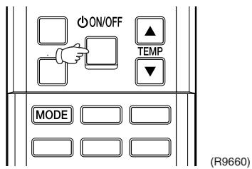
i Note: When the remote controller is left untouched for 60 seconds, it returns to the normal mode.
3.1.3 ARC433 Series Remote Controller
Check Method 1
- When the timer cancel button is held down for 5 seconds, 空 is displayed on the temperature display screen.

- Press the timer cancel button repeatedly until a long beep sounds.
The code indication changes in the sequence shown below.
| No. | Code | No. | Code | No. | Code |
| 1 | 00 | 12 | C7 | 23 | H3 |
| 2 | U4 | 13 | H8 | 24 | E1 |
| 3 | F3 | 14 | J3 | 25 | P4 |
| 4 | E6 | 15 | R3 | 26 | L3 |
| 5 | L5 | 16 | R1 | 27 | L4 |
| 6 | R5 | 17 | C4 | 28 | H6 |
| 7 | E5 | 18 | C5 | 29 | H7 |
| 8 | F6 | 19 | H3 | 30 | U2 |
| 9 | C9 | 20 | J6 | 31 | U4 |
| 10 | U3 | 21 | U8 | 32 | E8 |
| 11 | E7 | 22 | R5 | 33 | R4 |

- A short beep or two consecutive beeps indicate non-corresponding codes.
- To return to the normal mode, hold the timer cancel button down for 5 seconds. When the remote controller is left untouched for 60 seconds, it also returns to the normal mode.
- Not all the error codes are displayed. When you cannot find the error code, try the check method 2. ( Refer to page 261.)
Check Method 2
- Press the center of the [TEMP] button and the [MODE] button at the same time to enter the diagnosis mode.

The left-side number blinks.

- Press the [TEMP] or button and change the number until you hear the two consecutive beeps or the long beep.

- Diagnose by the sound.
beep: The left-side number does not correspond with the error code.
two consecutive beeps : The left-side number corresponds with the error code but the right-side number does not.
long beep: Both the left-side and right-side numbers correspond with the error code. The numbers indicated when you hear the long beep are the error code. Error codes and description Refer to page 267.
- Press the [MODE] button.

The right-side number blinks.

- Press the [TEMP] or button and change the number until you hear the long beep.

- Diagnose by the sound.
beep: The left-side number does not correspond with the error code.
two consecutive beeps : The left-side number corresponds with the error code but the right-side number does not.
long beep : Both the left-side and right-side numbers correspond with the error code.
- Determine the error code.
The numbers indicated when you hear the long beep are the error code.
Error codes and description Refer to page 267.
- Press the [MODE] button to exit from the diagnosis mode.

The display ^ means the trial operation mode. Refer to page 408 for trial operation.

- Press the [ON/OFF] button twice to return to the normal mode.


Note: When the remote controller is left untouched for 60 seconds, it returns to the normal mode.
3.2 SA Indoor Unit - FCQG, FFQ, FHQ, FDBQ, FBQ Series
3.2.1 Relations between Modes
BRC1D528
The following modes can be selected by using the [Inspection / Test] button on the remote controller.


BRC1E52A7, BRC1E52B7
3.2.2 BRC1D528
If operation stops due to malfunction, the operation lamp on the remote controller blinks, and error code is displayed. (Even if stop operation is carried out, malfunction contents are displayed when inspection mode is entered.) The error code enables you to tell what kind of malfunction caused operation to stop.
Refer to page 267 for error code and malfunction contents.


- When you press the [INSPECTION/TEST OPERATION] button, the inspection display blinks.
- While in the inspection mode, press the [ON/OFF] button for 5 seconds or more to clear the failure history indication. In this case, the error code blinks twice and then changes to 空 (= Normal), the UNIT No. changes to 空 , and the operation mode automatically switches from the inspection mode to the normal mode (displaying the set temperature).
3.2.3 BRC1E52A7, BRC1E52B7
The following display appears on the screen when a error (or a warning) occurs during operation.
Check the error code and take the corrective action specified for the particular model.

(1) Check if it is error or warning.
| Operation status | Display |
| Abnormal shutdown | The system stops operating. | The operation lamp (green) starts to blink. The message "Error: Press Menu Button" appears and blinks at the bottom of the screen. | Cool
Set temperature
28°C
Error: Press Menu Button
(R12858) |
| Warning | The system continues its operation. | The operation lamp (green) remains on. The message "Warning: Press Menu Button" appears and blinks at the bottom of the screen. | Cool
Set temperature
28°C
Warning: Press Menu Button
(R12857) |
(2) Take corrective action.
- Press the [Menu/Enter] button to check the error code.

- Take the corrective action specific to the model.

(R12859)
4. Code Indication on Remote Controller
4.1 RA Indoor Unit - FTXG, FTXS, CTXS, FVXG, FVXS, FLXS, FDXS Series
| Error Codes | Description | Reference Page |
| CC | Normal condition | — |
| A1 | Indoor unit PCB abnormality | 270 |
| A5 | Freeze-up protection control or heating peak-cut control | 272 |
| A6 | Fan motor or related abnormality | DC motor (wall, floor standing) | 274 |
| AC motor (floor / ceiling, duct) | 277 |
| A9 | Radiant panel temperature rise, indoor electronic expansion valve (motor operated valve) abnormality, freeze-up protection control (FVXG series only) | 278 |
| C4 | Indoor heat exchanger thermistor or related abnormality | 280 |
| C7 | Front panel open / close fault (FTXG series only) | 281 |
| C9 | Room temperature thermistor or related abnormality | 280 |
| C6 | Radiant panel thermistor or related abnormality (FVXG series only) | 280 |
| U4 | Signal transmission error (between indoor unit and outdoor unit) | 282 |
| UR | Unspecified voltage (between indoor unit and outdoor unit) | 283 |
4.2 SA Indoor Unit - FCQG, FFQ, FHQ, FDBQ, FBQ Series
| Error Codes | Description | Reference Page |
| 00 | Normal condition | — |
| A1 | Indoor unit PCB abnormality | 284 |
| A3 | Drain water level system abnormality | 285 |
| A6 | Fan motor or related abnormality | 287 |
| A7 | Swing motor lock (FHQ series only) | 289 |
| A5 | Drain system abnormality | 290 |
| C4 | Indoor heat exchanger thermistor or related abnormality | 291 |
| C5 | Room temperature thermistor or related abnormality | 291 |
| CJ | Remote controller thermistor abnormality | 292 |
| U5 | Signal transmission error (between indoor unit and remote controller) | 293 |
| U8 | Signal transmission error (between MAIN remote controller and SUB remote controller) | 294 |
| UR | Field setting abnormality | 295 |
: Error code displays automatically and system stops.
Inspect and solve the error.
: In the case of the shaded error codes, "inspection" is not displayed. The system
operates, but be sure to inspect and solve the error.
4.3 Sub Codes for SA Indoor Unit
If an error code like the one shown below is displayed when the navigation remote controller (BRC1E52A7, BRC1E52B7) is in use, make a detailed diagnosis or a diagnosis of the relevant unit referring to the attached list.
| Error codes | Description | Troubleshooting |
| A6 - 01 | Fan motor locked | A locked fan motor current has been detected.
Turn the fan by hand to check for the connection of connectors. |
| A6 - 10 | Fan overcurrent error | A fan motor overcurrent has been detected.
Check for the connection of the connector between the fan motor and the PCB. If the connection is normal, replace the fan motor. If this still cannot solve the error, replace the PCB. |
| A6 - 11 | Fan position detection error | An error in the detection of position of the fan motor. Check for the connection of the connector between the fan motor and the PCB. If the connection is normal, replace the fan motor. If this still cannot solve the error, replace the PCB. |
| AH - 03 | Transmission error (between the self-cleaning decoration panel and the indoor unit)
[when the self-cleaning decoration panel is mounted] | Check for the connection of the harness connector between the panel PCB and the indoor unit PCB. |
| AH - 04 | Dust detection sensor error
[when the self-cleaning decoration panel is mounted] | Check for the connections of the connector X12A on the panel PCB and the connectors X18A and X19A on the sensor PCBs. |
| AH - 05 | Dust collection sign error
[when the self-cleaning decoration panel is mounted] | Check for clogging with dust at the dust collection port as well as in the brush unit, S-shaped pipe, and dust box. Furthermore, check for any stains of the light receiving and emitting parts of the infrared unit. |
| AH - 06 | Air filter rotation error
[when the self-cleaning decoration panel is mounted] | Check for anything getting in the way of rotating the filter (e.g. the filter comes off or the drive gear is clogged with foreign matters). |
| AH - 07 | Damper rotation error
[when the self-cleaning decoration panel is mounted] | The damper does not rotate normally. Check for any foreign matters around the damper and for the operation of the gear and limit switch. |
| AH - 08 | Filter self-cleaning operation error
[when the self-cleaning decoration panel is mounted] | The unit has not yet completed the filter self-cleaning operation even after the lapse of specified period of time. Check for any external noise, etc. |
| AH - 09 | Filter self-cleaning operation start disabled error
[when the self-cleaning decoration panel is mounted] | The unit has been put into a state in which the filter self-cleaning operation is disabled. Check the unit for the operating conditions. |
| C6 - 01 | Faulty combination of indoor unit PCB and fan PCB | A combination of indoor unit PCB and fan PCB is defective. Check whether the capacity setting adaptor is correct and the type of the fan PCB is correct. |
4.4 Outdoor Unit
:ON, :OFF, 串 :Blinks
Green : Blinks in normal condition Red : OFF in normal condition
| Outdoor Unit LED Indication | Error Codes | Description | Reference Page |
| Green | Red |
| A | 1 | 2 | 3 | 4 | 5★ | | | |
| Φ | ● | ● | ● | ● | ● | CC | Normal condition | — |
| UR | Unspecified voltage (between indoor unit and outdoor unit) | 301 |
| UH | Anti-icing function in other rooms | 301 |
| Φ | ● | ● | ○ | ○ | ● | (UC) | Refrigerant shortage | 296 |
| Φ | ○ | ● | ● | ○ | ● | U2 | Low-voltage detection or over-voltage detection | 298 |
| Φ | ● | ○ | ○ | ○ | ● | U7 | Signal transmission error (on outdoor unit PCB) | 300 |
| Φ | ○ | ● | ○ | ○ | ● | AS | Anti-icing function | 302 |
| Φ | ○ | ○ | ○ | ● | ● | E1 | Outdoor unit PCB abnormality | 304 |
| Φ | ○ | ● | ○ | ● | ● | (ES) | OL activation (compressor overload) | 305 |
| Φ | ● | ○ | ○ | ● | ● | (ES) | Compressor lock | 306 |
| Φ | ○ | ○ | ○ | ○ | ● | EN | DC fan lock | 307 |
| Φ | ● | ○ | ● | ○ | ● | EB | Input overcurrent detection | 308 |
| Φ | ○ | ● | ○ | ● | ● | F3 | Discharge pipe temperature control | 309 |
| Φ | ○ | ● | ○ | ○ | ● | F6 | High pressure control in cooling | 310 |
| Φ | ○ | ○ | ● | ● | ● | HO | Compressor sensor system abnormality | 311 |
| HG | Position sensor abnormality | 313 |
| HG | CT or related abnormality | 315 |
| HG | Outdoor temperature thermistor or related abnormality | 317 |
| J3 | Discharge pipe thermistor or related abnormality | 317 |
| J6 | Outdoor heat exchanger thermistor or related abnormality | 317 |
| J8 | Liquid pipe thermistor or related abnormality | 317 |
| J9 | Gas pipe thermistor or related abnormality | 317 |
| P4 | Radiation fin thermistor or related abnormality | 317 |
| Φ | ○ | ○ | ● | ○ | ● | L3 | Electrical box temperature rise | 319 |
| Φ | ● | ● | ● | ○ | ● | L4 | Radiation fin temperature rise | 321 |
| Φ | ● | ● | ○ | ● | ● | L5 | Output overcurrent detection | 323 |

-
The error codes in the parenthesis ( ) are displayed only when the system is shut down.
-
When a sensor error occurs, check the remote controller display to determine which sensor is malfunctioning.
If the remote controller does not indicate the error code, conduct the following procedure.
-
Turn the power switch off and back on again. If the same LED indication appears again immediately after the power is turned on, the fault is in the thermistor.
-
If the above condition does not result, the fault is in the CT.
-
The indoor unit error code may take the precedence in the remote controller display.
- 3-room models and 4-room models do not have LED5.
5. Troubleshooting for RA Indoor Unit - FTXG, FTXS, CTXS, FVXG, FVXS, FLXS, FDXS Series
5.1 Indoor Unit PCB Abnormality
| Remote Controller Display | R1 |
| Method of Malfunction Detection | The system checks if the circuit works properly within the microcomputer of the indoor unit. |
| Malfunction Decision Conditions | The system cannot set the internal settings. |
| Supposed Causes | ■ Wrong models interconnected
■ Defective indoor unit PCB
■ Disconnection of connector
■ Reduction of power supply voltage |
Troubleshooting

(R15310)

Check the following connector.
| Model Type | Connector |
| Wall mounted type | Terminal board ~ Control PCB |
| Floor standing type | Terminal board ~ Control PCB |
| Floor / ceiling suspended dual type | S36 ~ S37 |
| Duct connected type | Terminal board ~ Control PCB |
5.2 Freeze-up Protection Control or Heating Peak-cut Control
| Remote Controller Display | 85 |
| Method of Malfunction Detection | ■ Freeze-up protection control
During cooling operation, the freeze-up protection control (operation halt) is activated according to the temperature detected by the indoor heat exchanger thermistor.
■ Heating peak-cut control
During heating operation, the temperature detected by the indoor heat exchanger thermistor is used for the heating peak-cut control (operation halt, outdoor fan stop, etc.) |
| Malfunction Decision Conditions | ■ Freeze-up protection control
During cooling operation, the indoor heat exchanger temperature is below 0°C.
■ Heating peak-cut control
During heating operation, the indoor heat exchanger temperature is above 65°C. |
| Supposed Causes | ■ Short-circuited air
■ Clogged air filter of the indoor unit
■ Dust accumulation on the indoor heat exchanger
■ Defective indoor heat exchanger thermistor
■ Defective indoor unit PCB |
Troubleshooting

Check No.01
Refer to P.325

Caution
Be sure to turn off the power switch before connecting or disconnecting connectors, or parts may be damaged.

(R15715)
5.3.1 DC Motor (Wall Mounted Type, Floor Standing Type)
| Remote Controller Display | 86 |
| Method of Malfunction Detection | The rotation speed detected by the Hall IC during fan motor operation is used to determine abnormal fan motor operation. |
| Malfunction Decision Conditions | The detected rotation speed does not reach the demanded rotation speed of the target tap, and is less than 50% of the maximum fan motor rotation speed. |
| Supposed Causes | ■ Disconnection of connector
■ Foreign matters stuck in the fan
■ Layer short inside the fan motor winding
■ Breaking of wire inside the fan motor
■ Breaking of the fan motor lead wires
■ Defective capacitor of the fan motor
■ Defective indoor unit PCB |
Troubleshooting

Check No.02
Refer to P.326
FTXG, FTXS-J, FTXS-G, FVXG, FVXS Series

Troubleshooting

Check No.03
Refer to P.326
FTXS-K, CTXS-K Series

Caution
Be sure to turn off the power switch before connecting or disconnecting connectors, or parts may be damaged.

5.3.2 AC Motor (Duct Connected Type, Floor / Ceiling Suspended Dual Type)
| Remote Controller Display | IEC |
| Method of Malfunction Detection | The rotation speed detected by the Hall IC during fan motor operation is used to determine abnormal fan motor operation. |
| Malfunction Decision Conditions | The detected rotation speed does not reach the demanded rotation speed of the target tap, and is less than 50% of the maximum fan motor rotation speed. |
| Supposed Causes | ■ Layer short inside the fan motor winding
■ Breaking of wire inside the fan motor
■ Breaking of the fan motor lead wires
■ Defective capacitor of the fan motor
■ Defective indoor unit PCB |
Troubleshooting

Check No.04
Refer to P.327

Caution
Be sure to turn off the power switch before connecting or disconnecting connectors, or parts may be damaged.

5.4 Radiant Panel Temperature Rise, Indoor Electronic Expansion Valve (Motor Operated Valve) Abnormality, Freeze-up Protection Control (FVXG Series Only)
| Remote Controller Display | 83 |
| Method of Malfunction Detection | Radiant panel temperature rise
During RADIANT operation, high temperature control (e.g., operation halt, indoor electronic expansion valve closure) is activated according to the temperature detected by the radiant panel thermistors. |
| Indoor electronic expansion valve abnormality
■ The indoor electronic expansion valve is required to be fully closed during cooling, dry or heating operation. When the indoor electronic expansion valve is open due to malfunction, the refrigerant flows into the radiant panel and the radiant panel temperature rises or drops.
■ The indoor electronic expansion valve is required to be open during RADIANT operation. When the indoor electronic expansion valve is closed due to malfunction, the refrigerant does not flow into the radiant panel and the radiant panel temperature does not rise.
■ For multi system
The indoor electronic expansion valve is required to be fully closed in the room where the system does not run. When the indoor electronic expansion valve is open due to malfunction and heating or RADIANT operation is conducted in the other room(s), the refrigerant flows into the radiant panel and the radiant panel temperature rises. |
| Freeze-up protection control
The temperature detected by the radiant panel thermistors is used to prevent the indoor unit from freezing during cooling operation. |
| Malfunction Decision Conditions | Radiant panel temperature rise
The radiant panel surface temperature calculated by the radiant panel thermistors is above 70°C. |
| Indoor electronic expansion valve abnormality
■ During cooling or dry operation, the temperature detected by the radiant panel thermistor (φ 4) has dropped.
■ During heating operation, the temperature detected by the radiant panel thermistor (φ 4) has risen.
■ During RADIANT operation, the temperature detected by the radiant panel thermistor (φ 4) does not rise.
■ For multi system
While the system does not run and heating or RADIANT operation is conducted in the other room(s), the temperature detected by the radiant panel thermistor (φ 4) has risen. |
| Freeze-up protection control
During cooling operation, the operation stops when the temperature detected by the radiant panel thermistor (φ 4) has dropped. |
| Supposed Causes | Clogged air filter of the indoor unit
Dust accumulation on the indoor heat exchanger
Short-circuited air
Defective radiant panel thermistor(s)
Defective indoor heat exchanger thermistor
Defective room temperature thermistor
Defective indoor electronic expansion valve (or coil) |
Troubleshooting

Check No.01
Refer to P.325

Check No.06
Refer to P.327

Caution
Be sure to turn off the power switch before connecting or disconnecting connectors, or parts may be damaged.
Check the operation condition.
- When the outdoor temperature is below the lower limit for cooling operation (10^) , the freeze-up protection control is activated and the cooling operation stops.
Condition OK?
NO
Start operation within the specified range of the outdoor temperature.
YES
Check No. 06
Check the indoor electronic expansion valve coil.
OK?
NO
Replace the indoor electronic expansion valve coil.
YES
Check No. 01
-Radiant panel thermistors
-Indoor heat exchanger thermistor
- Room temperature thermistor
Does it
conform to the thermistor characteristic chart?
NO
Replace the thermistor.
ck the air passage.
Is there any short circuit?
YES
Provide sufficient air passage.
.
Is it very dirty?
YES
Clean the air filter.
NO
Check the indoor heat exchanger.
YES
Is it very dirty?
YES
Clean the indoor heat exchanger.
NO
Change the refrigerant to remove moisture from the piping (after drawing a vacuum).
NO
Error repeats?
NO
Completed.
YES
Replace the indoor unit PCB.
NO
Error repeats?
Completed.
Replace the indoor heat exchanger.
(R14647)
| Remote Controller Display | C4, C3, CE |
| Method of Malfunction Detection | The temperatures detected by the thermistors are used to determine thermistor errors. |
| Malfunction Decision Conditions | The thermistor input is more than 4.96 V or less than 0.04 V during compressor operation. |
| Supposed Causes | ■ Disconnection of connector
■ Defective thermistor
■ Defective indoor unit PCB |
Troubleshooting

Check No.01
Refer to P.325
Caution Be sure to turn off the power switch before connecting or disconnecting connectors, or parts may be damaged.

^4 : Indoor heat exchanger thermistor
C9: Room temperature thermistor
: Radiant panel thermistor (FVXG series only)
5.6 Front Panel Open / Close Fault (FTXG Series Only)
| Remote Controller Display | □□ |
| Method of Malfunction Detection | |
| Malfunction Decision Conditions | ■ If the error repeats, the system is shut down. |
| Supposed Causes | ■ Defective reduction motor
■ Malfunction or deterioration of the front panel mechanism
■ Defective limit switch |
Troubleshooting

(R17249)

Note: You cannot operate the unit by the remote controller when the front panel mechanism breaks down.
- Turn off the power.
- Remove the front panel.
- Turn on the power.
(Wait until the initialization finishes.)
- Operate the unit by the indoor unit [ON/OFF] button.
5.7 Signal Transmission Error (between Indoor Unit and Outdoor Unit)
| Remote Controller Display | |
| Method of Malfunction Detection | The data received from the outdoor unit in indoor unit-outdoor unit signal transmission is checked whether it is normal. |
| Malfunction Decision Conditions | The data sent from the outdoor unit cannot be received normally, or the content of the data is abnormal. |
| Supposed Causes | ■ Wiring error
■ Breaking of the connection wires between the indoor and outdoor units (wire No. 3)
■ Defective outdoor unit PCB
■ Defective indoor unit PCB
■ Disturbed power supply waveform |
Troubleshooting

Check No.11
Refer to P.328

(R15782)
5.8 Unspecified Voltage (between Indoor Unit and Outdoor Unit)
| Remote Controller Display | |
| Method of Malfunction Detection | The supply power is detected for its requirements (different from pair type and multi type) by the indoor / outdoor transmission signal. |
| Malfunction Decision Conditions | The pair type and multi type are interconnected. |
| Supposed Causes | Wrong models interconnected
Wrong wiring of connecting wires
Wrong indoor unit PCB or outdoor unit PCB mounted
Defective indoor unit PCB
Defective outdoor unit PCB |
Troubleshooting

6. Troubleshooting for SA Indoor Unit - FCQG, FFQ, FHQ, FDBQ, FBQ Series
6.1 Indoor Unit PCB Abnormality
| Remote Controller Display | R1 |
| Method of Malfunction Detection | The system checks the data from EEPROM. |
| Malfunction Decision Conditions | When the data from the EEPROM is not received correctlyEEPROM (Electrically Erasable Programmable Read Only Memory): A memory chip that holds its content without power. It can be erased, either within the computer or externally and usually requires more voltage for erasure than the common +5 volts used in logic circuits. It functions like non-volatile RAM, but writing to EEPROM is slower than writing to RAM. |
| Supposed Causes | ■ Defective indoor unit PCB |
Troubleshooting

Caution
Be sure to turn off the power switch before connecting or disconnecting connectors, or parts may be damaged.

6.2 Drain Water Level System Abnormality
| Remote Controller Display | 83 |
| Method of Malfunction Detection | The float switch detects error. |
| Malfunction Decision Conditions | When the water level reaches its upper limit and when the float switch turns OFF |
| Supposed Causes | Defective drain pumpImproper drain piping workClogged drain pipingDefective float switchDefective indoor unit PCBDefective short circuit connector X15A on indoor unit PCB |
Troubleshooting

(R17250)

If 3 is detected by the indoor unit PCB which is not mounted with X15A, the indoor unit PCB is defective.
| Remote Controller Display | |
| Method of Malfunction Detection | The signal from the fan motor detects abnormal fan speed. |
| Malfunction Decision Conditions | When the fan rotations are not detected while the output voltage to the fan is at its maximum |
| Supposed Causes | ■ Defective indoor fan motor
■ Broken or disconnected wire
■ Defective contact
■ Defective indoor unit PCB |
Troubleshooting
FCQC, FFQ, FDBQ, FBQ Series

tion
Be sure to turn off the power switch before connecting or disconnecting connectors, or parts may be damaged.
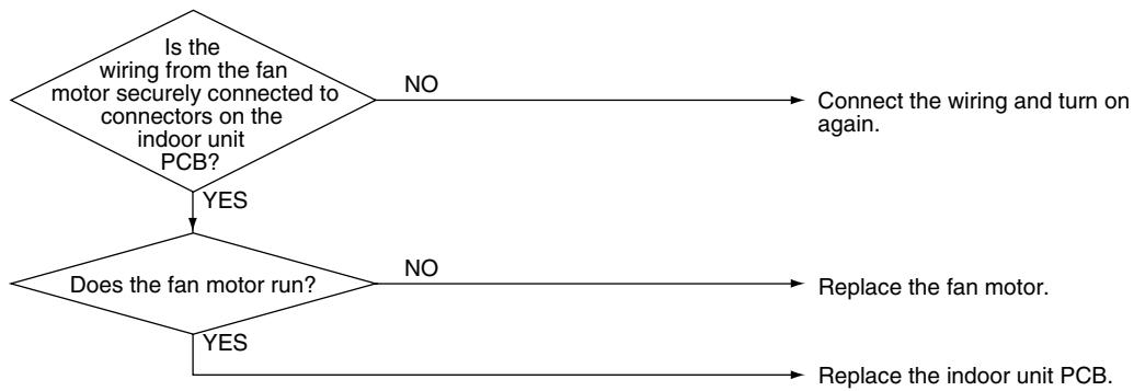
(R11296)
Troubleshooting
FHQ Series

Be sure to turn off the power switch before connecting or disconnecting connectors, or parts may be damaged.

(R12862)

Note: There is a possibility of open phase power supply, also check the power supply.
6.4 Swing Motor Lock (FHQ Series Only)
| Remote Controller Display | 87 |
| Method of Malfunction Detection | The error is detected by the limit switch when the motor turns. |
| Malfunction Decision Conditions | When the ON/OFF micro-switch for position detection cannot be reversed even though the swing motor is energized for a specified amount of time (about 30 seconds). |
| Supposed Causes | Defective swing motorDefective micro-switchDisconnection of connectorDefective indoor unit PCB |
Troubleshooting

(R17251)
6.5 Drain System Abnormality
| Remote Controller Display | RF |
| Method of Malfunction Detection | Water leakage is detected based on the float switch ON/OFF changeover while the compressor is not operating. |
| Malfunction Decision Conditions | When the float switch changes from ON to OFF while the compressor is OFF |
| Supposed Causes | ■ Error in the drain pipe installation
■ Defective float switch
■ Defective indoor unit PCB |
Troubleshooting

Caution
Be sure to turn off the power switch before connecting or disconnecting connectors, or parts may be damaged.


| Remote Controller Display | 4, 9 |
| Method of Malfunction Detection | The temperatures detected by the thermistors determine thermistor errors. |
| Malfunction Decision Conditions | The thermistor input is more than 4.96 V or less than 0.04 V during compressor operation. |
| Supposed Causes | Disconnection of connector Defective thermistor Defective indoor unit PCB |
Troubleshooting

Check No.01
Refer to P.325
If the cause of the problem is related to the thermistors, the thermistors should be checked prior to changing the indoor unit PCB.
To check the thermistors, proceed as follows:
| Step | Action |
| 1 | Disconnect the thermistor from the indoor unit PCB. |
| 2 | Read the temperature and the resistance value. |
| 3 | Check if the measured values correspond with the values in the table of thermistor resistance check. |

tion
Be sure to turn off the power switch before connecting or disconnecting connectors, or parts may be damaged.

^ 4 : Indoor heat exchanger thermistor (R2T, R3T)
C9: Room temperature thermistor (R1T)
6.7 Remote Controller Thermistor Abnormality
| Remote Controller Display | L L |
| Method of Malfunction Detection | Even if remote controller thermistor is faulty, system is possible to operate by system thermistor. Malfunction detection is carried out by the temperature detected by remote controller thermistor. |
| Malfunction Decision Conditions | When the remote controller thermistor becomes disconnected or shorted while the unit is running. |
| Supposed Causes | ■ Defective thermistor
■ Broken wire |
Troubleshooting

(R17252)

To delete the record of error codes, press the [ON/OFF] button for 4 seconds or more while the error code is displayed in the inspection mode.
6.8 Signal Transmission Error (between Indoor Unit and Remote Controller)
| Remote Controller Display | 123 |
| Method of Malfunction Detection | Microcomputer checks if transmission between indoor unit and remote controller is normal. |
| Malfunction Decision Conditions | Normal transmission does not continue for specified period. |
| Supposed Causes | ■ Connection of 2 main remote controllers (when using 2 remote controllers)
■ Defective indoor unit PCB
■ Defective remote controller
■ Transmission error caused by noise |
Troubleshooting

6.9 Signal Transmission Error (between MAIN Remote Controller and SUB Remote Controller)
| Remote Controller Display | LBC |
| Method of Malfunction Detection | In case of controlling with 2 remote controllers, check the system using micro-computer if signal transmission between indoor unit and remote controller (main and sub) is normal. |
| Malfunction Decision Conditions | Normal transmission does not continue for specified period. |
| Supposed Causes | ■ Remote controller is set to “SUB” when using 1 remote controller
■ Connection of 2 sub remote controllers (when using 2 remote controllers)
■ Defective remote controller PCB |
Troubleshooting

6.10 Field Setting Abnormality
| Remote Controller Display | L10 |
| Method of Malfunction Detection | |
| Malfunction Decision Conditions | Incorrect field setting |
| Supposed Causes | ■ Defective indoor unit PCB
■ Defective outdoor unit PCB
■ Defective power supply PCB
■ Indoor-outdoor, indoor-indoor unit transmission wiring
■ Defective remote controller wiring |
Troubleshooting

(R17253)
7. Troubleshooting for Outdoor Unit
7.1 Refrigerant Shortage
| Remote Controller Display | CC |
| Outdoor Unit LED Display | A 1 2 3 4 5 |
| Method of Malfunction Detection | Refrigerant shortage detection I : Refrigerant shortage is detected by checking the input current value and the compressor output frequency. If the refrigerant is short, the input current is smaller than the normal value. Refrigerant shortage detection II : Refrigerant shortage is detected by checking the discharge pipe temperature and the opening of the outdoor electronic expansion valve. If the refrigerant is short, the discharge pipe temperature tends to rise. |
| Malfunction Decision Conditions | Refrigerant shortage detection I : The following conditions continue for 7 minutes.
◆ DC current ≤ A × Compressor output frequency + B
◆ Output frequency > C |
| A (-) | B (A) |
| 40/50/52/58 class | 0.01 | 0.3 |
| 68/75 class | 0.035 | 0.5 |
| 80/90 class | 0.027 | 2.0 |
| Refrigerant shortage detection II : The following conditions continue for 80 seconds.
◆ Opening of the outdoor electronic expansion valve ≥ D
◆ Discharge pipe temperature > E × target discharge pipe temperature + F |
| D (pulse) | E (-) |
| Cooling | 450 | 255/256 |
| Heating | 40 |
| If the error repeats, the system is shut down.
Reset condition: Continuous run for about 60 minutes without any other error |
| Supposed Causes | Disconnection of the discharge pipe thermistor, indoor or outdoor heat exchanger thermistor, room or outdoor temperature thermistor
Closed stop valve
Refrigerant shortage (refrigerant leakage)
Poor compression performance of compressor
Defective outdoor electronic expansion valve |
Troubleshooting

Check No.01
Refer to P.325

Check No.12
Refer to P.329

Caution
Be sure to turn off the power switch before connecting or disconnecting connectors, or parts may be damaged.

(R17254)
7.2 Low-voltage Detection or Over-voltage Detection
| Remote Controller Display | 12 |
| Outdoor Unit LED Display | A 1 2 3 4 5 |
| Method of Malfunction Detection | ★ Indoor Unit |
| The zero-cross detection of the power supply is evaluated by the indoor unit PCB. |
| ★ Outdoor Unit |
| Low-voltage detection: An abnormal voltage drop is detected by the DC voltage detection circuit. |
| Over-voltage detection: An abnormal voltage rise is detected by the over-voltage detection circuit. |
| Malfunction Decision Conditions | ★ Indoor Unit |
| There is no zero-cross detection in approximately 10 seconds. |
| ★ Outdoor Unit |
| Low-voltage detection: The voltage detected by the DC voltage detection circuit is below 150 V for 0.1 second. If the error repeats, the system is shut down. Reset condition: Continuous run for about 60 minutes without any other error |
| Over-voltage detection: An over-voltage signal is fed from the over-voltage detection circuit to the microcomputer. The compressor stops if the error occurs, and restarts automatically after 3-minute standby. |
| Supposed Causes | Supply voltage is not as specified. Defective DC voltage detection circuit Defective over-voltage detection circuit Defective PAM control part Disconnection of compressor harness Noise Momentary fall of voltage Momentary power failure Defective indoor unit PCB |
Troubleshooting
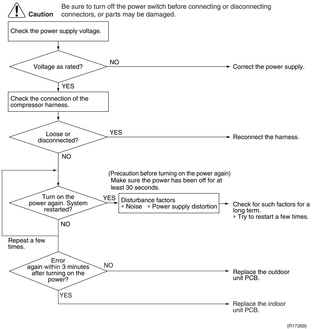
7.3 Signal Transmission Error (on Outdoor Unit PCB)
| Remote Controller Display | 12345 |
| Outdoor Unit LED Display | A 1 2 3 4 5 |
| Method of Malfunction Detection | Communication error between microcomputer mounted on the main PCB and PM1. |
| Malfunction Decision Conditions | The abnormality is determined when the data sent from the PM1 can not be received for 9 seconds.
The error counter is reset when the data from the PM1 can be successfully received. |
| Supposed Causes | Defective outdoor unit PCB |
Troubleshooting

Caution
Be sure to turn off the power switch before connecting or disconnecting connectors, or parts may be damaged.

(R7185)
7.4 Unspecified Voltage (between Indoor Unit and Outdoor Unit) / Anti-icing Function in Other Rooms
| Remote Controller Display | UH, UH |
| Outdoor Unit LED Display | A 1 2 3 4 5 |
| Method of Malfunction Detection | A wrong connection is detected by checking the combination of indoor and outdoor units on the microcomputer. |
| Malfunction Decision Conditions | ■ Anti-icing function in other rooms
■ Unspecified internal and/or external voltages
■ Mismatching of indoor and outdoor units |
| Supposed Causes | ■ Anti-icing function in other rooms
■ Wrong models interconnected
■ Wrong indoor unit PCB or outdoor unit PCB mounted |
Troubleshooting


Refer to "Anti-icing function" on page 302 for detail.
7.5 Anti-icing Function
| Remote Controller Display | 85 |
| Outdoor Unit LED Display | A 1 2 3 4 5 |
| Method of Malfunction Detection | During cooling operation, indoor unit icing is detected by checking the temperatures sensed by the indoor heat exchanger thermistor and room temperature thermistor that are located in a shut-down room. |
| Malfunction Decision Conditions | In cooling operation, the both conditions (A) and (B) are met for 5 minutes.
(A) Room temperature – Indoor heat exchanger temperature ≥ 10°C
(B) Indoor heat exchanger temperature ≤ -1°C
If the error repeats, the system is shut down.
Reset condition: Continuous run for about 60 minutes without any other error |
| Supposed Causes | Wrong wiring or piping
Defective outdoor electronic expansion valve
Short-circuited air
Defective indoor heat exchanger thermistor
Defective room temperature thermistor |
Troubleshooting

Check No.01
Refer to P.325

Check No.12
Refer to P.329

7.6 Outdoor Unit PCB Abnormality
| Remote Controller Display | E |
| Outdoor Unit LED Display | A 1 2 3 4 5 |
| Method of Malfunction Detection | Detect within the program of the microcomputer. |
| Malfunction Decision Conditions | The program of the microcomputer is in abnormal running order. |
| Supposed Causes | Defective outdoor unit PCB Noise Momentary fall of voltage Momentary power failure |
Troubleshooting

(R7183)
7.7 OL Activation (Compressor Overload)
| Remote Controller Display | ES |
| Outdoor Unit LED Display | A 1 2 3 4 5 |
| Method of Malfunction Detection | A compressor overload is detected through compressor OL. |
| Malfunction Decision Conditions | If the error repeats, the system is shut down.
Reset condition: Continuous run for about 60 minutes without any other error
* The operating temperature condition is not specified. |
| Supposed Causes | Defective discharge pipe thermistor
Defective outdoor electronic expansion valve or coil
Defective four way valve or coil
Defective outdoor unit PCB
Refrigerant shortage
Water mixed in refrigerant
Defective stop valve |
Troubleshooting

Check No.01
Refer to P.325

Check No.12
Refer to P.329

Check No.13
Refer to P.330

Check No.14
Refer to P.330

7.8 Compressor Lock
| Remote Controller Display | ES |
| Outdoor Unit LED Display | A 1 2 3 4 5 |
| Method of Malfunction Detection | A compressor lock is detected by checking the compressor running condition through the position detection circuit. |
| Malfunction Decision Conditions | ■ Judging from the current waveform generated when high-frequency voltage is applied to the compressor.
■ If the error repeats, the system is shut down.
■ Reset condition: Continuous run for about 5 minutes without any other error |
| Supposed Causes | ■ Compressor locked
■ Compressor harness disconnected |
Troubleshooting

Check No.15
Refer to P.331

Caution
Be sure to turn off the power switch before connecting or disconnecting connectors, or parts may be damaged.
(Precaution before turning on the power again)
Make sure the power has been off for at least 30 seconds.

7.9 DC Fan Lock
| Remote Controller Display | E |
| Outdoor Unit LED Display | A 1 2 3 4 5 |
| Method of Malfunction Detection | An error is determined with the high-voltage fan motor rotation speed detected by the Hall IC. |
| Malfunction Decision Conditions | The fan does not start in 30 seconds even when the fan motor is running.
If the error repeats, the system is shut down.
Reset condition: Continuous run for about 5 minutes without any other error |
| Supposed Causes | Disconnection of the fan motor
Foreign matter stuck in the fan
Defective fan motor
Defective outdoor unit PCB |
Troubleshooting

Check No.16
Refer to P.332

| Remote Controller Display | EB |
| Outdoor Unit LED Display | A 1 2 3 4 5 |
| Method of Malfunction Detection | Detected by checking the input current value |
| Malfunction Decision Conditions | The input current is at a certain value (depending on the condition) for 2.5 seconds.
The compressor halts if the error occurs, and restarts automatically after 3-minute standby. |
| Supposed Causes | Outdoor temperature is out of operation range.
Defective compressor
Defective power module
Defective outdoor unit PCB
Short circuit |
| Troubleshooting
Check No.15 Refer to P.331
Check No.17 Refer to P.333
Check No.18 Refer to P.333 | Be sure to turn off the power switch before connecting or disconnecting connectors, or parts may be damaged.
* An input overcurrent may result from wrong internal wiring. If the system is interrupted by an input overcurrent after the wires have been disconnected and reconnected for part replacement, check the wiring again.
Check No.17 Check the installation condition.
Start operation and measure the input current.
Input current flowing above its stop level?
NO
Replace the outdoor unit PCB.
Turn off the power and disconnect the harnesses U, V, and W.
* Inverter checker Part No.: 1225477
Any LED off?
YES
Correct the power supply or replace the outdoor unit PCB.
Turn off the power, and reconnect the harnesses. Turn on the power again and start operation.
Check No.18 Check the discharge pressure. |
7.11 Discharge Pipe Temperature Control
| Remote
Controller
Display | F3 |
| Outdoor Unit LED
Display | A 1 2 3 4 5 |
| Method of
Malfunction
Detection | Detected by the discharge pipe thermistor |
| Malfunction
Decision
Conditions | If the temperature detected by the discharge pipe thermistor rises above A °C, the compressor stops.
The error is cleared when the discharge pipe temperature is dropped below B °C. |
| A (°C) | B (°C) |
| 40/50/52/58 class | 110 | 95 |
| 68/75/80/90 class | 120 | 107 |
| ■ If the error repeats, the system is shut down.
■ Reset condition: Continuous run for about 60 minutes without any other error |
| Supposed
Causes | Defective discharge pipe thermistor
(Defective outdoor heat exchanger thermistor or outdoor temperature thermistor)
Defective outdoor electronic expansion valve or coil
Refrigerant shortage
Defective four way valve
Water mixed in refrigerant
Defective stop valve
Defective outdoor unit PCB |
| Troubleshooting | Caution Be sure to turn off the power switch before connecting or disconnecting connectors, or parts may be damaged.
Check No. 01 NG
Check the thermistors.
OK
Check No. 12 NG
Check the outdoor electronic expansion valve.
OK
Check No. 14 NG
Check the refrigerant line.
OK
* Refrigerant shortage
* Four way valve
* Water mixed
* Stop valve
Replace the outdoor unit PCB. |
7.12 High Pressure Control in Cooling
| Remote
Controller
Display | F6 |
| Outdoor Unit LED
Display | A 1 2 3 4 5 |
| Method of
Malfunction
Detection | High-pressure control (operation halt, frequency drop, etc.) is activated in cooling mode if the temperature sensed by the outdoor heat exchanger thermistor exceeds the limit. |
| Malfunction
Decision
Conditions | The temperature sensed by the outdoor heat exchanger thermistor rises above about 65°C.
The error is cleared when the temperature drops below about 50°C. |
| Supposed
Causes | The installation space is not large enough.
Dirty outdoor heat exchanger
Defective outdoor fan motor
Defective stop valve
Defective outdoor electronic expansion valve or coil
Defective outdoor heat exchanger thermistor
Defective outdoor unit PCB |
| Troubleshooting | Caution Be sure to turn off the power switch before connecting or disconnecting connectors, or parts may be damaged.
Check the installation space.
Check the installation condition.
Check No. 17
Check the installation condition.
NG
Change the installation location or direction.
Clean the outdoor heat exchanger.
Replace the fan motor.
Reconnect the connector or fan motor lead wires.
Replace the stop valve.
Replace the outdoor electronic expansion valve or the coil.
Replace the outdoor unit PCB.
Replace the outdoor heat exchanger thermistor.
Replace the outdoor unit PCB. |
| Check No.01
Refer to P.325 |
| Check No.12
Refer to P.329 |
| Check No.17
Refer to P.333 |
| Check No.18
Refer to P.333 |
| Check No.19
Refer to P.334 |
7.13 Compressor Sensor System Abnormality
| Remote Controller Display | |
| Outdoor Unit LED Display | A 1 2 3 4 5 |
| Method of Malfunction Detection | Fault condition is identified by the supply voltage and the DC voltage which is detected before the compressor startup.
Fault condition is identified by the compressor current which is detected right after the compressor startup.
If the error repeats, the system is shut down.
Reset condition: Continuous run for about 5 minutes without any other error |
| Malfunction Decision Conditions | The detected value of the supply voltage and the DC voltage is obviously low or high.
The compressor current does not run when the compressor is started. |
| Supposed Causes | Disconnection of reactor
Disconnection of compressor harness
Defective outdoor unit PCB
Defective compressor |
Troubleshooting

7.14 Position Sensor Abnormality
| Remote Controller Display | |
| Outdoor Unit LED Display | A 1 2 3 4 5 |
| Method of Malfunction Detection | A compressor startup failure is detected by checking the compressor running condition through the position detection circuit. |
| Malfunction Decision Conditions | If the error repeats, the system is shut down.
Reset condition: Continuous run for about 5 minutes without any other error |
| Supposed Causes | Disconnection of the compressor relay cable
Defective compressor
Defective outdoor unit PCB
Start-up failure caused by the closed stop valve
Input voltage is outside the specified range. |
Troubleshooting

Check No.15
Refer to P.331

Check No.18
Refer to P.333

Caution
Be sure to turn off the power switch before connecting or disconnecting connectors, or parts may be damaged.

| Remote Controller Display | H3 |
| Outdoor Unit LED Display | A 1 2 3 4 5 |
| Method of Malfunction Detection | A CT or related error is detected by checking the compressor running frequency and CT-detected input current. |
| Malfunction Decision Conditions | The compressor running frequency is more than A Hz and input current is less than B A. |
| A (Hz) | B (A) |
| 40/50/52/58/68/75 class | 55 | 0.5 |
| 80/90 class | 32 | 0.5 |
| If the error repeats, the system is shut down.
Reset condition: Continuous run for about 60 minutes without any other error |
| Supposed Causes | Defective power module
Broken or disconnected wiring
Defective reactor
Defective outdoor unit PCB |
Troubleshooting

Check No.15
Refer to P.331

Check No.21
Refer to P.334

Caution
Be sure to turn off the power switch before connecting or disconnecting connectors, or parts may be damaged.

| Remote Controller Display | 43, 43, 45, 48, 49, 54 |
| Outdoor Unit LED Display | A 1 2 3 4 5 |
| Method of Malfunction Detection | This type of error is detected by checking the thermistor input voltage to the microcomputer. A thermistor error is detected by checking the temperature sensed by each thermistor. |
| Malfunction Decision Conditions | ■ The thermistor input is above 4.96 V or below 0.04 V with the power on.
■ 43 error is judged if the discharge pipe temperature is lower than the heat exchanger temperature.
■ The system is shut down if all the units are judged as the 43 error. |
| Supposed Causes | ■ Disconnection of the connector for the thermistor
■ Defective thermistor corresponding to the error code
■ Defective heat exchanger thermistor in the case of 43 error (outdoor heat exchanger thermistor in cooling operation, or indoor heat exchanger thermistor in heating operation)
■ Defective outdoor unit PCB |
| Troubleshooting | In case of 44
Caution Be sure to turn off the power switch before connecting or disconnecting connectors, or parts may be damaged.
Replace the outdoor unit PCB.
44 : Radiation fin thermistor |
Troubleshooting

Check No.01
Refer to P.325
In case of H9, U3, U6, U8, U9

(R17164)
43: Outdoor temperature thermistor
3 : Discharge pipe thermistor
J5: Outdoor heat exchanger thermistor
JB: Liquid pipe thermistor
3: Gas pipe thermistor
7.17 Electrical Box Temperature Rise
| Remote Controller Display | L3 |
| Outdoor Unit LED Display | A 1 2 3 4 5 |
| Method of Malfunction Detection | An electrical box temperature rise is detected by checking the radiation fin thermistor with the compressor off. |
| Malfunction Decision Conditions | ■ With the compressor off, the radiation fin temperature is above A °C.
■ The error is cleared when the temperature drops below B °C.
■ To cool the electrical components, the outdoor fan starts when the radiation fin temperature rises above C °C and stops when it drops below B °C. |
| A (°C) | B (°C) | C (°C) |
| 100 | 70 | 85 |
| Supposed Causes | ■ Defective outdoor fan motor
■ Short circuit
■ Defective radiation fin thermistor
■ Disconnection of connector
■ Defective outdoor unit PCB |
Troubleshooting

Check No.17
Refer to P.333

Check No.19
Refer to P.334

Caution
Be sure to turn off the power switch before connecting or disconnecting connectors, or parts may be damaged.

| Remote Controller Display | L4 |
| Outdoor Unit LED Display | A 1 2 3 4 5 |
| Method of Malfunction Detection | A radiation fin temperature rise is detected by checking the radiation fin temperature with the compressor on. |
| Malfunction Decision Conditions | ■ The radiation fin temperature with the compressor on is above A °C.
■ The error is cleared when the temperature drops below B °C |
| A (℃) | B (℃) |
| 40/50/52/58/68/75 class | 103 | 95 |
| 80/90 class | 105 | 97 |
| ■ If the error repeats, the system is shut down.
■ Reset condition: Continuous run for about 60 minutes without any other error |
| Supposed Causes | ■ Defective outdoor fan motor
■ Short circuit
■ Defective radiation fin thermistor
■ Disconnection of connector
■ Defective outdoor unit PCB
■ Silicon grease is not applied properly on the radiation fin after replacing the outdoor unit PCB. |
Troubleshooting

Check No.17
Refer to P.333

Check No.19
Refer to P.334

Caution
Be sure to turn off the power switch before connecting or disconnecting connectors, or parts may be damaged.

| A (°C) |
| 40/50/52/58/68/75 class | 103 |
| 80/90 class | 105 |

Refer to "Application of silicon grease to a power transistor and a diode bridge" on page 423 for detail.
7.19 Output Overcurrent Detection
| Remote Controller Display | LS |
| Outdoor Unit LED Display | A 1 2 3 4 5 |
| Method of Malfunction Detection | An output overcurrent is detected by checking the current that flows in the inverter DC section. |
| Malfunction Decision Conditions | A position signal error occurs while the compressor is running.A speed error occurs while the compressor is running.An output overcurrent signal is fed from the output overcurrent detection circuit to the microcomputer.If the error repeats, the system is shut downRESET condition: Continuous run for about 5 minutes without any other error |
| Supposed Causes | Poor installation conditionClosed stop valveDefective power moduleWrong internal wiringAbnormal power supply voltageDefective outdoor unit PCBDefective compressor |
Troubleshooting

Check No.15
Refer to P.331

Check No.17
Refer to P.333

Check No.18
Refer to P.333

Check No.22
Refer to P.335

Caution
Be sure to turn off the power switch before connecting or disconnecting connectors, or parts may be damaged.
- An output overcurrent may result from wrong internal wiring. If the system is interrupted by an output overcurrent after the wires have been disconnected and reconnected for part replacement, check the wiring again.

8. Check
8.1 Thermistor Resistance Check
Check No.01
Disconnect the connectors of the thermistors from the PCB, and measure the resistance of each thermistor using tester.
The relationship between normal temperature and resistance is shown in the table and the graphs below.
The data is for reference purpose only.
| Thermistor temperature (°C) | Resistance (kΩ) |
| Room temperature thermistor for FTXS-K and CTXS-K series | Other thermistors |
| -20 | 70.3 | 197.8 |
| -15 | 56.1 | 148.2 |
| -10 | 44.1 | 112.1 |
| -5 | 34.9 | 85.60 |
| 0 | 28.2 | 65.93 |
| 5 | 22.3 | 51.14 |
| 10 | 18.1 | 39.99 |
| 15 | 14.8 | 31.52 |
| 20 | 12.2 | 25.02 |
| 25 | 10.0 | 20.00 |
| 30 | 8.3 | 16.10 |
| 35 | 6.9 | 13.04 |
| 40 | 5.8 | 10.62 |
| 45 | 4.9 | 8.707 |
| 50 | 4.1 | 7.176 |
(R25^ = 10k ,B = 3435K) (R25^ = 20k ,B = 3950K)

Room temperature thermistor
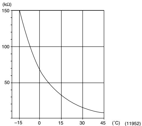
Other thermistors


(R11906)
- The room temperature thermistor is directly mounted on the display PCB. Remove the display PCB from the control PCB to measure the resistance.
- When the indoor heat exchanger thermistor is soldered on the PCB, remove the thermistor and measure the resistance.
8.2 Fan Motor Connector Check
Check No.02
FTXG, FTXS-J, FTXS-G, FVXG, FVXS Series
- Check the connection of connector.
- Check motor power supply voltage output (pins 4 - 7).
- Check motor control voltage (pins 4 - 3).
- Check rotation command voltage output (pins 4 - 2).
- Check rotation pulse input (pins 4 - 1).

(R14225)
Check No.03
FTXS-K, CTXS-K Series
Fan motor wire breakdown / short circuit check
- Check the connector for connection.
- Turn the power off.
- Check if each resistance at the phases U - V and V - W is 90 100 (between the pins 12 - 9, and between 9 - 6).
Motor control voltage check
- Check the connector for connection.
- Check the motor control voltage is generated (between the pins 2 - 3).
Rotation pulse check
- Check the connector for connection.
- Turn the power on and stop the operation.
- Check if the Hall IC generates the rotation pulse 4 times when the fan motor is manually rotated once (between the pins 1 - 3).

8.3 Hall IC Check
Check No.04
FLXS, FDXS Series
- Check the connector connection.
- With the power on, operation off, and the connector connected, check the following.
*Output voltage of about 5 V between pins 1 and 3.
*Generation of 3 pulses between pins 2 and 3 when the fan motor is operating.
If NG in step 1 Defective PCB Replace the PCB.
If NG in step 2 Defective Hall IC Replace the fan motor.
If OK in both steps 1 and 2 Replace the PCB.

8.4 Indoor Electronic Expansion Valve Coil Check
Check No.06
Conduct the followings to check the indoor electronic expansion valve coil (EV).
- Check to see if the EV connector is correctly connected to the PCB.
- Turn the power off and on again, and check to see if the EV generate latching sound.
- If the EV does not generate latching sound in the above step 2, disconnect the connector and check the continuity using a tester.
- Check the continuity between the pins 1 - 6, 2 - 6, 3 - 6, and 4 - 6. If there is no continuity between the pins, the EV coil is faulty.

- If the continuity is confirmed in the above step 3, the PCB is faulty.

Please note that the latching sound varies depending on the valve type.
Check No.11
Measure the power supply waveform between No. 1 and No. 2 on the terminal board, and check the waveform disturbance.
- Check to see if the power supply waveform is a sine wave (Fig.1).
Check to see if there is waveform disturbance near the zero cross (sections circled in Fig.2)

[Fig.1]
[Fig.2]
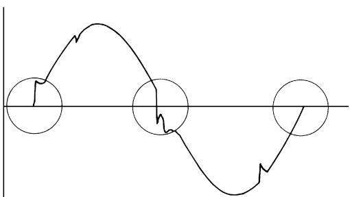
(R1736)
(R1444)
8.6 Outdoor Electronic Expansion Valve Check
Check No.12
Conduct the followings to check the outdoor electronic expansion valve (EV).
- Check to see if the EV connector is correctly inserted in the PCB. Match the EV unit number and the connector number.
- Turn the power off and on again, and check to see if all the EVs generate latching sound.
- If any of the EVs does not generate latching sound in the above step 2, disconnect that connector and check the continuity using a tester.
Check the continuity between the pins 1 - 6 and 3 - 6, and between the pins 2 - 5 and 4 - 5. If there is no continuity between the pins, the EV coil is faulty.
- If no EV generates latching sound in the above step 2, the outdoor unit PCB is faulty.
- If the continuity is confirmed in the above step 3, mount a good coil (which generated latching sound) in the EV unit that did not generate latching sound, and check to see if that EV generates latching sound.
If latching sound is generated, the outdoor unit PCB is faulty.
If latching sound is not generated, the EV unit is faulty.

Note: Please note that the latching sound varies depending on the valve type.
If the system keeps operating with a defective outdoor electronic expansion valve, the following problem may occur.
| Valve opening position | Possible problem | Check method |
| Open | Cooling:
■ Flowing noise of refrigerant in the unit which is not in operation
■ Water leakage at the unit which is not in operation
■ Operation half due to anti-icing function | Reset power supply and conduct cooling operation unit by unit.
Check the liquid pipe temperature of no-operation unit.
Almost the same as the outdoor temperature?
NO
The EV is not defective.
Replace the EV of the room.
(R16019) |
| Heating:
■ Flowing noise of refrigerant in the unit which is not in operation
■ The unit does not heat the room. |
| Close | Cooling:
■ The problem unit does not cool the room.
■ Only the problem unit is in operation, the unit starts pump down.
(The low pressure of the unit becomes vacuum.)
■ Abnormal discharge pipe temperature | Reset power supply and conduct cooling operation unit by unit.
Check the low pressure.
Does the pressure become into vacuum zone?
NO
The EV is not defective.
Replace the EV of the room.
(R16020) |
| Heating:
■ Refrigerant shortage due to stagnation of liquid refrigerant inside the faulty indoor unit
■ The unit does not heat the room.
■ Abnormal discharge pipe temperature |
Check No.13


(R11904)
8.8 Inverter Unit Refrigerant System Check
Check No.14

8.9 “Inverter Checker” Check
Check No.15
Characteristics
If abnormal stop occurs due to compressor startup failure or overcurrent output when using an inverter unit, it is difficult to judge whether the stop is caused by the compressor failure or some other failure (control PCB, power module, etc.). The inverter checker makes it possible to judge the cause of trouble easily and securely. (Connect this checker as a quasi-compressor instead of the compressor and check the output of the inverter.)
Operation Method
Step 1
Be sure to turn the power off.
Step 2
Install the inverter checker instead of a compressor.
Note:
Make sure the charged voltage of the built-in smoothing electrolytic capacitor drops to 10 VDC or below before carrying out the service work.

Reference:
If the terminals of the compressor are not FASTON terminals (difficult to remove the wire on the terminals), it is possible to connect wires available on site to the outdoor unit from output side of PCB. (Do not connect them to the compressor at the same time, otherwise it may result in incorrect detection.)
Step 3
Activate the power transistor test operation from the outdoor unit.
1) Press the forced operation [ON/OFF] switch for 5 seconds.
(Refer to page 405 for the position.)
Power transistor test operation starts.
Diagnose method (Diagnose according to 6 LEDs lighting status.)
(1) If all the LEDs are lit uniformly, the compressor is defective.
Replace the compressor.
(2) If the LEDs are not lit uniformly, check the power module.
Refer to Check No.22.
(3) If NG in Check No.22, replace the power module.
(Replace the main PCB. The power module is united with the main PCB.)
If OK in Check No.22, check if there is any solder cracking on the PCB.
(4) If any solder cracking is found, replace the PCB or repair the soldered section.
If there is no solder cracking, replace the PCB.

Caution
(1) When the output frequency is low, the LEDs blink slowly. As the output frequency increases, the LEDs blink quicker. (The LEDs look like they are lit.)
(2) On completion of the inverter checker diagnosis, be sure to re-crimp the FASTON terminals. Otherwise, the terminals may be burned due to loosening.

8.10 Rotation Pulse Check on the Outdoor Unit PCB
Check No.16
Make sure that the voltage of 320 ± 30V is applied.
- Set operation off and power off. Disconnect the connector S70.
- Check that the voltage between the pins 4 - 7 is 320 VDC.
- Check that the control voltage between the pins 3 - 4 is 15 VDC.
- Check that the rotation command voltage between the pins 2 - 4 is 0 15 VDC.
- Keep operation off and power off. Connect the connector S70.
- Check whether 2 pulses (0 ~ 15 VDC) are output at the pins 1 - 4 when the fan motor is rotated 1 turn by hand.
When the fuse is melted, check the outdoor fan motor for proper function.
If NG in step 2 Defective PCB Replace the PCB.
If NG in step 4 Defective Hall IC Replace the outdoor fan motor.
If OK in both steps 2 and 4 Replace the PCB.

8.11 Installation Condition Check
Check No.17

8.12 Discharge Pressure Check
Check No.18

8.13 Outdoor Fan System Check
Check No.19

8.14 Capacitor Voltage Check
Check No.21
Before this check, be sure to check the main circuit for short circuit.
With the circuit breaker still on, measure the voltage according to the drawing of the model in question. Be careful never to touch any live parts.
Multimeter
(DC. voltage range)

(R12869)
8.15 Power Module Check
Check No.22

Check to make sure that the voltage between (+) and (-) of the power module (PM1) is approx. 0V before checking.
- Disconnect the compressor harness connector from the outdoor unit PCB. To disengage the connector, press the protrusion on the connector.
- Follow the procedure below to measure resistance between the terminals of the power module and the terminals of the compressor with a multi-tester. Evaluate the measurement results referring to the following table.
| Negative (−) terminal of tester (positive terminal (+) for digital tester) | Power module (+) | UVW | Power module (−) | UVW |
| Positive (+) terminal of tester (negative terminal (−) for digital tester) | UVW | Power module (+) | UVW | Power module (−) |
| Resistance is OK. | several kΩ ~ several MΩ |
| Resistance is NG. | 0 Ω or ∞ |
- The illustration is for 40/50/52/58 class as representative.

(R16074)
Part 7
Removal Procedure
- Outdoor Unit: 40-75 Class 337
1.1 Removal of Outer Panels 337
1.2 Removal of Electrical Box 341
1.3 Removal of PCBs 349
1.4 Removal of Outdoor Fan / Fan Motor 354
1.5 Removal of Sound Blankets 356
1.6 Removal of Coils / Thermistors 360
1.7 Removal of Distributor 363
1.8 Removal of Four Way Valve 364
1.9 Removal of Compressor 365
- Outdoor Unit: 80/90 Class 367
2.1 Removal of Outer Panels 367
2.2 Removal of Electrical Box 382
2.3 Removal of PCBs 388
2.4 Removal of Fan Motor 392
2.5 Removal of Coils / Thermistors 393
2.6 Removal of Sound Blankets 399
2.7 Removal of Compressor 402
1. Outdoor Unit: 40-75 Class
Note: The illustrations are for heat pump models as representative.
1.1 Removal of Outer Panels
Procedure

Warning
Be sure to wait for 10 minutes or more after turning off all power supplies before disassembling work.
| Step | Procedure | Points |
| 1 | Appearance features | (R5494) | Take care not to cut your finger by the fins of the heat exchanger. |
| 2 | Remove the 4 screws (2 on both sides) of the top panel. | (R12898)Top panel(R12899) | |
| 3 | Remove the 6 screws of the front panel. | Front panel
(R17165) | |
| 4 | Remove the screw of the shield plate. | Shield plate
(R11204) | |
| 5 | Slide the shield plate to the left to unfasten the hooks and remove the shield plate. | (R5499) | |
| 6 | Unfasten the upper 2 hooks. | Align the position of hole of the upper hook to pull the front panel out. | |
| 7 | Lift the front panel up to unfasten the left side hooks. | (R5501) | The front panel has 3 hooks on the left. |
| 8 | Unfasten the right side hook and remove the front panel. | (R5503) |
| 9 | Remove the 4 screws of the discharge grille. | Discharge grille
(R12902) | |
| 10 | Remove the 2 screws of the stop valve cover. | Stop valve cover
(R11206) | |
| 11 | Slide the stop valve cover downward and remove it. | (R5506) | ■ When reassembling, make sure to fit the 5 hooks. |
1.2 Removal of Electrical Box
Procedure

Warning
Be sure to wait for 10 minutes or more after turning off all power supplies before disassembling work.
| Step | Procedure | Points |
| 1. Disconnect the harnesses. | Electrical box
Electronic expansion valve coil
Service port
A port
B port
C port
(R11175) | The illustrations are for 3-room models as representative, 4-room models also have D port. |
| 1 | Layout of the connecting wires |
| | Liquid pipe
Liquid stop valve
Gas stop valve
(R11176)
A port B port
Terminal board
Earth wire
(R17256) | The wires are fixed to the terminal board with screws. |
| 2 | Detach the fixing tape of the electrical box cover. | (Fixing tape(R5512)) | |
| 3 | Unfasten the 4 hooks at the▲mark of the electrical box cover. | (R5513) | |
| 4 | Lift the electrical box cover up and remove it. | (R5514) | |
| 5 | Detach the clamp and disconnect the connector for the fan motor [S70]. | [S70](R17166) | ■ When reassembling, insert the clamp into the either hole as below.For the ferrite core of fan motor harness(○○○○○○○○○○○○○○○○○○○○○○○○○○○○○○○○○○○○○○○○○○○○○○○○○○○○○○○○○○○○○○○○○○○○○○○○○○○○○○○○○○○○○○○○○○○○○○○○○○○○ |
| 6 | Release the fan motor lead wire from the hooks. | Fan motor lead wire (R17168) | [S20] (white): room A [S21] (red): room B [S22] (blue): room C
■ 4-room models also have [S23] (yellow) for room D.
■ When reassembling, insert the clamp of the electronic expansion valve coil ASSY into either hole as below.
○○○○○
○○○○○
○○○○○
○○○○○
Electronic expansion valve coil (R17170) |
| 7 | Disconnect the connectors for the electronic expansion valve coils. | [S20] [S21] [S22] (R5519) |
| 8 | Pull out the clamp. | (R5520) |
| 9 | Disconnect the connector for the overload protector [S40]. | [S40] (R5521) | |
| 10 | The wire harness for the compressor is attached to the partition plate by the clamp. | Partition plate Clamp (R12904) | |
| 11 | Pull out the clamp with pliers. | Clamp (R6423) | |
| 12 | Disconnect the relay connector of the compressor. | (R5522) | |
| 13 | Disconnect the each connector. | [S90] [S92] [S93] (R5523) | [S90]: Thermistors
[S92]: Gas pipe thermistors
[S93]: Liquid pipe thermistors |
| 14 | Disconnect the connector for the four way valve coil [S80]. | [R5524] (R5525) | ■ When reassembling, insert each clamp of the thermistor harnesses into the holes as below.
[S92]
○○○○○○○○○○○○○○○○○○○○○○○○○○○○○○○○○○○○○○○○○○○○○○○○○○○○○○○○○○○○○○○○○○○○○○○○○○○○○○○○○○○○○○○○○○○○○○○○○○○○ |
| 15 | The figure shows the arrangement of the wire harnesses under the electrical box. | (R5527) | ■ When reassembling, insert the clamp into the small hole. |
| 16 | Pull out the clamp of the thermistor lead wire. | Thermistor lead wire | Fixing position for the thermistor harness |
| 2. Remove the electrical box. | (R17257) | |
| 1 | Remove the 2 screws of the earth wires. |
| 2 | Remove the screws on the terminal board and disconnect all the connecting wires and power supply wire. | (R11178) | |
| 3 | Remove the 2 screws and remove the wiring fixture. | (R11180) | |
| 4 | Detach the outdoor temperature thermistor. | (R11181) | |
| 5 | Remove the screw on the right side of the electrical box. | (R5533) | |
| 6 | Remove the screw of the electrical box. | (R17259) | |
| 7 | Lift up and remove the electrical box. | (R5536) | |
1.3 Removal of PCBs
Procedure

Warning
Be sure to wait for 10 minutes or more after turning off all power supplies before disassembling work.
| Step | Procedure | Points |
| 1. Remove the service monitor PCB. | Service monitor PCB Terminal board (R5537) | |
| 1 | External appearance | | |
| 2 | Remove the screw of the terminal board and open it. | | |
| 3 | Disconnect the connectors [S52] [S102] from the service monitor PCB. | | |
| 4 | Unfasten the upper hook and pull the service monitor PCB upward to remove. | (R5541) Refer to page 40 for detail. |
| 2. Remove the main PCB. | [S10] [AC2] blue [AC1] brown (R5543) | [AC1] [AC2] : for power supply [S10] : for transmission |
| 1 | Disconnect the connectors for the terminal board on the right side. |
| 2 | Disconnect the 2 connectors for the reactor on the left side. | [HR2] [HR1] Reactor (R5544) | [AC1] [AC2] : for power supply [S10] : for transmission |
| 3 | Remove the 3 screws of the main PCB. | Main PCB (R5545) | |
| 4 | Unfasten the 3 hooks on the reactor side and slide the main PCB to the left. | (R5547) | |
| 5 | Release the relay harness for the compressor from the hook. | (R5548) | |
| 6 | Lift up the main PCB and remove it. | (R5549) | ■ In working, be careful not to break the main PCB with the excessive force because the main PCB and the radiation fin are adhered to one another. |
| | Relay harness for compressor Earth wire (R5550) | |
| 7 | Remove the 2 screws of the radiation fin. | [S70] [S40] [S20] [S21] [S22]
[S90] [S92] [S93] (R17260) | Refer to page 39 for detail. |
| Clamp for reactor harness (R11207) | ■ When reassembling, make sure to use the silicon grease.
■ Silicon grease Part No.: 1172698 |
| 8 | Remove the 3 screws of the reactor. | Radiation fin (R5553) |
| Reactor (R11208) |
| 3. Remove the terminal board. | Terminal board (back)
(R12907) | |
| 1 | Disconnect all the wire harnesses from the back of the terminal board. |
| 2 | Unfasten the hook of the electrical box and remove the terminal board. | (R5556) | |
| (R5557) | |
| (R5558) | |
1.4 Removal of Outdoor Fan / Fan Motor
Procedure

Warning
Be sure to wait for 10 minutes or more after turning off all power supplies before disassembling work.
| Step | Procedure | Points |
| 1 | Remove the 2 screws of the fan motor fixing plate. | Fan motor fixing plate (R12908) | Preparation
■ Remove the outer panels and plates.
■ Remove the electrical box. |
| 2 | Remove the fan motor fixing plate. |
| 3 | Remove the nut and remove the outdoor fan. | (R5561) Outdoor fan (R12909) | When reassembling, fit the lower hooks.
■ Nut size: M6
10 mm
(R12236)
■ When reassembling, align the▼mark of the outdoor fan with the D-cut section of the motor shaft. |
| 4 | Open the 2 hooks and release the fan motor lead wire. | Hook
(R17261)
(R17262) | ■ When reassembling, put the fan motor lead wire through the back of the fan motor so as not to be entangled with the outdoor fan.
Lead wire
Outdoor fan
(R12215) |
| 5 | Remove the 4 screws and remove the fan motor. | Fan motor
(R12913) | |
1.5 Removal of Sound Blankets
Procedure

Warning
Be sure to wait for 10 minutes or more after turning off all power supplies before disassembling work.
| Step | Procedure | Points |
| 1. Remove the right side panel. | Right side panel
(R12915) | Preparation
■ Remove the outer panels and plates.
■ Remove the electrical box. |
| 1 | Remove the 3 screws of the right side panel. |
| 2 | Remove the 2 screws on the back. |
| 3 | Remove the protection rubber. There is a hook on the back. | (R5571) |
| Protection rubber
(R5572) |
| 4 | Lift up and remove the right side panel. | (R5573) | |
| 2. Remove the partition plate. | Partition plate | |
| 1 | Remove the 2 screws of the partition plate. | | |
| 2 | Detach the clamp of the relay harness for the compressor. | (R5575)(R5576) | |
| 3 | Lift up and remove the partition plate. | (R5577) | ■ When reassembling, make sure to fit the lower hook of the partition plate. |
| 3. Remove the sound blankets. | Sound blanket (top upper) (R5579) | ■ Since the piping ports on the sound blanket are torn easily, remove the blanket carefully.
■ The shape of the sound blankets differs depending on the model. |
| 1 | Remove the sound blanket (top upper). |
| 2 | Remove the sound blanket (top inner). |
| 3 | Open the sound blanket (outer) and pull it out. | Sound blanket (outer)
(R5583) | |
| 4 | Open the sound blanket (inner) and pull it out. | Sound blanket (inner)
(R5584) | |
1.6 Removal of Coils / Thermistors
Procedure

Warning
Be sure to wait for 10 minutes or more after turning off all power supplies before disassembling work.
| Step | Procedure | Points |
| 1. Remove the electronic expansion valve coils. | Electronic expansion valve coil (R5588) | |
| 1 | Pull out the electronic expansion valve coils. |
| 2. Remove the four way valve coil. | Four way valve coil (R5589) | Cooling only models have no four way valve coil. |
| 1 | Remove the screw to remove the four way valve coil. |
| 3. Remove the thermistors. | Liquid pipe thermistor
(R11184) | ■ When reassembling, meet the edge of the thermistor and the fixture. |
| 1 | Open the putty and remove the liquid pipe thermistors. |
| 2 | Pull out the gas pipe thermistors. | Gas pipe thermistor
(R5591) | ■ Be careful not to lose the clip.
■ The positions of the clamp and outdoor heat exchanger thermistor differ depending on the model. |
| 3 | Cut the clamp.
Pull out the outdoor heat exchanger thermistor. | Clamp
Outdoor heat exchanger
thermistor
(R17171) |
| 4 | Remove the discharge pipe thermistor. | Clip
Discharge pipe thermistor
(R11185) | ■ When reassembling, meet the edge of the thermistor and the fixture. |
| 5 | Remove the assembly of thermistors. | Connector
Discharge pipe thermistor
(R5594) | |
1.7 Removal of Distributor
Procedure

Warning
Be sure to wait for 10 minutes or more after turning off all power supplies before disassembling work.
| Step | Procedure | Points |
| 1 | Remove the putty. | Putty (R5595) | Warning
Be careful not to get yourself burnt with the pipes and other parts that are heated by the gas brazing machine.
Warning
If the refrigerant gas leaks during work, ventilate the room. (If the refrigerant gas is exposed to flames, toxic gas may be generated.)
Caution
From the viewpoint of global environment protection, do not discharge the refrigerant gas in the atmosphere. Make sure to collect all the refrigerant gas.
Cautions for restoration
1. Restore the piping by non-oxidation brazing.
2. It is required to prevent the carbonization of the oil inside the four way valve and the deterioration of the gaskets affected by heat. (Keep below 120°C.) For the sake of this, wrap the four way valve with wet cloth and provide water so that the cloth does not dry.
In case of difficulty with gas brazing machine
1. Disconnect the brazed part where is easy to disconnect and restore.
2. Cut pipes on the main unit with a tube cutter in order to make it easy to disconnect. |
| ■ Before working, make sure that the refrigerant gas is empty in the circuit.
■ Be sure to apply nitrogen replacement when heating up the brazed part. |
| 2 | Heat up and disconnect the brazed parts to remove the distributor. | Brazed parts (R17263) |
| Note:
■ Do not use a metal saw for cutting pipes by all means because the sawdust comes into the circuit.
■ When withdrawing the pipes, be careful not to pinch them firmly with pliers. The pipes may get deformed.
■ Provide a protective sheet or a steel plate so that the brazing flame cannot influence peripheries. |
1.8 Removal of Four Way Valve
Procedure

Warning
Be sure to wait for 10 minutes or more after turning off all power supplies before disassembling work.
Step
Before working, make sure that the refrigerant gas is empty in the circuit.
- Be sure to apply nitrogen replacement when heating up the brazed part.
1
Remove the screw to remove the four way valve coil.
2
Heat up the 4 brazed part of the four way valve. First, disconnect the part (a).
3
Disconnect the part (b).
4
Disconnect the part (c) and (d) and remove the four way valve.
Note:
- Do not use a metal saw for cutting pipes by all means because the sawdust comes into the circuit.
- When withdrawing the pipes, be careful not to pinch them firmly with pliers. The pipes may get deformed.
- Provide a protective sheet or a steel plate so that the brazing flame cannot influence peripheries.
Procedure


Points
Cooling only models have no four way valve coil.

Warning
Be careful not to get yourself burnt with the pipes and other parts that are heated by the gas brazing machine.

Warning
If the refrigerant gas leaks during work, ventilate the room. (If the refrigerant gas is exposed to flames, toxic gas may be generated.)

Caution
From the viewpoint of global environment protection, do not discharge the refrigerant gas in the atmosphere. Make sure to collect all the refrigerant gas.
Cautions for restoration
- Restore the piping by nonoxidation brazing.
- It is required to prevent the carbonization of the oil inside the four way valve and the deterioration of the gaskets affected by heat. (Keep below 120^ .) For the sake of this, wrap the four way valve with wet cloth and provide water so that the cloth does not dry.
In case of difficulty with gas brazing machine
- Disconnect the brazed part where is easy to disconnect and restore.
- Cut pipes on the main unit with a tube cutter in order to make it easy to disconnect.
1.9 Removal of Compressor
Procedure

Warning
Be sure to wait for 10 minutes or more after turning off all power supplies before disassembling work.
| Step | Procedure | Points |
| 1 | Remove the terminal cover. | Terminal cover
(R12914) | |
| 2 | Disconnect the compressor lead wires. | V(yellow)
U(red)
W(blue)
(R5602) | |
| 3 | Detach the overload protector. | Overload protector
(R12916)
(R5604) | |
| 45 | Remove the putty.
Remove the 2 nuts. | (R5605)
Putty
(R17172) | Warning
Be careful not to get yourself burnt with the pipes and other parts that are heated by the gas brazing machine.
Warning
If the refrigerant gas leaks during work, ventilate the room. (If the refrigerant gas is exposed to flames, toxic gas may be generated.)
Warning
Since it may happen that the refrigerant oil in the compressor catches fire, prepare wet cloth so as to extinguish fire immediately.
Caution
From the viewpoint of global environment protection, do not discharge the refrigerant gas in the atmosphere. Make sure to collect all the refrigerant gas.
Cautions for restoration
1. Restore the piping by non-oxidation brazing.
2. It is required to prevent the carbonization of the oil inside the four way valve and the deterioration of the gaskets affected by heat. (Keep below 120°C.) For the sake of this, wrap the four way valve with wet cloth and provide water so that the cloth does not dry.
In case of difficulty with gas brazing machine
1. Disconnect the brazed part where is easy to disconnect and restore.
2. Cut pipes on the main unit with a tube cutter in order to make it easy to disconnect. |
| ■ Before working, make sure that the refrigerant gas is empty in the circuit.
■ Be sure to apply nitrogen replacement when heating up the brazed part. |
| 678 | Heat up the brazed part of the discharge side and disconnect the part (a).
Heat up the brazed part of the suction side and disconnect the part (b).
Remove the compressor. | (a)
(b)
(R14070) |
| Note:
■ Do not use a metal saw for cutting pipes by all means because the sawdust comes into the circuit.
■ When withdrawing the pipes, be careful not to pinch them firmly with pliers. The pipes may get deformed.
■ Provide a protective sheet or a steel plate so that the brazing flame cannot influence peripheries.
■ Be careful so as not to burn the compressor terminals, the name plate, the heat exchanger fin. | Compressor
(R12917) |
2. Outdoor Unit: 80/90 Class
Note: The illustrations are for heat pump models as representative.
2.1 Removal of Outer Panels
Procedure

Warning
Be sure to wait for 10 minutes or more after turning off all power supplies before disassembling work.
| Step | Procedure | Points |
| Appearance features | (R6368) | |
| 1. Remove the suction grille. | Rear side
(H14612)
Suction grille
(R6370) | The hooks are secured in the clearances of the outdoor heat exchanger fins. |
| 1 | Unfasten the 2 hooks at the bottom first. |
| 2 | Slide the suction grille downward to unfasten the 3 top hooks. | Hook
(R14613) | |
| 3 | Remove the suction grille. |
| 2. Remove the top panel. | Top panel
Left side panel
(R6373) | |
| 1 | Remove the 4 screws on the back and the screw on the left side panel. |
| 2 | Remove the 2 screws on the front and the screw on the right side panel. | (R6374) | |
| 3 | Lift the top panel and remove it. | (R6375) | |
| 3. Remove the right side panel. | (R6376) | |
| 1 | Remove the 5 screws. |
| 2 | Slide the right side panel downward to unfasten the 2 hooks on the back side. | (R6377)Hook
(R14614)Hook | |
| 3 | Remove the right side panel. | (R10441) | |
| 4. Remove the front panel (2). | Front Panel (2)
(R10629) | * This screw is M5 x 16 |
| 1 | Remove the 2 screws. |
| 2 | Slide the front panel (2) downward to unfasten the hook. | (R10374) | |
| 3 | Remove the front panel (2). | (R6383) | |
| 5. Remove the front panel (1). | Front Panel (1) (R10376) | Remove the discharge grille and outdoor fan first to remove the front panel (1). |
| 1 | Remove the 4 screws on the discharge grille. |
| 2 | Pull the bottom of the discharge grille. | (R10377) | |
| 3 | Slide the discharge grille downward to unfasten the 2 hooks at the top. | Hook
(R17173) | Nut size : M8
13 mm
(R12301)
When reassembling, align▼mark of the outdoor fan with D-cut section of the motor shaft. |
| 4 | Remove the discharge grille. |
| 5 | Remove the nut and remove the outdoor fan. |
| 6 | Remove the 2 screws on the partition plate (1). | Partition plate (1)
(R10382) | |
| 7 | Remove the screw at the bottom left of the front panel (1). | | |
| 8 | Remove the screw at the bottom of the left side. | (R6393) | |
| 9 | Remove the screw at the bottom of the back side. | (R6394) | |
| 10 | The front panel (1) has a hook. Lift the front panel (1). | ↑ | (Hook)
(R17174) |
| 11 | Remove the front panel (1). | (R10385) | ■ Be sure to detach the front panel (1) carefully so as not to deform it. |
| 6. Remove the rear panel. | |
| 1 | Remove the screw on the partition plate (2). | (R11209) | |
| 2 | Slide the partition plate (2) to the left and remove it. | (R11211) | |
| 3 | Remove the 5 screws on the wire fixing plate (upper). | Wire fixing plate (upper)
(R11210) | |
| 4 | Remove the wire fixing plate (upper). |
| 5 | Remove the 3 screws on the wire fixing plate (lower). | (R11213)
Wire fixing plate (lower)
(R11214) | |
| 6 | Remove the wire fixing plate (lower). | (R11215) | The holder is secured in the clearances of the outdoor heat exchanger fins. |
| 7 | Pull out the holder of the outdoor temperature thermistor. | Outdoor temperature thermistor (R10388) |
| 8 | Release the thermistor wire from the groove | Groove (R10389) |
| 9 | Remove the 3 screws on the rear panel. | (R10390) | |
| 10 | Remove the screw on the bottom frame. | (R10391) | |
| 11 | Remove the screw on the stop valve mounting plate. | (R10392) | |
| 12 | Lift the rear panel upward to unfasten the 2 hooks. | (R12918) | |
| 13 | Remove the rear panel. | (R10394) | |
2.2 Removal of Electrical Box
Procedure

Warning
Be sure to wait for 10 minutes or more after turning off all power supplies before disassembling work.
| Step | Procedure | Points |
| 1 | Remove the 2 screws to detach the earth wires. | (R10396) | |
| 2 | Disconnect the connector for the fan motor [S70]. | [S70] (R10397) | |
| 3 | Release the fan motor lead wire. | Fan motor lead wire (R17268) | : When reassembling, do not use these 2 hooks. |
| 4 | Disconnect the connector for the four way valve coil [S80]. | [S80]
Clamp
(R11187) | ■ Pull out the clamp.
■ The cooling only model has no harness for [S80]. |
| 5 | Disconnect the connectors for the electronic expansion valve coil.
[S20] (white): room A
[S21] (red): room B
[S22] (blue): room C
[S23] (yellow): room D | A B C D
Clamp
(R11188) | ■ Pull out the clamp.
■ 5-room models also has [S24] (green) for room E.
■ When reassembling, insert each clamp into the small hole.
For the electronic expansion valve coil
○○○○○○○○○○○○○○○○○○○○○○○○○○○○○○○○○○○○○○○○○○○○○○○○○○○○○○○○○○○○○○○○○○○○○○○○○○○○○○○○○○○○○○○○○○○○○○○○○○○○ |
| 6 | Disconnect the connector for the liquid pipe thermistor [S93]. | [S93]
Clamp
(R10400) | ■ Pull out the clamp. |
| 7 | Disconnect the connector for the gas pipe thermistor [S92]. | [S92] Clamp (R10537) | ■ Pull out the clamp.
■ When reassembling, insert the clamp into the small hole.
[S92]
○○○○○
○○○○○○
○○○○○○
(R17267) |
| 8 | Disconnect the connector for the thermistors [S90]. | [S90] Clamp (R10538) | ■ Pull out the clamp.
■ When reassembling, insert the clamp of the thermistor ASSY into the hole as below.
○○○○○○
○○○○○○
○○○○○○
Thermistor ASSY (R17142) |
| 9 | The wire harness of the thermistor is hooked under the electrical box. Unhook it and pull out the clamp. | [Hook] Clamp (R6420) | ■ When reassembling, insert the clamp into the small hole.
Fixing position for the thermistor harness |
| 10 | Disconnect the connector for the overload protector [S40]. | [S40]
(R10539) | |
| 11 | The wire harness for the compressor is attached to the partition plate (1) by the clamp. | Partition plate
Clamp
(R12904) | |
| 12 | Pull out the clamp with pliers. | Clamp
(R6423) | |
| 13 | Disconnect the relay connector of the compressor. | (R6469) | |
| 14 | Remove the screw on the stop valve mounting plate. | (R10395) | |
| 15 | Remove the screw on the partition plate (1). | (Partition plate (1)) | |
| 16 | Slide the electrical box leftward to unfasten the hook on the right side of the electrical box. | Hook
(R10401) | |
| 17 | Lift up the electrical box and remove it. | (R10402) | |
2.3 Removal of PCBs
Procedure

Warning
Be sure to wait for 10 minutes or more after turning off all power supplies before disassembling work.
| Step | Procedure | Points |
| 1. Remove the main PCB. | Hook
(H14617)
(R14617) | ■ Release the 4 hooks. The hooks are marked with ▼.
(R6427) |
| 1 | Remove the cover of the electrical box. |
| 2 | Remove the 3 screws. |
| 3 | Unfasten the 4 hooks. | Main PCB
(R10404)
(R10404) |
| 4 | Lift up the main PCB. | (R10405)
(R10405) |
| 5 | Disconnect the connectors. | U(red) V(yellow) W(blue) [S51] [S101]
[HR2](blue)
[HR1](white)
[AC2](blue)
[AC1](brown)
(R10407) | ■ [S51] [S101] : service monitor PCB
■ [S10] : terminal board (transmission)
■ [HR1] [HR2] : reactor
■ [AC1] [AC2] : terminal board (power supply)
■ [U] [V] [W] : compressor
■ Refer to page 40 for detail. |
| 6 | Remove the main PCB. |
| 2. Remove the reactor. | Reactor
(R10409) | |
| 1 | Remove the screw. |
| 2 | Remove the 3 screws and lift the reactor upward to remove it. |
| 3. Remove the service monitor PCB. | [S102]
(Service monitor PCB)
(R10410) | |
| 1 | Disconnect the connectors [S52]
[S102] from the service monitor PCB. |
| 2 | Slightly lift the top hook to detach. |
| 3 | Unfasten the bottom hook and remove the service monitor PCB. | (R6437)
(R6437) | Refer to page 40 for detail. |
| 4. Remove the terminal board. | Terminal board
(R10411) | |
| 1 | Remove the screw. |
| 2 | Unfasten the hook. |
| 3 | Remove the terminal board. | (R10412) | |
| (R10413) | |
2.4 Removal of Fan Motor
Procedure

Warning
Be sure to wait for 10 minutes or more after turning off all power supplies before disassembling work.
| Step | Procedure | Points |
| 1 | Remove the 2 lower screws of the fan motor. | (R10414) | ■ Be sure to remove the lower screws first. If the upper screws are removed first, the fan motor may tilt or fall because the center of its gravity is toward the front. It may cause injuries. |
| 2 | Remove the 2 upper screws. |
| 3 | Remove the fan motor. | (R6442) | ■ When reassembling, be sure to place the wire harness lower.
Harness (R6444) |
2.5 Removal of Coils / Thermistors
Procedure

Warning
Be sure to wait for 10 minutes or more after turning off all power supplies before disassembling work.
| Step | Procedure | Points |
| 1. Remove the electronic expansion valve coils. | Electronic expansion valve coil (R10415) | |
| 1 | Pull out the electronic expansion valve coils. |
| | (R6446) | |
| 2. Remove the thermistors. | (Gas pipe thermistors
(R10416) | |
| 1 | Pull out the gas pipe thermistors. |
| | (Gas pipe thermistor
(R6448) | |
| 2 | Peel off the putty and pull out the liquid pipe thermistors. | Liquid pipe thermistors
(R10417) | |
| 3 | Pull out the outdoor heat exchanger thermistor. | Liquid pipe thermistor
(R6450) | |
| 4 | Remove the clip from the outdoor heat exchanger thermistor. | (R6452) | ■ Be careful not to lose the clip. |
| 5 | Slightly open the sound blanket (outer). | Sound blanket (outer) (R10418) | |
| 6 | Remove the sound blanket (top upper). | Sound blanket (top upper) (R10419) | |
| 7 | Remove the discharge pipe thermistor. | Discharge pipe thermistor (R10420) | |
| 8 | Remove the fixture. | Fixture (R10430) | |
| 3. Remove the four way valve coil. | (R10431) | |
| 1 | Remove the screw. |
| 2 | Remove the four way valve coil. | Four way valve coil (R10432) | |
2.6 Removal of Sound Blankets
Procedure

Warning
Be sure to wait for 10 minutes or more after turning off all power supplies before disassembling work.
| Step | Procedure | Points |
| 1 | Open the sound blanket (outer). | Sound blanket (outer) | The sound blanket is fragile. Carefully pass the blanket through the discharge pipe. |
| 2 | Remove the sound blanket (top upper). | Sound blanket (top upper) | The sound blanket is fragile. Carefully pass the blanket through the discharge pipe. |
| 3 | Remove the screw from the partition plate and push the plate to the left slightly for easy work. | Partition plate | (R10435) |
| 4 | Remove the sound blanket (outer). | Sound blanket (outer) (R10436) | The sound blanket is fragile. |
| 5 | Remove the sound blanket (top inner). | Sound blanket (top inner) (R10437) | The sound blanket is fragile.
Carefully pass the blanket through the discharge pipe. |
| 6 | Open the sound blanket (inner) and pass it through the part of the mufflers. | Mufflers Sound blanket (inner) (R10438) | The sound blanket is fragile.
Be careful of the notches of the compressor mount (3 locations). |
| 7 | Remove the sound blanket (inner). | (R10439) | |
2.7 Removal of Compressor
| Step | Procedure | Points |
| 1 | Remove the terminal cover. | Terminal cover
(R6466) | ■ U: red, V: yellow, W: blue |
| 2 | Disconnect the compressor lead wires. | U(red)
W(blue) | ■ Disconnect the pipings, referring to page 366. |
| 3 | Remove the overload protector. | Overload protector
(R9471) |
| 4 | Remove the 3 nuts. | (R10440) |
Part 8
Trial Operation and Field Settings
- Pump Down Operation 404
- Forced Operation 405
- Wiring Error Check Function 406
- Trial Operation 408
4.1 RA Indoor Unit - FTXG, FTXS, CTXS, FVXG, FVXS, FLXS, FDXS Series 408
4.2 SA Indoor Unit - FCQG, FFQ, FHQ, FDBQ, FBQ Series 410
- Field Settings 412
5.1 Outdoor Unit 412
5.2 RA Indoor Unit - FTXG, FTXS, CTXS, FVXG, FVXS, FLXS, FDXS Series 415
5.3 SA Indoor Unit - FCQG, FFQ, FHQ, FDBQ, FBQ Series 419
- Application of Silicon Grease to a Power Transistor and a Diode Bridge 423
1. Pump Down Operation
Outline
In order to protect the environment, be sure to conduct pump down operation when relocating or disposing the unit.
Detail
1) Remove the valve caps from the liquid stop valve and the gas stop valve.
2) Carry out forced cooling operation.
3) After 5 to 10 minutes, close the liquid stop valve with a hexagonal wrench.
4) After 2 to 3 minutes, close the gas stop valve and stop the forced cooling operation.

(R14566)

Refer to page 405 for forced operation.
2. Forced Operation
Outline
Forced operation mode includes forced cooling and forced heating. Operation mode can be selected by the operation mode switch (SW2) on the outdoor unit. Press the forced operation [ON/OFF] switch (SW1) on the outdoor unit to start the operation.
Detail
| Item | Forced Cooling | Forced Heating |
| Conditions | 1) The indoor unit is not abnormal, but the indoor unit which is not in the freezing prohibiting zone is present in more than 1 room. | 1) The indoor unit is not abnormal. The indoor unit which is not in the peak-cut prohibited zone is present in more than 1 room. |
| 2) The outdoor unit is not abnormal and not in the 3-minute standby mode. | ← |
| 3) The operating mode of the outdoor unit is the stop mode. | ← |
| 4) The operation mode switch (SW2) on the outdoor unit is set to the cooling mode. | 4) The operation mode switch (SW2) on the outdoor unit is set to the heating mode. |
| Start | Press the forced operation [ON/OFF] switch (SW1) on the outdoor unit. | ← |
| Operating room | All rooms:
The command is sent to all the rooms where the transmission is normal. | ■ Only 1 room:
The command is sent to one of the rooms which can be operate and the order of priority is A > B > C > D > E. Other rooms operation must be stopped. |
| Command frequency | · 40/50/52/58 class : 52 Hz
· 68/75 class : 42 Hz
· 80/90 class : 31 Hz | (Outdoor temperature : 2°C)
· 40/50/52/58 class : 42 Hz
· 68/75 class : 35 Hz
· 80/90 class : 26 Hz |
| End | 1) Press the forced operation [ON/OFF] switch (SW1) on the outdoor unit again. | ← |
| 2) The operation ends automatically after 15 minutes. | 2) The operation ends automatically after 60 minutes. |
| Others | The protection functions are prior to all others in the forced operation. | ← |

(R12870)
3. Wiring Error Check Function
Outline
The convenient wiring error check function is designed for the microcomputer to correct wiring errors itself.
If local wiring is unclear in the case of buried piping, for example, just press the wiring error check switch that is behind the stop valve cover of the outdoor unit. Even if the connections for Room A and Room B are confused, the system may run without a hassle. Note that this check function does not work in the following cases.
For about 1 minute after the power is turned on (during initial setup).
For 3-minute standby period after the compressor has stopped.
When the outdoor temperature is below 5^
If the indoor unit is in trouble (also in case of all-room transmission failure).
When the piping and wiring are perfect, there is no need to use this function.
Operation
- Remove the stop valve cover.
- Press the wiring error check switch (SW3) on the service monitor PCB of the outdoor unit, and the wiring error check function is activated.
- In about 10 20 minutes, the check finishes automatically.
- When the check is over, the service monitor LED indicators start blinking.
| LED | 1 | 2 | 3 | 4 | 5 | Judgment |
| Status | All blinking at once | Self-correction impossible |
| Blinking one after another | Self-correction complete |
Self-correction complete...The LED indicators 1 ~ 3 (3-room model), 1 ~ 4 (4-room model), or 1~5 (5-room model) blink one after another.
Self-correction impossible...The LED indicators blink all at the same time.
- Transmission failure occurs at any of the indoor units.
- The indoor unit heat exchanger thermistor is disconnected.
- An indoor unit is in trouble (if a trouble occurs during the wiring error checking).
Emergency stop...Any of the LED indicators stays on.

- It takes about 10 20 minutes (after pressing the wiring error check switch) to complete the checking.
- Wrongly connected liquid and gas pipes cannot be self-corrected. Be sure to make the liquid pipe and the gas pipe in pairs.
- To cancel the wiring error check procedure halfway, press the wiring error check switch again. In this case, the memory of the microcomputer returns to its initial status (Room A wiring Port A piping, Room B wiring Port B piping).
- When replacing the outdoor unit PCB, be sure to use this function.
- Make the power side setting after doing the wiring error check. (Otherwise, if the wiring is reversed, the air-conditioners being connected are set up in the reverse way.)

Service monitor PCB
Basic Knowledge
- Refrigerant flows from Port A and on. The temperatures of the indoor heat exchanger thermistors are detected one by one to check up the matching between the piping and wiring.
- With this function on, freezing (crackling) noise may be heard from the indoor unit. This is not a problem. (This is because the heat exchanger temperature is made to drop below 0^ in order to increase the detection accuracy.)
The indoor fan is made to turn on or off at the same time.
Checking the current setting data on the microcomputer memory
Those data can be checked by looking at the service monitor LED indicators, when the wiring error checking is over, during forced operation, at the stop of the system.
The LED indicators stop blinking when the forced operation is over.
LED1...Room A wiring, LED2...Room B wiring
1st blinking LED...Port A piping, 2nd blinking LED...Port B piping
The 1st blinking LED means the room that is connected with Port A. The 2nd blinking LED means the one connected with Port B.
Example
Ex: Suppose the LED indicators are blinking as follows.

The above means that Port A is connected with Port B, and Port B with Room A (or self-corrected this way.)
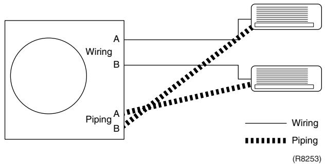
4. Trial Operation
4.1 RA Indoor Unit - FTXG, FTXS, CTXS, FVXG, FVXS, FLXS, FDXS Series
Outline
- Measure the power supply voltage and make sure that it falls in the specified range.
- Trial operation should be carried out in either cooling or heating operation.
- Carry out the trial operation in accordance with the operation manual to ensure that all functions and parts, such as flap movement, are working properly.
The air conditioner requires a small amount of power in its standby mode. If the system is not to be used for some time after installation, shut off the circuit breaker to eliminate unnecessary power consumption.
If the circuit breaker trips to shut off the power to the air conditioner, the system backs up the operation mode. The system then restarts operation with the previous operation mode when the circuit breaker is restored.
In cooling operation, select the lowest programmable temperature; in heating operation, select the highest programmable temperature.
■ Trial operation may be disabled in either operation mode depending on the room temperature.
After trial operation is complete, set the temperature to a normal level. (26^ 28^ in cooling, 20^ 24^ in heating)
For protection, the system does not start for 3 minutes after it is turned off.
Detail
ARC466 Series
(1) Press the [On/Off] button to turn on the system.
(2) Press the center of the [Temp] button and the [Mode] button at the same time.
(3) Select ?^ (trial operation) with the [Temp] or button.
(4) Press the [Mode] button to start the trial operation.
(5) Press the [Mode] button and select operation mode.
(6) Trial operation terminates in approx. 30 minutes and switches into normal mode. To quit a trial operation, press the [On/Off] button.

ARC452 Series
(1) Press the [ON/OFF] button to turn on the system.
(2) Press the both of [TEMP] buttons and the [MODE] button at the same time.
(3) Press the [MODE] button twice.
(7" appears on the display to indicate that trial operation is selected.)
(4) Press the [MODE] button and select the operation mode.
(5) Trial operation terminates in approx. 30 minutes and switches into normal mode. To quit a trial operation, press the [ON/OFF] button.

ARC433 Series
(1) Press the [ON/OFF] button to turn on the system.
(2) Press the center of the [TEMP] button and the [MODE] button at the same time.
(3) Press the [MODE] button twice.
(7" appears on the display to indicate that trial operation is selected.)
(4) Press the [MODE] button and select the operation mode.
(5) Trial operation terminates in approx. 30 minutes and switches into normal mode. To quit a trial operation, press the [ON/OFF] button.

4.2 SA Indoor Unit - FCQG, FFQ, FHQ, FDBQ, FBQ Series
4.2.1 Check points
To carry out test operation, check the followings:
- Check that the temperature setting of the remote controller is at the lowest level in cooling mode.
- Go through the following checklist:
| Checkpoints | Cautions or warnings |
| Are all units securely installed? | Dangerous for turning over during stormPossible damage to pipe connections |
| Is the earth wire installed according to the applicable local standard? | Dangerous if electric leakage occurs. |
| Are all air inlets and outlets of the indoor and outdoor units unobstructed? | Poor coolingPoor heating |
| Does the drain flow out smoothly? | Water leakage |
| Is piping adequately heat-insulated? | Water leakage |
| Have the connections been checked for refrigerant leakage? | Poor coolingPoor heatingStop |
| Is the supply voltage conform to the specifications on the name plate? | Incorrect operation |
| Are the cable sizes as specified and according to local regulations? | Damage of cables |
| Are the remote controller signals received by the unit? | No operation |
4.2.2 Test operation
BRC1D528
| Step | Action |
| 1 | Turn on the power supply more than 6 hours before test operation. |
| 2 | Open the gas stop valve. |
| 3 | Open the liquid stop valve. |
| 4 | Set to cooling operation with the remote controller and start operation by pressing [ON/OFF] button ( ☐). |
| 5 | Press the [INSPECTION/TEST OPERATION] button ( ☐) 4 times (2 times for wireless remote controller) and operate at test operation mode for 3 minutes. |
| 6 | Press the [AIRFLOW DIRECTION ADJUST] button ( ☐) to make sure the unit is in operation. |
| 7 | Press the [INSPECTION/TEST OPERATION] button ( ☐) and operate normally. |
| 8 | Confirm all the function of unit according to the operation manual. |
| 9 | If the decoration panel has not been installed, turn off the power after the test operation. |
BRC1E51A7
| Step | Action | Remote controller |
| Before test operation |
| 1 | Turn on the power supply more than 6 hours before test operation. | |
| 2 | Open the gas stop valve. | |
| 3 | Open the liquid stop valve. | |
| How to activate test operation |
| 4 | Press and hold the [Cancel] button ( ) for 4 seconds to enter the Field setting menu. | |
| 5 | Use the▼▲ buttons to select Test operation ON/OFF and push the [Menu/Enter] button ( ). | Field setting 1/2
Test operation ON/OFF
Register Service Contract
Field setting list
Group No, setting
Indoor unit Airnet No, set
Outdoor unit Airnet No, set
Return Setting
(R12872) |
| 6 | Test operation is displayed on the bottom of the basic screen. | Cool
Test Operation
(R12873) |
| 7 | Push the [ON/OFF] button ( ) within 10 seconds to start the test operation. | |
| How to check airflow direction |
| 8 | Push the [Menu/Enter] button ( ) to enter the Main Menu. | |
| 9 | Use the▼▲ buttons to select Airflow direction and push the [Menu/Enter] button ( ). | MainMenu 1/2
Set temp mode changeover
Airflow Direction
Quick Cool/Heat On/Off
Ventilation
Timer setting
Service Contact/Model Info
Return Setting
(R12874) |
| 10 | Check that the airflow direction is actuated according to the setting and push the [Menu/Enter] button ( ). | Airflow Direction
Swing
Return Setting
(R12875) |
| How to deactivate test operation |
| 11 | Press and hold the [Cancel] button ( ) for 4 seconds to enter the Field setting menu. | |
| 12 | Use the▼▲ buttons to select Test operation ON/OFF in the menu and push the [Menu/Enter] button ( ). | Field setting 1/2
Test operation ON/OFF
Register Service Contract
Field setting list
Group No, setting
Indoor unit Airnet No, set
Outdoor unit Airnet No, set
Return Setting
(R12876) |
5. Field Settings
5.1 Outdoor Unit
5.1.1 Priority Room Setting
Outdoor electronic expansion valves are controlled to provide more capacity to the prioritized room.
Setting method
Turn off the circuit breaker before changing the setting.
Only one room can be set as the priority room (By turning on one of the SW4 on the service monitor PCB of the outdoor unit).
The control starts when all the following conditions are met.
- Priority room setting is made.
- "POWERFUL" signal from the priority room unit is received.
Note: The operation mode of the priority room unit has precedence.
Cancellation of control
The control function is canceled when the "POWERFUL" operation mode is switched off or 20 minutes elapse after "POWERFUL Operation" started.

The prioritized room will be heated/cooled much more quickly
(R1396)

5.1.2 COOL/HEAT Mode Lock
Use the [S15] connector to set the unit to cooling only or heating only.
Setting to heating only (H): Short-circuit pins 1 and 3 of the connector [S15].
Setting to cooling only (C): Short-circuit pins 3 and 5 of the connector [S15].
The following specifications apply to the connector housing and pins.
JST products Housing: VHR-5N
Pin: SVH-21T-1, 1
Note that forced operation is also possible in cooling / heating mode.
- The illustration is for 68/75/80/90 models as representative. On 40/50/52/58 models, the location of the [S15] connector is slightly different.

Arrow view A


(R14567)
5.1.3 NIGHT QUIET Mode
If NIGHT QUIET mode is to be used, initial settings must be made when the unit is installed. Explain the function of NIGHT QUIET mode, as described below, to the customer, and confirm whether or not the customer wants to use NIGHT QUIET mode.
NIGHT QUIET mode function reduces operating noise of the outdoor unit at nighttime. This function is useful if the customer is worried about the effects of the operating noise on the neighbors. However, if NIGHT QUIET mode is running, cooling capacity is reduced.
Procedure
- Remove the SW5 jumper switch on the service monitor PCB of the outdoor unit. Once the settings are complete, reset the power.

Service monitor PCB
- Install the removed jumper switch as described below. This jumper switch is needed later to disable this setting.

Jumper switch

After removing
(R10813)
5.1.4 ECONO-mode-proof Setting
Outline
When installing in hotels, you can make ECONO mode ineffective on the outdoor unit.
Operation
The ECONO mode can be switched over between "effective" and "ineffective" by pressing the forced operation [ON/OFF] switch (SW1) on the outdoor unit and wiring error check switch (SW3) on the outdoor unit at the same time and holding them for 5 seconds while the compressor is stopped. The LEDs are lit in turn for 15 seconds to show the ECONO mode status.
The factory setting is "effective".
| LED flashing order | effective → ineffective | ineffective → effective |
| 3 or 4-room model | 4 → 3 → 2 → 1 | 1 → 2 → 3 → 4 |
| 5-room model | 5 → 4 → 3 → 2 → 1 | 1 → 2 → 3 → 4 → 5 |
5.2 RA Indoor Unit - FTXG, FTXS, CTXS, FVXG, FVXS, FLXS, FDXS Series
5.2.1 Model Type Setting
ARC452A1, ARC452A3, ARC466A6
- The remote controller is common to the heat pump model and cooling only model. Use the DIP switch on the remote controller to set the model type.
Set the DIP switch as shown in the illustration. (The factory set is the heat pump side.)
- Heat pump model: Set the DIP switch to H/P.
- Cooling only model: Set the DIP switch to C/O.

5.2.2 When 2 Units are Installed in 1 Room
Outline
When 2 indoor units are installed in 1 room, 1 of the 2 indoor units and the corresponding wireless remote controller can be set for different address.
Both the indoor unit PCB and the wireless remote controller need alteration.
The method of address setting varies depending on the type of indoor unit and the series of wired remote controller. Refer to the following pages for the appropriate indoor unit and wireless remote controller.
Wall Mounted Type
(1) Remove the front grille.
(2) Remove the electrical box.
(3) Remove the shield plate of the electrical box.
(4) Cut the address setting jumper JA on the PCB.

FTXG Series
(Bottom of electrical box)
FTXS-K, CTXS-K Series

(R12036)
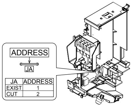
FTXS-J Series
(R12216)

FTXS-G Series
(R11735)
Floor Standing Type
FVXG Series
(1) Remove the front panel, air filters and front grille.
(2) Remove the screw, and remove the service cover.

(R14629)
(3)Turn on the DIP switch [S2W-1] on the service PCB.

(R14630)
- Keep the other switches as factory setting (OFF).
FVXS Series
1) Remove the front grille.
2) Lift the sensor PCB fixing plate and remove the front shield plate.
3) Disconnect the connectors [S1] [S41] [S42].
4) Remove the electric box (1 screw).
5) Pull out the indoor heat exchanger thermistor.
6) Remove the shield plate (8 tabs).
7) Cut the address setting jumper JA on the indoor unit PCB.

4) Remove the screw.

(R17290)
Floor / Ceiling Suspended Dual Type
Cut the jumper JA on PCB.

Duct Connected Type
Cut the jumper JA on PCB.

(R10276)
Wireless Remote Controller
(1) Remove the cover and take it off.
(2) Cut the address setting jumper.

ARC466 series

ARC452 series

ARC433 series
5.2.3 Jumper and Switch Settings
| Jumper (on indoor unit PCB) | Function | When connected (factory set) | When cut |
| JB | Fan speed setting when compressor stops for thermostat OFF. (effective only at cooling operation) | Fan speed setting; Remote controller setting | Fan speed setting; “0” (The fan stops.) |
| JC | Power failure recovery function | Auto_restart | The unit does not resume operation after recovering from a power failure. Timer settings are cleared. |
| Switch (on indoor unit PCB) | Function | OFF (factory set) | ON |
| SW2-4 | Upward airflow limit setting | Exposed or half embedded installation | Set the switch to ON position when you install the indoor unit embedded in the wall to avoid condensation. |
| Switch (on indoor unit PCB) | Function | FLOOR (factory set) | CEILING |
| SW2 | Installation style changeover | When installed as the floor mounted type | When installed as the ceiling suspended type |

For the location of the jumper and the switch, refer to the following pages.
Wall Mounted Type: page 42, 45, 47, 50
Floor Standing Type: page 53, 56
Floor / Ceiling Suspended Dual Type: page 58
Duct Connected Type: page 60
5.3 SA Indoor Unit - FCQG, FFQ, FHQ, FDBQ, FBQ Series
5.3.1 How to Change the Field Settings
Outline
If optional accessories are mounted on the indoor unit, the indoor unit setting may have to be changed. Refer to the instruction manual for each optional accessory.
Wired remote controller

BRC1D528
To set the field settings, you have to change:
Mode No.
First code No.
Second code No.
| Step | Action |
| 1 | Press the [INSPECTION/TEST OPERATION] button for 4 seconds during normal mode to enter the field setting mode. |
| 2 | Press the [TEMPERATURE ADJUST] button to select the desired mode No. |
| 3 | ■ If the indoor unit is under group control, all settings for all the indoor units are set at the same time. Use the codes 10 to 15 to apply this group control and proceed to the next step.
■ If you want to set the indoor units of one group individually or if you want to read out the last settings, use the codes 20 to 25 which are displayed in brackets. Press the [PROGRAMMING] button to select the indoor unit No. for which you want to adjust the field settings. |
| 4 | Press the upper part of the [TIME ADJUST] button to select the first code No. |
| 5 | Press the lower part of the [TIME ADJUST] button to select the second code No. |
| 6 | Press the [SCHEDULE TIMER] button to confirm the setting. |
| 7 | Press the [INSPECTION/TEST OPERATION] button to return to normal mode. |

BRC1E52A7, BRC1E52B7
a Unit No.
b First code No.
c Second code No.
d Mode
| Step | Action | Remote controller |
| 1 | Press and hold the [Cancel] button ( ) for 4 seconds to enter the Field setting menu. | |
| 2 | Use the ▼▲ buttons to select Field setting list and push the [Menu/Enter] button ( ) | Field setting 1/2
Test operation ON/OFF
Register Service Contract
Field setting list
Group No. setting
Indoor unit Airnet No. set
Outdoor unit Airnet No. set
Return Setting
(R12879) |
| 3 | Use the ▼▲ buttons to select the desired Mode. | |
| 4 | During group control, when setting by each indoor unit (Mode 20, 21, 22 and 23 have been selected), push the ▲ button to highlight and ▼▲ buttons to select the INDOOR UNIT NO. to be set. This operation is unnecessary when setting by group. | |
| 5 | Highlight the second code No. to be changed using the ▲▲ buttons, and use the ▼▲ buttons to select the desired second code No. | When setting by group, all of the second code No. that may be set are displayed as “*”. |
| 6 | Push the [Menu/Enter] button ( ) to display the confirmation screen. | |
| 7 | Use the ▲▲ buttons to select Yes and push the [Menu/Enter] button ( ) | When multiple setting changes are needed, repeat steps 3 to 7. |
| 8 | Push the [Cancel] button ( ) 2 times to return to basic screen. | |
5.3.2 Overview of the Field Settings
| Mode No. | First Code No. | Description of setting | Second Code No. |
| 01 | 02 | 03 |
| 10(20) | 0 | Filter cleaning sign interval | Ultra longlife filter | Light | Approx. 10,000 hrs. | Heavy | Approx. 5,000 hrs. | — |
| Longlife filter | Approx. 2,500 hrs. | Approx. 1,250 hrs. |
| 1 | Longlife filter type | Longlife filter | Ultra longlife filter | — |
| 2 | Remote controller thermistor | Enabled | Disabled | — |
| 3 | Filter cleaning sign | Display | No display | — |
| 11(21) | 0 | Indoor unit number of simultaneous operation system | Pair | Twin | Triple |
| 1 | Simultaneous operation system individual setting | Unified setting | Individual setting | — |
| 7 | External static pressure setting | Airflow adjustment is OFF | Completion of airflow adjustment | Start of airflow adjustment |
| 12(22) | 1 | Forced ON/OFF function | Forced OFF | ON/OFF operation | — |
| 2 | Thermostat differential changeover (setting for when using remote sensor) | 1°C | 0.5°C | — |
| 13(23) | 0 | High air outlet velocity (for high ceiling applications) | ≤2.7 m | 2.7 ~ 3.0 m | 3.0 ~ 3.5 m |
| 1 | Selection of airflow direction (setting for when a blocking pad kit has been installed) | 4-way flow | 3-way flow | 2-way flow |
| 3 | Selection of airflow function (setting for when using a decoration panel for outlet) | Equipped | Not equipped | — |
| 4 | Airflow direction range setting | Upper | Normal | Lower |
| 6 | External static pressure | Refer to Note 2. |
| 14(24) | 2 | Dust collection sign interval | Approx. 1,250 hrs. | Approx. 2,500 hrs. | Approx. 5,000 hrs. |
| 3 | Filter replacement sign | No display | Approx. 32,000 hrs. | Approx. 48,000 hrs. |
| 4 | Panel indicator (green) ON/OFF | The indicator lights up during both air conditioning operation and filter auto-cleaning. | The indicator can light up only during filter auto-cleaning. | The indicator does not light up during both air conditioning operation and filter auto-cleaning. |
| 8 | Selection of the automatic control operation lock mode | ON | OFF | — |
| 9 | Dust amount setting | Standard | Heavy | — |
| 15(25) | 3 | Drain pump operation with humidifying | Not equipped | Equipped | — |
: factory set

Note: 1. Any function that is not available on the indoor unit is not displayed.
| External static pressure (Pa) |
| Mode No. | First code No. | Second code No. | FBQ |
| 35 class | 50 class | 60 class |
| 13 (23) | 6 | 03 | 30 | 30 | 30 |
| 04 | 35 | 35 | 40 |
| 05 | 40 | 40 | 50 |
| 06 | 45 | 45 | 60 |
| 07 | 50 | 50 | 70 |
| 08 | 60 | 60 | 80 |
| 09 | 70 | 70 | 90 |
| 10 | 80 | 80 | 100 |
| 11 | 90 | 90 | - |
| 12 | 100 | 100 | - |
: factory set
5.3.3 MAIN / SUB Setting when Using 2 Wired Remote Controllers
Outline
The MAIN / SUB setting is necessary when 1 indoor unit is controlled by 2 remote controllers. When you use 2 remote controllers (control panel and separate remote controller), set one to MAIN and the other to SUB.
Detail
The remote controllers are factory set to MAIN, so you only have to change one remote controller from MAIN to SUB.
BRC1D528
| Step | Action |
| 1 | Insert a flat screwdriver into the groove between the upper and lower part of the remote controller, as shown in the illustration below. Gently pry off the upper part of the controller, working from the two possible positions.
Upper part of the remote controller
Lower part of the remote controller
(R11738) |
| 2 | Set the [MAIN / SUB changeover] switch on the PCB to “S”.
The switch is set to
MAIN (factory setting)
↓
M
S
Set the switch to SUB.
(R11739) |
BRC1E52A7, BRC1E52B7
| Step | Action | Remote controller |
| 1 | Put on the power for both remote controllers. | |
| 2 | Determine which one is the sub/main remote controller. | |
| 3 | When Error code: U5 - Connection under check Please wait for a moment is displayed on both remote controllers, push and hold the [Operation mode selector] button of the sub remote controller for 4 seconds. | Error code:U5
Connection under check
Please wait for a moment
Main remote contrl
(R12880) |
| 4 | The sub remote controller now displays Sub remote contrl.
Note) The main remote controller still displays Main remote contrl. | Connection under check
Please wait for a moment
Sub remote contrl
(R12881) |
| 5 | After a few seconds, the basic screen is displayed. | |
6. Application of Silicon Grease to a Power Transistor and a Diode Bridge
Applicable Models
All outdoor units using inverter type compressor for room air conditioner.
When the printed circuit board (PCB) of an outdoor unit is replaced, it is required that silicon grease (*1) is certainly applied to the heat radiation part (the contact point to the radiation fin) of the power transistor and diode bridge.
*1: Parts number of the silicon grease - 1172698 (Drawing number 3FB03758-1)
Details
The silicon grease is an essential article for encouraging the heat radiation of the power transistor and the diode bridge. Applying the paste should be implemented in accordance with the following instruction.
Note: There is the possibility of failure with smoke in case of bad heat radiation.
Wipe off the old silicon grease completely on a radiation fin.
Apply the silicon grease evenly to the whole.
- Do not leave any foreign object such as solder or paper waste between the power transistor and the radiation fin, and also the diode bridge, and the radiation fin.
- Tighten the screws of the power transistor and the diode bridge, and contact to the radiation fin without any gap.
The shape of electrical box and PCB vary depending on the model.


OK: Evenly applied silicon grease.

(R9056)
Part 9
Appendix
- Piping Diagrams 425
1.1 Outdoor Unit 425
1.2 Indoor Unit 430
- Wiring Diagrams 437
2.1 Outdoor Unit 437
2.2 Indoor Unit 442
1. Piping Diagrams
1.1 Outdoor Unit
1.1.1 Cooling Only
3MKS50E3V1B

3D052056C
4MKS58E3V1B

3D052057B
4MKS75F2V1B

5MKS90E2V3B

3D051938
1.1.2 Heat Pump
3MXS40K2V1B

3D073394
3MXS52E3V1B

3D052055D
3MXS68G2V1B

3D058888
4MXS68F2V1B

3D055041
4MXS80E2V3B
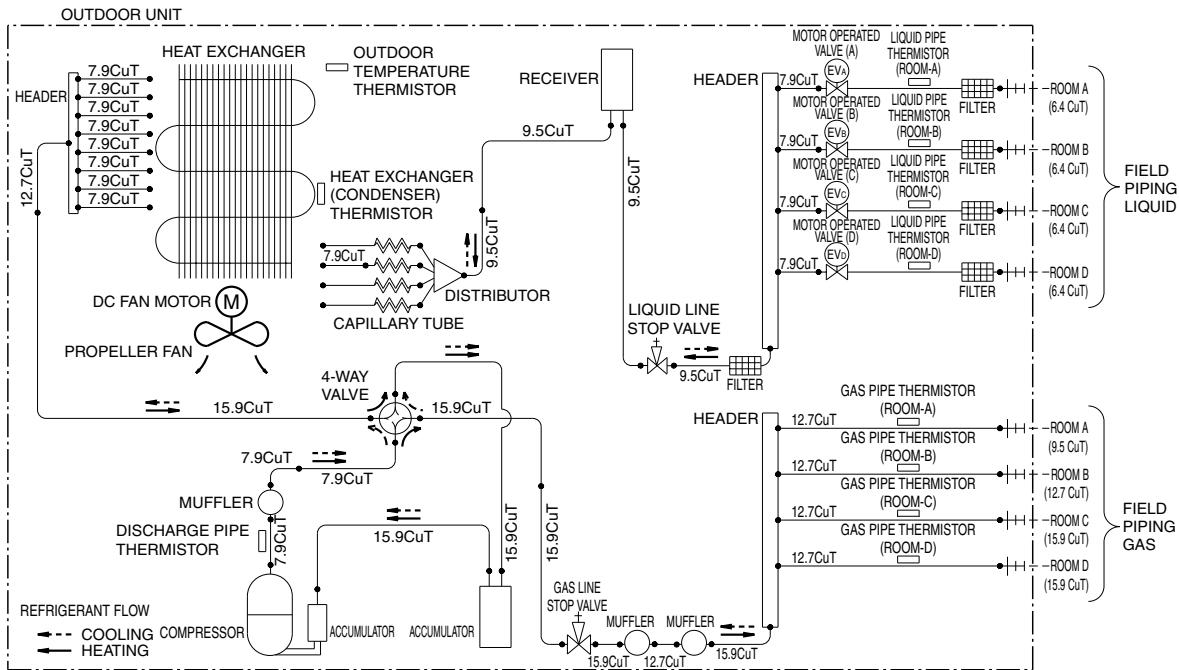
3D051937E
5MXS90E2V3B

3D051936A
1.2 Indoor Unit
1.2.1 Wall Mounted Type
FTXG25/35JV1BW(A)
FTXG50JV1BW(A)


4D065855B
4D065856C
FTXS20/25K2V1B, CTXS15/35K2V1B
FTXS25/35/42J2V1B


4D058926N
4D058897H
FTXS50J2V1B

BEEBIGERANT FLOW
COOLING
HEATING
4D058898F
FTXS60GV1B

REFRIGERANT
COOLING
HEATING
4D040081Y
1.2.2 Floor Standing Type
FVXG25/35K2V1B
FVXG50K2V1B


4D071597
4D071598
FVXS25/35FV1B
FVXS50FV1B

REFRIGERANT FLOW COOLING HEATING

REFRIGERANT FLOW COOLING HEATING
4D056137B
4D056138C
1.2.3 Floor / Ceiling Suspended Dual Type
FLXS25/35BAVMB
FLXS50/60BAVMB


4D048722B
4D048724B
1.2.4 Duct Connected Type
FDXS25/35E7VMB, FDXS50/60C7VMB

| A | | A |
| FDXS25E7VMB | 9.5 | FDXS50C7VMB | 12.7 |
| FDXS35E7VMB | FDXS60C7VMB |
C:4D045449Q
1.2.5 Ceiling Mounted Cassette Type
FCQG35/50/60FVEB
REFRIGERANT FLOW
COOLING
HEATING - - -

C:4D076993
FFQ25/35/50/60B9V1B

| MODEL | A | B |
| FFQ25/35B9V1B | 6.4 | 9.5 |
| FFQ50/60B9V1B | 6.4 | 12.7 |
C:4D039335B
1.2.6 Ceiling Suspended Type
FHQ35/50/60BWW1B

| MODEL | A | B |
| FHQ35BWV1B | 6.4 | 9.5 |
| FHQ50, 60BWV1B | 6.4 | 12.7 |
C:4D037995L
1.2.7 Ceiling Mounted Built-in Type
FDBQ25B8V1

Refrigerant flow
Cooling
Heating


Refrigerant pipe connection port diameters
| Model | Gas | Liquid |
| FDBQ25B8V1 | φ9.52 | φ6.35 |
C:3TW20815-1B
FBQ35/50/60C8VEB

Refrigerant flow
Cooling
Heating- - →
Refrigerant pipe connection port diameters
| Model | Gas | Liquid |
| FBQ35C | 9.52 | 6.35 |
| FBQ50C | 12.70 | 6.35 |
| FBQ60C | 12.70 | 6.35 |
C:3TW31275-1
2. Wiring Diagrams
2.1 Outdoor Unit
2.1.1 Cooling Only

3MKS50E3V1B
| Z1C-Z4C | : FERRITE CORE | MRM10, MMR20 | | L | : LIVE | M1C | : COMPRESSOR MOTOR |
| X1M-X4M | : TERMINAL STRIP | MRC/W | : MAGNETIC RELAY | N | : NEUTRAL | M1F | : FAN MOTOR |
| Y1E-Y3E | : ELECTRONIC EXPANSION VALVE COIL | R1T-R6T | | SW1 | : FORCED OPERATION ON/OFF SW (SW1) | L1R | : REACTOR |
| V2, V3, V5, V6, V11 | : VARISTOR | R8T-R10T | : THERMISTOR | SW2 | : SELECT SW (SW2) | Q1L | : OVERLOAD PROTECTOR |
| SA2 | : SURGE ARRESTER | S2-S102 | : CONNECTOR | SW3 | : WIRING ERROR CHECK SW (SW3) | PM1 | : POWER MODULE |
| FU1, FU2, FU3 | : FUSE | LED1-LED4 | | SW4 | : PRIORITY ROOM SETTING SW (SW4) | PCB1, 2 | : PRINTED CIRCUIT BOARD |
| AC1, AC2 | | LEDA | : PILOT LAMP | SW5 | : NIGHT QUIET MODE SETTING SW (SW5) | SHEET METAL | : TERMINAL STRIP FIXED PLATE |
| U, V, W, X11A | | | | | | | |
| E1, E2 | | | | | | | |
| HR1, HR2 | : CONNECTOR | | | | | | |

4MKS58E3V1B

4MKS75F2V1B

ZHC-ZBC XYM-XSM YYE-YAE
V2,V3,V5,V9,V100 SA2
E2 E11E12
AC1,AC2
U、V、W、X11A
E1,E2
HR1, HR2
FERRITE CORE TERMINAL STRIP
VARISTOR
SURGE ARRESTER
:FUSE
: CONNECTOR
MRM10,MRM20
MRC/W
MRCW/
1-1T
S2~S102
LED1-LED4
LEDA
PILOT LAMP
L :LIVI
N:NEUTRAL SW1:FORCEDOPERATIONON/OFFSW(SW1)
SW2:SELECT SW2W2
SW3 : WIRING ERROR CHECK SW (SW3)
SW4 : PRIORITY ROOM SETTING SW (SW4)
SW5 :NIGHT QUIET MODE SETTING SW (SW5)
M1C M1F
MIP L1B
ETH Q1L
PM1
PCB1,2
SHEET METAL:TERM
RESSOR MOTOR MOTOR
TOR
OR LOAD PROTECTOR
R MODULE
ED CIRCUIT BOARD
3D055885

5MKS90E2V3B
2TW27596-1A
2.1.2 Heat Pump

3MXS40K2V1B, 3MXS52E3V1B

3MXS68G2V1B

4MXS68F2V1B

4MXS80E2V3B
2TW27576-1B

5MXS90E2V3B
2TW27586-1A
2.2 Indoor Unit
2.2.1 Wall Mounted Type
FTXG25/35/50JV1BW(A)
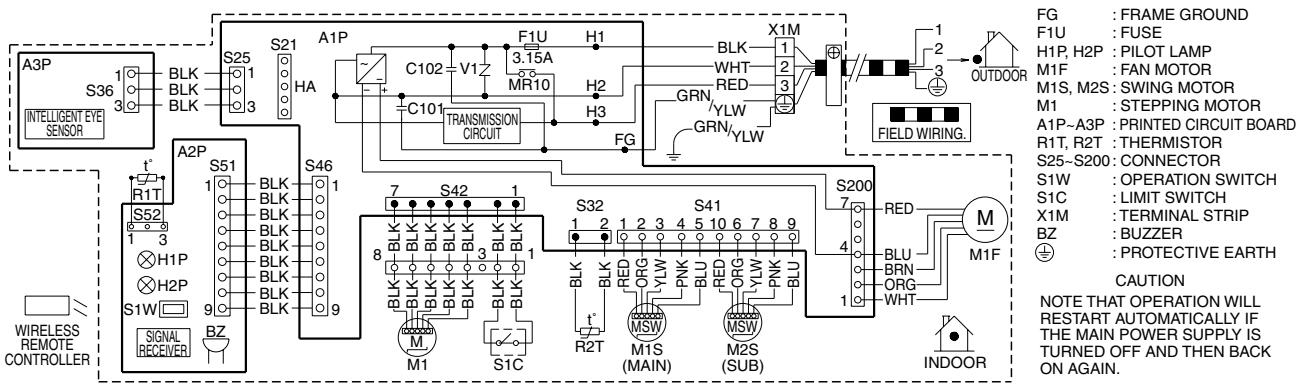
3D065507D
FTXS20/25K2V1B, CTXS15/35K2V1B

3D073474C
FTXS25/35/42/50J2V1B

3D058246F
FTXS60/71GV1B

3D064800C
2.2.2 Floor Standing Type

FVXG25/35/50K2V1B
FVXS25/35/50FV1B

3D055953A
2.2.3 Floor / Ceiling Suspended Dual Type
FLXS25/35/50/60BAVMB

3D033909F
2.2.4 Duct Connected Type
FDXS25/35E7VMB, FDXS50/60C7VMB

3D045012M
2.2.5 Ceiling Mounted Cassette Type
FCQG35/50/60FVEB

NOTES 1. TERMINAL BLOCK 00 . CONNECTOR FIEI:FIELD WIRING
2. IN CASE USING CENTRAL REMOTE CONTROLLER, CONNECT IT TO THE UNIT IN ACCORDANCE WITH THE ATTACHED INSTALLATION MANUAL.
3. X2A, X8A, X33A, X35A, X36A ARE CONNECTED WHEN THE OPTIONAL ACCESSORIES ARE BEING USED. IN CASE OF USING AN AUTO CLEAN PANEL, SEE THE WIRING DIAGRAM OF IT.
4. CONNECT POWER OF ADAPTOR FOR WIRING TO TERMINAL BLOCK (X2M) OF INDOOR UNIT DIRECTLY.
5. IN CASE OF MAIN/SUB OVERCHANGE, SEE THE INSTALLATION MANUAL ATTACHED TO REMOTE CONTROLLER.
6. SYMBOLS SHOWS AS FOLLOWS:RED:RED BLK:BLACK WHT:WHITE YLW:YELLOW GRN:GREEN ORG:ORANGE BRN:BROWN PNK:PINK GRY:GRAY BLU:BLUE
7. SHOWS ONLY IN CASE OF PROTECTED PIPES. USE H07RN-F IN CASE OF NO PROTECTION.
8. FOR THE DETAIL, SEE WIRING DIAGRAM ATTACHED TO OUTDOOR UNIT.
9. WHEN CONNECTING THE INPUT WIRES FROM OUTSIDE, FORCED OFF OR ON/OFF CONTROL OPERATION CAN BE SELECTED BY THE REMOTE CONTROLLER. SEE INSTALLATION MANUAL FOR MORE DETAILS.

| INDOOR UNIT | RECEIVER/DISPLAY UNIT (ATTACHED TO WIRELESS REMOTE CONTROLLER) | CONNECTOR FOR OPTIONAL PARTS |
| A1P | PRINTED CIRCUIT BOARD | X2A | CONNECTOR (SENSOR KIT) |
| A2P | PRINTED CIRCUIT BOARD |
| A3P | PRINTED CIRCUIT BOARD (HUMIDITY SENSOR UNIT) | A4P | PRINTED CIRCUIT BOARD | X8A | CONNECTOR (AUTO CLEAN PANEL) |
| C21 | CAPACITOR | A5P | PUSH BUTTON (ON/OFF) | X24A | CONNECTOR (WIRELESS REMOTE CONTROLLER) |
| C105 | CAPACITOR | BS1 | LIGHT EMITTING DIODE (ON-RED) |
| F1U | FUSE (F, 5A, 250V) | H1P | X33A | CONNECTOR (ADAPTOR FOR WIRING) |
| HAP | LIGHT EMITTING DIODE (SERVICE MONITOR GREEN) | H2P | LIGHT EMITTING DIODE (TIMER-GREEN) | X35A | CONNECTOR (GROUP CONTROL ADAPTOR) |
| M1F | MOTOR (INDOOR FAN) | H3P | LIGHT EMITTING DIODE (FILTER SIGN-RED) | X36A | CONNECTOR (AUTO CLEAN PANEL) |
| M1P | MOTOR (DRAIN PUMP) | H4P | LIGHT EMITTING DIODE (DEFROST-ORANGE) | | |
| M1S-M4S | MOTOR (SWING FLAP) | | |
| R1T | THERMISTOR (AIR) | SS1 | SELECTOR SWITCH (MAIN/SUB) | | |
| R2T-R3T | THERMISTOR (COIL) | | |
| S1L | FLOAT SWITCH | SS2 | SELECTOR SWITCH (WIRELESS ADDRESS SET) | | |
| SS1 | SELECTOR SWITCH (EMERGENCY) | | |
| V1R | DIODE BRIDGE | ADAPTOR FOR WIRING | | |
| X1M | TERMINAL BLOCK | F1U | FUSE (⑧, 5A, 250V) | | |
| X2M | TERMINAL BLOCK | F2U | | |
| Z1C | FERRITE CORE (NOISE FILTER) | KCR | MAGNETIC RELAY | | |
| KFR | MAGNETIC RELAY | | |
| (Z1F) | NOISE FILTER | KHur | MAGNETIC RELAY (Hu) | | |
| (PS) | POWER SUPPLY CIRCUIT | | | | |
| (RC) | SIGNAL RECEIVER CIRCUIT | | | | |
| (TC) | SIGNAL TRANSMISSION CIRCUIT | | | | |
| WIRED REMOTE CONTROLLER | | | | |
| R1T | THERMISTOR (AIR) | | | | |
3D074344
FFQ25/35/50/60B9V1B

NOTES:
- IN CASE OF USING A REMOTE CONTROLLER, CONNECT IT TO THE UNIT IN ACCORDANCE TO THE ATTACHED INSTALLATION MANUAL.
- X24A IS CONNECTED WHEN THE WIRELESS REMOTE CONTROLLER KIT IS BEING USED.
- REMOTE CONTROLLER MODEL VARIOUS ACCORDING TO THE COMBINATION SYSTEM.
SEE TECHNICAL DATA AND CATALOGS, ETC. BEFORE CONNECTING.
(IN CASE OF USING SHIELD WIRE)
| A1P | PRINTED CIRCUIT BOARD | Wired Remote CONTROLLER | WIRELESS REMOTE CONTROLLER
(RECEIVER/DISPLAY UNIT) | CONNECTOR FOR OPTIONAL PARTS |
| C1 | CAPACITOR (M1F) | R1T | THERMISTOR (AIR) | X33A | CONNECTOR
(ADAPTOR FOR WIRING) |
| F1U | FUSE (F5A, 250V) | SS1 | SELECTOR SWITCH (MAIN/SUB) | A3P | PRINTED CIRCUIT BOARD |
| HAP | LIGHT EMITTING DIODE
(Service MONITOR GREEN) | | | A4P | PRINTED CIRCUIT BOARD |
| | BS1 | PUSH BUTTON(ON/OFF) | X35A |
| KPR | MAGNETIC RELAY (M1P) | | | H1P | LIGHT EMITTING DIODE
(ON-RED) | X40A |
| M1F | MOTOR (INDOOR FAN) | | | CONNECTOR
(ON/OFF INPUT FROM OUTSIDE) |
| M1P | MOTOR (DRAIN PUMP) | | | H2P | LIGHT EMITTING DIODE
(TIMER-GREEN) | X60A |
| M1S | MOTOR (SWING FLAP) | | | CONNECTOR
(INTERFACE ADAPTOR FOR SKY-AIR SERIES) |
| Q1M | THERMO SWITCH
(M1F EMBEDDED) | | | H3P | LIGHT EMITTING DIODE
(FILTER SIGN-RED) | |
| R1T | THERMISTOR (AIR) | | | H4P | LIGHT EMITTING DIODE
(DEFROST-ORANGE) | |
| R2T | THERMISTOR (COIL-1) | | | SS1 | SELECTOR SWITCH
(MAIN/SUB) | |
| R3T | THERMISTOR (COIL-2) | | | |
| S1L | FLOAT SWITCH | | | SS2 | SELECTOR SWITCH
(WIRELESS ADDRESS SET) | |
| T1R | TRANSFORMER (220-240V/22V) | | | | | |
| V1TR | PHASE CONTROL CIRCUIT | | | | | |
| X1M | TERMINAL STRIP | | | | | |
| X2M | TERMINAL STRIP | | | | | |
| RC | SIGNAL RECEIVER CIRCUIT | | | | | |
| TC | SIGNAL TRANSMISSION CIRCUIT | | | | | |
:TERMINAL
:CONNECTOR
WIRECLAMP
FIELD WIRING
RED: RED
BLK:BLACK
WHT:WHITE
YLW: YELLOW
GRN: GREEN
3TW26476-1
2.2.6 Ceiling Suspended Type
FHQ35/50/60BWV1B

3D074574A
2.2.7 Ceiling Mounted Built-in Type
FDBQ25B8V1

| A1P | PRINTED CIRCUIT BOARD | R1T | THERMISTOR (AIR) | ADAPTOR FOR WIRING | FIELD SUPPLY |
| T1R | POWER SUPPLY TRANSFORMER (TRANSFORMER 220-240V/218V) | R2T | THERMISTOR (LIQUID) | RyH | MAGNETIC RELAY | K1R | MAGNETIC RELAY |
| R3T | THERMISTOR (COIL) | Q1L | THERMAL PROTECTOR | EH | ELECTRICAL HEATER KIT |
| C1R | CAPACITOR (FAN) | RyF1-4 | MAGNETIC RELAY (FAN) | CONNECTOR FOR OPTIONAL PARTS | | |
| F1U | FUSE (5A, 250V) | SS1 | SELECTOR SWITCH (EMERGENCY) | X60A, X61A | CONNECTOR (INTERFACE ADAPTOR FOR SKY AIR/US SERIES) | | |
| F1T | THERMAL FUSE (152°C) (M1F EMBEDDED) | X1M | TERMINAL STRIP | | |
| X2M | TERMINAL STRIP | X33A | CONNECTOR (ADAPTOR FOR WIRING) | | |
| HAP | LIGHT EMITTING DIODE (SERVICE MONITOR-GREEN) | RC | SIGNAL RECEIVER CIRCUIT | X35A | CONNECTOR (GROUP CONTROL ADAPTOR) | | |
| TC | SIGNAL TRANSMISSION CIRCUIT | X40A | CONNECTOR (REMOTE ON/OFF FORCED OFF) | | |
| M1F | MOTOR (FAN) | | | | | | |
2TW25856-1B

FBQ35/50C8VEB

FBQ60C8VEB
- Daikin products are manufactured for export to numerous countries throughout the world. Prior to purchase, please confirm with your local authorised importer, distributor and/or retailer whether this product conforms to the applicable standards, and is suitable for use, in the region where the product will be used. This statement does not purport to exclude, restrict or modify the application of any local legislation.
- Ask a qualified installer or contractor to install this product. Do not try to install the product yourself. Improper installation can result in water or refrigerant leakage, electrical shock, fire or explosion.
- Use only those parts and accessories supplied or specified by Daikin. Ask a qualified installer or contractor to install those parts and accessories. Use of unauthorised parts and accessories or improper installation of parts and accessories can result in water or refrigerant leakage, electrical shock, fire or explosion.
- Read the User's Manual carefully before using this product. The User's Manual provides important safety instructions and warnings. Be sure to follow these instructions and warnings.
If you have any enquiries, please contact your local importer, distributor and/or retailer.
Cautions on product corrosion
- Air conditioners should not be installed in areas where corrosive gases, such as acid gas or alkaline gas, are produced.
- If the outdoor unit is to be installed close to the sea shore, direct exposure to the sea breeze should be avoided. If you need to install the outdoor unit close to the sea shore, contact your local distributor.
Dealer
DAIKIN INDUSTRIES, LTD.
Head Office:
Umeda Center Bldg., 2-4-12, Nakazaki-Nishi,
Kita-ku, Osaka, 530-8323 Japan
Tokyo Office:
JR Shinagawa East Bldg., 2-18-1, Konan,
Minato-ku, Tokyo, 108-0075 Japan
http://www.daikin.com/global_ac/
©All rights reserved