
FTXB-C - FTXB20C + RXB20C - FTXB25C + RXB25C - Air-conditioner DAIKIN - Free user manual and instructions
Find the device manual for free FTXB-C - FTXB20C + RXB20C - FTXB25C + RXB25C DAIKIN in PDF.
Download the instructions for your Air-conditioner in PDF format for free! Find your manual FTXB-C - FTXB20C + RXB20C - FTXB25C + RXB25C - DAIKIN and take your electronic device back in hand. On this page are published all the documents necessary for the use of your device. FTXB-C - FTXB20C + RXB20C - FTXB25C + RXB25C by DAIKIN.
USER MANUAL FTXB-C - FTXB20C + RXB20C - FTXB25C + RXB25C DAIKIN
CE - DECLARATION-OF-CONFORMITY
- Agent frigorific: <N>
- Setting of pressure safety device: <P> (bar)
- Manufacturing number and manufacturing year: refer to model nameplate 02 • Maximal zulässiger Druck (PS): <K> (Bar)
- Minimal/maximal zulässige Temperatur (TS*):
CE - DECLARATION-OF-CONFORMITY
CE - DECLARATION-DE-CONFORMITE
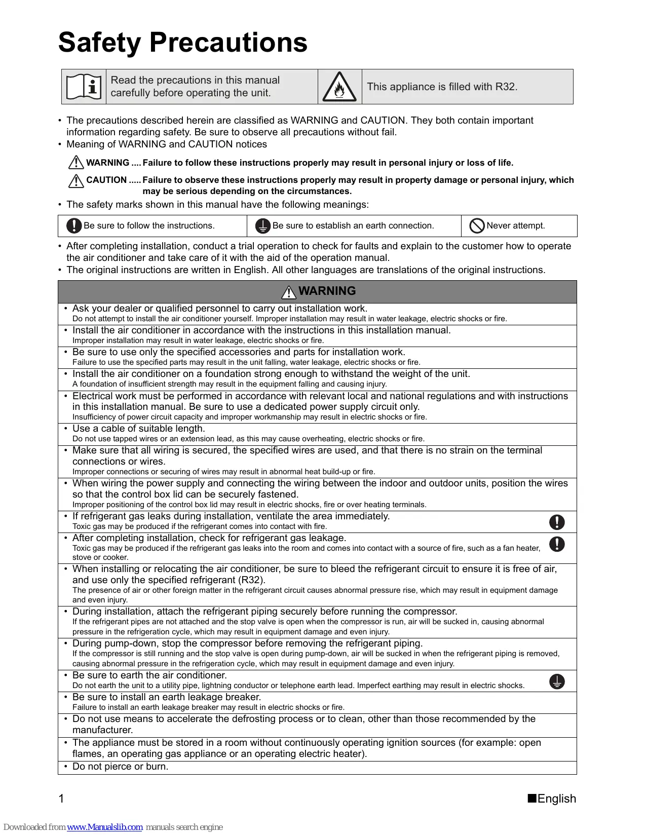
2P427092-2D Safety Precautions Read the precautions in this manual carefully before operating the unit. This appliance is filled with R32.
- The precautions described herein are classified as WARNING and CAUTION. They both contain important information regarding safety. Be sure to observe all precautions without fail.
- Meaning of WARNING and CAUTION notices WARNING .... Failure to follow these instructions properly may result in personal injury or loss of life. CAUTION ..... Failure to observe these instructions properly may result in property damage or personal injury, which may be serious depending on the circumstances.
- The safety marks shown in this manual have the following meanings: Be sure to follow the instructions. Be sure to establish an earth connection. Never attempt.
- After completing installation, conduct a trial operation to check for faults and explain to the customer how to operate the air conditioner and take care of it with the aid of the operation manual.
- The original instructions are written in English. All other languages are translations of the original instructions. WARNING
- Ask your dealer or qualified personnel to carry out installation work. Do not attempt to install the air conditioner yourself. Improper installation may result in water leakage, electric shocks or fire.
- Install the air conditioner in accordance with the instructions in this installation manual. Improper installation may result in water leakage, electric shocks or fire.
- Be sure to use only the specified accessories and parts for installation work. Failure to use the specified parts may result in the unit falling, water leakage, electric shocks or fire.
- Install the air conditioner on a foundation strong enough to withstand the weight of the unit. A foundation of insufficient strength may result in the equipment falling and causing injury.
- Electrical work must be performed in accordance with relevant local and national regulations and with instructions in this installation manual. Be sure to use a dedicated power supply circuit only. Insufficiency of power circuit capacity and improper workmanship may result in electric shocks or fire.
- Use a cable of suitable length. Do not use tapped wires or an extension lead, as this may cause overheating, electric shocks or fire.
- Make sure that all wiring is secured, the specified wires are used, and that there is no strain on the terminal connections or wires. Improper connections or securing of wires may result in abnormal heat build-up or fire.
- When wiring the power supply and connecting the wiring between the indoor and outdoor units, position the wires so that the control box lid can be securely fastened. Improper positioning of the control box lid may result in electric shocks, fire or over heating terminals.
- If refrigerant gas leaks during installation, ventilate the area immediately. Toxic gas may be produced if the refrigerant comes into contact with fire.
- After completing installation, check for refrigerant gas leakage. Toxic gas may be produced if the refrigerant gas leaks into the room and comes into contact with a source of fire, such as a fan heater, stove or cooker.
- When installing or relocating the air conditioner, be sure to bleed the refrigerant circuit to ensure it is free of air, and use only the specified refrigerant (R32). The presence of air or other foreign matter in the refrigerant circuit causes abnormal pressure rise, which may result in equipment damage and even injury.
- During installation, attach the refrigerant piping securely before running the compressor. If the refrigerant pipes are not attached and the stop valve is open when the compressor is run, air will be sucked in, causing abnormal pressure in the refrigeration cycle, which may result in equipment damage and even injury.
- During pump-down, stop the compressor before removing the refrigerant piping. If the compressor is still running and the stop valve is open during pump-down, air will be sucked in when the refrigerant piping is removed, causing abnormal pressure in the refrigeration cycle, which may result in equipment damage and even injury.
- Be sure to earth the air conditioner. Do not earth the unit to a utility pipe, lightning conductor or telephone earth lead. Imperfect earthing may result in electric shocks.
- Be sure to install an earth leakage breaker. Failure to install an earth leakage breaker may result in electric shocks or fire.
- Do not use means to accelerate the defrosting process or to clean, other than those recommended by the manufacturer.
- The appliance must be stored in a room without continuously operating ignition sources (for example: open flames, an operating gas appliance or an operating electric heater).
- Do not pierce or burn.
Downloaded from www.Manualslib.com manuals search engine English
- Be aware that refrigerants may not contain an odour.
- This appliance must be installed, operated and stored in a room larger than the minimum required floor area.
- Comply with national gas regulations. Safety Precautions CAUTION
- Do not install the air conditioner at any place where there is a danger of flammable gas leakage. In the event of a gas leakage, build-up of gas near the air conditioner may cause a fire to break out.
- While following the instructions in this installation manual, install drain piping to ensure proper drainage and insulate piping to prevent condensation. Improper drain piping may result in indoor water leakage and property damage.
- Tighten the flare nut according to the specified method such as with a torque wrench. If the flare nut is too tight, it may crack after prolonged use, causing refrigerant leakage.
- Make sure to provide for adequate measures in order to prevent that the outdoor unit be used as a shelter by small animals. Small animals making contact with electrical parts can cause malfunctions, smoke or fire. Please instruct the customer to keep the area around the unit clean.
- The temperature of refrigerant circuit will be high, please keep the inter-unit wire away from copper pipes that are not thermally insulated.
- This appliance is intended to be used by expert or trained users in shops, in light industry and on farms, or for commercial and household use by lay persons.
- Sound pressure level is less than 70 dB(A).
- The following information shall be provided at an accessible place of the system: -instructions for shutting down the system in case of an emergency -name and address of fire department, police and hospital -name, address and day & night telephone numbers for obtaining service. In Europe, EN378 provides the necessary guidance for this logbook. Accessories Accessories supplied with the outdoor unit: A Installation Manual + R32 Manual
B Drain plug C Reducer assembly
It is on the bottom of the packing case. It is on the bottom of the packing case. E Refrigerant charge label R32 D Screw bag (For fixing electrical wire anchor bands)
It is on the bottom of the packing case. F Multilingual fluorinated greenhouse gases label G Drain cap (1)
It is on the bottom of the packing case. English Downloaded from www.Manualslib.com manuals search engine
Precautions for Selecting the Location 1) Choose a place solid enough to bear the weight and vibration of the unit, where the operation noise will not be amplified. 2) Choose a location where the hot air discharged from the unit or the operation noise will not cause a nuisance to the neighbours of the user.
3) Avoid places near a bedroom and the like, so that the operation noise will cause no trouble.
4) There must be sufficient spaces for carrying the unit into and out of the site.
5) There must be sufficient space for air passage and no obstructions around the air inlet and the air outlet.
6) The site must be free from the possibility of flammable gas leakage in a nearby place.
7) Install units, power cords and inter-unit wire at least 3m away from television and radio sets. This is to prevent interference to images and sounds. (Noises may be heard even if they are more than 3m away depending on radio wave conditions.) 8) In coastal areas or other places with salty atmosphere of sulfate gas, corrosion may shorten the life of the air conditioner. 9) Since water will flow from the drain of the outdoor unit, do not place under the unit anything which must be kept away from moisture. NOTE Cannot be installed hanging from ceiling or stacked. CAUTION When operating the air conditioner in a low outdoor ambient temperature, be sure to follow the instructions described below.
- To prevent exposure to wind, install the outdoor unit with its suction side facing the wall.
- Never install the outdoor unit at a site where the suction side may be exposed directly to wind.
- To prevent exposure to wind, it is recommended to install a baffle plate on the air discharge side of the outdoor unit.
- In heavy snowfall areas, select an installation site where the snow will not affect the unit.
Downloaded from www.Manualslib.com manuals search engine ● Construct a large canopy ● Construct a pedestal Install the unit high enough off the ground to prevent burying in snow. English Indoor/Outdoor Unit Installation Drawings For installation of the indoor units, refer to the installation manual which was provided with the units. (The diagram shows a wall-mounted indoor unit.) CAUTION
- Do not connect the embedded branch piping and the outdoor unit when only carrying out piping work without connecting the indoor unit in order to add another indoor unit later. Make sure no dirt or moisture gets into either side of the embedded branch piping. See “7 Refrigerant piping work” on page 9 for details.
- It is impossible to connect the indoor unit for one room only. Be sure to connect at least 2 rooms. The flare connection should be installed outdoors. Cut thermal insulation pipe to an appropriate length and wrap it with tape, making sure that no gap is left in the insulation pipe’s cut line. Max. allowable refrigerant charge amount 3MXM40M 2.2kg
2.2kg 3MXM68M 2.4kg 4MXM68M 2.6kg 4MXM80M 3.0kg 5MXM90M 3.3kg Caulk pipe hole gap with putty. Wrap the insulation pipe with the finishing tape from bottom to top. Allow 300mm of work space below the ceiling surface. Refrigerant piping must be protected from physical damage. Install a plastic cover or equivalent. Refrigerant piping must be kept to a minimum. Minimum floor area for installation 3MXM40M 250mm from 4.7m2
4.7m2 3MXM68M 5.5m2 4MXM68M 6.5m2 4MXM80M 8.6m2 5MXM90M 10.4m2 Allow space for piping and electrical servicing. Stop valve cover
If there is the danger of the unit falling or overturning, fix the unit with foundation bolts, or with wire or other means.
(Foot bo lthole cen tres) Level mounting base (optional parts) If the location does not have good drainage, place the unit on a level mounting base (or a plastic pedestal). Install the outdoor unit in a level position. Failure to do so may result in water leakage or accumulation. English Downloaded from www.Manualslib.com manuals search engine wall ole
ltbo ) ot res (F ent
unit: mm Also insulate the connection on the outdoor unit. Clamping material Insulation tube Tape Service lid Use tape or insulating material on all connections to prevent air from getting in between the copper piping and the insulation tube. Be sure to do this if the outdoor unit is installed above.
- Install the unit horizontally.
- The unit may be installed directly on a concrete verandah or a solid place if drainage is good.
- If the vibration may possibly be transmitted to the building, use a vibration-proof rubber (field supply).
Connections (connection port) Install the indoor unit according to the table below, which shows the relationship between the class of indoor unit and the corresponding port. The total indoor unit class that can be connected to this unit: Heat pump type: 3MXM40M* - Up to 7.0kW 4MXM68M* - Up to 11.0kW 3MXM52M* - Up to 9.0kW 4MXM80M* - Up to 14.0kW 3AMXM52M* - Up to 9.0kW 5MXM90M* - Up to 15.5kW 3MXM68M* - Up to 11.0kW : Use a reducer to connect pipes. : Use No. 2 and 4 reducers. : Use No. 5 and 6 reducers. : Use No. 1 and 3 reducers. Refer to “How to Use Reducers” on page 10 for information on reducer numbers and their shapes. Precautions on Installation
- Check the strength and level of the installation ground so that the unit will not cause any operating vibration or noise after installed.
- In accordance with the foundation drawing in fix the unit securely by means of the foundation bolts. (Prepare 4 sets of M8 or M10 foundation bolts, nuts and washers each which are available on the market.)
- It is best to screw in the foundation bolts until their ends are 20mm from the foundation surface.
Downloaded from www.Manualslib.com manuals search engine English Outdoor Unit Installation Guideline
- Where a wall or other obstacle is in the path of outdoor unit’s inlet or outlet airflow, follow the installation guidelines below.
- For any of the below installation patterns, the wall height on the exhaust side should be 1200mm or less. Walls facing two sides Wall facing one side More than 350 More than 100 Direction of air More More than 100 than 350
or less More than 50 More than 50 Top view Side view Walls facing three sides More than 100 More than 350 More than 50 unit: mm Top view Selecting a Location for Installation of the Indoor Units
- The maximum allowable length of refrigerant piping, and the maximum allowable height difference between the outdoor and indoor units, are listed below. (The shorter the refrigerant piping, the better the performance. Connect so that the piping is as short as possible. Shortest allowable length per room is 3m.) Outdoor unit capacity class 3MXM40M* 3MXM52M* 3AMXM52M* 3MXM68M* 4MXM68M* 4MXM80M* 5MXM90M* Piping to each indoor unit 25m max. 25m max. 25m max. 25m max. 25m max. 25m max. Total length of piping between all units 50m max. 50m max. 50m max. 60m max. 70m max. 75m max. Outdoor Unit Indoor Unit Level difference: 15m max. Level difference: 7.5m max. Level difference: 15m max. Outdoor Unit Level difference: 7.5m max. Indoor Unit If the outdoor unit is positioned higher than the indoor units. English Downloaded from www.Manualslib.com manuals search engine If the outdoor unit is positioned otherwise. (If lower than one or more indoor units)
Installing outdoor unit 1) When installing the outdoor unit, refer to “Precautions for Selecting the Location” on page 3 and the “Outdoor Unit Installation Drawings” on page 4.
2) If drain work is necessary, follow the procedures below.
Drain work G Drain cap (1) H Drain cap (2)
- If the drain port is covered by a mounting base or floor surface, place additional foot bases of at least 1-1/4 inch (30mm) in height under the outdoor unit’s feet.
- In cold areas, do not use a drain socket, drain caps (1,2) and a drain hose with the outdoor unit. (Otherwise, the drain water may freeze, impairing heating performance.)
1) Attach Ⓖ drain cap (1) and Ⓗ drain cap (2).
Use the flare nut fixed to the main unit. (To prevent cracking of the flare nut by aged deterioration.) To prevent gas leakage, apply refrigeration oil only to the inner surface of the flare. (Use refrigeration oil for R32.) Use torque wrenches when tightening the flare nuts to prevent damage to the flare nuts and gas leakage. Do not reuse joints which have been used once already. Installation shall be done by an installer, the choice of materials and installation shall comply with the applicable legislation. In Europe the EN378 is the applicable standard that shall be used.
- Ensure that the field piping and connections are not subjected to stress. Align the centres of both flares and tighten the flare nuts 3 or 4 turns by hand. Then tighten them fully with the torque wrenches. [Apply oil] [Tighten] Apply refrigeration oil to the inner surface of the flare. Do not apply refrigeration oil to the outer surface. Torque wrench Flare nut Spanner Piping union Flare nut Do not apply refrigeration oil to the flare nut to avoid tightening with excessive torque. Flare nut tightening torque ø 1/4 inch (6.4mm) 10-1/2 — 12-3/4ft ● lbf (14.2-17.2N ● m) ø 3/8 inch (9.5mm) 24-1/8 — 29-1/2ft ● lbf (32.7-39.9N ● m) ø 1/2 inch (12.7mm) 36-1/2 — 44-1/2ft ● lbf (49.5-60.3N ● m) ø 5/8 inch (15.9mm) 45-5/8 — 55-5/8ft ● lbf (61.8-75.4N ● m) Width across flats 11/16 inch (17mm) 3/4 inch (19mm) 7/8 inch (22mm) 11/16 inch (27mm) Valve cap tightening torque 10-1/2 — 12-5/8ft ● lbf (14.2-17.2N ● m) 12-5/8 — 15-3/8ft ● lbf (17.1-20.9N ● m) 16 — 20-1/4ft ● lbf (21.6-27.4N ● m) 35-3/8 — 44-1/8ft ● lbf (48-59.8N ● m) Service port cap tightening torque
Downloaded from www.Manualslib.com manuals search engine 8 — 10-7/8ft ● lbf (10.8-14.7N ● m) English Refrigerant Piping Work
Evacuating the air with a vacuum pump and checking for gas leakage WARNING
Do not mix any substance other than the specified refrigerant (R32) into the refrigeration cycle. When refrigerant gas leaks should occur, ventilate the room as soon and as much as possible. R32, as well as other refrigerants, should always be recovered and never be released directly into the environment. Use a vacuum pump for R32 or R410A exclusively. Using the same vacuum pump for different refrigerants may damage the vacuum pump or the unit. Use tools for R32 or R410A (such as the gauge manifold, charging hose, or vacuum pump adapter). During tests never pressurize the appliances with a pressure higher than the maximum allowable pressure (as indicated on the nameplate of the unit). If refrigerant gas leaks, ventilate the area immediately. Toxic gas may be produced if refrigerant gas comes into contact with fire. Never directly touch any accidental leaking refrigerant. This could result in severe wounds caused by frostbite.
- When piping work is completed, it is necessary to purge the air and check for gas leakage.
- If using additional refrigerant, perform air purging from the refrigerant pipes and indoor unit using a vacuum pump, then charge additional refrigerant.
- Use a hexagonal wrench (4mm) to operate the stop valve rod.
- All refrigerant pipe joints should be tightened with a torque wrench to the specified tightening torque.
1) Connect projection side of charging hose (which comes from gauge manifold) to gas stop valve’s service port.
2) Fully open gauge manifold’s low-pressure valve (Lo) and completely close its high-pressure valve (Hi).
(High-pressure valve subsequently requires no operation.)
3) Perform vacuum pumping and make sure that the compound pressure gauge reads –0.1MPa (–76cmHg).
Evacuation for at least 1 hour is recommended.
4) Close gauge manifold’s low-pressure valve (Lo) and stop vacuum pump.
(Keep this state for 4-5 minutes to make sure that the compound pressure gauge pointer does not swing back. If it does go back, this may indicate the presence of moisture or leaking from connecting parts. After inspecting all the connection and loosening then retightening the nuts, repeat steps 2-4.)
5) Remove covers from liquid stop valve and gas stop valve.
6) Turn the liquid stop valve’s rod 90 degrees counterclockwise with a hexagonal wrench to open valve.
Close it after 5 seconds, and check for gas leakage. Using soapy water, check for gas leakage from indoor unit’s flare and outdoor unit’s flare and valve rods. After the check is complete, wipe all soapy water off.
7) Disconnect charging hose from gas stop valve’s service port, then fully open liquid and gas stop valves.
(Do not attempt to turn valve rod beyond its stop.) 8) Tighten valve caps and service port caps for the liquid and gas stop valves with a torque wrench at the specified torques. See “3. Refrigerant piping” on page 7 for details. English Downloaded from www.Manualslib.com manuals search engine
Charging with refrigerant 1) If the total length of piping for all rooms exceeds the figure listed below, additionally charge with 20g of refrigerant (R32) for each additional meter of piping. 3MXM40M, 3MXM52M, 3AMXM52M, 3MXM68M, 4MXM68M, 4MXM80M, 5MXM90M Outdoor capacity class Total length of piping for all rooms 30m Important information regarding the refrigerant used This product contains fluorinated greenhouse gases covered by the Kyoto Protocol. Do not vent gases into the atmosphere. Refrigerant type: R32 GWP(1) value:
(1) GWP = global warming potential Please fill in with indelible ink, 1 the factory refrigerant charge of the product, 2 the additional refrigerant amount charged in the field and 1 + 2 the total refrigerant charge on the refrigerant charge label supplied with the product. The filled out label must be adhered in the proximity of the product charging port (e.g. onto the inside of the stop valve cover). R32
1 factory refrigerant charge of the product: see unit name plate
2 additional refrigerant amount charged in the field (Refer to the above information for the quantity of refrigerant replenishment.)
3 total refrigerant charge 4 Contains fluorinated greenhouse gases covered by the Kyoto Protocol
5 outdoor unit 6 refrigerant cylinder and manifold for charging NOTE: National implementation of EU regulation on certain fluorinated greenhouse gases may require to provide the appropriate official national language on the unit. Therefore an additional multilingual fluorinated greenhouse gases label is supplied with the unit. Sticking instructions are illustrated on the backside of that label. CAUTION Even though the stop valve is fully closed, the refrigerant may slowly leak out; do not leave the flare nut removed for a long period of time.
Downloaded from www.Manualslib.com manuals search engine English Refrigerant Piping Work
Refrigerant piping work Wall Be sure to place a cap. Cautions on pipe handling Rain If no flare cap is available, cover the flare mouth with tape to keep dirt or water out.
1) Protect the open end of the pipe against dust and moisture.
2) All pipe bends should be as gentle as possible. Use a pipe bender for
bending. Selection of copper and heat insulation materials When using commercial copper pipes and fittings, observe the following:
1) Insulation material: Polyethylene foam
Heat transfer rate: 0.041 to 0.052W/mK (0.035 to 0.045kcal/mh°C) Refrigerant gas pipe’s surface temperature reaches 110°C max. Choose heat insulation materials that will withstand this temperature.
2) Be sure to insulate both the gas and liquid piping and to provide insulation dimensions as below.
Inter-unit wires Gas pipe Gas pipe O.D.: 9.5mm, 12.7mm / Thickness: 0.8mm (C1220T-O) O.D.: 15.9mm / Thickness: 1.0mm (C1220T-O) Liquid pipe O.D.: 6.4mm / Thickness: 0.8mm (C1220T-O) Gas pipe insulation I.D.: 12-15mm, I.D.: 16-20mm / Thickness: 13mm min. Liquid pipe insulation I.D.: 8-10mm / Thickness: 10mm min. Minimum bend radius O.D.: 6.4mm, 9.5mm / 30mm or more O.D.: 12.7mm / 40mm or more O.D.: 15.9mm / 50mm or more Liquid pipe Gas pipe insulation Liquid pipe insulation Finishing tape Drain hose
4) Piping and other pressure containing parts shall comply with the applicable legislation and shall be suitable for refrigerant. Use phosphoric acid deoxidised seamless copper for refrigerant.
Flaring the pipe end
1) Cut the pipe end with a pipe cutter.
2) Remove burrs with the cut surface facing downward so that the chips do not enter the pipe.
3) Put the flare nut on the pipe.
5) Check that the flaring is properly made.
(Cut exactly at right angles.) Remove burrs Flaring Set exactly at the position shown below.
Flare tool for R32 Conventional flare tool Clutch-type Clutch-type (Rigid-type) Wing-nut type (Imperial-type) 0-0.5mm 1.0-1.5mm 1.5-2.0mm Check Flare’s inner surface must be flaw-free. The pipe end must be evenly flared in a perfect circle. Make sure that the flare nut is fitted. WARNING
Do not use mineral oil on flared part. Prevent mineral oil from getting into the system as this would reduce the lifetime of the units. Never use piping which has been used for previous installations. Only use parts which are delivered with the unit. Never install a dryer to this R32 unit in order to guarantee its lifetime. The drying material may dissolve and damage the system. Incomplete flaring may cause refrigerant gas leakage. English Downloaded from www.Manualslib.com manuals search engine
How to Use Reducers No.1 φ15.9
- φ9.5 Gasket (2) No.6 φ15.9
- φ9.5 Reduce and gasket Use the reducers supplied with the unit as described below.
1) Connecting a pipe of φ12.7 to a gas pipe connection port for φ15.9:
No. 1 Be sure to attach the gasket. Inter-unit piping No. 3 Flare nut (for φ15.9) Connection port of outdoor unit
2) Connecting a pipe of φ9.5 to a gas pipe connection port for φ15.9:
Flare nut (for φ9.5) No. 6 No. 5 Be sure to attach the gasket.
3) Connecting a pipe of φ9.5 to a gas pipe connection port for φ12.7:
No. 2 No. 4 Flare nut (for φ12.7) Be sure to attach the gasket.
- When using the reducer packing shown above, be careful not to overtighten the nut, or the smaller pipe may be damaged. (about 2/3 - 1 the normal torque)
- Apply a coat of refrigeration oil to the threaded connection port of the outdoor unit where the flare nut comes in.
- Use an appropriate wrench to avoid damaging the connection thread by overtightening the flare nut.
Downloaded from www.Manualslib.com manuals search engine Flare nut tightening torque Flare nut for φ9.5 32.7–39.9N·m (333–407kgf·cm) Flare nut for φ12.7 49.5–60.3N·m (505–615kgf·cm) Flare nut for φ15.9 61.8–75.4N·m (630–769kgf·cm) English Pump Down Operation In order to protect the environment, be sure to pump down when relocating or disposing of the unit.
1) Remove the valve cap from liquid stop valve and gas stop valve.
2) Carry out forced cooling operation.
3) After 5 to 10 minutes, close the liquid stop valve with a hexagonal
4) After 2 to 3 minutes, close the gas stop valve and stop forced cooling operation.
Close Hexagonal wrench Gas stop valve Liquid stop valve Valve caps
Switch off the power. Remove the Service lid (2 screws). Remove the service PC-board switch cover (1 screw). Switch SW5 and SW6 to off. Turn the operation mode switch (SW2) to COOL. Screw the service PC-board switch cover back on (1 screw)Switch the power on. Push the forced operation switch (SW1) above the service PC-board cover. ■Start forced colling operation. To stop forced operation, push the forced operation switch (SW1) again. WARNING Do not remove the switch cover unless the power has been turned off. (Risk of electric shock) Service PC-board S502
SW3 SW1 English Downloaded from www.Manualslib.com manuals search engine
- Do not use tapped wires, stranded wires, extension cords, or starburst connections, as they may cause overheating, electrical shock, or fire.
- Do not use locally purchased electrical parts inside the product. (Do not branch the power for the drain pump, etc., from the terminal block.) Doing so may cause electric shock or fire.
- Be sure to install an earth leakage breaker. (One that can handle higher harmonics.) (This unit uses an inverter, which means that an earth leakage breaker capable of handling harmonics must be used, in order to prevent malfunctioning of the earth leakage breaker itself.)
- Use an all-pole disconnection type breaker with at least 3mm between the contact point gaps.
- Do not connect the power wire to the indoor unit. Doing so may cause electric shock or fire. <Wiring procedure> Outdoor unit Room
1) Strip the insulation from the wire (3/4inch (20mm)).
2) Connect the connection wires between the indoor
and outdoor units so that the terminal numbers Room match. Tighten the terminal screws securely. We recommend a flathead screwdriver be used to tighten the screws.
3) Be sure to match the symbols for wiring and
4) Pull the wire lightly to make sure that it does not
5) Pass the wiring through the cutout on the bottom of
the protection plate and attach the protection plate.
6) After completing the work, reattach the service lid to its original position.
Equipment complying with EN/IEC 61000-3-12 EDVHGRQFXUUHQW measurement) Room A Power supply wire 3-core 2.5mm² or more H05RN Room
Be sure to use the dedicated circuits. Room
Safety breaker Earth leakage circuit breaker 50Hz 220-240V To room D To room C Inter-unit wire 4-core 1.5mm² or more H05RN To room B To room E Room B power supply Room
Shape the wires so that there is no lifting of the service hatch or other structural parts. Room
Room D Room E 8VHWKHVSHFL¿HGZLUHVDQG connect them securely.
Downloaded from www.Manualslib.com manuals search engine English Wiring CAUTION
Precautions to be taken for power supply wiring. When using stranded wires, make sure to use the round crimp-style terminal for connection to the power supply terminal Round crimp-style terminal Stranded wire Flat washer Screw Screw
Screw Round crimpstyle terminal Round crimp-style terminal Flat washer Flat washer Wrong Good Round crimpstyle terminal Arrow view A
When connecting the inter-unit wires to the terminal block using a single core wire, be sure to curl the end of the lead. Improper work may cause heat and fires. Strip wire end to this point. Excessive strip length may cause electric shock or current leakage. Good Good
- Make sure that the earth wire between the pull relief and terminal is longer than the other wires. Wrong Wrong 1-3
Stripping wire at terminal block Ground This air conditioner must be grounded. For grounding, follow all local, and state electrical codes. A<B Standby Electricity Saving 3MXM40M, 3MXM52M, 3AMX52M only The standby electricity saving function turns off power supply to the outdoor unit and sets the indoor unit into standby electricity saving mode, thus reducing the power consumption of the air conditioner. The standby electricity saving function works on the following indoor unit. For FTXM, FTXP, FTXJ type CAUTION
- The standby electricity saving function cannot be used for models other than the specified ones.
Procedure for turning on standby electricity saving function
1) Check that the main power supply is turned off. Turn it
off if it has not been turned off.
2) Remove the stop valve cover.
3) Disconnect the selective connector for standby
4) Turn on the main power supply.
Standby electricity saving function off. CAUTION Standby electricity saving function on. The standby electricity saving function is turned off before shipping.
- Before connecting or disconnecting the selective connector for standby electricity saving, make sure that the main power supply is turned off.
- The selective connector for standby electricity saving is required if an indoor unit other than the above applicable one is connected. English Downloaded from www.Manualslib.com manuals search engine
Priority Room Setting
- To use priority room setting, initial settings must be made when the unit is installed. Explain the priority room setting, as described below, to the customer, and confirm whether or not the customer wants to use priority room setting. Setting it in the guest and living rooms is convenient.
About the priority room setting function The indoor unit for which priority room setting is applied takes priority in the following cases. 1-1. Operation mode priority The operation mode of the indoor unit which is set for priority room setting takes priority. If the set indoor unit is operating, all other indoor units do not operate and enter standby mode, according to the operation mode of the set indoor unit. 1-2. Priority during high-power operation If the indoor unit which is set for priority room setting is operating at high power, the capabilities of other indoor units will be somewhat reduced. Power supply gives priority to the indoor unit which is set for priority room setting. 1-3. Quiet operation priority Setting the indoor unit to quiet operation will make the outdoor unit run quietly. Setting procedure Slide the switch to the ON side for the switch that corresponds to the piping connected to the indoor unit to be set. (In the figure below, it is room A.) Once the settings are complete, reset the power. Be sure to only set one room Service PC-board
Remove the switch cover
Downloaded from www.Manualslib.com manuals search engine English Night Quiet Mode Setting
- If Night Quiet Mode is to be used, initial settings must be made when the unit is installed. Explain Night Quiet Mode, as described below, to the customer, and confirm whether or not the customer wants to use Night Quiet Mode. About Night Quiet Mode The Night Quiet Mode function reduces operating noise of the outdoor unit at nighttime. This function is useful if the customer is worried about the effects of the operating noise on the neighbors. However, if Night Quiet Mode is running, cooling capacity will be saved. Service PC-board Setting procedure Turn the Night Quiet Mode switch (SW6-1) to on. HEAT Mode Lock <SW5-1>
- Use the HEAT Mode Lock switch (SW5-1) in the “ON” position.
- Use the S15 connector to set the unit to cool only. Setting to only cool (C) : short-circuit pins 3 and 5 of the connector <S15> The following specifications apply to the connector housing and pins. ST products Housing: VHR-5N Pin: SVH-21T-1,1 Note that forced operation is also possible in COOL mode. COOL mode (C)
English Downloaded from www.Manualslib.com manuals search engine
Trial Operation and Testing
- Before starting the test run, measure the voltage at the primary side of the safety breaker.
- Check that all liquid and gas stop valves are fully open.
- Check that piping and wiring all match. The wiring error check can be conveniently used for underground wiring and other wiring that cannot be directly checked.
- This product is capable of automatic correction of wiring error.
- Press the “wiring error check switch” on the outdoor unit service PCboard. However, the wiring error check switch will not function for 3 minutes after the safety breaker is turned on, or depending on the outside air conditions (See Note 2.). About 15–20 minutes after the switch is pressed, the errors in the connection wiring will be corrected. Service PC-board
The service monitor LEDs indicate whether or not correction is possible, as shown in the table below. For details about how to read the LED display, refer to the service manual.
If self-correction is not possible, check the indoor unit wiring and piping in the usual manner. LED
Wiring error check switch (SW3) Message All Flashing Automatic correction impossible Flashing One after another Automatic correction completed (One or more of LEDs 1 to 4 are ON) Abnormal stop [NOTE. 4] Wiring correct example Terminal block ∗ The figure at left shows branch wiring. From Room C to the “kitchen” From Room B From Room D From Room A to the “living room” to the “children’s room” to the “bedroom” Wiring error check LED lighting sequence after a wiring correction. Order of LED flashing: 2 ➝ 1 ➝ 3 ➝ 4 NOTE: 1) For two rooms, LED 3, 4 and 5 are not displayed, and for three rooms, LED 4 and 5 is not displayed, and for four rooms, LED 5 is not displayed.
2) If the outside air temperature is 5°C or less , the wiring error check function will not operate.
3) After wiring error check operation is completed, LED indication will continue until ordinary operation starts.
4) Follow the product diagnosis procedures. (Details of product error diagnosis are listed on the back of the right side
Downloaded from www.Manualslib.com manuals search engine English Trial Operation and Testing
Trial operation and testing 1) To test cooling, set for the lowest temperature. To test heating, set for the highest temperature. (Depending on the room temperature, only heating or cooling (but not both) may be possible.)
2) After the unit is stopped, it will not start again (heating or cooling) for approximately 3 minutes.
3) When trial operation is conducted in the HEAT operation directly after the circuit breaker is turned on, in some cases no air will be output for about 15 minutes in order to protect the air conditioner. 4) During the test run, first check the operation of each unit individually. Then also check the simultaneous operation of all indoor units. Check both heating and cooling operation. 5) After running the unit for approximately 20 minutes, measure the temperatures at the indoor unit inlet and outlet. If the measurements are above the values shown in the table below, then they are normal. Temperature difference between inlet and outlet Cooling Heating Approx. 8°C Approx. 20°C (When running in one room)
6) During cooling operation, frost may form on the gas stop valve or other parts. This is normal.
7) Operate the indoor units in accordance with the included operation manual. Check that they operate normally.
Items to check Check item Consequences of trouble Are the indoor units installed securely? Falling, vibration, noise Has an inspection been made to check for gas leakage? Incomplete cooling/heating function Has complete thermal insulation been done (gas pipes, liquid pipes, indoor portions of the drain hose extension)? Water leakage Is the drainage secure? Water leakage Are the ground wire connections secure? Electrical leakage Are the electric wires connected correctly? Incomplete cooling/heating function Is the wiring in accordance with the specifications? No operation or burn damage Are the inlets/outlets of the indoor and outdoor units free of any obstructions? Incomplete cooling/heating function Are the stop valves open? Incomplete cooling/heating function Do the marks match (room A, room B, room C, room D, room E) on the wiring and piping for each indoor unit? Incomplete cooling/heating function Is the priority room setting set for 2 or more rooms? The priority room setting will not function. Check ATTENTION
- Have the customer actually operate the unit while looking at the manual included with the indoor unit. Instruct the customer how to operate the unit correctly (particularly cleaning of the air filters, operation procedures, and temperature adjustment).
- Even when the air conditioner is not operating, it consumes some electric power. If the customer is not going to use the unit soon after it is installed, turn off the breaker to avoid wasting electricity.
- If additional refrigerant has been charged because of long piping, list the amount added on the nameplate on the reverse side of the stop valve cover. English Downloaded from www.Manualslib.com manuals search engine
Piping Diagram Outdoor Unit Electronic expansion valve Heat exchanger Outdoor air temperature thermistor Thermistor (liquid) Refnet header 7.9CuT MVA 7.9CuT 7.9CuT Room A (6.4CuT) Heat exchanger thermistor 12.7CuT 7.9CuT Filter 6.4CuT 7.9CuT MVB 7.9CuT Muffler with filter 6.4CuT 9.5CuT 7.9CuT (6.4CuT) 9.5CuT Refnet header Field piping Liquid Room B Distributor MVC 7.9CuT 6.4CuT Room C 9.5CuT (6.4CuT) Capillary tube
Outdoor Unit Electronic expansion valve Heat exchanger Outdoor air temperature thermistor Thermistor (liquid) Refnet header 7.9CuT 7.9CuT 7.9CuT Heat exchanger thermistor 12.7CuT 7.9CuT MVB 7.9CuT 7.9CuT MVA Filter 6.4CuT Room A (6.4CuT) 6.4CuT 7.9CuT (6.4CuT) 9.5CuT Refnet header Distributor
PED categories of equipment - High pressure switches : category IV; Compressor : category II; Accumulator: category: I; Other art 3§3 equipment. NOTE: When the high pressure switch is activated it must be reset manually by a qualified person.
Downloaded from www.Manualslib.com manuals search engine English Piping Diagram Outdoor Unit Electronic expansion valve Heat exchanger Outdoor air temperature thermistor Thermistor (liquid) Refnet header 7.9CuT 7.9CuT 7.9CuT Heat exchanger thermistor 12.7CuT 7.9CuT MVB 7.9CuT 7.9CuT MVA Filter 6.4CuT Room A (6.4CuT) 6.4CuT 7.9CuT (6.4CuT) 9.5CuT Refnet header Distributor 7.9CuT
Capillary tube 7.9CuT
Outdoor Unit Electronic expansion valve Outdoor air temperature thermistor 7.9CuT Heat exchanger Thermistor (liquid) 7.9CuT 9.5CuT 7.9CuT 12.7CuT Heat exchanger 7.9CuT 7.9CuT 7.9CuT 7.9CuT Filter 6.4CuT Room A (6.4CuT) 6.4CuT Field piping Liquid Room B (6.4CuT) Capillary tube Liquid receiver 7.9CuT 9.5CuT 9.5CuT
7.9CuT Refnet header MVA MVB 7.9CuT Distributor 7.9CuT 7.9CuT 7.9CuT 9.5CuT 7.9CuT 7.9CuT 7.9CuT Liquid receiver 7.9CuT Heat exchanger thermistor Solenoid valve 6.4CuT MVC MVD 6.4CuT Room C (6.4CuT) 6.4CuT Room D (6.4CuT) 9.5CuT 9.5CuT
PED categories of equipment - High pressure switches : category IV; Compressor : category II; Accumulator: category: I; Other art 3§3 equipment. NOTE: When the high pressure switch is activated it must be reset manually by a qualified person. English Downloaded from www.Manualslib.com manuals search engine
Piping Diagram Outdoor Unit Electronic expansion valve Outdoor air temperature thermistor 7.9CuT Heat exchanger Thermistor (liquid) 7.9CuT 9.5CuT 7.9CuT 12.7CuT Heat exchanger 7.9CuT 7.9CuT 7.9CuT 7.9CuT Room A (6.4CuT) 6.4CuT Field piping Liquid (6.4CuT) Capillary tube Liquid receiver 7.9CuT 9.5CuT 9.5CuT
7.9CuT Heat exchanger thermistor Solenoid valve 6.4CuT Fan motor MVC MVD 6.4CuT Room C (6.4CuT) 6.4CuT Room D (6.4CuT) 9.5CuT 9.5CuT
PED categories of equipment - High pressure switches : category IV; Compressor : category II; Accumulator: category: I; Other art 3§3 equipment. NOTE: When the high pressure switch is activated it must be reset manually by a qualified person.