
REVOLUTION87 ERV750AWT-G 80PLUS GOLD - Computer power supply ENERMAX - Free user manual and instructions
Find the device manual for free REVOLUTION87 ERV750AWT-G 80PLUS GOLD ENERMAX in PDF.
User questions about REVOLUTION87 ERV750AWT-G 80PLUS GOLD ENERMAX
0 question about this device. Answer the ones you know or ask your own.
Ask a new question about this device
Download the instructions for your Computer power supply in PDF format for free! Find your manual REVOLUTION87 ERV750AWT-G 80PLUS GOLD - ENERMAX and take your electronic device back in hand. On this page are published all the documents necessary for the use of your device. REVOLUTION87 ERV750AWT-G 80PLUS GOLD by ENERMAX.
USER MANUAL REVOLUTION87 ERV750AWT-G 80PLUS GOLD ENERMAX
Only a technician, authorized by ENERMAX, is allowed to perform maintenance service! Warranty is subject to void under unauthorized attempt to open the power case or modification of any kinds, even attempted only, of the power supply or its components!
ENERMAX will not be responsible for damages caused by following situations:
- Opening of the PSU case and/or modification of any component or cable without ENERMAX's written authorization.
- Ignoring connector's wrong insertion prevention design by attaching a connector to a device in wrong orientation.
- Connecting too many devices to one cable unit by using additional adaptor (Y cables).
Usage of non-genuine ENERMAX modular cables.
The serial number label or warranty seal is defaced, modified, or removed. - Damage caused by natural phenomena or uncontrollable forces, such as lightning, flooding, fire, earthquake, etc.
This ENERMAX Technology Corporation product is warranted to be free from defects in material and workmanship for a period of five (5) years from the date of purchase. ENERMAX Technology Corporation agrees to repair or replace the product, at its own option and at no charge, if, during the warranty period, it is returned to nearest ENERMAX Technology Corporation subsidiary/agent with all shipping charges prepaid and bearing a return merchandise authorization (RMA) number, and if inspection reveals that the product is defective. Charges for removing or installing the product are excluded under the terms of this warranty agreement. This warranty shall not apply to any product, which has been subject to connection to a faulty power source, alteration, negligence, or accident, or to any product, which has been installed other than in accordance with these instructions. In no event shall ENERMAX Technology Corporation, or its subsidiaries, or agents be liable for damages for a breach of warranty in an amount exceeding the purchase price of this product!
If you are uncertain whether or not your ENERMAX PSU is defective, please contact your dealer/reseller for support!
Web Site: http://www.enermax.com
E-mail: enermax@enermax.com.tw
Forum: forum.enermax.com
ENERMAX Technology Corporation, 15F-2, No. 888, Jing-Guo Road, Taoyuan City (330), Taiwan (R.O.C.), Tel. +886-3-316-1675, Fax. +886-3-346-6640
©2011 ENERMAX Technology Corporation. All rights reserved. Specifications are subject to change without prior notice. Actual product and accessories may differ from illustrations. Omissions and printing errors excepted. Content of delivery might differ in different countries or areas. Some trademarks may be claimed as the property of others. Reproduction in any manner without the written permission of ENERMAX is strictly forbidden.
ENERMAX REVOLUTION87+ Series Power Supply Specification
| ERV550AWT-G | ERV650AWT-G | ERV750AWT-G | ERV850EWT-G | ERV1000EWT-G | ||||||
| AC Input Voltage | 100-240VAC, 50-60Hz | 115-240VAC, 50-60Hz | ||||||||
| AC Input Current | 7.5 - 3A | 8.5 - 3.5A | 9 - 4.5A | 11 - 5A | 11 - 5A | |||||
| DC OUTPUT | ||||||||||
| Rated | Combined | Rated | Combined | Rated | Combined | Rated | Combined | Rated | Combined | |
| 3.3V | 0-24A | 120W | 0-24A | 120W | 0-24A | 120W | 0-24A | 120W | 0-24A | 120W |
| 5V | 0-24A | 0-24A | 0-24A | 0-24A | 0-24A | |||||
| 12V1 | 0-25A | 540W (45A) | 0-25A | 648W (54A) | 0-25A | 744W (62A) | 0-30A | 840W (70A) | 0-30A | 996W (83A) |
| 12V2 | 0-25A | 0-25A | 0-25A | 0-30A | 0-30A | |||||
| 12V3 | 0-25A | 0-25A | 0-25A | 0-30A | 0-30A | |||||
| 12V4 | - | - | - | - | 0-25A | 0-30A | 0-30A | |||
| -12V | 0-0.5A | 6W | 0-0.5A | 6W | 0-0.5A | 6W | 0-0.5A | 6W | 0-0.5A | 6W |
| 5Vsb | 0-3A | 15W | 0-3A | 15W | 0-3A | 15W | 0-3A | 15W | 0-3A | 15W |
| Total Power | 550W | 650W | 750W | 850W | 1000W | |||||
| Peak Power* | 605W | 715W | 825W | 935W | 1100W | |||||
| PROTECTION CIRCUIT | ||||||||||
| Over Current Protection | DC Rail | OCP trigger range | ||||||||
| 3.3V | 30 - 40A | |||||||||
| 5V | 30 - 40A | |||||||||
| 12V | 30 - 40A (ERV550AWT-G / ERV650AWT-G) 35 - 45A (ERV750AWT-G / ERV850EWT-G / ERV1000EWT-G) | |||||||||
| Over Voltage Protection | DC Rail | OVP trigger range | ||||||||
| 3.3V | 3.7 - 4.1V | |||||||||
| 5V | 5.7 - 6.5V | |||||||||
| 12V | 13.1 - 14.5V | |||||||||
| (DC)Under Voltage Protection | DC Rail | UVP trigger range | ||||||||
| 3.3V | 2.0 - 2.4V | |||||||||
| 5V | 3.3 - 3.7V | |||||||||
| 12V | 8.5 - 9.5V | |||||||||
| Over Power Protection | Activated when output power > 120 ~ 150% of rated max load. | |||||||||
| Over Temperature Protection | Activated when PSU heat sink > 90 ~ 120°C. | |||||||||
| Short Circuit Protection | Activated when any DC rails short-circuited. | |||||||||
| ENVIRONMENT | ||||||||||
| Temperature | Operation ambient: 0~50°C (for full rated output) Storage: ambient: -40~70°C | |||||||||
| Humidity | Operation: to 85% relative humidity, non-condensing Storage: to 95% relative humidity, non-condensing | |||||||||
| OTHERS | ||||||||||
| Cooling | One 13.9cm twist bearing fan, speed auto controlled. | |||||||||
| MTBF | > 100,000 hours at 70% of full rated load, 230VAC/50Hz, 25°C (MIL-HDBK-217F standard) | |||||||||
| Dimension | 150(w) x 86(h) x 160(d) mm (ERV550AWT-G / ERV650AWT-G) 150(w) x 86(h) x 175(d) mm (ERV750AWT-G / ERV850EWT-G / ERV1000EWT-G) | |||||||||
| Weight | 2kg (without modular cables)±50g (ERV550AWT-G / ERV650AWT-G) 2.9kg(without modular cables)±50g (ERV750AWT-G / ERV850EWT-G / ERV1000EWT-G) | |||||||||
| Safety | UL/cUL(Level 6), TUV, GOST, CB, BSMI | |||||||||
| EMC | CE, FCC, KCC | |||||||||
- Peak power may last up to 60 seconds
User's Manual
Dear customer,
Thank you for choosing this ENERMAX power supply unit (PSU)! Please read this manual carefully and follow its instructions before installing the PSU.
We would like to draw your attention that a computer required very specific conditions to work best for you without failing. To avoid failures and to increase lifetime of the system, we suggest that:
- Your system is NOT located near a radiator or any other heat producing device
- Your system is NOT located near a magnetic device
- Your system is NOT located in a moist and/or dusty and/or vibrating environment
- Your system is NOT exposed to direct sunshine
- Your system is sufficiently cooled by additional fans
- If you use AC extension cables, please make sure it can support all connected appliances' potential peak power draw. Or redistribute other high power consumption equipment, such as laser printers or monitors to other AC wall outlets. Exceeding the extension cable's loading capacity could trigger its circuit breaker and cut off the power.
- If you want to add the UPS (Uninterruptible Power Supply) for your system, please choose adequate Watts/VA capacity UPS.
Ex.
| PSU Model | Suggested minimum UPS output power capacity (Based on efficiency & PFC at respective load) |
| ERV550AWT-G | 600W / 1000VA |
| ERV650AWT-G | 700W / 1100VA |
| ERV750AWT-G | 900W / 1400VA |
| ERV850EWT-G | 1000W / 1400VA |
| ERV1000EWT-G | 1100W / 1600VA |
- If you intend to add other appliance powered by the same UPS, such as monitor or printer, please use higher capacity UPS according to all connected devices' rated power draw.
- Please do not mistake VA capacity as Watts, or use insufficient power UPS. This would result in less UPS battery runtime or the inability to power the system in battery mode.
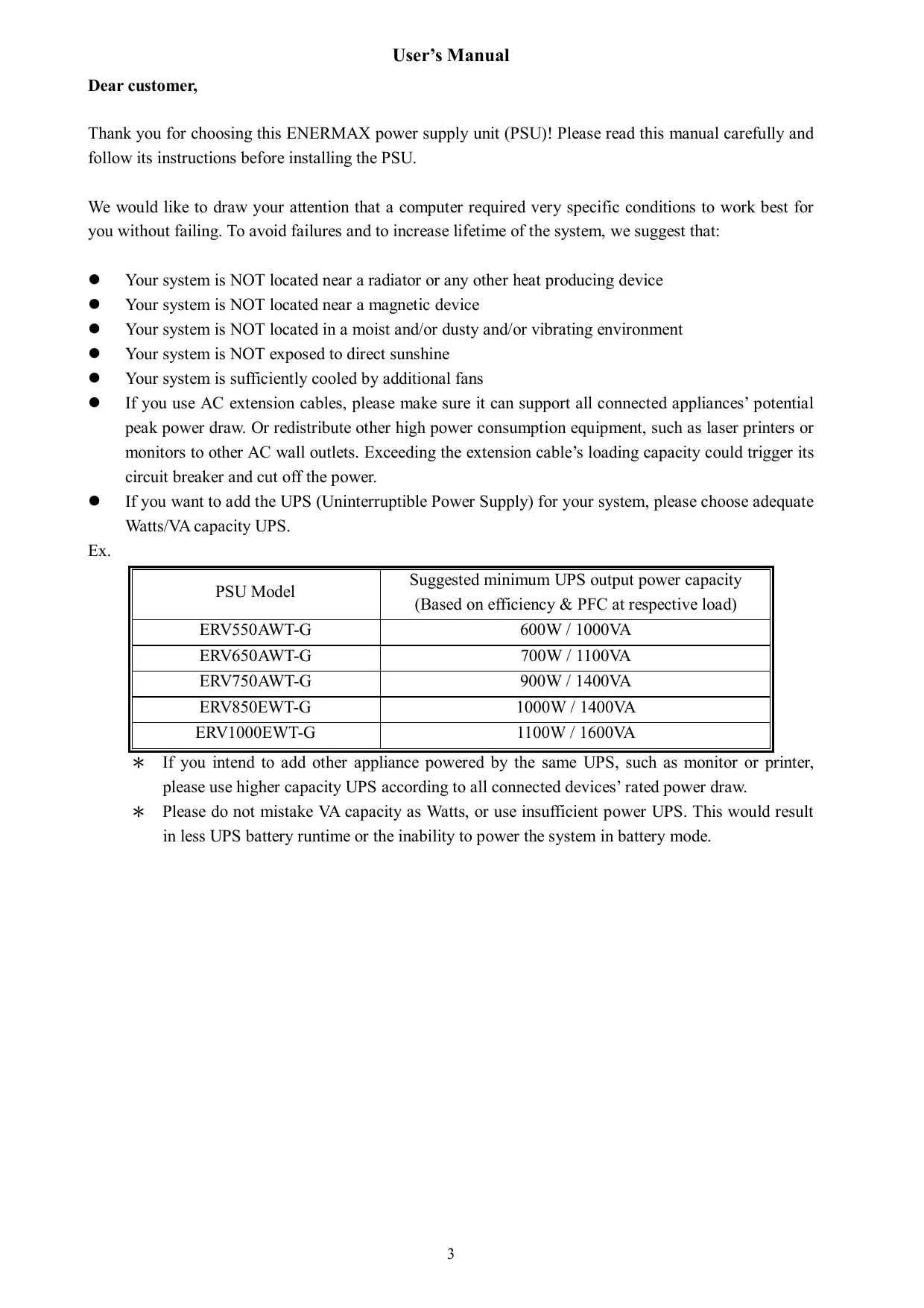
① Output cable: Please check "Cables & Connectors" section.
② Fan. #1
③ Honeycomb air vent.
④ ON/OFF switch (I=ON, O=OFF). #2
⑤ AC Inlet. #2
(6) CordGuard. #3
1 To ensure best system cooling, do not block PSU fan's air in-take and air vent area.
This PSU offers a special HeatGuard function. When the system is turned off, or goes into ACPI S3/S4 sleep mode, the PSU fan will keep dissipating the remaining heat for 30 60 seconds and prolonging system lifetime.
2 When assembling or maintaining the system, please remove AC cord from AC inlet, or turn ON/OFF switch into "OFF" position. Then you can safely service the system.
3 AC cord can get loose in many ways. The ENERMAX CordGuard lock can fix your AC cord tightly to the PSU, so that it will not be easily detached and avoid shut-downs of your PC. The following is CordGuard installation:
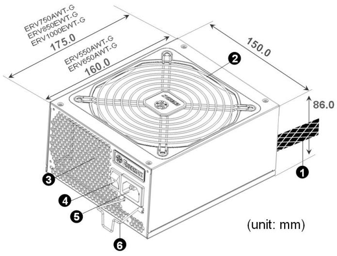
① Set your PSU into the chassis, and please make sure the I/O switch is on “O” position.
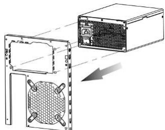
(2) Press two sides of the CordGuard lock together, and set it into
CordGuard holder near the AC inlet.
③ Plug the AC cord into your PSU.
④ Lock CordGuard to latch onto AC cord.
- CordGuard is for AC cords supplied with ENERMAX CordGuard-compatible PSUs. Other AC cords may be incompatible.
- When assembling or maintaining the system, please remove AC cord from AC inlet, or turn I/O switch into "O" position.
CABLES & CONNECTORS
All connectors are designed to prevent insertion in wrong orientation. If you cannot easily insert a connector, please check if you are inserting the connector in the right orientation. Do not try by force to insert it nor modify the connectors. This might damage power supply and system components, and warranty shall be void.
Following graphic illustrates the modular sockets layout and its DC rail distribution.
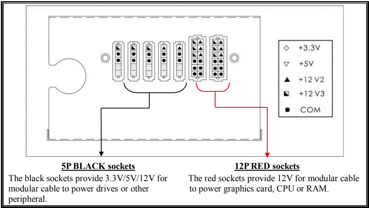
(ERV750AWT-G / ERV850EWT-G / ERV1000EWT-G)
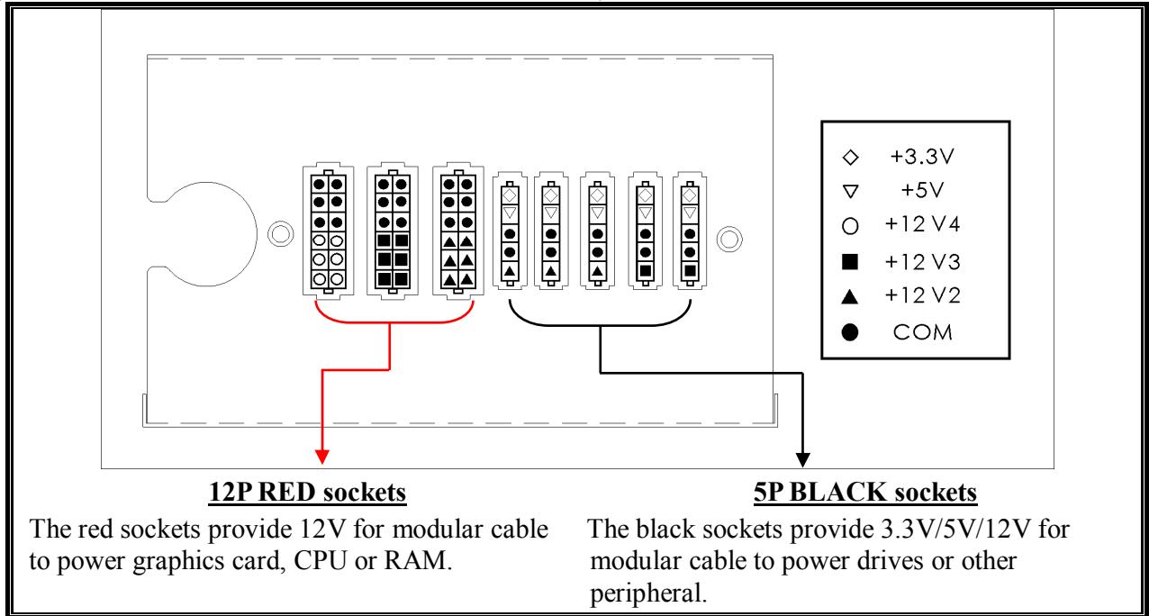
- This product incorporates multiple 12V rails over current protection. If you let many peripherals consume the power on only one 12V rail, it may trigger the over current protection and shut down the system. Please re-direct certain peripheral power cable to other 12V rail to share the current loading to ensure highest stability and safety.
| 24P Mainboard For new generations of ATX/EEB/CEB server/workstation MB. | |
| 8P CPU +12V Native cable, 12V rail supplied by 12V1 (750/850/1000W) 8-pin configuration supports multi-CPU server/workstation systems and some single extreme CPU systems. | |
| 4+4P(8P) CPU+12V, in combined mode Native cable, 12V rail supplied by 12V1 8-pin configuration supports multi-CPU server/workstation systems and some single extreme CPU systems. | |
| 4+4P(8P) CPU+12V, in split mode Native cable, 12V rail supplied by 12V1 4-pin configuration supports certain single CPU systems. Some multi-CPU workstation/server system might also need this extra 4-pin 12V connector. Please use the connector with “12V” marking. | |
| 6+2P (8P) PCI Express, in combined mode 12V rail supplied by 12V4 on native cables (850/1000W) 8-pin configuration supports latest extreme graphic cards, which require 8-pin PCI-E connector. | |
| 6+2P (8P) PCI Express, in split mode / 6P PCI Express 12V rail supplied by 12V4 on native cables (850/1000W) 6-pin configuration supports most performance PCI-E graphic cards, which require 6-pin PCI-E connector. | |
| SATA #1 For SATA/SAS drives. | |
| 4P Molex #2 For IDE/SCSI/SAS drives or some AGP graphic card with traditional 4P power in socket. | |
| FDD For floppy drive or certain add-on card. |
1 Some SATA drives might accept SATA or 4P Molex power. Normally, use either one of power connector to power the driver, BUT NOT BOTH! Please check the drive's manual for details.
2 Some MB might require this connector to share the +12V current from 24-pin Mainboard connector to PCI-E slot. If your system has multiple extreme graphic cards, please plug this connector to MB correspond socket and check the MB's manual for details.
- MODULAR CABLES SUPPLIED
Use ONLY genuine ENERMAX modular cables coming with ENERMAX PSU. Third party cables might not be compatible and might cause damage to your PSU and/or system, and use of third party cable shall void PSU warranty.
| EMC014-G: 2 x 6+2P (8P) PCI-E 2.0 Modular cable for 1 or 2 performance PCI Express graphic cards, which needs 6P or 8P PCI-E connector. | |
| EMC019-G: 4 x SATA drives Modular cable for SATA/SAS drives like ODD and HDD. | |
| EMC020-G: 4 x 4P Molex (IDE/SCSI) drives & 1 x FDD connector Modular cable for IDE/SCSI/SAS drives and peripheral, plus 1 FDD power connector. | |
| EMC021-G: 2 x SATA & 2 x 4P Molex Modular cable for SATA/SAS/IDE/SCSI drives and other peripherals. |
Special note for System Integrators: If your system requires special modular cable configuration or design, please contact an ENERMAX sales representative.
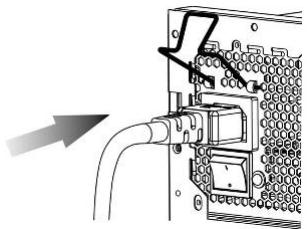
| Attaching the modular cable to PSU 5-pin / 12-pin connector on modular cable and PSU's modular socket has an arrow mark. To make correct connection is easy: 1. Black connector to black socket, and red to red. 2. Arrow mark to arrow mark. 3. Then you can easily plug in the connector. | |
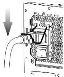
| Detaching the modular cable from PSU 5-pin / 12-pin connector on modular cable has two hooks to lock with the PSU's modular sockets. When unplug the modular cable from PSU, please press two hooks together and gently pull out the cable. |
BOOTING YOUR SYSTEM
Before booting your system, please check that:
- Main power connector (24P) is properly connected.
- CPU +12V power connector (4 or 8P configuration), and/or a 4P Molex connector (if required by MB) is properly connected.
- All other needed connectors are properly connected.
- AC cord is properly connected to wall outlet and PSU AC inlet.
- Close your system chassis.
- Turn on the PSU by switching the ON/OFF switch to "ON", and your system is ready.
PROTECTION, SAFETY & SECURITY
This ENERMAX PSU features multiple protections. In case of most abnormal situations, the power supply will automatically turn off to avoid potential danger to itself and other PC components. It is usually a malfunction of components or user's negligence to trigger off a protection event. In such circumstance, please check your PC devices and working environment for malfunction:
- Turn I/O switch of power supply into "O" position, or disconnect AC cord from wall plug and power supply AC inlet.
- Check PSU for temperature by simply touching it. If it is very hot, this can be caused by malfunction of case fans or the PSU fan itself and/or wrong positioning of your PC.
- Wait some minutes until PSU cools off.
- Reconnect AC cord to wall plug and power supply AC inlet.
- Turn I/O switch of power supply into "I" position, and reboot your system.
- Check, if all fans are working.
- Contact technical support of the respective manufacturer of the component which you think might be the cause to the problem. (e.g. MB, GPU or PSU)
If you have any question or need support, please contact your reseller or nearest ENERMAX subsidiary/agent or ENERMAX headquarters service center.
Benutzerhandbuch
3AIIHTA, MEPbI IPEIOCTOPOXHOCTH IIIPABUNIA TEXHNK INE3OIACHOCTH
bI ENERMAX ochaiueh HeCKoJIbKIMn cpeCTBaAMn 3aIHTbI. B 6OJIbIIHHCTBe aHOMaJIbHbIX cHTyaIIN bIOK IITaHna ABToMaTHUeCKN BbIKJIHOaETcra IIЯ IpeIoTbPaIeHnI IOBpeJKeHnI bIи IpyTHX KOMIOHeTOB PIK. 3aIHTa O6bIyHO cpaTaIBaer BCJIeCTBHe HEnCIIpaBHOCtN KOMIOHeTOB IIK IJIH He6peKHOCTH IoiJIb3OBaTeJIe. B TaKoI cHTyaIIN IpoBepbTe NcIIpaBHOCtY yCTpOietB IIK n ycIOBnA 3KCIJIyAtaIIHN.
- OTKJIIOHTHe IINTaHHe BII, IIepeBdIy BbIKJIOUaTeJIb B IOJIIOKeHne «O», HJIN OTcoEiHHNb Ka6JIb IIepeMeHHOrToKoAOT 3JIeKtprueckoI po3ETKn H BXODHOrO rHe3Ja IIepeMeHHOrToKa bII.
- Пюоверы TeMпьатуpy BП, ИрнкocHyBинсь K HeMy. Иретрв BП может 6ыт bВi3BaH HeNcIIpaBHO BeHTnJIaTOpOB KOpIyca ПК ИЛВ BeHTnJIaTopa BП, JIN6O HeIIpaBnJIbHBiM pa3MeIeHHeM ПК.
- IIOJOKJIte HeCKOJIbKO MmHyT, IOKa BII He oCTbIHET.
4.Полсоeингte Ka6eЛь ПеременHorO ToKa K 3JIeKtpnueckoу po3etke И К BXODHOMy ГHe3dY ПеременHorO ToKa BII. - IpebeIte BbIKIOHaeJIb BI IN IOIOKeHne «I» II bBbIOJIHNTE Ipee3aIpy3Ky cNCTeMbI.
- IpoBepbTe pa6oTocOc6Hocb cHCTeMbI.
- O6paHTTeCb B CJIyK6y TexHnueckOI IOJIePJKN IpoH3BOJITeJI KOMIOHeHTa, KOtOpbI, BO3MOJHO, BbI3bIBAeT IIpo6JIeMy, HApIpIMep MaTePHNcKo IIJaIbI, rpaΦnueckOIIaTbI NII BII.
C BOIIPOcAMH 3a IIOJIePJKKoI O6paIIaITeCb K MeCTHOMy IIpoIaBcy HJIN B 6JIHKaIIHIN HJHaJI HJIN B IIpeIcTaBHTeJIbCTBO ENERMAX, JIn60 B rOJIoBHOI cepBnCHbI ζeHTp ENERMAX.