GA-Z87X-OC - Carte mère GIGABYTE - Free user manual and instructions
Find the device manual for free GA-Z87X-OC GIGABYTE in PDF.
Download the instructions for your Carte mère in PDF format for free! Find your manual GA-Z87X-OC - GIGABYTE and take your electronic device back in hand. On this page are published all the documents necessary for the use of your device. GA-Z87X-OC by GIGABYTE.
USER MANUAL GA-Z87X-OC GIGABYTE
User's Manual Rev. 1001
12ME-Z87PD3-1001R We, Manufacturerlmporter GT. Technology
Address: Dectare that the product
Product Type: Motherboard Product Name: GA-287P-03
conforms vil he essential
I 2004/08EC EMC Directive I] Conducton & Radiated Erissions: F1 mmuni
FA 2006/85/Ec LVD Directive
I] Restriction of use of certain substances in electronic equipment:
ENG0950-1:2006+A11:2009
‘This product does not contain any ofine restricted
substances listed in Annex
and applications banned by
DECLARATION OF CONFORMITY Per FCC Part 2 Section 2.1077(a)
C Responsible Party Name:G.B.T. INC. (U.S.A.)
Address: 17358 Railroad Street City of Industry, CA 91748 Phone/Fax No: (626) 854-9338/ (626) 854-9326 hereby declares that the product Product Name: Motherboard Model Number: GA-ZS7P-D3
Conforms to the following specifications:
ion 15.107(a) and Section 15.109
Supplementary Information: This device complies with part 15 ofthe FCC Rules. Operation is subject to the follow 1) This device may not cause harmfül and (2) his device must accept any inference received, including that may cause undesired operation.
Representative Person’s Name: ERIC LU Signature: Er
Copyright © 2013 GIGA-BYTE TECHNOLOGY CO. LTD. All rights reserved. The trademarks mentioned in this manual are legally registered to their respective owners.
Information in this manual is protected by copyright laws and is the property of GIGABYTE. Changes to the specifications and features in this manual may be made by GIGABYTE without prior notice.
No part of this manual may be reproduced, copied, translated, transmitted, or published in any form or by any means without GIGABYTE's prior written permission.
Documentation Classifications In order to assist in the use of this product, GIGABYTE provides the following types of documentations:
M For quick set-up of the product, read the Quick Installation Guide included with the product. M For detailed product information, carefull read the Users Manual.
For product-related information, check on our website at: http:/mww.gigabyte.com
Identifying Your Motherboard Revision The revision number on your motherboard looks like this: "REV: X.X." For example, "REV:
1.0" means the revision of the motherboard is 1.0. Check your motherboard revision before updating motherboard BIOS, drivers, or when looking for technical information.
Box Contents. Optional Items GA-Z87P-D3 Motherboard Layout... GA-Z87P-D3 Motherboard Block Diagram
Chapter 1 Hardware Installation
CORRE Installation Precautions Product Specifications. Installing the CPU and CPU Cooler .
Chapter 5 Unique Features. 5-1 BIOS Update Utilities .
5-1-1 Updating the BIOS with the Q-Flash Utility.
5-1-2 Updating the BIOS with the @BIOS Utility .
2. Configuring S/PDIF In/Out… 6-1-3 Configuring Microphone Recording 6-1-4 Using the Sound Recorder 6-2 Troubleshooting. Frequently Asked Questions... Troubleshooting Procedure …
GA-Z87P-D3 motherboard Motherboard driver disk Users Manual
Quick Installation Guide Two SATA 6Gb/s cables 1/0 Shield
The box contents above are for reference only and the actual items shall depend on the product package you obtain. The box contents are subject to change without nolice.
3.5" Front Panel with 2 USB 3.0/2.0 ports (Part No. 12CR1-FPX582-2°R) HDMl-to-DVI adapter (Part No. 12CT2-HDMI01-1*R)
4 PCI PCIe to PCI Bridge
ER For detailed product informationllmitation(s), refer to "1-2 Product Specifications."
Installation Precautions
The motherboard contains numerous delicate electronic circuits and components which can become damaged as a result of electrostatic discharge (ESD). Prior to installation, carefully read the user's manual and follow these procedures:
Prior to installation, make sure the chassis is suitable for the motherboard.
Prior to installation, do not remove or break motherboard S/N (Serial Number) sticker or warranty sticker provided by your dealer. These stickers are required for warranty validation. Always remove the AC power by unplugging the power cord from the power outlet before installing or removing the motherboard or other hardware components.
When connecting hardware components to the internal connectors on the motherboard, make sure they are connected tightly and securely.
When handling the motherboard, avoid touching any metal leads or connectors.
lt is best to wear an electrostatic discharge (ESD) wrist strap when handling electronic components such as a motherboard, CPU or memory. If you do not have an ESD wrist strap, keep your hands dry and first touch a metal object to eliminate static electricity.
Prior to installing the motherboard, please have it on top of an antistatic pad or within an electrostatic shielding container.
Before unplugging the power supply cable from the motherboard, make sure the power supply has been turned off.
Before turning on the power, make sure the power supply voltage has been set according to the local voltage standard.
Before using the product, please verify that all cables and power connectors of your hardware components are connected.
To prevent damage to the motherboard, do not allow screws to come in contact with the motherboard circuit or its components.
Make sure there are no leftover screws or metal components placed on the motherboard or Within the computer casing.
Do not place the computer system on an uneven surface.
Do not place the computer system in a high-temperature environment.
Turning on the computer power during the installation process can lead to damage to system components as well as physical harm to the user.
If you are uncertain about any installation steps or have a problem related to the use of the product, please consult a certified computer technician.
-9- Hardware Installation
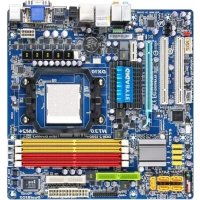
1-2 Product Specifications
CPU Support for Intel Core” 17 processors/Intel® Core” 15 processors/ Intel® Core” i3 processors/Intel® Pentium? processors/Intel? Celeron® processors in the LGAÏ150 package
(Go to GIGABYTE's website for the latest CPU support list.)
L3 cache varies with CPU
Dual channel memory architecture Support for DDR3 1600/1333 MHz memory modules
Support for non-ECC memory modules
Support for Extreme Memory Profile (XMP) memory modules
(Go to GIGABYTE's website for the latest supported memory speeds and memory modules.)
Integrated Graphics Processor:
= 1x HDMI por, supporing a maximum resolution of 4096x2160 *__ Support for HDMI 1 4a version.
= Maximum shared memory of 1 GB Audio
Reallek® ALCB87 codec: High Definition Audio 2/4/5.1/7.1-channel * To configure 7.1-channel audio, you have to use an HD front panel audio module and enable the muli-channel audio feature through the audio driver. Support for S/PDIF Outin
Realtek® GbE LAN chip (10/10/1000 Mbit)
TxPCI Express x16 slot, running at x16 (PCIEX16) * For oplimum performance, if only one PCI Express graphics card is t be instaled, be sure to instal in the PCIEX16 slot. {The PCIEX16 slot confoms to PCI Express 3.0 standard.) 1 xPCI Express x16 slot, running at x4 (PCIEX4) {The PCIEX4 slot confoms to PCI Express 2.0 standard.) 4xPCI slots
@ Mult-Graphics Technology
Support for AMD CrossFire”" technology
Chipset: = 6x SATA6Gb/s connectors supporting up to 6 SATA 6Gb/s devices = Support for RAID 0, RAID 1, RAID 5, and RAID 10
= Upto6USB 3.0/2. ports (4 ports on he back panel, 2 ports available through the intemal USB header)
= Upto8USB 2.0/1.1 ports (2 ports on the back panel, 6 ports available through the intemal USB headers)
Hardware Installation
x 24-pin ATX main power connector 1 x 8-pin ATX 12V power connector 1 x CPU fan header
1 x Clear CMOS jumper
3 x audio jacks (Line In/Line Out/Microphone)
System voltage detection CPU/System temperature detection CPU/System fan speed detection CPU/System overheating waming CPU/System fan fai waming
Use of licensed AMI EFI BIOS Support for DualBlOS"
PnP 1.0a, DMI 2.0, SM BIOS 2.6, ACPI 2.0a
-11- Hardware Installation
Support for Q-Flash Support for Xpress Install
Support for APP Center *_Avalable applications in APP Center may difer by mothetboard model. Supported functions ofeach application may als differ depending on motherboard specificatons.
Support for ONJOFF Charge
* GIGABYTE reserves the right lo make any changes Lo the product specifications and product-related information without
* Please visit the Support & DownloadslUtility page on GIGABYTE's website to check the supported operating systems) for the software listed in the "Unique Features” and "Bundled Software" column.
Installing the CPU and CPU Cooler
Read the following guidelines before you begin to install the CPU Make sure that the motherboard supports the CPU.
(Go to GIGABYTE's website for the latest CPU support list)
Always tum of the computer and unplug the power cord from the power outlet before instaling the CPU to prevent hardware damage.
Locate the pin one of the CPU. The CPU cannot be inserted if oriented incorrect. (Or you may locate the notches on both sides of the CPU and alignment keys on the CPU socket.)
Apply an even and thin layer of thermal grease on the surface of the CPU Do not turn on the computer ifthe CPU cooler is not installed, otherwise overheating and damage ofthe CPU may occur.
Set the CPU host frequency in accordance with the CPU specifcations. It is not recommended that the system bus frequency be set beyond hardware specifications since it does not meet the standard requirements for the peripherals. If you wish to set the frequency beyond the standard speciications, please do so according to your hardware speciications including the CPU, graphics card, memory, hard drive, etc.
Installing the CPU A. Locate the alignment keys on the motherboard CPU socket and the notches on the CPU.
Algnment Key Algnment Key
Pin One Comer afthe CPU Socket
LGAT150 CPU Notch Notch
rangle Pin One Making on the CPU
-13- Hardware Installation
B. Follow the steps below to correctly install the CPU into the motherboard CPU socket.
Before installing the CPU, make sure to turn offthe computer and unplug the power cord from À the power outlet to prevent damage to the CPU. + To protectthe socket contacts, do not remove the protectve plastic cover unless the CPU is
inserted into the CPU socket. Save the cover properly and replace it if the CPU is removed.
Gently press the CPU socket lever handle down and away from the socket with your finger. Then completely lift the CPU socket lever and the metal load plate/plastic cover will be lifted as well.
Step 3 Once the CPU is properly inserted, carefully replace the load plate. When replacing the load plate, make sure the front end of the load plate is under the shoulder screw Then press the CPU socket lever. The protective plastic cover may pop off from the load plate during the process of engaging the lever. Remove the cover. (Save the cover properiy and always replace it when the CPU is not installed.)
Hold the CPU with your thumb and index fingers. Align the CPU pin one marking (triangle) with the pin one corner ofthe CPU socket (or you may align the CPU notches with the socket alignment keys) and gent insert the CPU into position.
Finally, secure the lever under its retention tab to complete the installation of the CPU.
Hold the CPU socket lever by the handle, not the lever base portion.
Hardware Installation
1-3-2 Installing the CPU Cooler
Follow the steps below to correct install the CPU cooler on the motherboard. (The following procedure uses
Intel boxed cooler as the example cooler.)
Step 1 Apply an even and thin layer of thermal grease on the surface of the installed CPU.
Step 3 Place the cooler atop the CPU, aligning the four push pins through the pin holes on the motherboard. Push down on the push pins diagonall.
Step 5 After the installation, check the back of the motherboard. If the push pin is inserted as the picture above shows, the installation is complete
Ca Mae Direction of Push Pin ie Aron Sign
Before installing the cooler, note the direction ofthe arrowsign C+ on the male push pin. (Turingthe push pin along the direction of arrow is to remove the cooler, on the contrary is to install.)
Step 4 You should hear a"cick” when pushing doun each push pin. Check that the Male and Female push pins are joined closely.
{Refer to your CPU cooler installation manual or instructions on installng the cooler.)
Final, attach the power connector of the CPU Cooler to the CPU fan header (CPU_FAN) on the motherboard
Use extreme care when removing the CPU cooler because the thermal greaseltape betuieen the CPU cooler and CPU may adhere tothe CPU. Inadequately removing the CPU cooler may damage the CPU.
Hardware Installation
1-4 Installing the Memory
Read the following guidelines before you begin to install the memory: À + Make sure thatthe motherboard supports the memory. Ii recommended that memory of the same
capacity, brand, speed, and chips be used. (Go to GIGABYTE's website for the latest supported memory speeds and memory modules.)
+ Always tum off the computer and unplug the power cord from the power outlet before installing the memory to prevent hardware damage
+ Memory modules have à foolproof design. Amemory module can be installed in only one direction. I you are unable to insert the memory, Switch the direction
1-41 Dual Channel Memory Configuration
This motherboard provides four DDR3 memory sockets and supports Dual Channel Technology. After the memory is installed, the BIOS will automatically detect the specificalions and capacity of the memory. Enabling Dual Channel memory mode will double the original memory bandwidth
The four DDR3 memory sockets are divided into two channels and each channel has to memory sockets as following:
» Channel A: DDR3_1, DDR3_3
»> Channel B: DDR3_2, DDR3_4
(SS=Single-Sised, DS=Double-Sised, =
Due to CPU limitations, read the following guidelines before instalng the memory in Dual Channel mode. 1... Dual Channel mode cannot be enabled if only one DDR3 memory module is installed 2... When enabling Dual Channel mode with two or four memory modules, itis recommended that memory of the same capacity, brand, speed, and chips be used. For oplimum performance, when enabling Dual Channel mode with two memory modules, we recommend that you install them in the DDR3_1 and DDR3_2 sockets.
Hardware Installation -16-
1-42 Installing a Memory
Before installing a memory module, make sure to turn off the computer and unplug the power  cord from the power outlet to prevent damage to the memory module. DDR3 and DDR2 DIMM are not compatible to each other or DDR DIMMs. Be sure to install DDR3 DIMMS on this motherboard.
ADDR3 memory module has a notch, soit can only ftin one direction. Follow the steps below to correct install your memory modules in the memory sockets:
Step 1 Note the orientation of the memory module. Spread the retaining clips atboth ends of he memory socket. Place the memory module on the socket. As indicated in the picture on the left, place your fingers on the top edge of the memory, push down on the memory and insert it verically into the memory socket.
Step 2 The clips at both ends of the socket will snap into place when the memory module is securely inserted.
-17- Hardware Installation
1-5 Installing an Expansion Card
Read the following guidelines before you begin to instal an expansion card
À Make sure the motherboard supports the expansion card. Carelull read the manual that came with your expansion card.
Always tum of the computer and unplug the power cord from the power outlet before installing an
expansion card to prevent hardware damage.
PCI Express x16 Slot
Follow the steps below to correct install your expansion card in the expansion slot. Locate an expansion slot that supports your card. Remove the metal slot cover from the chassis back panel. Align the card with the slot, and press down on the card until it is fully seated in the slot.
Make sure the metal contacts on the card are completely inserted into the slot.
Secure the card's metal bracket to the chassis back panel vith a screuw.
After instaling all expansion cards, replace the chassis cover(s).
Turn on your computer. If necessary, go to BIOS Setup to make any required BIOS changes for your expansion card(s).
Install the driver provided with the expansion card in your operating system.
Example: Instaling and Removing a PCI Express Graphics Card + Installing à Graphics Card: Gently push down on the top edge of the card until it is fully inserted into the PCI Express slot. Make sure the card is securely seated in the slot and does not rock.
+ Removing the Card: Gently push back on the lever on the slot and then lift the card straight out from the slot.
Hardware Installation -18-
1-6 Back Panel Connectors
e PS/2 Keyboard and PS/2 Mouse Port
Use the upper port (green) to connect a PS/2 mouse and the lower port (purple) to connect a PS2 keyboard. © Serial Port
Use the serial port to connect devices such as a mouse, modem or other peripherals. © HDMI Port
A7 7e HDMI port is HDCP complant and supports Dolby True HD and DTS HD oreenmanrne Master Audio formats. It also supports up to 192KHz/24bit 8-channel LPCM audio output. You can use this port to connect your HDMI-Supported monitor. The maximum supported resolution is 4096x2160, but the actual resolutions supported are dependent on {he monitor being used.
After installing the HDMI device, make sure to set the default sound playback device to HDMI
{The item name may differ depending on your operating system. The screenshot below is from Windows 8.)
In Windows 8, select Start>Control Panel>Hardware and Sound>Sound>Playback, set ntel(R) Display Audio to the default playback device.
The USB 3.0 port supports the USB 3.0 specifcation and is compatible to the USB 2.0/1.1 speciication: Use this port for USB devices Use this port for USB devices such as a USB keyboard/mouse, USB printer, USB flash drive and etc.
Note) The DVI-D port does not support D-Sub connection by adapter.
-19- Hardware Installation
© RJ-45 LAN Port The Gigabit Ethemet LAN port provides Internet connection at up to 1 Gbps data rate. The following describes the states of he LAN port LEDS.
| | State Description State Description
The USB port supports the USB 2.0/1.1 specification. Use this port for USB devices such as a USB Keyboard/mouse, USB printer, USB flash drive and etc.
& Line In Jack (Blue) The default line in jack. Use this audio jack for line in devices such as an optical drive, walkman, etc. # Line Out Jack (Green)
The default line out jack. Use this audio jack for a headphone or 2-channel speaker. This jack can be used to connect front speakers in a 4/5.1/7.1-channel audio configuration.
© Mic In Jack (Pink) The default Mic in jack. Microphones must be connected to this jack.
The audio jacks can be reconfigured to perform different functions via the audio software. Only microphones still MUST be connected to the default Mic in jack. Refer to the instructions on setting up a 2/4/5.1/7.1-channel audio configuration in Chapter 6, "Configuring 2/4/5.1/7.1-Channel Audio."
device and then remove it from the motherboard. + When removing the cable, pull it straight out from the connector. Do not rock it side to side to prevent an electrical short inside the cable connector.
î +. When removing the cable connected to a back panel connector, first remove the cable from your
Hardware Installation -20-
Read the following guidelines before connecting extemal devices
First make sure your devices are compliant with the connectors you wish to connect.
Before instalng the devices, be sure to turn off the devices and your computer. Unplug the power cord from the power oulet to prevent damage to the devices.
After installing the device and before tuning on he computer, make sure the device cable has been securely aftached to the connector on the motherboard.
-21- Hardware Installation
1/2) ATX_12V_2X4/ATX (2x4 12V Power Connector and 2x12 Main Power Connector) With the use ofthe power connector, he power supply can supply enough stable power to all the components on the motherboard. Before connecting the power connector, fist make sure the power supply is tumed off and all devices are propeny installed. The power connector possesses a foolproof design. Connect the power supply cable to the power connector in the correct orientation The 12V power connector mainly supplies power to the CPU. fthe 12V power connector is not connected, the computer wil not start. To meet expansion requirements, itis recommended that a power supply that can withstand high power consumption be used (500W or greater). If a power supply is used that does not provide the required power, the result can lead to an unstable or unbootable system.
The motherboard has a 4-pin CPU fan header (CPU_FAN), to 4-pin (SYS_FAN1, SYS_FAN2) and a 3-pin {SYS_FAN3) system fan headers. Most fan headers possess a foolproof insertion design. When connecting à fan cable, be sure to connect in the correct orientation (the black connector wire is the ground wire) The speed control function requires the use of a fan with fan speed control design. For optimum heat dissipation, itis recommended that a system fan be installed inside the chassis.
CPUFAN _ Pin No. | Definiion E:] nn F-:] 1 GND [ ME ( |] CPU.FAN 3 TSense D 4__| Seed Control ‘ SYS FAMISYS FANZ [mi ï Pin No. | Defniion Fu, à 1 [ew 0 il 2 | +2VT Speed Control ES 3 Sense =>, SEM SEA a [vec . == SYS FANS: — LL nie Pin No. | Definiion ec Ÿ> 1 [ew (| ‘ ME SYS_FAN3 3 [NA
may result in damage to the CPU or the system may hang
+ Be sure to connect fan cables to he fan headers to prevent your CPU and system from overheating. Overheating À + _ These fan headers are not configuration jumper blocks. Do not place a jumper cap on the headers.
The battery provides power to keep the values (such as BIOS configurations, date, and time information) inthe CMOS when the computer is tumed off. Replace the battery when the battery voltage drops to a low level, or the CMOS values may not be accurate or may be lost
You may clear he CMOS values by removing the battery
Turn off Your computer and unplug the power cord.
Gently remove the battery from the battery holder and wait for one minute. (Or use a metal objectlike a screwdriverto touch the positive and negative terminals of the battery holder, making them short for 5 seconds.) Replace the battery.
Plug in the power cord and restart your computer.
Always tum of your computer and unplug the power cord before replacing the battery.
Replace the battery with an equivalentone. Danger of explosion if the battery is replaced with an incorrect model Contact the place of purchase or local dealer you are not able to replace the battery by yourself or uncertain about the battery model
When instaling the battery, note the orientation of the positive side (+) and the negative side (-) of the battery {the posive side should face up)
Used batteries must be handled in accordance with local environmental regulations.
-23- Hardware Installation
6) SATA3 0/1/2/3/4/5 (SATA 6Gb/s Connectors) The SATA connectors conform to SATA 6Gb/s standard and are compatible with SATA 3Gb/s and SATA 1.5Gb/ standard. Each SATA connector supports a single SATA device. The Intel® Z87 Chipset supports RAID 0, RAID f, RAID 5, and RAID 10. Refer to Chapter 3, "Configuring SATA Hard Drive(s);"forinstructions on configuring à RAID array.
LOST Pin No. | Definition GND TXP TXN GND RXN RXP GND
used, the total number of hard drives must be an even number. A RAID 5 configuration requires at least three hard dives. (The total number of hard drives does not have Lo be an even number)
+ ARAID 10 configuration requires four hard drives.
F_AUDIO (Front Panel Audio Header)
The front panel audio header supports Intel High Definition audio (HD) and AC'97 audio. You may connect your chassis front panel audio module to this header. Make sure the wire assignments of the module connector match the pin assignments of the motherboard header. Incorrect connection between the module connector and the motherboard header will make the device unable to work or even damage it.
œ A RAID 0 or RAID 1 configuration requires at least io hard drives. If more than two hard drives are to be
1 For HD Front Panel Audio: For AC'97 Front Panel Audio: Pin No. ] Definition: Pin No. ] Definition 1 [ML 1 [Me EU 2 [en 3 [MCZR 3 | MICPower Î 4 [ACZDET 4 [Nc ù 5 [INR 5 |[LneoutR 6 [en 6 [Nc NE 7 | FAUDO D T [Nc 8 |Nopin 8 |NoPin Sfar 9 JUNEL 9 |LneOu(L) ——“ 10 [en rm [Nc
+ The front panel audio header supports HD audio by default. your chassis provides an AC'97 front panel audio (C3 module, refer to the instructions on how to activate AC'97 functionalty via the audio software in Chapter 6, "Configuring 2/4/5.1/7 1-Channel Audio." Audio signals wil be present on both of the front and back panel audio connections simultaneousl. 1 you want to mute the back panel audio (only supported when using an HD front panel audio module) refer to Chapter 6, "Configuring 2/4/5.1/7.1-Channel Audio." + Some chassis provide a front panel audio module that has separated connectors on each wire instead of a single plug. For information about connecting Ihe front panel audio module that has different wire assignments, please contact the chassis manufacturer.
Hardware Installation -24-
8) F_PANEL (Front Panel Header)
Connectthe power switch, reset switch, speaker, chassis intrusion switch/sensor and system status indicator on the chassis to this header according to the pin assignments below. Note the positive and negative pins before connecting the cables.
PLED/PWR_LED (Power LED, Vellow/Purple): System Siaus [LED | Connects to the power status indicator on the chassis front panel. The LED So On isonwhenthe system is operating. The LED is off when the system is in S3/ sasass — or | S4 sleep state or powered off (S5)
PW (Power Suitch, Red) Connects to the power switch on the chassis front panel. You may configure the way to tu off your system using the power switch (refer to Chapter 2, "BIOS Setup," "Power Management" for more information)
SPEAK (Speaker, Orange)
Connects to the speaker on the chassis front panel. The system reports system startup status by issuing a beep code. One single short beep will be heard if no problem is detected at system startup.
HD (Hard Drive Activity LED, Blue)
Connects to the hard drive activity LED on the chassis front panel. The LED is on when he hard drive is reading or writing data.
RES (Reset Switch, Green)
Connects to the reset switch on the chassis front panel. Press the reset switch to restart the computer ifthe computer freezes and fals to perform a normal restant.
CI (Chassis Intrusion Header, Gray)
Connects to the chassis intrusion switch/sensor on the chassis that can detect ifthe chassis cover has been removed. This function requires a chassis with a chassis intrusion suitch/sensor.
The front panel design may differ by chassis. A front panel module mainly consists of power switch, reset switch, power LED, hard drive activity LED, speaker and etc. When connecting your chassis front panel module to this header, make sure the wire assignments and the pin assignments are matched correct.
-25- Hardware Installation
9) SPDIF_O (S/PDIF Out Header) This header supports digital S/PDIF Out and connects a SIPDIF digital audio cable (provided by expansion cards) for digital audio output from your motherboard to certain expansion cards like graphics cards and sound cards. For example, some graphics cards may require you to use a S/PDIF digital audio cable for digital audio output from your motherboard to your graphics card if you wish to connect an HDMI display to the graphics card and have digital audio output from the HDMI display atthe same time. For information about connecting the S/PDIF digital audio cable, carefully read the manual for your expansion card.
Pin No. | Definition 8 1 | SPDIFO 1 2 [en
SPDIF_IN (S/PDIF In Header) This header supports digital S/PDIF In and can connect to an audio device that support digital audio out via an optional SIPDIF In cable. For purchasing the optional SIPDIF In cable, please contact the local dealer.
11) F_USB30 (USB 3.0/2.0 Header) The header conforms to USB 3.0/2.0 specication and can provide two USB ports. For purchasing the optional 3.5" front panel that provides two USB 3.0/2.0 ports, please contact the local dealer.
+ Do not plug the IEEE 1394 bracket (2x5-pin) cable into the USB 2.0/1.1 header. + Prior toinstaling the USB bracket, be sure to turn off your computer and unplug the power cord from the power outlet to prevent damage to the USB bracket.
% B Pin No. | Definition Pin No. | Definition
T [STE 14 | GND 2 |AFD- 15 |PDS 3 [Po 16 |GND 4 |ERR 17 [Por 5 |pDt 18 |GND 6 [INT 1 [AK T_|Px 2 |GN 8 |SLN- 21 |BUSY 9 [Pos 2 |GN 10 | GND 23 ÎPE 1 |PD4 24 | NoPin 12 _[GND 25 [Sicr
13 [PD5 2 |GN Hardware Installation -28-
15) CLR_CMOS (Clear CMOS Jumper) Use this jumper to clear the BIOS configurations and reset the CMOS values to factory defaults. To clear the CMOS values, use a metal object like a screwdriver to touch the two pins for a few seconds.
@D … Short: Clear CMOS Values
+_ Always turn off your computer and unplug the power cord from the power outlet before clearing the CMOS values
+_ After system restart, go to BIOS Setup to load factory defaults (select Load Optimized Defaults) or manually configure the BIOS settings (refer to Chapter 2, "BIOS Setup" for BIOS configurations)
-29- Hardware Installation
Chapter 2 BIOS Setup
BIOS (Basic Input and Output System) records hardware parameters of the system in the CMOS on the motherboard. lts major functions include conducting the Power-On Self-Test (POST) during system startup, saving system parameters and loading operating system, etc. BIOS includes a BIOS Setup program that allows the user to modify basic system configuration settings or to activate certain system features.
When the power is turned off, the battery on the motherboard supplies the necessary power to the CMOS to
Keep the configuration values in the CMOS To access the BIOS Setup program, press the <Delete> key during the POST wien the pouer is tumed on.
To upgrade the BIOS, use either the GIGABYTE Q-Flash or @BIOS utility.
+ Q-Flashalows the userto quickly and easily upgrade or back up BIOS without entering the operating system:
+ @BIOS is a Windows-based utility that searches and downloads the latest version of BIOS from the Internet and updates the BIOS.
For instructions on using the Q-Flash and @BIOS utlties, refer to Chapter 5, "BIOS Update Utlties."
+ Because BIOS flashing is potentally risk, if you do not encounter problems using the current À version of BIOS, it is recommended that you not flash the BIOS. To flash the BIOS, do it with caution. Inadequate BIOS flashing may result in system malfunction.
ILis recommended that you not alter the default setings (unless you need to) to prevent system instabilty or other unexpected results. Inadequately altering the settings may result in system's failure to boot. IFthis occurs, tr to clear the CMOS values and reset the board to default values (Refer to the "Load Optimized Default" section in this chapter or introductions of the battery/clear CMOS jumper in Chapter 1 for how to clear the CMOS values.)
The following startup Logo screen will appear when {he computer boots
<DEL>: BIOS SETUPQ-FLASH Press the <Delete> key to enter BIOS Setup or to access the Q-Flash utilty in BIOS Setup.
<F9>: SYSTEM INFORMATION Press the <F9> key lo display your system information
<F12>: BOOT MENU Boot Menu allows you to set the first boot device without entering BIOS Setup. In Boot Menu, use the up arrow key <1> or the down arrow key <4> to select the first boot device, then press <Enter> to accept. The system wil boot from the device immediately. Note: The setting in Boot Menu is effective for one time only. After system restart, the device boot order wil st be based on BIOS Setup settings
<END>: Q-FLASH Press the <End> key to access the Q-Flash utlty directly without having to enter BIOS Setup first
A. Windows Mode (Default)
Differing from traditional UEFI interface, the Windows Mode provides a fancy and user-friendly BIOS environment where users can easily point and click through various settings and make adjustments for optimum performance. In Windows Mode, you can use your mouse to move through the option menus for quick configuration or you can click Classic Setup under the Shortcuts list on the right of the screen or press <F2> to switch to the traditional BIOS Setup screen.
B. Classic Setup In Classic Setup, you can press the arrow keys on your keyboard to move among the items and press <Enter> to accept or enter a sub-menu. Or you can use your mouse to select the item you want
(Sample BIOS Version:
— Setup Menus Switch to Enter Q-Flash Windows Select Default Mode Language Help
Configuration Items Current Settings
<#>KPage Up> Increase the numeric value or make changes <>KPage Dour» Decrease Ihe numeric value or make changes
<F2> Switch to Windows Mode <F5> Restore the previous BIOS settings for the current submenus <F7> Load the Optimized BIOS default settings for the current submenus <F8> Access the Q-Flash utility <F9> Display system information <F10> Save all the changes and exit the BIOS Setup program <F12> Caplure the current screen as an image and save it to your USB drive Es Main Menu: Exit the BIOS Setup program Submenus: Exit current submenu BIOS Setup Menus = MIT.
Use this menu to configure the clock, frequency, and voltages of your CPU and memory, etc. Or check the system/CPU temperatures, voltages, and fan speeds.
mn System Use this menu to configure the default language used by the BIOS and system time and date. This menu also displays information on the devices connected to the SATA ports.
m BIOS Features Use this menu to configure the device boot order, advanced features available on the CPU, and the primary display adapter.
M Peripherals Use this menu to configure all peripheral devices, such as SATA, USB, integrated audio, and integrated LAN, etc.
M Power Management Use this menu to configure all the power-saving functions.
m Save & Exit Save all the changes made in the BIOS Setup program to the CMOS and exit BIOS Setup. You can save the current BIOS settings to a profil or load optimized defaults for optimal-performance system operations:
system to its defaults. The BIOS Setup menus described in this chapter are for reference only and may differ by BIOS version:
ER ‘When the system is not stable as usual, select the Load Optimized Defaults item to set your
GIGABYTE - UEFI DualBlOS
on your overall system configurations. Incorrectly doing overclockiovervoltage may result in damage to CPU, chipset, or memory and reduce the useful ife of these components. This page is for advanced users only and we recommend you not to alter the default settings to prevent system instability or other unexpected results. (Inadequately altering the settings may result in system's failure to boot. If this oceurs, clear he CMOS values and reset the board to default values.)
î Whether the system will work stably with the overclocklovervoltage settings you made is dependent
GIGABYTE - UEFI DualBlOS This section provides information on the BIOS version, CPU base clock, CPU frequency, memory frequency, total memory size, CPU temperature, Vcore, and memory voltage
> M.LT. Current Status This screen provides information on CPU/memory frequencies/parameters.
> Advanced Frequency Settings
CTENE CPU Base Clock
Allows you to manually set the CPU base clock in 0.01 MHz increments. (Default: Auto)
Important: It is highly recommended that the CPU frequency be set in accordance with the CPU specifications.
Host/PCle Clock Frequency (No)
Allows you to manually set the host clock frequency (which controls CPU, PCIe, and memory frequencies) in 0.01 MHz increments.
This item is configurable only when CPU Base Clock is set to Manual.
Processor Base Clock (Gear Ratio) (Not)
Allows you to configure the Processor Base Clock by multiplying the Host/PCle Clock Frequency by several preset host clock multpliers. This item is configurable only when CPU Base Clock is set to Manual. Host Clock Value
This value is determined by multiplying the Host/PCle Clock Frequency value by the Processor Base Clock (Gear Ratio) value.
Processor Graphics Clock
Alows you to setthe onboard graphics clock. The adjustable range is from 400 MHz to 4000 MHz. (Default: Auto)
CPU Clock Ratio Allows you to alter the clock ratio for the installed CPU. The adjustable range is dependent on the CPU being installed. CPU Frequency Displays the current operating CPU frequency. (Note) Thisitemis present only when you install a CPU that supports this feature. For more information about Intels CPUS' unique features, please visit Intel's website.
> Advanced CPU Core Features
EL re Visio Male gti Ca
CPU Clock Ratio, CPU Frequency
The settings above are synchronous to those under the same items on the Advanced Frequency Settings menu.
Alows you to set the CPU PLL. Auto lets the BIOS automatically configure this setting. (Default: Auto) Filter PLL Level
Allows you to set the Filter PLL. Auto lets the BIOS automatically configure this setting. (Default: Auto) Uncore Ratio
Allows you to set the CPU Uncore ratio. The adjustable range is dependent on the CPU being used Uncore Frequency
Displays the current CPU Uncore frequency.
Intel(R) Turbo Boost Technology (note)
Allows you to determine whether to enable the Intel CPU Turbo Boost technology. Auto lets the BIOS automatically configure this setting. (Default: Auto)
Allows you to set the CPU Turbo ratios for different number of active cores. Auto sets the CPU Turbo ratios according to the CPU specifications. (Default: Auto)
Turbo Power Limit (Watts)
Allows you to set a power limit for CPU Turbo mode. When the CPU power consumption exceeds the specified power limit, the CPU will automatically reduce the core frequency in order to reduce the power. Auto sets the power limit according to the CPU specifications. (Default: Auto)
Core Current Limit (Amps)
Allows you to set a current limit for CPU Turbo mode. When the CPU current exceeds the specified current limit, the CPU will automatically reduce the core frequency in order to reduce the current. Auto sets the power limit according to the CPU specifcations. (Default: Auto)
(Note) Thisitemis present only when you install a CPU that supports this feature. For more information about Intels PUS unique features, please visit Intel website.
CPU Core Enabled (vor 1)
Allows you to determine whether to enable all CPU cores. Auto lets the BIOS automatically configure this setting. (Default: Auto)
Hyper-Threading Technology (Not 1
Alows you to determine whether to enable mult-threading technology when using an Intels CPU that supports this function. This feature only works for operating systems that support multi-processor mode. Auto lets the BIOS automatically configure this setting. (Default: Auto)
CPU Enhanced Halt (C1E) (Note 1)
Enables or disables Intel® CPU Enhanced Halt (C1E) function, a CPU power-saving function in system halt state. When enabled, the CPU core frequency and voltage will be reduced during system hal state to decrease power consumption. Auto lets the BIOS automatically configure this setting. (Default: Auto) C3/C6 State Support Now 1
Allows you to determine whether to let the CPU enter C3/C6 mode in system halt state. When enabled, the CPU core frequency and voltage will be reduced during system halt state to decrease power consumption. The C3/C6 state is a more enhanced power-saving state than C1. Auto lets the BIOS automatically configure this setting. (Default: Auto)
CPU Thermal Monitor (Note 1)
Enables or disables Intel® Thermal Monitor function, a CPU overheating protection function. When enabled, the CPU core frequency and voltage will be reduced when the CPU is overheated. Auto lets the BIOS automatically configure this setting. (Default: Auto)
CPU EIST Function (wo 1)
Enables or disables Enhanced Intels Speed Step Technology (EIST). Depending on CPU loading, Intel EIST technology can dynamically and effectively lower the CPU voltage and core frequency to decrease average power consumption and heat production. Auto lets the BIOS automatically configure this setting (Default: Auto)
Extreme Memory Profile (X.M.P.) (vote 2) Allows the BIOS to read the SPD data on XMP memory module(s) to enhance memory performance when enabled.
» Disabled Disables this function. (Default) » Profile Uses Profile 1 settings.
» Profile2 we2 Uses Profile 2 settings. System Memory Multiplier
Alows you to set the system memory multiplier. Auto sets memory multiplier according to memory SPD data. (Default: Auto)
Memory Frequency (MHz)
The first memory frequency value is the normal operating frequency of the memory being used: the second isthe memory frequency thatis automatically adjusted according to the System Memory Muttiplier settings.
Note 1). Thisitemis present only when you install a CPU that supports this feature. For more information about
Intels CPUs' unique features, please visit Intel's website.
{Note 2). This item is present only when you install a CPU and a memory module that support his feature.
Allows the system to operate at three different performance levels.
» Normal Lets the system operate at its basic performance level. » Turbo Lets the system operate at its good performance level. (Default) » Extreme Lets the system operate at its best performance level.
DRAM Timing Selectable
Quick and Expert allows the Channel Interleaving, Rank Interleaving, and memory timing settings below to be configurable. Options are: Auto (default), Quick, Expert.
When using a non-XMP memory module or Extreme Memory Profile (X.M.P.)is setto Disabled, this item will display as 1.50V. When Extreme Memory Profile (X.M.P.) is set to Profilei or Profile2, this item will display the value based on the SPD data on the XMP memory.
Channel Interleaving
Enables or disables memory channel interleaving. Enabled allows the system to simultaneously access different channels of the memory to increase memory performance and stability. Auto lets the BIOS automatically configure this setting. (Default: Auto)
Enables or disables memory rank interleaving. Enabled allows the system to simultaneously access different ranks of the memory to increase memory performance and stability. Auto lets the BIOS automatically configure this setting. (Default: Auto)
Note) This item is present only when you install a CPU and a memory module that support this feature.
> Channel A/B Timing Settings
GIGABYTE - UEFI DualBlOS D Vies Me Eotieh — C-a
This sub-menu provides memory timing settings for each channel of memory. The respective timing setting screens are configurable only when DRAM Timing Selectable is set to Quick or Expert. Note: Your system may become unstable or fall to boot ter you make changes on the memory timings. Ifthis occurs, please reset the board to default values by loading optimized defaults or clearing the CMOS values.
> CPU Core Voltage Control This section provides CPU voltage control options.
GIGABYTE - UEFI DualBlOS GIGABYTE - UEFI DualBlOS Reset Case Open Status
» Disabled Keeps or clears the record of previous chassis intrusion status. (Default)
# Enabled Clears the record of previous chassis intrusion status and the Case Open field will Show "No" at next boot.
Displays the detection status of the chassis intrusion detection device attached to the motherboard CI
header. lf the system chassis cover is removed, this field will show "Yes", otherwise it will show “No”. To
clear the chassis intrusion status record, set Reset Case Open Status to Enabled, save the settings to
the CMOS, and then restart your system.
CPU Vcore/CPU VRIN/DRAM Voltage/+3.3V/+5V/+12V/CPU VAXG Displays the current system voltages.
CPU/System Warning Temperature
Sets the warning threshold for CPU/system temperature. When CPU temperature exceeds the threshold,
BIOS will emit warning sound. Options are: Disabled (default), 60°C/140F, 70-C/158:F, 80°C/1766F,
CPU Fan Speed Control (CPU_FAN Connector)
Allows you to determine whether to enable the fan speed control function and adjust the fan speed.
# Normal Allows the fan to run at different speeds according to the CPU temperature. You can adjust the fan speed with EasyTune based on your system requirements. (Default)
» Silent Allows the fan to run at slow speeds.
# Manual Allows you to control the fan speed under the Slope PWM item.
» Disabled Allows the fan to run at full speeds.
Slope PWM Allows you to control the fan speed. This item is configurable only when CPU Fan Speed Control is set
to Manual. Options are: 0.75 PWM value /eC - 2.50 PWM value /eC.
st System Fan Speed Control (SYS_FAN1 Connector)
Allows you to determine whether to enable the fan speed control function and adjust the fan speed.
» Normal Allows the fan to run at different speeds according to the system temperature. You can adjust the fan speed with EasyTune based on your system requirements. (Default)
» Silent Allows the fan to run at slow speeds.
# Manual Allows you to control the fan speed under the Slope PWM item.
» Disabled Allows the fan to run at full speeds.
Slope PWM Allows you to control the fan speed. This item is configurable only when 1st System Fan Speed Control
is set to Manual. Options are: 0.75 PWM value /eC - 2.50 PWM value C.
2nd System Fan Speed Control (SYS_FAN2 Connector)
Allows you to determine whether to enable the fan speed control function and adjust the fan speed.
» Normal Allows the fan to run at different speeds according to the system temperature. (Default)
» Silent Allows the fan to run at slow speeds.
# Manual Allows you to control the fan speed under the Slope PWM item.
» Disabled Allows the fan to run at full speeds.
Slope PWM Allows you to control the fan speed. This item is configurable only when 2nd System Fan Speed Control
is set to Manual. Options are: 0.75 PWM value /eC - 2.50 PWM value C.
> Miscellaneous Settings
GIGABYTE - UEFI DualBlOS CRE D Mis Visio Male tic Ca
PEG Gen3 Slot Configuration Allows you to set the operation mode ofthe PCI Express slots to Gen 1, Gen 2, or Gen 3. Actual operation
mode is subject to the hardware specification of each slot. For example, the PCI Express x slots can support up to Gen 2 mode only. Auto lets the BIOS automatically configure this setting. (Default: Auto)
Legacy BenchMark Enhancement Allows you to determine whether to enhance some legacy benchmark performance. (Default: Disabled)
This section provides information on your CPU, memory, motherboard model, and BIOS version. You can also select the default language used by the BIOS and manually set the system time.
Selects the default language used by the BIOS.
Sets the system date. The date format is week (read-only), month, date, and year. Use <Enter> to switch between ihe Month, Date, and Year fields and use the <Page Up> or <Page Down> key to set the desired value.
Sets the system time. The time format is hour, minute, and second. For example, 1 p.m. is 13:0:0. Use <Enter> to switch between the Hour, Minute, and Second fields and use the <Page Up> or <Page Down> key to set the desired value.
Displays the current access level depending on the type of password protection used. (If no password is set, the default will display as Administrator.) The Administrator level allows you to make changes to all BIOS settings: the User level only allows you to make changes to certain BIOS settings but not all.
Boot Option Priorities
Specifies the overall boot order from the available devices. For example, you can set hard drive as the first priority (Boot Option #1) and DVD ROM drive as the second priority (Boot Option #2). The list only displays the device with the highest priority for a specific type. For example, only hard drive defined as the first priority on the Hard Drive BBS Priorities submenu will be presented here.
Removable storage devices that support GPT format will be prefixed with "UEFI:" string on the boot device list. To boot from an operating system that supports GPT parttoning, select the device prefixed with "UEFI" string.
Orif you want to install an operating system that supports GPT partiioning such as Windows 7 64-bit, select the optical drive that contains the Windows 7 64-bit installation disk and is prefixed with "UEFI:" string.
Hard Drive/CD/DVD ROM Drive/Floppy Drive/Network Device BBS Priorities
Specifies the boot order for a specific device type, such as hard drives, optical drives, floppy disk drives, and devices that support Boot from LAN function, etc. Press <Enter> on this item to enter the submenu that presents the devices of the same type that are connected. This item is present only if at least one device for this type is installed.
Bootup NumLock State
Enables or disables Numlock feature on the numeric keypad of the keyboard after the POST. (Default: Enabled)
Specifies whether a password is required every time the system boots, or only when you enter BIOS Setup. After configuring this item, set the password(s) under the Administrator Password/User Password item.
» Setup Apassword is only required for entering the BIOS Setup program. » System Apasswordis required for booting he system and for entering he BIOS Setup program. (Default)
Full Screen LOGO Show Alows you to determine whether to display the GIGABYTE Logo at system startup. Disabled skips the GIGABYTE Logo when the system starts up. (Default: Enabled)
Fast Boot Enables or disables Fast Boot to shorten the OS boot process. Ultra Fast provides the fastest bootup speed. (Default: Disabled)
VGA Support Alows you to select which type of operating system to boot. » Auto Enables legacy option ROM only.
» EFI Driver Enables EFl option ROM. (Default) This item is configurable only when Fast Boot is set to Enabled or Ultra Fast.
USB Support » Disabled Al USB devices are disabled before the OS boot process completes. » Full Initial Al USB devices are functional in the operating system and during the POST.
» Partial Initial Part of the USB devices are disabled before the OS boot process completes. (Default) This item is configurable only when Fast Boot is set to Enabled. This item is disabled when Fast Boot is set to Ultra Fast.
PS2 Devices Support » Disabled All PS/2 devices are disabled before the OS boot process completes. » Full Initial All PS/2 devices are functional in the operating system and during the POST. (Default)
This item is configurable only when Fast Boot is set to Enabled. This item is disabled when Fast Boot is set to Ultra Fast.
NetWork Stack Driver Support
» Disabled Disables booting from the network. (Default)
# Enabled Enables booting from the network.
This item is configurable only when Fast Boot is set to Enabled or Ultra Fast.
Limit CPUID Maximum (Not)
Allows you to determine whether to limit CPUID maximum value. Set this item to Disabled for Windows XP operating system; set this item to Enabled for legacy operating system such as Windows NT4.0. (Default Disabled)
Execute Disable Bit(vow)
Enables or disables Intel Execute Disable Bit function. This function may enhance protection for the computer, reducing exposure to viruses and malicious buffer overflow attacks when working with its supporting software and system. (Default: Enabled)
Intel Virtualization Technology (vote)
Enables or disables Intel® Virtualization Technology. Virtualization enhanced by Intel® Virtualization Technology willallow a platform to run multiple operating systems and applications in independent partitions. With virtualization, one computer system can function as multiple virtual systems. (Default: Enabled) Intel TXT(LT) Support (ot)
Enables or disables Intel® Trusted Execution Technology (Intel® TXT). Intel® Trusted Execution Technology provides a hardware-based security foundation. (Default: Disabled)
Dynamic Storage Accelerator
Enables or disables Intel® Dynamic Storage Accelerator. When enabled, the hard drive 1/0 performance will be adjusted according to hard drive load. (Default: Disabled)
Enables or disablesintel® Virtualization Technology for Directed 1/0. (Default: Enabled)
Alows you to select the operating system to be installed. (Default: Other OS)
Enables or disables UEFI CSM (Compatibility Support Module) to support a legacy PC boot process.
+ Always Enables UEFI CSM. (Default)
» Never Disables UEFI CSM and supports UEFI BIOS boot process only.
This item is configurable only when OS Type is set to Windows 8 or Windows 8 WHQL.
Alows you to select which type of operating system to boot.
» UEFI and Legacy Allows booting from operating systems that support legacy option ROM or UEFI option ROM. (Default)
» Legacy only Allows booting from operating systems that only support legacy option ROM.
» UEFI only Allows booting from operating systems that only support UEFI option ROM.
This item is configurable only when CSM Support is set to Always.
LAN PXE Boot Option ROM Allows you to select whether to enable the legacy option ROM for the LAN controller. (Default: Disabled)
This item is configurable only when CSM Support is set to Always.
This item is configurable only when CSM Support is set to Always.
Other PCI Device ROM Priority
Allows you to select whether to enable the UEFI or Legacy option ROM for the PCI device controller other than the LAN, storage device, and graphics controllers.
> UEFI OpROM Enables UEFI option ROM only. (Default)
Disables or enables booting from the network to install a GPT format OS, such as installing the OS from the Windows Deployment Services server. (Default: Disabled)
Enables or disables IPv4 PXE Support. This item is configurable only when Network stack is enabled. Ipv6 PXE Support
Enables or disables IPv6 PXE Support. This item is configurable only when Network stack is enabled.
Alows you to configure an administrator password. Press <Enter> on this item, type the password, and then press <Enter. You will be requested to confirm the password. Type the password again and press <Enter>. You must enter the administrator password (or user password) at system startup and when entering BIOS Setup. Differing from the user password, the administrator password allows you to make changes to all BIOS settings.
Alows you to configure a user password. Press <Enter> on this item, type the password, and then press <Enter>. You will be requested to confirm the password. Type he password again and press <Enter>. You must enter the administrator password (or user password) at system startup and when entering BIOS Setup. However, the user password only allows you to make changes to certain BIOS settings but not all
Specifies the frstinitiation of the monitor display from the installed PCI graphics card, PCI Express graphics card or the onboard graphics.
Sets the onboard graphics as the first display. Sets the graphics card on the PCIEX16 slot as the first display. (Default) Sets the graphics card on the PCI slot as the first display.
Allows you to determine the operating mode for the xHCI controller in OS.
This mode is available only vihen the BIOS supports the xHCI controller in the pre-boot environment. This mode is similar to Auto, but it adds the capabilty to route the ports to xHCI or EHCI according to setting used in previous boots (for non-G3 boot) in the pre-boot environment, This allows the use of USB 3.0 devices prior to OS boot. xHCI controller enabling and rerouting should follow the steps in Auto, when previous boot routs ports to EHCI. Note: This is the recommended mode when BIOS has xHCI pre- boot support. (Default)
BIOS routes the sharable ports to EHCI controller. Then it uses ACPI protocols to provide an option to enable the xHCI controller and reroute the sharable ports. Note This is the recommended mode when BIOS does NOT have xHCI pre-boot support Allshared ports are eventuallyrouted to the xHCI controller during the BIOS boot process. I BIOS does not have pre-boot support for the xHCI controller, it should initilly route the sharable ports to the EHCI controller and then prior to OS boot it should route the ports to xHCI controller. Note: OS has to provide support for the xHCI controller in this mode. Ifthe OS does not provide support all sharable ports won't work.
The USB 3.0 ports are routed to the EHCI controller and the xHCI controller is tumed of. AI USB 3.0 devices function as High Speed devices regardiess of xHCI software supportavailability.
Allows you to determine whether to routthe USB 3.0 ports to the xHCI or EHCI controller before booting to OS, and also provides you with options to manually rout each USB
3.0/2.0 port to xHCI or EHCI BIOS Setup
If you wish to install a 3rd party add-in audio card instead of using the onboard audio, set this item to Disabled.
Enables or disables the onboard graphics function. (Default: Enabled)
Internal Graphics Memory Size
Alows you to set the onboard graphics memory size. Options are: 32M-1024M. (Default: 64M)
DVMT Total Memory Size
Allows you to allocate the DVMT memory size of the onboard graphics. Options are: 128M, 256M, MAX. (Default: MAX)
Intel(R) Rapid Start Technology
Enables or disables Intel® Rapid Start Technology. (Default: Disabled)
Allows USB keyboard/mouse to be used in MS-DOS. (Default: Enabled)
Determines whether to enable XHCI Hand-off feature for an operating system without XHCI Hand-off support. (Default: Enabled)
Determines whether to enable EHCI Hand-off feature for an operating system without EHCI Hand-off support. (Default: Disabled)
Displays alistof connected USB mass storage devices. This item appears only when a USB storage device is installed.
Enables or disables the integrated SATA controllers. (Default: Enabled)
Enables or disables RAID for the SATA controllers integrated in the Intel Z87 Chipset or configures the
SATA controllers to AHCI mode.
» IDE Configures the SATA controller to IDE mode.
» AHCI Configures the SATA controller to AHCI mode. Advanced Host Controller Interface (AHCI) is an interface specification that allows the storage driver to enable advanced Serial ATA features such as Native Command Queuing and hot plug. (Default)
Enables or disable the hot plug capability for each SATA port. (Default: Disabled)
This item is configurable only when Parallel Portis set to Enabled. Selects an operating mode for the onboard parallel (LPT) port. (Default), EPP Mode (Enhanced Parallel Port), ECP Mode (Extended Capabilties Port), EPP Mode & ECP Mode.
Realtek PCIe GBE Family Controller This sub-menu provides information on LAN configuration.
2-7 Power Management
Determines whether to power on the system at a desired time. (Default: Disabled)
If enabled, set the date and time as following:
» Wake up day: Turn on the system at a specific time on each day or on a specific day in a month
» Wake up hour/minutelsecond: Set the time at which the system will be powered on automatically.
Note: When using this function, avoid inadequate shutdown from the operating system or removal of the
AC power, or the settings may not be effective.
ErP Determines whether to let the system consume least power in S5 (shutdown) state. (Default: Disabled)
Note: When this item is set to Enabled, the following functions will become unavailable: PME event wake
up, power on by mouse, power on by keyboard, and wake on LAN.
Soft-Off by PWR-BTTN Configures the way to turn off the computer in MS-DOS mode using the power button
» Instant-Off Press he power button and then the system will be tumed off instant. (Default)
» Delay 4 Sec. Press and hold the power button for 4 seconds to tum off the system. If the power button is pressed for less than 4 seconds, the system will enter suspend mode.
Allows you to determine whether to let the onboard graphics enter standby mode to decrease power
consumption. (Default: Enabled)
AC BACK Determines the state of {he system after the retum of power from an AC power loss » Memory The system retums to it last known awake state upon the return of the AC power.
» Always On The systemis tumed on upon the return of the AC power. » Always Off The system stays off upon the retum of the AC power. (Default)
‘7 Power On By Keyboard Allows the system to be tumed on by a PS/2 keyboard wake-up event. Note: To use this function, you need an ATX power supply providing at least 1A on the +5VSB lead.
» Disabled Disables this function. (Default)
» Any Key Press any key to tum on the system.
» Keyboard 98 Press POWER button on the Windows 98 keyboard to turn on the system. » Password Set a password with 1-5 characters to tum on the system.
‘Power On Password Set the password when Power On by Keyboard is set to Password. Press <Enter> on this item and set a password with up to 5 characters and then press <Enter> to accept. To tum on the system, enter the password and press <Enter>. Note: To cancel the password, press <Enter> on this item. When prompted for the password, press <Enter> again without entering the password to clear the password settings.
Allows the system to be turned on by a PS/2 mouse wake-up event.
Note: To use {his function, you need an ATX power supply providing at least 1A on the +5VSB lead. » Disabled Disables this function. (Default)
» Move Move the mouse to turn on the system.
» Double Click Double click on left button on the mouse to tum on the system.
Press <Enter> on this item and select Yes to load the optimal BIOS default settings. The BIOS defaults settings help the system to operate in optimum state. Always load the Optimized defaults after updating the BIOS or after clearing the CMOS values.
Allows you to select a device to boot immediately. Press <Enter> on the device you select and select Yes to confirm. Your system wil restart automatically and boot from that device.
This function allows you to save the current BIOS settings to a profil. You can create up to 8 profiles and save as Setup Profile 1- Setup Profile 8. Press <Enter> to complete. Or you can select Select File in HDD/USB/FDD to save the profile to your storage device.
I your system becomes unstable and you have loaded the BIOS default settings, you can use this function to load the BIOS settings from a profile created before, without the hassles of reconfiguring îhe BIOS settings. First select the profile you wish to load and then press <Enter> to complete. You can select Select File in HDD/USB/FDD to input the profile previously created from your storage device or load the profile automatically created by the BIOS, such as reverting the BIOS settings to the last settings that worked properly (last known good record).
Chapter3 C RAID Levels RAID 0 RAID 1 RAID 5 RAID 10 Minimum Number of Hard 22 2 23 24 Drives Array Capacity | Number of hard Size of the smallest | (Number of hard {Number of hard drives * Size ofthe | drive drives -1)* Size of | drives/2) * Size of thel smallest drive the smallest drive smallest drive Fault Tolerance No Yes Yes Yes
To configure SATA hard drives), follow the steps below: A. Install SATA hard drive(s) in your computer.
B. Configure SATA controller mode in BIOS Setup.
C. Configure a RAID array in RAID BIOS. (1)
D. Install the SATA RAID/AHCI driver and operating system. 12
Before you begin Please prepare: + Atleastiwo SATA hard drives (to ensure optimal performance, itis recommended that you use do hard drives with identical model and capacity). If you do not want to create RAID, you may prepare only one hard drive. + Windows 8/7 setup disk. + Motherboard driver disk. + AUSB thumb drivev
3-1 Configuring SATA Controllers
À. Installing SATA hard drive(s) in your computer Attach one end of the SATA signal cable to the rear of the SATA hard drive and the other end to available SATA port on the motherboard. Then connect the power connector from your power supply to the hard drive.
{Note 1). Skip this step if you do not want to create RAID array on the SATA controller. {Note 2) Required when the SATA controller is set to AHCI or RAID mode.
-57- Configuring SATA Hard Drive(s)
B. Configuring SATA controller mode in BIOS Setup Make sure to configure the SATA controller mode correctly in system BIOS Setup.
Step 1 Turn on your computer and press <Delete> Lo enter BIOS Setup during the POST (Power-On Self-Test). Go to Peripherals\SATA Configuration, make sure SATA Controllers is enabled. To create RAID, set SATA Mode Selection to RAID (Figure 1). l you do not want to create RAID, set this item to IDE or AHCI GIGABVTE - UE DualiOS
# 2% (0) S DETTE Ds Bab
Step 2 I you want to configure UEFI RAID, follow the steps in "C-1." To enter the legacy RAID ROM, save the settings and exit BIOS Setup. Refer to "C-2" for more information.
The actual BIOS Setup menu options you wil| see shall depend on the motherboard you have and
Dr BIOS Setup menus described in this section may diflr from the exact settings for your motherboard. the BIOS version:
Configuring SATA Hard Drive(s) RTE C-1. UEFI RAID Configuration This mode supports Windows 8 64-bit installation only.
Step 1 In BIOS Setup, go to BIOS Features and set OS Type to Windows 8 and CSM Support to Never. (Figure 2) Save the changes and exit BIOS Setup.
After he system reboot, enter BIOS Setup again. Then enter the PeripheralslIntel(R) Rapid Storage Technology sub-menu (Figure 3)
GIGABYTE - UEFI DualBlOS Figure 3
RTE Confguring SATA Hard Drive(s)
Step 3 Onthe Intel(R) Rapid Storage Technology menu, press <Enter> on Create RAID Volume to enterthe Create RAID Volume screen. Enter a volume name with 1-16 letters (letters cannot be special characters) under the Name item and press <Enter. Then, select a RAID level (Figure 4). RAID levels supported include RAID 0. RAID 1, RAID 10, and RAID 5 (the selections available depend on the number ofthe hard drives beinginstalled).
Step 4 Under Select Disks item, select ihe hard drives to be included in the RAID array. Press the <Space> key on the hard drives to be selected (selected hard drives are marked with "X"). Then set he strpe block size (Figure 5). The stipe block size can be set from 4 KB to 128 KB. Once you have selected the stripe block size, set
Step 5 After setting the capacity, move to Create Volume and press <Enter> Lo begin. (Figure 6) GIGABVTE - UE DualsiOS
After completing, you'l be brought back t the Intel(R) Rapid Storage Technology screen. Under RAID Volumes you can see the new RAID volume. To see more detailed information, press <Enter> on the volume to check
for information on RAID level, stripe block size, array name, and array capacity, etc. (Figure 7)
GIGABYTE - UEFI DualBlOS 2æ, &
L ER ture Etol QD Rat Stage Tool LE Figure 7
-6T- Confguring SATA Hard Drive(s)
Delete RAID Volume To delete a RAID array, press <Enter> on the volume to be deleted on the Intel(R) Rapid Storage Technology screen. After entering the RAID VOLUME INFO screen, press <Enter> on Delete to enter the Delete screen. Press <Enter> on Yes (Figure 8)
Configuring SATA Hard Drive(s) -&2-
C-2. Configuring Legacy RAID ROM Enter the Intel” legacy RAID BIOS setup utiity to configure a RAID array. Skip this step and proceed with the installation of Windows operating system for a non-RAID configuration.
Step 1 After the POST memory test begins and before the operating system boot begins, look for a message which says "Press <Ct-B to enter Configuration Utility" (Figure 9). Press <Ctr> + <b> to enterthe RAID Configuration Utility.
Technology - Option ROM - 1 3 Intel Corporation. AIl Ri
Step 3 After entering the CREATE VOLUME MENU screen, enter a volume name with 1-16 letters (letters cannot be special characters) under the Name item and press <Enter>. Then, select a RAID level (Figure 14). RAID levels supported include RAID 0, RAID f, RAID 10, and RAID 5 (the selections available depend on the number ofthe hard drives being installed). Press <Enter> to proceed.
Step 4 Under Disks item, select the hard drives to be included in the RAID array. only two hard drives are installed, theyvill be automatically assigned to the array. Setthe stripe block size (Figure 12) ifnecessary. The stripe block size can be set from 4 KB to 128 KB. Once you have selected the stripe block size, press <Enter>.
LCREATE VOLUME MENU ] me: Volume0 RAID Level : RAIDO(Stripe) Disi Strip Capacity: 1117 GB Syne: NA Create Volume
The following are typical values:
When completed, you can see detailed information about the RAID array in the DISK/VOLUME INFORMATION section, including the RAID level, stipe block size, array name, and array capacity, etc. (Figure 14)
4. Recovery Volume Options Delete RAID Volume
Now, you can proceed to install the SATA RAID/AHCI driver and operating system.
-65- Configuring SATA Hard Drive(s)
Recovery Volume Options Intel® Rapid Recover Technology provides data protection by allowing users to easily restore data and system operation using a designated recovery drive. With the Rapid Recovery Technology, which employs RAID 1 functional, users can copy the data from the master drive to the recovery dive: if needed, the data on the recovery drive can be restored back to the master drive.
+ The recovery drive must have equal or greater capacity than the master drive.
+ Arecovery volume can be created with two hard drives only. À recovery volume and a RAID array cannot co-exist in the system at the same lime, that is, if you have already created a recovery volume, you are unable to create a RAID array.
+ By default only the master drive can be viewed in the operating system: the recovery drive is hidden.
Step 1 Select Create RAID Volume in MAIN MENU and press <Enter> (Figure 15).
RAID Level : [REOVErN NA Capacity: 1117GB Sync: Continuous Create Volume
Step 3 Press <Enter> under the Select Disks em. In the SELECT DISKS box, press <Tab> on the hard drive you want to use for the master drive and press <Space> on the hard drive you want to use for the recovery drive. (Make sure the recovery drive has equal or larger capacity than the master drive.) Then press <Enter> to confim (Figure 17).
LCREATE VOLUME MENU ] Name RAID Level
Step 4 Under Sync, select Continuous or On Request (Figure 18). When set to Continuous, changes made to the data on the master drive will be automatically and continuously copied to the recovery drive when both hard drives are installed in the system. On Request allows users to update data from the master drive to the recovery drive manual using the Intel Rapid Storage Technology utility in the operating system. On Request also allows users to restore the master drive to a previous state.
LCREATE VOLUME MENU ] Name : _Volumeo RAID Level: Reco
NA 0.0 GB Continuous Create Volume
s updated manual Continuous: volume is updated automa
Step 5 Final press <Enter> on the Create Volume item to begin creating the Recovery Volume and follow the on- screen instructions to complete.
HE Confguring SATA Hard Drive(s)
To delete a RAID array, select Delete RAID Volume in MAIN MENU and press <Enter. In the DELETE VOLUME MENU section, use the up or doun arrow key to select the array to be deleted and press <Delete>. (When prompted to confirm your selection (Figure 19), press <Y> to confirm or <N> to abort.
LDELETE VOLUME MENU } Name Drives cit Status Bootable ume0 2 23,60 Normal
ALL DATA IN THE VOLUME WILL BE LOST!
Deleting a volume will reset the disks 10 non-RAID. ALL DISK DATA WILL BE DELETED. This does not app e olumes)
Acceleration Options
This option allows you to view the status of your accelerated drivelvolume (Figure 20) created using the Intel® IRST utility. In case you are unable to run the Intel IRST utility due to an application error or operating system issue, you will need to remove acceleration or manualy enable synchronization (Maximized mode only) using this option in the RAID ROM utility.
Select Acceleration Options in MAIN MENU and press <Enter>
To remove the acceleration, select the accelerated drivelvolume, press <R>, and press <Y> to confim:
To synchronize data from the cache device to the accelerated drivelvolume, press <S> and press <Y> to confim.
{ ACCELERATION OPTIONS }: Name y | Mode
ata from the cache device to ated Disk Volume
IT IS RECOMMENDED THAT YOU PERFORM À SYNCHRONIZATION BEFORE REMOVING ACCELERATION Figure 20
Configuring SATA Hard Drive(s) -68-
3-2 Installing the SATA RAID/AHCI Driver and Operating System
With the correct BIOS settings, you are ready to install Windows 8/7. À. Installing Windows 8/7
As Windows 7 already include Intel® SATA RAID/AHCI driver, you do not need to install separate RAID/AHCI driver during the Windows installation process. After the operating system is installed, we recommend that you install all required drivers from the motherboard driver disk using "Xpress Install to ensure system performance and compatibiity. To install Windows 8, refer to the steps below:
Step 1 Copy the IRST folder under BootDrv in the driver disk to your USB thumb drive.
Step 2 Boot from the Windows 8 setup disk and perform standard OS installation steps. When the screen requesting you to load the driver appears, select Browse.
Step 3 Insertthe USB thumb drive and then browse to the location ofthe driver. The locations ofthe divers are as follows: Windows 32-bit: \RSTI32Bit Windows 64-bit: \RSTI64Bit
Step 4 When a screen as shown in Figure 1 appears, select Intel(R) Desktop/Workstation/Server Express Chipset SATA RAID Controller and click Next to load the driver and continue the OS installation
-69- Configuring SATA Hard Drive(s)
B. Rebuilding an Array
Rebuilding is the process of restoring data to a hard drive from other drives in he array. Rebuilding applies only to fault-tolerant arrays such as RAID 1, RAID 5 or RAID 10 arrays. The procedures below assume a new drive is added to replace a failed drive to rebuild a RAID 1 array. (Note: The new drive must have equal or greater capacity than the old one.)
Turn off your computer and replace the failed hard drive with a new one. Restart your computer.
+ Enabling Automatic Rebuild Step 1
When the message "Press <Cir-1> to enter Configuration Utility" appears, press <Cti> + <b> to enter the RAID Configuration Utility. The following screen appears after you enter the RAID Configuration Utility.
DEGRADED VOLUME DETECTED Step 2 Select the new hard drive to add into the array to be rebuit and press <Enter>. The following screen appears, indicating that an automatic rebuild will be performed after you enter the operating system. If you do not enable automatic rebuild on this stage, you have to manualy rebuild the array in the operating system (see the next page for more details).
LMAIN MENU } 4. Recovery Volume Options 2. Delete RAID Volume ion Op
Disks 10 Non-RAID LDISK/VOLUME INFORMATION ]
Strip ie Status Bootable
Configuring SATA Hard Drive(s) -T0-
+ Performing the Rebuild in the Operating System While in the operating system, make sure the chipset driver has been installed from the motherboard driver disk. Then launch the Intel® Rapid Storage Technology utlty from the desktop.
Step 2: Select a new drive to rebuild the RAID and click Rebuild.
Step 1 Go to the Manage menu and click Rebuild to another disk in Manage Volume
The Status item on the left of the screen displays Step 3: the rebuild progress. After the RAID 1 volume rebuilding, the Status will display as Normal.
-71- Configuring SATA Hard Drive(s)
+ Restoring the Master Drive to a Previous State (for Recovery Volume only) When two hard drives are set to Recovery Volume in Update on Request mode, you can restore the master drive data to the last backup state when needed. For example, in case the master drive detects à virus, you can restore the recovery drive data to the master drive.
Step 1 Select 4. Recovery Volume Options in the MAIN MENU of the Intel® RAID Configuration Utility. On the RECOVERY VOLUMES OPTIONS menu, select Enable Only Recovery Disk to show he recovery drive in
the operating system. Follow the on-screen instructions to complete and exit the RAID Configuration Utility. Opion ROM tel Corporation. Al Righis
RECOVERY VOLUME OPTION 1. Enable Only R Disk 2. Enable Only Ma
Name Capacity - Bootable
volume to do 1 ation.
Step 3 Click Yes to begin the data recovery.
Step 2 Go to the Manage menu of the Intel® Rapid Storage Technology utlty and click Recover data in Manage Volume
| Step4: The Status item on the left of the screen displays Aflerthe recovery volume is completed, the Status the rebuild progress. will display as Normal.
Confguring SATA Hard Drive(s) -72-
apter 4 Drivers Installatio
Before installing the drivers, first install the operating system. (The following instructions use ER Windows 8 as the example operating system.) + After installng the operating system, insert the motherboard driver disk into your optical drive. Click on the message "Tap to choose what happens with this disc on he top-right comer of the screen and select "Run Run.exe." (Or go to My Computer, double-click the optical drive and ex-
ecute the Run.exe program.)
"Xpress Install ill automatically scan your system and then list al of the drivers that are recommended to install. You can click the Xpress Install button and "Xpress Install” will install all of he selected drivers. Or diick the arrow [] icon to individually install the drivers you need.
GIGABYTE | Xpress Install
when "Xpress Install’ installing the drivers. Failure to do so may affect the driver installation: + Some device drivers wil restart your system automatically during the driver installation. After the system restart, "Xpress Install will continue to instal other drivers
-73- Drivers Installation
This page displays the apps that GIGABYTE develops and some free soflware. You can select the apps you want and click the Install Æ] icon to begin the installation.
This page provides detailed information on the drivers on the driver disk. The Contact page provides contact information of the GIGABYTE Taiwan headquarter. You can click the URL on this page to link to the GIGA- BYTE website to check more information on the GIGABYTE headquarter or worlduide branch offices.
Drivers Installation -74-
apter Unique Features
5-1 BIOS Update Utilities
GIGABYTE motherboards provide to unique BIOS update tools, Q-Flash” and @BIOS”. GIGABYTE Q-Flash and @BIOS are easy-to-use and allow you to update {he BIOS without the need to enter MS-DOS mode. Additionally, this motherboard features the DualBlOS” design, which enhances protection for the safety and stability of your computer by adding one more physical BIOS chip.
What is DualBIOS"? Motherboards that support DualBIOS have two BIOS onboard, a main BIOS and a backup BIOS. Normal the system works on the main BIOS. However, i the main BIOS is corrupted or damaged, the backup BIOS will take over on the next system boot and copy the BIOS fil to the main BIOS to ensure normal system operation. For the sake of system safety, users cannot update the backup BIOS manual.
With Q-Flash you can update the system BIOS without having to enter operating systems like MS-DOS or Window first. Embedded in the BIOS, the Q-Flash tool frees you from {he hassles of going through complicated BIOS flashing process.
What is @BIOS"? @BIOS allows you to update the system BIOS while in the Windows environment. @BIOS will download the latest BIOS fille from the nearest @BIOS server site and update the BIOS.
5-11 Updating the BIOS with the Q-Flash Utility
From GIGABYTE's website, download the latest compressed BIOS update file that matches your motherboard model.
Extract the file and save the new BIOS file (e.g. Z87PD3.F1) to your USB flash drive or hard drive. Note: The USB flash drive or hard drive must use FAT32/16/12 file system.
Restart the system. During the POST, press the <End> key to enter Q-Flash. Note: You can access Q-Flash by either pressing the <End> key during the POST or pressing the <F8> key in BIOS Setup. However, ifthe BIOS update file is saved to a hard drive in RAID/AHCI mode or a hard drive attached to an independent SATA controller, use the <End> key during the POST to access Q-Flash.
Because BIOS flashing is potential risky, please do it with caution. Inadequate BIOS flashing may result in system malfunction
TS - Unique Fealures
B. Updating the BIOS In the main menu of Q-Flash, use the keyboard or mouse to select an item to execute. When updating the BIOS, choose the location where the BIOS file is saved. The following procedure assumes that you save the BIOS file to a USB flash drive.
1. Insert the USB flash drive containing the BIOS file into the computer. In the main menu of Q-Flash, select Update BIOS From Drive.
+_ The Save BIOS to Drive option allows you to save the current BIOS file.
Q-Flash only supports USB flash drive or hard drives using FAT32/16/12 flle system:
+_Ifthe BIOS update fl is saved to a hard drive in RAID/AHCI mode or a hard drive attached to an independent SATA controller, use the <End> key during the POST to access Q-Flash
2. Select USB Flash Drive.
Q-Flash Utility v1.0S Model Name 3 lrsion : Fle 04/09/20
IC 25L Series 16MB Updaie BIOS From Drive
3. Select the BIOS update file. À Make sure the BIOS update file matches your motherboard model.
Step 2 The process of the system reading the BIOS file from the USB flash drive is displayed on the screen. When the message "Are you sure to update BIOS?" appears, select Yes to begin the BIOS update. The monitor will display the update process
Do notturn off or restart the system when the system is readinglupdating the BIOS.
Do not remove the USB flash drive or hard drive when the system is updating the BIOS.
Step 3 The system will restart after the update process is complete.
Step 4 During the POST, press <Delete> to enter BIOS Setup. Select Load Optimized Defaults on the Save & Exit screen and press <Enter> to load BIOS defaults. System will re-detect all peripheral devices after a BIOS update, so we recommend that you reload BIOS defaults.
Select Yes to load BIOS defaults
Step 5 Select Save & Exit Setup and press <Enter>. And then select Yes to save settings to CMOS and exit BIOS Setup. The procedure is complete after he system restarts.
5-2 Updating the BIOS with the @BIOS Utility
In Windows, close all applications and TSR (Terminate and Stay Resident) programs. This helps prevent unexpected failures when performing a BIOS update.
Ifthe BIOS is being updated via the Intemet, ensure the Internet connection is stable and do NOT interrupt the Internet connection (for example, avoid a power loss or switching off the Internet). Failure to do so may result in a corrupted BIOS or a system that is unable to start
GIGABYTE product warranty does not cover any BIOS damage or system failure resuling from an inadequate BIOS flashing.
Using @BIOS . Update the BIOS Using the Internet Update Function: r Click Update from Server, select the @BIOS server site closest lo your location and EE then download the BIOS file that matches your motherboard model. Follow the on-screen = instructions to complete. Ithe BIOS update fl for your motherboard is not present on the @BIOS server site, please CA manually download the BIOS update file from GIGABYTE's website and follow the instructions in "Update the BIOS without Using the Internet Update Function" below.
. Update the BIOS without Using the Internet Update Function:
[EM Click Update from file, then select the location where you save the BIOS update file obtained L EN from the Intemet or through other source. Follow the on-screen instructions to complete.
Save the Current BIOS File:
[EN Click Save to file to save the current BIOS fille.
Change the Boot-up Logo:
Click Upload new image in Face-Wizard and you will be able to change the boot-up logo [SM with our own picture, creating a personalized boot-up screen. Click Backup current image to save the currently used boot-up logo.
e Supported image formats include jpg, bmp, and gif.
C. After Updating the BIOS Restart your system after updating the BIOS.
Make sure that the BIOS file to be flashed maïches your motherboard model. Updating the BIOS À with an incorrect BIOS file could cause your system not to boot
Do not turn off the system or remove the power during the BIOS update process, or the BIOS may corrupt and the system may not boot
GIGABYTE App Center gives you easy access to a weallh of GIGABYTE apps that help you get he most from your GIGABYTE motherboard "#, Using a simple, unified user interface, GIGABYTE App Center allows you to easily launch all GIGABYTE apps installed on your system, check related udpates online, and download the apps, drivers, and BIOS.
Running the APP Center
Insert the motherboard driver disk. On the Autorun screen, go to Application Softwarelinstall GIGABYTE Utilities to install GIGABYTE App Center and the selected apps. Restart your computer after the installation is complete. In Desktop mode, click the App Center icon PA in the notification area to launch the App Center utility (Figure 1). On the main menu, you can select an app to run or click Live Update to update an app online.
Ifthe App Center is closed, you can restart it by clicking the App Center icon on the Start menu. (Figure 2)
(Note) Available applications in APP Center may differ by motherboard model. Supported functions of each application may also differ depending on motherboard specifications.
GIGABYTE's EasyTune is a simple and easy-to-use interface that allows users to fine-tune their system settings or do overclocklovervoltage in Windows environment. The user-fendiy EasyTune interface also includes tabbed pages for CPU and memory information, leting users read their system-related information without the need to install additional software.
The System Information tab provides information on the installed CPU and motherboard
Smart Quick Boost provides you with differentlevels of CPU frequency to choose to achieve desired system performance. After making changes, be sure to restart your system for these changes to take effect. The Advanced menu allows you to change specific clock/frequency/ votlage settings.
The Smart Fan tab allows you to specify à Smart Fan mode. The Calibrate menu displays the detected inear fan speed for the fans on the motherboard from the fastest to the slowest. The Advanced menu allows you to set temperature thresholds, based on which the fan speed can be changed lineariy.
The System Alerts tab allows you to monitor hardware temperature, voltage and fan speed and set temperature/fan speed alarm
The 3D Power tab allows you to change power phase and voltage settings
Available functions in EasyTune may differ by motherboard model. Grayed-out area(s) indicates that the item is not configurable or the function is not supported.
as CPU, chipset, and memory and reduce the useful life of these components. Before you do the
î Incorrectiy doing overclock/overvoltage may result in damage to the hardware components such
overclocklovervoltage, make sure that you fully know each function of EasyTune, or system instability or other unexpected resulls may occur.
The GIGABYTE EZ Setup utility includes the following EZ' setups applications that wil offer greatly simplified install and configuration procedures: Disk Mode Switch, EZ Smart Response, EZ Rapid Start, EZ Smart Connect, and XHD.
Disk Mode Switch allows you to switch the operating mode for your hard drive even after its been installed with an operating system. Supported operating modes include IDE, AHCI, and RAID. You can select a disk mode and restart your computer after the selection
Native UEFI mode is not supported.
Be sure to reinstall the Intel” Rapid Storage Technology utility after you switch the disk mode.
A. System Requirements 1. An Intel® Chipset-based motherboard supporting this feature No 1 2. Intel® Core series processor
3. Intel® SATA controller set to RAID mode
4. Intel Rapid Storage Technology utility installed 1 1 5.
A conventional SATA disk and an SSD Windows 7 with SP1/Windows 8
original data on the SSD will be lost once you enable RAID mode # #, It is recommended that you
î If you have installed the operating system before confguring the Smart Response Technology, all back up the hard disk before enabling the Smart Response Technology.
B. Using EZ Smart Response Select EZ Smart Response and click Create. To disable this function, click Delete.
(Note 1). Before start, make sure you have installed the Intel® Rapid Storage Technology utility (version 11.5 or above)
(Note 2). The SSD works as a cache of the hard disk. The maximum cache memory size is 64 GB. If you use an SSD larger than 64 GB, the space beyond 64 GB can stil be used for storing your data.
(Note 3) The operating system must be installed to the SATA disk
(Note 4) Regardiess of the BIOS settings, be it IDE or AHCI mode, the system will be forced into RAID mode.
Unique Features -&2-
1. Intel® Rapid Start Technology enabled in BIOS Setup
2. An SSD with size larger than the total system memory
3. Windows 7 with SP1/Windows 8
4. AHCIRAID mode supported (please note if the SSD has been assigned as a member of a RAID array, it cannot be used to set up and Intel” Rapid Start store partition); IDE mode not supported
B. Using EZ Rapid Start
Select EZ Rapid Start and click Create. Then install the Intel” Rapid Start Technology utility and restart your computer to complete.
To disable this function, click Delete.
The default compressed space is the system memory size plus 2 GB. For example, ifthe system A memory size is 8 GB, the default compressed space is 8 GB plus 2 GB, so the SSD capacity will decrease by 10 GB. IFEZ Rapid Startis disabled, the decreased 10 GB wil be retumed to the SSD. I you want to upgrade your system memory, disable EZ Rapid Start first and re-instal it to ensure it can work normalh
(Note) Ifthe motherboard Chipset supports RAID, EZ Rapid Start wil force the Intel® SATA controllers into RAID mode. I not, the Intel® SATA controllers will be forced into AHCI mode.
1. Intel® Smart Connect Technology enabled in BIOS Setup 2. Windows 7 with SP1/Windows 8
3. Intel® Smart Connect Technology utility installed
4. Propery-working network connection
5. Programs added to the White List must be tumed on‘!
B. Using EZ Smart Connect Select EZ Smart Connect. Under File Name, select the apps to be auto-updated by Smart Connect. Double- click the app to add it to the Application permission list. (Double-click [DB to return to the previous directory)
GIGABYTE Note) This feature works best with programs designed to work automatically with the Internet to obtain their data such as Outlook?, Windows Live” Mail and Seesmic®.
XHD With GIGABYTE XHD * !, users can quickly configure à RAID-ready system for RAID 0 or RAID 1 when a new SATA drive is added. AÏ with a simple click of a button, XHD helps to enhance your hard drive read/vrite performance without the need for complex and time-consuming configurations.
A. System Requirements
1. An Intel® Chipset motherboard supporting RAID 2. Intel® SATA controllers set to RAID mode
3. Intel” Rapid Storage Technology utility installed 4. Windows 7 with SP1/Windows 8
5. Intel® SATA controller driver installed
B. Using XHD Select XHD and click Create RAID 0 or Create RAID 1 based on your need. "2
Note 1) The XHD utility only supports the SATA connectors controlled by the Intel® Chipset (Note 2) Except for the operating system drive, all data on other hard drive will be deleted. Back up your data before using the XHD utility
GIGABYTE USB Blocker provides you with an easy-to-use interface that allows you to block certain USB device types on your PC. Devices classes that are blocked will be ignored by the operating system.
The USB Blocker Interface
GIGABYTE USB Blocker
Using USB Blocker Selectthe class of USB device that you would like to block or unblocked. Double left-click to change the Blocked or Unblocked status and click OK. Then enter your password and click OK to complete.
6-1 Configuring Audio Input and Output 6-11 Configuring 2/4/5.1/7.1-Channel Audio
The motherboard provides three audio jacks on the back panel which support 2/4/5.1/7.1 w.channel audio. The picture to the right shows the default audio jack assignments.
The integrated HD (High Definition) audio provides jack retasking capabilty that allows the user to change the function for each jack through the audio driver.
jack for microphone functionality.
+ Audio signals wil be present on both ofthe front and back panel audio connections simultaneously. I you want to mute the back panel audio (only supported when using an HD front panel audio module), refer t instructions on the next page.
High Definition Audio (HD Audio)
HD Audio includes multiple high quality digital-to-analog converters (DACS). HD Audio features multistreaming capabiities that allow multiple audio streams (in and out) to be simultaneously processed. For example, users can listen to MP3 music, have an Internet chat, make a telephone call over the Internet, and etc. all atthe same time.
à + To install a microphone, connect your microphone to the Mic in jack and manually configure the
A. Configuring Speakers (The following instructions use Windows 8 as the example operating system.)
Step 1 After instaling the audio driver, the HD Audio Manager icon Bj] wi appear in the notification area. Double-click the icon lo access the HD Audio Manager.
Note) 2/4/5.1/7.1-Channel Audio Configurations:
Refer to the following for mult-channel speaker configurations.
+ 2-channel audio: Headphone or Line out.
+ 4-channel audio: Front speaker out and Rear speaker out.
+ 5.1-channel audio: Front speaker out, Rear speaker out, and Center/Subwoofer speaker out.
+ 7.H-chamnel audio: Front speaker out, Rear speaker out, Center!Subwoofer speaker out, and Side speaker out.
Step 2 E ee Connect an audio device to an audio jack. The The current connected device is dialog box appears. Selectthe device according to the type of device you connect. Then click OK.
Step 3 On the Speakers screen, click the Speaker Configuration tab. In the Speaker Configuration list, select Stereo, Quadraphonie, 5.1 Speaker, or 7.1 Speaker according to the type of speaker configuration you wish to set up. Then the speaker setup is completed.
B. Configuring Sound Effect : | You may configure an audio environment on the Sound Effects tab.
C. Activating an AC'97 Front Panel Audio Module If your chassis provides an AC'97 front panel audio module, to activate the AC'97 functionality, click the tool icon on the Speaker Configuration tab. On the Connector Settings dialog box, select the Disable front panel jack detection check box. Click OK to complete.
D. Muting the Back Panel Audio (For HD Audio Only) Click Device advanced settings on the top right comer on the Speaker Configuration tab to open the Device advanced settings dialog box. Select the Mute the rear output device, when a front headphone plugged in check box. Click OK to complete.
6-1-2 Configuring S/PDIF In/Out
The SIPDIF In cable (optional) allows you to input digital audio signals to the computer for audio processing, 1. Connecting a SIPDIF In Cable:
Connect a SIPDIF in cable to the SPDIF_IN header on the motherboard as shoun below.
2. Configuring SIPDIF In: On the Digital Input screen, click the Default Format tab and then select ne sample rate and bit depth. Click OK to complete.
B. S/PDIF Out The S/PDIF Outjack can transmit audio signals to an external decoder for decoding to getthe best audio quality.
Configuring S/PDIF Out: On the Digital Output screen, click the Default Format tab and then select the sample rate and bit depth Click OK to complete.
6-1-3 Configuring Microphone Recording
Step 1 After installing the audio driver, the HD Audio Manager icon Bj] wil appear in the notification area. Double-click the icon lo access the HD Audio Manager.
Step 2 E ee Connect your microphone to the Mic in jack (pink) on the back panel or the Mic in jack (pink) on the front panel. Then configure the jack for microphone functionality. Note: The microphone functions on the front panel and back panel cannot be used at the same time.
Step 3 Go tothe Microphone screen. Do notmute the recording volume, or you’ not be able to record the sound. To hear the sound being recorded during the recording process, do not mute the playback volume. Itis recommended that you set the volumes at a middle level.
Step 4 To raise the recording and playback volume for the microphone, click the Microphone Boost icon # on the right of the Recording Volume slider and set the Microphone Boost level.
Step 6: Onthis screen, click Sound Recorder for audio recording.
* Enabling Stereo Mix
Ithe HD Audio Manager does not display the recording device you wish to use, refer to the steps below. The following steps explain how to enable Stereo Mix (which may be needed when you want to record sound from your computer).
Step 1 Locate the El icon in the notification area and right-click on this icon. Select Recording Devices.
Step 2 Onthe Recording tab, right-click on an empty space and select Show Disabled Devices.
Step 4 Now you can access the HD Audio Manager to configure Stereo Mix and use Sound Recorder to record the sound.
6-1-4 Using the Sound Recorder
A. Recording Sound 1. Make sure you have connected the sound input device (e.g. microphone) to the computer. 2. To record the audio, click the Start Recording button [sms . 3. To stop recording audio, click the Stop Recording button Be sure to save the recorded audio file upon completion.
B. Playing the Recorded Sound You can play your recording in a digital media player program that supports your audio file format.
6-2-1 Frequently Asked Questions To read more FAQs for our motherboard, please go to the Support & Downloads\FAQ page on GIGABYTE's website.
Why is the light of my keyboard/optical mouse stil on after the computer shuts down? Some motherboards provide a small amount of standby power after the computer shuts down and thats why the light is still on.
How do l clear the CMOS values? For motherboards that have a Clear CMOS button, press this button to clear the CMOS values (before doing this, please turn off the computer and unplug the power cord). For motherboards that have a Clear CMOS jumper, refer to the instructions in Chapter 1 to short the jumper to clear the CMOS values. If your board dossn't have this jumperbutton, refer to the instructions on the motherboard battery in Chapter 1. You can temporarly remove the battery from the battery holder to stop supplying power to the CMOS, which will clear the CMOS values after about one minute:
Why do Lstil get a weak sound even though l have tumed my speaker to the maximum volume?
&_ Make sure your speaker is equipped with an internal amplifier. If not, try a speaker with power/amplifier.
6-2-2 Troubleshooting Procedure
If you encounter any troubles during system startup, follow the troubleshooting procedure below to solve the problem.
Tu off the power. Remove all peripherals, connecting cables, and power cord etc.
Make sure the motherboard does not short-circuit with the chassis or
Isolte the shot circuit. other metal objects.
The problem is verfied and solved.
Secure the CPU coaier on the CPU. Connect he CPU coolr pouer cable one mothetboard
heck irthe CPU cooler is attached to the CPU secure}. I the pour connector of the CPU cooler connected to the CPU_FAN header ropery?
The problem is verfied and solved.
Correct insert he memory into the memory socket.
Check ifthe memory is installed properly on the memory slot.
The problem is verfied and solved.
Insert the graphics card. Connect the ATX main power cable and the 12V power cable. Turn on the power Lo start the computer.
Make sure 1ne graphics card is secure seated in he expansion slt and power connectors are fm altached
Appendix KE No pÎThe power supph, CPU or pl Tre pouer supp
When the computer is tumed on, is the CPU cooler running? CPU socket might fai
Ves The problems vered and solved
The graphics card expansion slot, ar monitor might ai.
Check there is display on your monitor.
The problem is verfied and solved.
‘Turn off the computer. Plug in the keyboard and mouse and restart the computer.
The keyboard or keyboard
Check if {he keyboard is working properiy. connecter right fi.
The problem is verfied and solved.
Press <Delete> to enter BIOS Setup. Select'Load Oplmized Defauits." Select *Save & Ext Selup' to save changes and ext BIOS Setup.
The hard rive, connector, or cable might fa
Ves The problems vered and solved 2
Reinstal the operating system. Reinstall other devices one by one (install one device at one time and then boot the system to see if the device works successfully).
Ifthe procedure above is unable to solve your problem, contact the place of purchase or local dealer for help. Or go to the Support & Downloads\Technical Support page to submit your question. Our customer service staff will reply you as soon as possible
Turn offthe computer and connect {he hard drive(s). Check the system can boot successful.
Regulatory Statements
Regulatory Notices This document must not be copied without our writien permission, and the contents there of must not be imparted
to athird party nor be used for any unauthorized purpose. Contravention will be prosecuted. We believe that the information contained herein was accurate in al respects at the time of printing. GIGABYTE cannot, however, assume any responsibility for errors or omissions in this text. Also note that the information in this document is subject to change without notice and should not be construed as a commiment by GIGABYTE.
Our Commitment to Preserving the Environment
In addition to high-efficiency performance, all GIGABYTE motherboards fuffill European Union regulations for RoHS (Restriction of Certain Hazardous Substances in Electrical and Electronic Equipment) and WEEE (Waste Electrical and Electronic Equipment) environmental directives, as well as most major worldwide safety requirements. To prevent releases of harmful substances into the environment and to maximize the use of our natural resources, GIGABYTE provides the following information on how you can responsibly recycle or reuse most of the materials in your "end of life” product.
Restriction of Hazardous Substances (RoHS) Directive Statement
GIGABYTE products have not intended to add and safe from hazardous substances (Cd, Pb, Hg, Cr+6, PBDE and PBB). The parts and components have been carefully selected to meet RoHS requirement, Moreover, we at GIGABYTE are continuing our efforts to develop products that do not use internationally banned toxic chemicals.
Waste Electrical & Electronic Equipment (WEEE) Directive Statement
GIGABYTE will fuffil the national laws as interpreted from the 2002/96/EC WEEE (Waste Electrical and Electronic Equipment) directive. The WEEE Directive specifies the treatment, collection, recycling and disposal of electric and electronic devices and their components. Under the Directive, used equipment must be marked, collected separately, and disposed of property.
WEEE Symbol Statement The symbol shoun below is on the product or on its packaging, which indicates that this product must not be disposed of with other waste. Instead, the device should be taken to the waste collection K centers for activation of the treatment, collection, recycling and disposal procedure. The separate collection and recycling of your waste equipment at the time of disposal will help to conserve natural resources and ensure that itis recycled in a manner that protects human health and the environment. For more information about where you can drop off your waste equipment for recycling, please contact your local govemment office, your household waste disposal service or where you purchased the product for details of environmentally safe recycling. + When your electrical or electronic equipmentis no longer useful to you, "take it back" to your local or regional waste collection administration for recycling. +_ If you need further assistance in recycling, reusing in your “end of life” product, you may contact us at the Customer Care number listed in your product users manual and we wil be glad to help you with your effort
Final, we suggest that you practice other environmental} friendly actions by understanding and using the energy-saving features of this product (where applicable), recyciing the inner and outer packaging (including shipping containers) this product was delivered in, and by disposing of or recycling used batteries properly. With your help, we can reduce the amount of natural resources needed to produce electrical and electronic equipment, minimize the use of landfils for the disposal of "end of life” products, and generally improve our quality of ife by ensuring that potentially hazardous substances are not released into the environment and are disposed of properly.
+ GIGABYTE TECHNOLOGY CO, LTD. Address: No.6, Bao Chiang Road, Hsin-Tien Dist, New Taipei City 231 Taiwan
+ GB. INC (USA)- Mexico
+ Greece + Kazakhstan
+ GIGABYTE Global Service System
GIGABYTE You may go to the GIGABVTE website, select your language in the language list on the Lop right corner of the website.
To submit a technical or non-technical (Sales/Marketing) question, please link to:
http:lggts.gigabyte.com.tw
Then select your language to enter the system.